Embed Size (px)
Citation preview
Page 1
Section 511—Reinforcement Steel
511.1 General Description
This work consists of furnishing and placing bar reinforcement steel and superstructure reinforcement steel.
511.1.01 Definitions
General Provisions 101 through 150.
511.1.02 Related References
A. Standard Specifications
Section 853—Reinforcement and Tensioning Steel
B. Referenced Documents
QPL 12
QPL 19
ASTM A 615/A 615M
ASTM A 153/A 153 M
ASTM D 570
ASTM D 1248
Manual of Standard Practice prepared by the Concrete Reinforcing Steel Institute and the Western Concrete Reinforcing
Steel Institute
511.1.03 Submittals
A. Mill Orders and Shipping Statements
Furnish three copies of mill orders and shipping statements for fabricated reinforcement steel bars, both black and epoxy,
to the Office of Materials and Research. The purchase orders shall include the following:
Complete State Project number, including the name(s) of the county(ies)
Company name and order number of the Contractor
Name and address of the fabricator
Bar sizes and total weight
B. Bar Lists and Calculated Weights
Furnish the Engineer with copies of the fabricator’s bar lists and calculated weights. The Engineer will compare these
copies to the Plan quantity.
511.2 Materials
A. Bar Supports Requirements
Bar reinforcement shall meet the requirements of the following Specification, unless specified otherwise on the Plans or
in the Special Provisions. For a list of bar support sources, see QPL 19.
Material Section
Steel Bars for Concrete Reinforcement 853.2.01
1. Wire Supports
Make wire bar supports from one of the following materials:
Section 511—Reinforcement Steel
Page 2
a. Galvanized Wire: Use cold-drawn wire that is hot-dipped and zinc-coated to meet the requirements of ASTM A
153/A 153 M, Table 1, Class D, Weights of Zinc Coatings.
b. Stainless Wire
1) For nominal heights of 3-1/2 in (90 mm) and under, the legs may be fabricated from cold-drawn, weldable,
stainless steel wire containing at least 16 percent chromium.
Ensure that the wire provides a minimum tensile strength of 85,000 psi (585 MPa) for bolsters and of
100,000 psi (690 MPa) for high chairs.
2) For nominal heights exceeding 3-1/2 in (90 mm), the legs may be fabricated from cold-drawn, carbon steel
wire (non-stainless steel) with stainless steel extensions attached to the bottom of each leg.
c. Bright Basic Wire: You may use bright basic wire (no corrosion protection) for any support placed at least 3/4
in (20 mm) clear from a formed surface. Use the same wire sizes as that specified for galvanized wire in
Subsection 511.2.A.1.a, ―Galvanized Wire‖ above.
d. Plastic Protected: For bar supports that come in contact with a removable form, use cold-drawn, carbon steel
wire. Protect the wire with plastic and use only in these types of bar support configurations: SB, BB, JC, HC,
BC, and CHC (see )
1) If using Plastisol for dipping, ensure that it meets the following criteria:
Tensile strength: 1,500 to 2,000 psi (10 to 13.5 MPa)
Shore A hardness: 80 to 100 durometers
2) If molding plastic legs of polyethylene to the top wire, use polyethylene that meets ASTM D 1248.
e. Epoxy Powder Coated Wire: Use epoxy powder that has satisfactory flexibility, adhesion, and does not conduct
electrical current.
f. Plastic Supports: Plastic bar supports may be fabricated from virgin or recycled plastic. Supports shall be
molded into a configuration that does not restrict concrete flow and consolidation around and under the
supports. The supports shall be able to withstand a load of 300 lbs. (660 kg) without exhibiting any breakage or
visible deformation. When tested according to ASTM D 570, the water absorption shall not exceed 0.1%.
g. Mortar Blocks: Precast mortar blocks used as spacers and supports shall be made of cement and concrete sand
with a 1:2 cement-sand ration and shall have wires cast into them for fastening to the steel. Support faces shall
be approximately parallel and smooth. The blocks shall be moist cured for a minimum of three (3) days.
2. Tie Wire
Use at least No. 16 gauge, black, soft iron wire to tie bar reinforcement steel.
B. Fabrication
Comply with the following requirements:
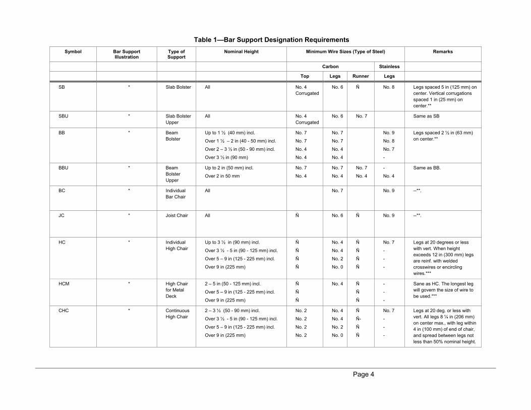
1. Bar Supports. Fabricate all wire bar supports as per the illustrations given in Table 1.
a. Stainless Wire
For nominal heights exceeding 3.5 in (90 mm), attach stainless steel extensions to the bottom of each leg.
Design the leg extensions so that no portion of the carbon steel wire will be unprotected closer than 3/4 in (20
mm) from the form surface.
b. Plastic Protected
Apply plastic protection by dipping the bar support in plastic or by molding legs to the top wire.
1) Apply a plastic coat at least 3/32 in (2.4 mm) thick at points of contact with the form.
2) Extend the plastic upward on the wire to a point at least 1/2 in (13 mm) above the form.
3) Turn up all legs on wire bar supports at least 1/8 in (3 mm).
c. Epoxy Powder Coated Wire

Section 511—Reinforcement Steel
Page 3
Apply an epoxy powder coat at least 0.006 in (0.15 mm) thick.
Page 4
Table 1—Bar Support Designation Requirements
Symbol Bar Support Illustration
Type of Support
Nominal Height Minimum Wire Sizes (Type of Steel) Remarks
Carbon Stainless
Top Legs Runner Legs
SB * Slab Bolster All No. 4
Corrugated
No. 6 Ñ No. 8 Legs spaced 5 in (125 mm) on
center. Vertical corrugations
spaced 1 in (25 mm) on
center.**
SBU * Slab Bolster
Upper
All No. 4
Corrugated
No. 6 No. 7 Same as SB
BB
* Beam
Bolster
Up to 1 ½ (40 mm) incl.
Over 1 ½ – 2 in (40 - 50 mm) incl.
Over 2 – 3 ½ in (50 - 90 mm) incl.
Over 3 ½ in (90 mm)
No. 7
No. 7
No. 4
No. 4
No. 7
No. 7
No. 4
No. 4
No. 9
No. 8
No. 7
-
Legs spaced 2 ½ in (63 mm)
on center.**
BBU
* Beam
Bolster
Upper
Up to 2 in (50 mm) incl.
Over 2 in 50 mm
No. 7
No. 4
No. 7
No. 4
No. 7
No. 4
-
No. 4
Same as BB.
BC * Individual
Bar Chair
All No. 7 No. 9 --**.
JC * Joist Chair
All Ñ No. 6 Ñ No. 9 --**.
HC * Individual
High Chair
Up to 3 ½ in (90 mm) incl.
Over 3 ½ - 5 in (90 - 125 mm) incl.
Over 5 – 9 in (125 - 225 mm) incl.
Over 9 in (225 mm)
Ñ
Ñ
Ñ
Ñ
No. 4
No. 4
No. 2
No. 0
Ñ
Ñ
Ñ
Ñ
No. 7
-
-
-
Legs at 20 degrees or less
with vert. When height
exceeds 12 in (300 mm) legs
are reinf. with welded
crosswires or encircling
wires.***
HCM * High Chair
for Metal
Deck
2 – 5 in (50 - 125 mm) incl.
Over 5 – 9 in (125 - 225 mm) incl.
Over 9 in (225 mm)
Ñ
Ñ
Ñ
No. 4 Ñ
Ñ
Ñ
-
-
-
Sane as HC. The longest leg
will govern the size of wire to
be used.***
CHC * Continuous
High Chair
2 – 3 ½ (50 - 90 mm) incl.
Over 3 ½ - 5 in (90 - 125 mm) incl.
Over 5 – 9 in (125 - 225 mm) incl.
Over 9 in (225 mm)
No. 2
No. 2
No. 2
No. 2
No. 4
No. 4
No. 2
No. 0
Ñ
Ñ-
Ñ
Ñ
No. 7
-
-
-
Legs at 20 deg. or less with
vert. All legs 8 ¼ in (206 mm)
on center max., with leg within
4 in (100 mm) of end of chair,
and spread between legs not
less than 50% nominal height.
Section 511—Reinforcement Steel
Page 5
CHCU
* Continuous
High Chair
Upper
2 – 5 in (50 - 125 mm) incl.
Over 5 – 9 in (125 - 225 mm) incl.
Over 9 in (225 mm)
No. 2
No. 2
No. 2
No. 4
No. 2
No. 0
No. 4
No. 4
No. 4
-
-
-
CHCM
*
Continuous
High Chair
for Metal
Deck
Up to 2 in (50 mm) incl.
Up to 2 in (50 mm) incl.
Over 2 – 5 in (50 - 125 mm) incl.
No. 4
No. 2
No. 2
No. 6
No. 4
No. 4
No. 4
No. 4
No. 4
No. 4 top wire: maximum leg
spacing
5 in (125 mm) on center. No. 2
top wire: maximum is 10 in
(250 mm) on center.****
UJC * Upper Joist
Chair
-1 to + 3 ½ in ( -25 to +90 mm) incl.
(measured from form to top of middle
portion of saddle bar) in ¼ in (6 mm)
increments
No. 13 Bar
or
1/2 in (13
mm)
No. 2 Ñ - Legs spaced 14 in (350 mm)
on center.
CS * Continuous
Support
1 ½ - 5 in (40 - 125 mm) incl.
Over 5 – 7 ½ in (125 - 190 mm) incl.
Over 7 ½ - 12 in (190 - 300 mm) incl.
No. 8
No. 6
No. 4
No. 8
No. 6
No. 4
No. 8
No. 6
No. 4
- Legs spaced 6 in (150 mm) on
center, 4 in (100 mm) on
center at bend point. Middle
runner used with heights over
7 in (175 mm).
―Zig Zag‖ width: 8 in (200 mm)
min.
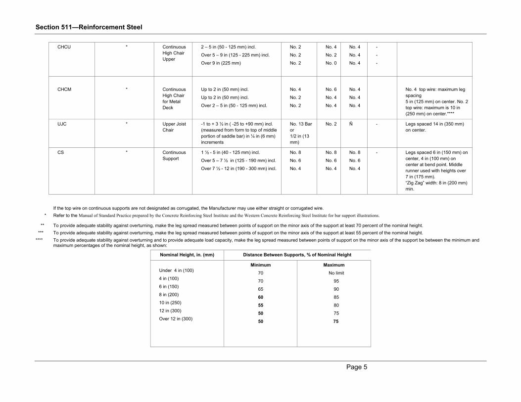
If the top wire on continuous supports are not designated as corrugated, the Manufacturer may use either straight or corrugated wire.
* Refer to the Manual of Standard Practice prepared by the Concrete Reinforcing Steel Institute and the Western Concrete Reinforcing Steel Institute for bar support illustrations.
** To provide adequate stability against overturning, make the leg spread measured between points of support on the minor axis of the support at least 70 percent of the nominal height.
*** To provide adequate stability against overturning, make the leg spread measured between points of support on the minor axis of the support at least 55 percent of the nominal height.
**** To provide adequate stability against overturning and to provide adequate load capacity, make the leg spread measured between points of support on the minor axis of the support be between the minimum and maximum percentages of the nominal height, as shown:
Nominal Height, in. (mm) Distance Between Supports, % of Nominal Height
Under 4 in (100)
4 in (100)
6 in (150)
8 in (200)
10 in (250)
12 in (300)
Over 12 in (300)
Minimum
70
70
65
60
55
50
50
Maximum
No limit
95
90
85
80
75
75
Section 511—Reinforcement Steel
Page 6
Page 7
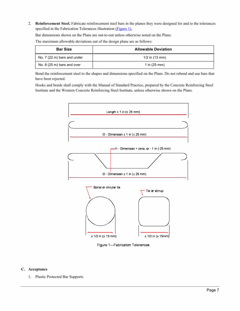
2. Reinforcement Steel. Fabricate reinforcement steel bars in the planes they were designed for and to the tolerances
specified in the Fabrication Tolerances illustration (Figure 1).
Bar dimensions shown on the Plans are out-to-out unless otherwise noted on the Plans.
The maximum allowable deviations out of the design plane are as follows:
Bar Size Allowable Deviation
No. 7 (22 m) bars and under 1/2 in (13 mm)
No. 8 (25 m) bars and over 1 in (25 mm)
Bend the reinforcement steel to the shapes and dimensions specified on the Plans. Do not rebend and use bars that
have been rejected.
Hooks and bends shall comply with the Manual of Standard Practice, prepared by the Concrete Reinforcing Steel
Institute and the Western Concrete Reinforcing Steel Institute, unless otherwise shown on the Plans.
C. Acceptance
1. Plastic Protected Bar Supports
Section 511—Reinforcement Steel
Page 8
If using Plastisol, test the tensile strength of 1,500 to 2,000 psi (10 to 13.5 MPa) and the Shore A hardness of 80 to
100 durometers.
a. Test the insolubility of the Plastisol by immersing it in methyl-ethyl-ketone (MEK commercial grade 100
percent solution) for one hour.
b. Use the ―Performance Test Procedure for Plastic Protected Bar Supports‖ in the CRSI Manual of Standard
Practices. Ensure that the plastic does not deform permanently when heated to 170 °F (77 °C).
c. Reject any material that shows metal exposed at points of contact after being heated.
d. Reject any material that shatters or severely cracks under an impact loading subjected at 5 °F (–15 °C). Reject
any plastic on the fabricated unit that chips, cracks, or peels under ordinary job conditions.
D. Materials Warranty
General Provisions 101 through 150.
511.2.01 Delivery, Storage, and Handling
After reinforcement steel is fabricated by one of the steel fabricators listed on QPL 12, handle and store it as follows:
Load, transport, unload, and handle reinforcement steel in a way that prevents damage.
Block unloaded reinforcement steel off the ground and store it in piles separated by size and type.
Protect reinforcement steel from the weather if prolonged exposure is expected and the Engineer requires the
protection.
511.3 Construction Requirements
511.3.01 Personnel
General Provisions 101 through 150.
511.3.02 Equipment
General Provisions 101 through 150.
511.3.03 Preparation
Before placing reinforcement, clean off loose mill scale, rust scale, and coatings that will destroy or materially reduce the
bond.
511.3.04 Fabrication
See Subsection 511.2.B, ―Fabrication‖ and Subsection 853.2.01.B, ―Fabrication.‖
511.3.05 Construction
Bar schedules are shown on the Plans as a service. The Contractor is responsible for conforming to the Plan details. If there is
a discrepancy between Plan details and bar schedules, the Plan details take precedence.
Space reinforcement steel within permissible tolerances. Tie and support the reinforcement steel so it cannot move during
concrete placement.
Twist bar ties at least two full turns. The Engineer may require double bar ties if single bar ties do not keep the bar
reinforcing steel secure under construction traffic.
Tie epoxy-coated reinforcement steel with the epoxy-coated or plastic-coated tie wire specified in Section 853.
Use the following placing requirements:
A. Footing Reinforcement Steel
1. Footing Ties. Tie mat steel at each intersection on the outer edges and at alternate intersections within the mat.
Section 511—Reinforcement Steel
Page 9
2. Footing Steel Support. Support mat steel using precast blocks with the maximum dimensions of 4 in x 4 in (100
mm x 100 mm) Plan clearance. Fasten the precast blocks with cast-in wires.
Steel may be supported by other satisfactory means approved by the Engineer. Do not use rocks or random pieces of
broken concrete to support steel.
3. Footing Steel Tolerances. Place mat steel within 1/2 in (15 mm) vertically from the bottom clearance and 1 in
(25 mm) from the side clearance. Do not deviate more than 1 in (25 mm) from the location indicated on the Plans as
seen in the Plan view.
B. Column and Wall Dowel Bars
1. Dowel Bar Position. Position dowel bars so the column bars or vertical wall bars can be spliced and tied in the
location the Plan specifies.
2. Dowel Bar Support. Before pouring concrete in any footing, do the following:
a. Place dowel bars.
b. Construct a rigid template across the top of the footing to support the dowel bars.
c. Attach dowel bars to the template so they cannot move during concrete placement.
d. Do not push dowel bars into wet concrete after placing the concrete.
3. Dowel Bar Tolerances. Place dowel bars within 1/2 in (15 mm) of Plan location. Do not deviate more than 1/4 in
(6 mm) on the side clearance.
C. Column Reinforcement Steel
1. Column Steel Support. Space steel off side forms using precast blocks with maximum dimensions of 2 in x 2 in x
Plan clearance (50 mm x 50 mm). Fasten the blocks with cast-in wires.
2. Vertical Bar Tolerances. Place vertical bars within 1/2 in (15 mm) of the location indicated on the Plan. Do not
deviate more than 1/4 in (5 mm) on the side form clearance.
3. Hoop Tolerances. Place hoops within 1 in (25 mm) of specified locations. Do not deviate more than 1/4 in (6 mm)
on the side form clearance.
4. Hoop Ties. Tie hoops as follows:
a. Tie hoops at intersections with dowel bars and corner vertical bars.
b. Tie other vertical bars to at least every third hoop on a staggered basis, both vertically and horizontally.
D. Wall Reinforcement Steel
1. Wall Steel Support. Space steel and mat supports as follows:
a. Space steel off side forms using precast blocks with maximum dimensions of 2 in x 2 in x Plan clearance (50
mm x 50 mm). Fasten the blocks with cast-in wires.
b. Space mat steel using satisfactory spacing devices approved by the Engineer between wall mats. Ensure that the
spacing devices provide enough space between steel mats according to the Plans.
2. Wall Bar Tolerances. Space wall bars within 1 in (25 mm) for any bar. Do not allow the tolerance to accumulate
causing an omission of bars. Do not deviate more than 1/4 in (6 mm) on the side form clearance.
Shift bars more than the tolerance only when necessary to clear a fixture. Do not reduce the number of bars specified
for the pour. Place any remaining bars on either side of the fixture to the spacing specified on the Plans and to the
tolerance specified in the previous paragraph.
3. Wall Ties. Tie wall steel as follows:
a. Tie steel at each intersection on the outer edges and at every third intersection within the mat.
b. For large walls, tie steel at alternate intersections or at each intersection, if necessary.
c. Check for bar displacement after the initial tying and correct it before pouring concrete.
Section 511—Reinforcement Steel
Page 10
E. Beam and Cap Reinforcement Steel
1. Beam and Cap Steel Support. Support beam and cap steel as follows:
a. Space upper main longitudinal steel (located below the top bars) vertically using precast blocks with maximum
dimensions of 2 in x 2 in x Plan clearance (50 mm x 50 mm). Fasten the blocks with cast-in wires.
b. Maintain side form clearance using precast blocks with maximum dimensions of 2 in x 2 in x Plan clearance (50
mm x 50 mm). Fasten the blocks with cast-in wires.
c. Maintain bottom clearances using approved beam bolsters (see symbol ―BB‖ on the Table of Bar Support
Designation Requirements (Table 1).
d. Support additional layers of main longitudinal bottom steel in beams and caps that are not bundled from the
lower layers with upper beam bolsters placed directly over lower supports. Refer to symbol ―SBU‖ on the Table
of Bar Support Designation Requirements (Table 1).
e. Space beam bolsters no more than 2 ft (600 mm) from the end of a beam or cap. Additional bolsters will be
required at a maximum spacing of 4 ft (1.2 m).
2. Beam and Cap Steel Tolerances. Place the bottom and top clearance of a layer of main longitudinal steel within
1/4 in (6 mm) of the Plan vertical dimension for that layer. Do not deviate more than 1/2 in (15 mm) on side form
clearance.
Place each stirrup within 1 in (25 mm) of its specified location.
If transverse spacing is not specified on the Plans, ensure that the main steel in beams and in tops and bottom of caps
has at least 2 in (50 mm) horizontal clearance between bars.
3. Beam and Cap Steel Ties. Tie beam and cap steel as follows:
a. Tie intersecting bars.
b. Ensure that ties on bundled bars are spaced no more than 6ft (1.8 m) apart.
c. Ensure that bundled bars have at least three ties per bundle.
F. Box Culvert Slabs
1. Box Culvert Slab Support. Support box culvert slabs as follows:
a. Support walls. Place steel supports according to the requirements for walls in Subsection 511.3.05.D, ―Wall
Reinforcement Steel.‖
b. Support bottom slabs. Place supports for single mat steel or for bottom mat steel according to the requirements
for footings in Subsection 511.3.05.A, ―Footing Reinforcement Steel.‖
If more than one mat of steel is required by the Plans, support the top mat from the bottom mat using upper
beam bolsters (SBU) or other satisfactory means approved by the Engineer.
c. Support top slabs. Support the top mat steel of top slabs using either of the following:
Continuous high chairs placed near each end of the top bends of truss bars. Refer to symbol ―CHC‖ on
the Table of Bar Support Designation Requirements (Table 1).
Individual high chairs at a maximum longitudinal spacing of 4 ft (1.2 m). Refer to symbol ―HC‖ on the
Table of Bar Support Designation Requirements (Table 1).
Support the bottom mat steel of top slabs as follows:
1) Use slab bolsters spaced approximately 12 in (300 mm) from the inside faces of walls. Refer to symbol
―SB‖ on the Table of Bar Support Designation Requirements (Table 1)
2) Additional bolsters will be required along the length of the slab at a maximum spacing of approximately
4 ft (1.2 m) to maintain the bottom clearance.
3) The Contractor may support bottom mats using precast blocks spaced approximately 4 ft (1.2 m)
(maximum) in any direction.
Section 511—Reinforcement Steel
Page 11
Blocks shall have maximum dimensions of 2 in x 2 in x Plan clearance (50 mm x 50 mm). Fasten the
blocks with cast-in wires.
If the Engineer determines that precast blocks do not provide proper support and maintain bottom
clearances, use slab bolsters. Refer to symbol ―SB‖ on the Table of Bar Support Designation Requirements
(Table 1).
2. Box Culvert Slab Tolerances. Place bar reinforcing steel in the walls according to the tolerance requirements in
Subsection 511.3.05.D.2, ―Wall Bar Tolerances.‖
Place top and bottom slab reinforcing bar mats according to the tolerances specified in Subsection 511.3.05.G.6,
―Bridge Deck Slab Tolerances.‖
3. Box Culvert Slab Ties. For top and bottom slabs, tie the reinforcing steel in each layer at the following locations:
Each intersection on the outer edges
Every third intersection within the mat
G. Bridge Deck Slabs
1. Bridge Deck Slab Bottom Mat Support—Slab Bolsters. Support bridge deck slab bottom mat reinforcing with
slab bolsters as follows:
a. Use lines of longitudinal slab bolsters. Refer to symbol ―SB‖ on the Table of Bar Support Designation
Requirements (Table 1).
b. Ensure that slab bolsters that contact the forms are corrosion resistant.
c. Place slab bolsters along both sides of each beam approximately 6 in (150 mm) to 12 in (300 mm) from the
beam edges.
d. If the spacing between the lines of bolsters exceeds 4 ft (1.2 m), place an additional row or rows of bolsters
parallel to and in between the lines of bolsters so the maximum spacing between the lines of bolsters does not
exceed 4 ft (1.2 m).
e. If the reinforcement extends 12 in (300 mm) or more past bolsters on curb or median overhangs, place an
additional row of bolsters approximately 4 in (100 mm) from the end of the reinforcement.
f. On skewed bridges where main (transverse) deck steel is not placed parallel to skew, support discontinuous
ends of cutoff transverse bars using slab bolsters. Refer to symbol ―SB‖ on the Table of Bar Support
Designation Requirements (Table 1). Place bolsters parallel to skew and as close to the cut ends of bars as
possible.
2. Bridge Deck Slab Bottom Mat Support—Precast Blocks. The Contractor may support bottom mat reinforcing in
the panels between beams using precast blocks instead of slab bolsters as follows:
a. Use precast blocks with maximum dimensions of 2 in x 2 in x Plan clearance (50 mm x 50 mm).
b. Fasten the blocks with cast-in wires.
c. Space the blocks a maximum of 3 ft (1 m) longitudinally.
d. Space the blocks transversely according to the requirements for slab bolsters described in
Subsection 511.3.05.G.1, ―Bridge Deck Slab Bottom Mat Support—Slab Bolsters,‖ steps c, d, and e.
e. If precast blocks do not adequately support the reinforcing steel, use slab bolsters. Refer to symbol ―SB‖ on the
Table of Bar Support Designation Requirements (Table 1).
3. Bridge Deck Slab Top Mat Support Using Continuous High Chairs
Support top mat reinforcing steel with continuous high chairs as follows, except as noted in Alternate 1 and
Alternate 2. Refer to symbol ―CHC‖ on the Table of Bar Support Designation Requirements (Table 1).
a. Use a line of longitudinal continuous high chairs. Refer to symbol ―CHC‖ on the Table of Bar Support
Designation Requirements (Table 1).
Section 511—Reinforcement Steel
Page 12
b. Place the continuous high chairs 6 in (150 mm) from the edge along both sides of each beam.
c. Place another line of continuous high chairs 6 in (150 mm) from each outside edge of the slab.
d. If the spacing between the lines of continuous high chairs exceeds 4 ft (1.2 m), place an additional row or rows
of continuous high chairs so the maximum spacing between the lines of continuous high chairs does not exceed
4 ft (1.2 m). Refer to symbol ―CHC‖ on the Table of Bar Support Designation Requirements (Table 1).
4. Bridge Deck Slab Top Mat Support Using Alternate 1. When truss bars are used for main slab transverse
reinforcing, support top mat steel using individual high chairs as follows:
a. Place individual high chairs in a line 6 in (150 mm) from the edges along both sides of each beam. Refer to
symbol ―HC‖ on the Table of Bar Support Designation Requirements (Table 1).
b. Place another line 6 in (150 mm) from each outside edge of the slab.
Maximum spacing for individual high chairs is 3 ft (1 m) longitudinally and 4 ft (1.2 m) transversely.
5. Bridge Deck Slab Top Mat Support Using Alternate 2. When truss bars are not used for main slab transverse
einforcing, support top mat steel using continuous high chairs upper as follows:
a. Place lines of longitudinal continuous high chairs upper, directly over the lines of longitudinal slab bolsters that
support the bottom mat steel. Refer to symbols ―CHCU‖ and ―SB‖ on the Table of Bar Support Designation
Requirements (Table 1).
b. On skewed bridges where main (transverse) deck steel is not placed parallel to skew, support discontinuous
ends of cutoff transverse bars using continuous high chairs (CHC) placed parallel to skew as close to the cut
ends of bars as possible.
c. On bridges skewed less than 75 degrees, place an additional No. 5 (16M) bar parallel to the skew for the full
deck width and as close as possible to the deck joint. Securely tie this bar to the following to maintain correct
bar mat location:
The underside of the top mat of reinforcing steel
The forms
The supports (beams)
Both forms and supports (beams)
d. When using prestressed concrete deck panels, securely tie the top mat of bar reinforcing steel to each shear bar
and pick-up loop in the panels. This keeps the top bar reinforcing mat in the correct vertical position.
6. Bridge Deck Slab Tolerances. Bridge deck slab tolerances are as follows:
a. Top and Bottom Mat. Top and bottom clearances for reinforcement steel mats shall be within 1/4 in (6 mm) of
the dimension shown on the Plans.
Do not deviate horizontal spacing or end and edge clearances of the mats more than 1/ 2 in (15 mm) from the
spacing shown on the Plans.
b. Curb and Sidewalk Bar. Place curb and sidewalk bars within 1/2 in (15 mm) in all directions of the Plan
dimension.
c. Truss Bar. If using truss bars in the bridge deck, raise the bar to meet the top clearance specified on the Plans.
Do not deviate from the bottom clearance specified on the Plans.
7. Bridge Deck Slab Bottom Mat Ties. Tie reinforcing steel as follows:
a. Tie the steel at each intersection of the outer edges and every third intersection within the mat unless the steel is
coated with epoxy.
b. Tie epoxy-coated reinforcing steel at every other intersection within the mat.
8. Bridge Deck Slab Top Mat Ties. Tie reinforcing steel as follows:
Section 511—Reinforcement Steel
Page 13
a. Tie the steel at each intersection on the outer edges and every other intersection within the mat unless the steel
is coated with epoxy.
b. Tie epoxy-coated reinforcing steel at every intersection.
H. Reinforcement Steel Splices
Furnish reinforcement steel in the full lengths shown on Plans. Splice as shown on the Plans. Do not make other splices
unless approved by the Engineer.
Place bars in continuous contact on lapped splices. Wire the bars together to maintain a clearance not less than the
minimum clear distance to other bars and to the surface of the concrete.
Splice length shall be at least 12 in (300 mm) on No. 4 (13M) longitudinal bars for cast-in-place box culverts, unless
indicated otherwise on the Plans.
I. Reinforcement Steel Welds
Weld reinforcement steel only where shown on Plans.
J. Minimum Steel Spacing Requirements
The minimum spacing limitations are as follows unless shown otherwise on the Plans
Clear Distance Between Parallel Bars
(Shall be at least the largest measurement listed)
Cast-in-Place Concrete Precast Concrete Manufactured Under Plant Control
Conditions
1.5 bar diameters 1 bar diameter
1.5 times the maximum size of the coarse aggregate 1-1/3 times the maximum size of the coarse aggregate
1-1/2 in (40 mm) 1 in (25 mm)
511.3.06 Quality Acceptance
Place reinforcement steel and have it inspected and approved by the Engineer before placing concrete.
If this requirement is violated, the Engineer may reject the concrete and require the Contractor to remove it.
511.3.07 Contractor Warranty and Maintenance
General Provisions 101 through 150.
511.4 Measurement
This work is measured for payment as an accepted lump quantity or in pounds (kilograms) of accepted bar reinforcement
steel, whichever is shown on the Plans. The Department reserves the right to revise bar reinforcement steel quantities to
correct errors and reflect changes on the Plans.
Payment Per Lump Sum
The quantity of bar reinforcing steel measured for payment per Lump Sum basis shall conform to the Plan details
and will include reinforcement in concrete handrailings, concrete parapets, and barriers.
Payment Per Pound (Kilogram)
The quantity of bar reinforcement steel measured for payment per pound (kilogram) in bridges and concrete box
culverts will be the algebraic sum of the base pay quantity and authorized quantity changes.

Section 511—Reinforcement Steel
Page 14
Reinforcement bar weight calculations will be made using the theoretical unit weight in pounds (kilograms) per foot
(meter) for deformed bars as shown in the table of Deformed Bar Designation Numbers, Units Weights, and
Nominal Dimensions (Table 2). This table is taken from ASTM A 615.
Lengths of bent bars will be the sum of the component sections of the bars as shown on the Plans.
Table 2—Deformed Bar Designation Numbers, Unit Weights, and Nominal Dimensions
Nominal Dimensions
Bar Designation No.* Unit Weight lb/ ft
(kg/m)
Diameter in
(mm)
Cross-sectional
Area, in² (mm²)
Perimeter in (mm)
3 (10M) 0.376 (0.560) 0.375 (9.5) 0.11 (71) 1.178 (29.9)
4 (13M) 0.668 (0.994) 0.500 (12.7) 0.20 (129) 1.571 (39.9)
5 (16M) 1.043 (1.552) 0.625 (15.9) 0.31 (199) 1.963 (49.9)
6 (19M) 1.502 (2.235) 0.750 (19.1) 0.44 (284) 2.356 (59.8)
7 (22M) 2.044 (3.042) 0.875 (22.2) 0.60 (387) 2.749 (69.8)
8 (25M) 2.670 (3.973) 1.000 (25.4) 0.79 (510) 3.142 (79.8)
9 (29M) 3.400 (5.060) 1.128 (28.7) 1.00 (645) 3.544 (90.0)
10 (32M) 4.303 (6.404) 1.270 (32.3) 1.27 (819) 3.990 (101.4)
11 (36M) 5.313 (7.907) 1.410 (35.8) 1.56 (1006) 4.43 (112.5)
14 (43M) 7.650 (11.38) 1.693 (43.0) 2.25 (1452) 5.32 (135.1)
18 (57M) 13.600 (20.24) 2.257 (57.3) 4.00 (2581) 7.09 (180.1)
*Bar numbers are based on the number of eighths-of-an-inch included in the nominal diameter of the bars. Metric
equivalents are rounded to the nearest whole millimeter.
511.4.01 Limits
A. Construction of Minor Items
No separate measurement or payment will be made for the cost of bar reinforcement steel used in constructing minor
items.
B. Prestressed Concrete Bridge Members
Bar reinforcement steel in prestressed concrete bridge members will be considered a component part of the members.
The cost shall be included in the Contract Price for prestressed concrete bridge members.
C. Handrail End Posts
Reinforcement steel in handrail end posts that are a part of the superstructure or substructure will be considered part of
the superstructure or substructure quantities.
D. Lap Splices
Extra reinforcement steel in lap splices permitted for convenience at splices not shown on the Plans will not be measured
for payment.
Section 511—Reinforcement Steel
Page 15
511.5 Payment
This work will be paid for at the Contract Price per Lump Sum or per pound (kilogram) of bar reinforcement steel, each
complete in place.
Payment will be made under:
Item No. 511 Superstructure Reinforcement Steel—Bridge No._____ Per lump sum
Item No. 511 Bar Reinforcement Steel Per pound (kilogram)
511.5.01 Adjustments
A. Plan Quantities
Assume the burden of proof for errors of commission or omission in the Plan quantities.
The Department will not consider requests for additional monies because of Plan errors unless they are submitted with
the bar lists and weights described in Subsection 511.1.03.B, ―Bar Lists and Calculated Weights.‖ Projects involving
multiple bridges or non-skewed concrete box culverts will be considered on an individual basis.
Quantities for bridges and concrete box culverts shown on the Contract Plans (including Standard Plans) will be
considered the Base Pay Quantity. Calculated additions or deductions will be applied to the Base Pay Quantity when
quantity changes authorized by the Engineer are made. Changes include, but are not limited to, the following:
Raising or lowering foundations
Lengthening or shortening concrete box culverts
Correcting Plan quantity errors or placement details
B. Lump Sum Payment
When authorized quantity changes in the bar reinforcement Plan Quantity are made, Lump Sum payments will be
adjusted on a pro-rata basis as follows:
1. If the calculated bar reinforcement weights furnished by the Contractor differ from the Plan Quantity by more than
two percent, the Bridge Office will recalculate the plan quantity.
If the recalculated Plan Quantity differs by more than two percent from the original Plan Quantity, the Plan quantity will
be revised by the Bridge Office to equal the recalculated quantity or the Contractor’s quantity, whichever is lower. The
Lump Sum payment will be adjusted on a pro-rata basis.
When the Contractor exercises an optional feature of the Plans that results in the only increase or decrease to the Base
Pay Quantity, there will be no increase or decrease in payment. However, if the two percent variation is being
considered, the effects of the optional feature will favor the Department.
C. Prestressed Concrete Deck Panels
Payment for prestressed concrete deck panels will be 35 percent of the lump sum superstructure reinforcement steel
price. Payment will be made after panels are placed.
Payment for post-tensioned box girder bridges will be 35 percent of the lump sum superstructure reinforcement steel
price only for the reinforcement steel in the top slab of the box.