Embed Size (px)
Citation preview
SECTION 5.28.30 - ELECTRONIC DETECTION AND ALARM DESIGN AND CONSTRUCTION STANDARD
PART 1 GENERAL
1.01 Scope of Standard
A. This Standard is intended to assure that fire detection/alarm systems at The University of Texas at Austin provide the highest level of fire safety possible. . This document is not intended to be a guide specification.
1.02 Scope of Work
A. TThis standard is to be used in the development of all fire detection/alarm system designs for buildings and structures at The University of Texas at Austin.
B. This standard is to apply to all fire detection/alarm system components and equipment installed at any University of Texas at Austin campus during new construction or as part of any improvement project.
C. The work addressed in this section consists of a fire protection system, which may include, and at least will be coordinated with all of the following building systems or components:
1. Fire Suppression Systems.
2. HVAC and smoke control systems; fire, smoke, and combination fire/smoke dampers.
3. Emergency power systems.
4. Elevator installation. See the Texas State Elevator Code ASME/ANSI A17.1 and ASME/ANSI A17.3.
5. Central control and monitoring system.
6. Security Systems
D. Referenced Publications
The documents or portions thereof listed in this section shall be considered part of the requirements of this document. (Utilize latest editions)
1. NFPA 1, Uniform Fire Code
2. NFPA 13, Standard for the Installation of Sprinkler Systems
3. NFPA 14, Standard for the Installation of Standpipe and Hose Systems
4. NFPA 70, National Electrical Code
Design & Construction Standards, Revised September 2008 5.28.30-1
SECTION 5.28.30 - ELECTRONIC DETECTION AND ALARM DESIGN AND CONSTRUCTION STANDARD
5. NFPA 72, National Fire Alarm Code
6. NFPA 90A, Standard for the Installation of Air-Conditioning and Ventilating Systems
7. NFPA 101, Life Safety Code
8. NFPA 5000, Building Construction and Safety Code
9. IBC-International Building Code
10. IFC-International Fire Code
11. UL Standard 268, Smoke Detectors for Fire Protective Signaling Systems
12. UL Standard 268A, Smoke Detectors for Duct Application
13. UL Standard 346, Waterflow Indicators for Fire Protective Signaling Systems
14. UL Standard 521, Heat Detectors for Fire Protective Signaling Systems
15. UL Standard 864, Control Units for Fire Protective Signaling Systems
16. UL Standard 1424, Cables for Power—Limited Fire Protective Signaling Systems
17. UL Standard 1480, Speakers for Fire Protective Signaling Systems,
18. UL Standard 1481, Power Supplies for Fire Protective Signaling Systems
19. UL Standard 1711, Amplifiers for Fire Protective Signaling Systems
20. UL Standard 1971, Signaling Devices for the Hearing Impaired
21. ADA-Americans with Disabilities Act
22. TAS-Texas Accessibility Standards
23. American Society of Mechanical Engineers (ASME)/American National Standards Institute (ANSI):
a. ANSI A17.1, Elevator Code, latest edition. b. ANSI A17.3, Elevator Code for Existing Elevators, latest edition. c. ANSI A117.1, Accessibility Code, latest edition.
1.03 Objectives
Design & Construction Standards, Revised September 2008 5.28.30-2
SECTION 5.28.30 - ELECTRONIC DETECTION AND ALARM DESIGN AND CONSTRUCTION STANDARD
A. This standard is intended to achieve consistently high levels of fire detection/alarm system performance by:
1. Allowing designers to incorporate required or desired features as early in the design development process as possible.
2. Assuring all systems are designed to meet all applicable codes, ordinances, laws, and sound engineering judgment.
3. Providing a basis for a general understanding among all parties involved in the design of systems.
1.04 Concepts
A. All systems are to be compliant with applicable paragraphs of National Fire Protection Association (NFPA) Code 101 "Life Safety Code".
B. All systems are to be compliant with the requirements of NFPA 72 "National Fire Alarm Code".
1.05 System Features
A. All system product lines must be comprised of components capable of providing the following features when appropriate and specified by the project documents or the University:
1. Floor above/floor below notification.
2. Private alarm notification.
3. Positive alarm sequence.
4. Voice alarm notification.
5. Fireman's communications.
6. Elevator capture/recall.
7. Elevator power shunt trip.
8. Smoke control/fan shutdown.
9. Door release.
10. Release locks on normally locked egress doors.
11. Release and monitoring of clean agent and/or preaction sprinkler systems.
Design & Construction Standards, Revised September 2008 5.28.30-3
SECTION 5.28.30 - ELECTRONIC DETECTION AND ALARM DESIGN AND CONSTRUCTION STANDARD
12. Monitor non-water based fire suppression systems.
13. Multiple channel voice
B. Provide audible alarming throughout the building in accordance with NFPA 72.
C. Visual alarming to ADA levels and TAS requirements must be provided throughout the building.
D. Smoke detectors must be provided at all elevator lobbies, elevator equipment rooms and elevator hoistways to perform capture/recall functions.
E. All systems must be designed to provide manual means of alarm initiation at every exit from every level. Elevators are not to be considered an exit or route of egress.
1.06 Description of Work
A. All designs must provide for each building a complete and working digital, addressable, closed circuit, automatic and manual fire detection / alarm system for each floor of the building to perform detection, monitoring, and alarm functions for the building.
1.07 Quality Assurance
A. Installer Qualifications:
1. Authorized and designated representative of fire alarm manufacturer to sell, install, and service proposed manufacturer's equipment. Verify equipment supplier has technical factory training specifically for the system proposed.
2. Licensed by State Fire Marshall to sell, install, and service fire alarm systems.
3. Actively engaged in business of selling, installing, and servicing fire alarm systems for at least five years with minimum of ten such installations completed and operating properly.
4. Equipment furnished shall be of current manufacture.
B. The equipment furnished shall be listed and approved by a testing laboratory that has been approved by the State of Texas Commission on Fire Safety. This listing shall be for all functions required by this specification.
Design & Construction Standards, Revised September 2008 5.28.30-4
SECTION 5.28.30 - ELECTRONIC DETECTION AND ALARM DESIGN AND CONSTRUCTION STANDARD
C. The Contractor shall provide a signed "Fire Alarm Certification and Description" for each system, consisting of completed copies of the appropriate pages from NFPA 72, at the final Acceptance Test.
D. Provide staff installation superintendents who are licensed by the State Fire Marshall's office for such purpose and under whose supervision installation, final connections, and testing will be performed.
E. All systems must comply with applicable paragraphs of the National Electric Code.
1.08 Submittals
Prior to installation, the following documents shall be provided to the University of Texas at Austin for reference and/or approval:
A. Shop Drawings: Include manufacturer's name, model numbers, ratings, power requirements, equipment layout, conduit, device arrangement, and complete point to point wiring diagrams along with other required information including but not limited to:
1. General Drawing Notes
2. Electrical back box requirements
3. Control Equipment Schedules
4. Panel Schematics showing all connections, between modules within panels, to all modules from field wiring with zones identified.
5. Riser Diagrams indicating circuits, type of devices, number of devices, number of conductors, conduit size, junction boxes, and zones.
6. Scaled floor plans with layout of all devices with point numbers for initiating and notification devices, wiring connections, zoning, wire sizes and routing.
a. Wattage setting for each speaker labeled adjacent to the speaker b. Candela rating for each strobe labeled adjacent to the strobe
7. Detailed Legend
8. Fire safety and related symbols shown on drawings and diagrams shall comply with NFPA 170.
9. Detailed input/output matrix.
Design & Construction Standards, Revised September 2008 5.28.30-5
SECTION 5.28.30 - ELECTRONIC DETECTION AND ALARM DESIGN AND CONSTRUCTION STANDARD
B. Product Data: Provide electrical characteristics, connection requirements and compatibility listing showing that components are compatible with each other including but not limited to:
1. Full equipment list including model numbers and quantities
2. Complete system operation
3. Highlighted Data Sheets on Devices and Products
a. Fire Alarm Control Panel b. Wiring c. Batteries d. Detectors e. Manual Stations f. Audible Signaling Devices g. Visual Signaling Devices h. Control Devices
4. Wiring diagrams of all equipment
5. Installation instructions for all equipment
6. Equipment testing procedures
7. Equipment maintenance manuals
8. Wire data sheets.
C. System Calculations - Complete calculations shall be provided which show the electrical load on the following system components:
1. Each system power supply, including stand alone booster supplies
2. Standby Battery Calculations plus a 20 percent derating factor
3. Voltage drop calculations for each type of circuit (identify all mathematical formulas, variables, and constants)
4. dB loss calculations for speaker circuits
5. Speaker circuit loading and amplifier loading
6. Strobe circuit loading
7. Each auxiliary control circuit that draws power from any system power supply
D. Software and Database Information:
Design & Construction Standards, Revised September 2008 5.28.30-6
SECTION 5.28.30 - ELECTRONIC DETECTION AND ALARM DESIGN AND CONSTRUCTION STANDARD
1. Proposed point numbers,
2. Labels of all addressable devices
3. English action messages.
4. Add Programming rules, Equations, with comments listed.
5. Please send a copy to FSS and PMCS’ Project Support Fire Protection Engineer.
E. The submittal package shall be signed by State of Texas Alarm Planning Superintendent (NICET III) or signed and sealed by a Professional Engineer (P.E.) registered in the State of Texas.
PART 2 PRODUCTS
2.01 Fire Alarm Control Panel (FACP)
A. Acceptable Manufacturers models GE-EST 3 Notifier, 3030 Siemens, XLSV FIRE FINDER, and Simplex 4100U.
B. All fire alarm control panels must be intelligent, addressable Central Processing Units (CPU) based and meets the latest edition of UL 864.
C. All FACPs must be capable of providing circuit integrity monitoring for all Signaling Line Circuits at a level of Class A, Style 6, as defined in NFPA 72.
D. All FACPs must be capable of providing circuit integrity monitoring of Initiating Device Circuits (IDC's) at a level of Class B as defined in NFPA 72.
E. All FACPs must be capable of providing circuit integrity monitoring of Notification Appliance Circuits (NAC's) at a level of Class B as defined in NFPA 72.
F. Panels shall have provisions for smoke detector "Alarm Verification" for Signaling Line Circuits must be provided.
G. Manufactured terminal boxes labeled “FIRE ALARM TERMINAL BOX” Space Age TC series or equal.
H. With each installed field device affix a label to indicate the devices full address on its signaling line circuit.
I. Mark each cable or wire to designated terminal with labeling tool.
Design & Construction Standards, Revised September 2008 5.28.30-7
SECTION 5.28.30 - ELECTRONIC DETECTION AND ALARM DESIGN AND CONSTRUCTION STANDARD
J. All FACPs must provide twenty percent (20%) excess power supply, input circuit, and output circuit capacity at final acceptance to allow for future expansion by the owner.
K. Zone labeling must be textual by alpha-numeric display at the FACP and remote annunciator to allow “first response” by persons not trained in fire alarm technology.
L. Textual (alpha-numeric) language must be conventional, concise, clear and accurate to facilitate rapid response.
M. All FACPs must provide a control to silence the Public Alarm to allow for maintenance and testing, and to reduce disruption.
N. All FACPs must provide a control to override the smoke control/fan shutdown feature to allow for maintenance and testing. Program panel to allow functions to be disabled by floor or by group as required by UT.
O. All FACPs must be connected to a Primary and Secondary Power source. The secondary power supply must be sized to provide 5 minutes of operation in alarm conditions after 24 hours of system operation in standby power. Where voice evacuation systems are utilized, 15 minutes of alarm shall be provided.
P. All FACPs must provide a separate digital address for each initiating device to facilitate rapid response and maintenance and testing.
Q. All FACPs must provide a separate digital address for each individual flow switch.
R. All programming must be permanent and non-volatile to reduce outage time due to failure.
S. All FACPs must provide a panel mounted printer to print a log of all status change activity.
T. All FACP's must be listed and approved as the smoke detector sensitivity test set to reduce maintenance costs.
U. All FACPs must be capable of providing drift compensation. Drift compensation is considered equal to adjustability at the detector.
V. All FACPs must be field programmable, using internal or connected components, for all changes, alterations, modifications, additions, deletions and hardware and software upgrades.
W. All messages shall be recorded in a female voice.
Design & Construction Standards, Revised September 2008 5.28.30-8
SECTION 5.28.30 - ELECTRONIC DETECTION AND ALARM DESIGN AND CONSTRUCTION STANDARD
X. All FACPs must be capable, using internal or connected components, of generating comprehensive reports for sensitivity, verification counts, address registers.
Y. Where a clean agent fire suppression system and/or preaction sprinkler system is specified for the project, the FACP must be UL listed for releasing service the preaction and/or clean agent system specified in Section 21 20 00. Initiating devices shall be connected to a UL listed releasing panel. All initiating, output and releasing circuits shall reside in one fire alarm control panel.
Z. A fault isolation device shall be provided electrically between each building level. This device shall be capable of automatically isolating wire-to-wire faults on each SLC to the building level involved. The device shall be powered by the SLC loop. The device shall provide visual indication at the device of a short circuit (isolate) condition. The device shall reset to the normal mode upon elimination of the wire-to-wire short. All fault isolation devices shall be physically located within the marshaling box for that floor.
2.02 Remote Monitor
A. All systems must be capable of interconnection to the Campus-Wide Proprietary Supervisory Signaling System utilizing one set of Form C contacts (one normally open, one normally closed) for transmission of each of the following signals separately:
1. ALARM
2. WATERFLOW
3. SUPERVISORY
4. TROUBLE
B. All systems must provide a Wiring Interface Panel (junction box) to accommodate the connection between the new fire alarm system and the existing Proprietary Protective Signaling System. The WIP must be accessible and located within a room that is nearest to the campus utilities tunnel system. Conduit and 18/10 conductor cabling must be provided between this panel and the FACP to perform the functions listed above.
2.03 Distributed Power Supplies
A. Distributed power supplies for powering Notification Appliance Circuits, beam smoke detectors, and control relays may be used.
Design & Construction Standards, Revised September 2008 5.28.30-9
SECTION 5.28.30 - ELECTRONIC DETECTION AND ALARM DESIGN AND CONSTRUCTION STANDARD
B. All distributed power supply inputs must be controlled by addressable interface devices located on the same floor levels as the power supply and controlled by the SLC serving the area to facilitate maintenance.
C. The distributed power supplies must be sized to provide 5 minutes of operation in alarm after 24 hours of system operation in standby power. Where voice evacuation systems are utilized, 15 minutes of alarm must be provided after operation in standby power.
2.04 Manual Pull Stations
A. All manual pull stations must be of the "double-action" type to reduce unintentional or vandal alarms. Pull stations required to break glass to activate are not acceptable. Provide pull stations that utilize the same key as FACP for resetting.
B. Each manual pull station must have a unique digital address on the SLC.
C. Where separate addressable monitor modules are used for monitoring conventional type manual pull stations, the modules are required to be installed within the manual pull station back box.
2.05 Heat Detectors
A. All heat detectors shall be fixed temperature, rate-of-rise, or combination fixed temperature and rate-of-rise, spot type.
B. Each addressable heat detector must have a unique address on the SLC
C. Non resetting detectors must give visual indication of "ALARM" condition to facilitate rapid response.
D. Where separate addressable monitor modules are used for monitoring conventional type heat detectors, the modules are required to be installed within the heat detector junction box.
2.06 Smoke Detectors
A. All spot type smoke detectors shall be photoelectric or combination photoelectric and ionization type.
B. Each smoke detector, whether spot-type, or projected-beam type, must have a unique digital address on the SLC.
C. All smoke detectors must be field measurable and adjustable for sensitivity.
D. All smoke detectors, except projected beam type, must be powered from the SLC.
Design & Construction Standards, Revised September 2008 5.28.30-10
SECTION 5.28.30 - ELECTRONIC DETECTION AND ALARM DESIGN AND CONSTRUCTION STANDARD
E. The FACP must function as the smoke detector sensitivity test set and must be approved and listed for that service.
F. All smoke detectors must meet or exceed the requirements of Underwriter's Laboratory Standard 268, as amended, and must be listed and approved for use with the FACP provided.
2.07 Duct-Mounted Smoke Detectors
A. It is the joint responsibility of the Fire Alarm and the Mechanical Contractors to assure that all supply and return air is sampled as required per NFPA 90A. Label duct work and direction of air flow and identify the proper locations for duct detectors. Provide only addressable system duct detectors, factory installed duct detectors within the air handling unit are not acceptable.
2.08 Projected-Beam Smoke Detectors
A. All projected-beam detectors must operate on the infrared principle.
B. All projected-beam detectors must have automatic gain control circuits to compensate for deterioration of signal strength due to environmental factors such as dirt and dust accumulation, component aging and temperature fluctuations.
C. Transmitting and receiving units of projected-beam detectors must be protected from physical damage.
D. All projected-beam smoke detectors must have circuits to prevent "false" alarms due to sudden and complete obscuration.
2.09 Air Sampling Smoke Detection
A. Provide air sampling smoke detection system if required by the project.
B. Locate air sampling ports in accordance with NFPA 72 and manufacturer’s requirements.
C. Maintain a maximum transport time of 120 seconds, or the transport time specified by the manufacturer, from the farthest sampling point, whichever is less.
D. Utilize CPVC piping that is listed for use in air sampling systems. Label piping as required per NFPA 72.
2.010 Waterflow Switches
Design & Construction Standards, Revised September 2008 5.28.30-11
SECTION 5.28.30 - ELECTRONIC DETECTION AND ALARM DESIGN AND CONSTRUCTION STANDARD
A. Fire detection/alarm systems must be interconnected to the fire sprinkler systems by waterflow switches must be set for a 60 second delay (retard) prior to the "ALARM".
B. Each waterflow switch must be monitored for a unique digital address on the SLC.
C. It is the responsibility of the Sprinkler Contractor to locate the waterflow switches to assure indication of water flow within the building and at each level of the building to reduce water damage.
2.011 Supervisory (Tamper) Switches
A. Connect tamper switches installed on all sprinkler or standpipe system valves to the fire alarm system to indicate closing or opening of the valves.
2.012 Audible Appliances
A. Fire alarm system audible notification appliances is required to be provided by speakers in all buildings. The fire alarm speakers will also be utilized by the mass notification system for audible notification. The fire alarm signal generated must be the distinctive three-pulse temporal pattern described by NFPA and ANSI codes.
B. The Evacuation Signal produced by the speakers must be alternated with a custom textual message as indicated in Section 3.08 below.
C. Provide audible systems with voice intelligibility measured in accordance with the guidelines in Annex A of IEC 60849, Sound Systems for Emergency Purposes. When tested in accordance with Annex B, Clause B1, of IEC 60849, the system shall exceed the equivalent of a common intelligible scale (CIS) score of 0.70.
2.013 Visual Appliances
A. All visual notification appliances must be xenon strobe, compliant with current requirements of ADA and TAS.
B. All visual notification devices within a room or adjacent space within the field of view must be synchronized as required per NFPA 72.
C. Strobes used in combination systems where the same strobe is used for both mass notification and fire notification shall be clear or nominal while meeting the listing requirements of UL 1971 and either have no marking or be marked with the word “ALERT” stamped or imprinted on the appliance and be visible to the public.
Design & Construction Standards, Revised September 2008 5.28.30-12
SECTION 5.28.30 - ELECTRONIC DETECTION AND ALARM DESIGN AND CONSTRUCTION STANDARD
2.014 Remote Annunciator
A. When required by the project, an LCD remote annunciator shall be located in an open accessible area at or adjacent to the main ground level entrance to the building. The FACP may then be located in a remote location or room.
B. Remote annunciator must display the same addressable and common signal information as the main FACP.
2.015 Monitoring Devices
A. Addressable monitoring devices used to monitor contact-closure initiating devices such as waterflow switches, and tamper switches must derive power from the SLC to which they are connected.
B. Each monitoring device must have a unique digital address on the SLC.
C. Monitoring devices used to interface smoke detectors to the SLC shall be limited to existing spot type smoke detectors or duct-mounted smoke detectors.
2.016 Control Devices
A. Addressable control devices must not control more than one type of appliance/device.
2.017 Documentation storage shall be provided at or adjacent to (within five feet of) the FACP. This storage shall be capable of storing and securing all documents required for system maintenance and response. Storage shall be separated from all active electrical, electronic, or electromechanical parts and components. If adequate, storage may contain unconnected spare/repair parts.
PART 3 INTERCONNECTION AND OPERATION
3.01 Signaling Line Circuits (SLC)
A. All FACP's must provide circuit integrity monitoring for all Signaling Line Circuits at a level of Class A, Style 6.
B. All the following devices/appliances must be individually addressed on the SLC:
1. Smoke detectors.
2. Heat detectors.
3. Manual stations.
Design & Construction Standards, Revised September 2008 5.28.30-13
SECTION 5.28.30 - ELECTRONIC DETECTION AND ALARM DESIGN AND CONSTRUCTION STANDARD
4. Monitor devices.
5. Control devices.
6. IDCs.
7. Audio NACs.
8. Visual NACs.
3.02 Initiating Device Circuits (IDC)
A. Initiating Device Circuits (IDCs) must be monitored at a level of Class B.
3.03 Notification Appliance Circuits (NAC)
A. All Notification Appliance Circuits (NACs) must be monitored at a level of Class B.
B. Direct current notification appliance power provided from a distributed power supply must be controlled by a digital addressable control device on the SLC.
C. Audible notification appliances and visual notification appliances must always be connected to separate NACs to facilitate maintenance.
3.04 Auxiliary Functions
A. Locate control devices utilized for operating auxiliary functions mounted within 3 feet of the system being controlled as required per NFPA 72.
3.05 Floor Above/Floor Below Notification
A. Selective evacuation shall be permitted if approved by the AHJ.
B. In high rise structures, each level must constitute a minimum of one audio Notification Appliance Circuit and one visual Notification Appliance Circuit. NACs must be capable of initiating a general alarm or allow selectable notification.
C. The FACP must also provide a control at the panel to allow sounding the Public Alarm throughout the structure (All-call) and activate both audio and visual notification for building evacuation at the FACP.
3.06 Positive Alarm Sequence
A. Positive alarm sequencing shall be permitted.
3.07 Voice Alarm Notification
Design & Construction Standards, Revised September 2008 5.28.30-14
SECTION 5.28.30 - ELECTRONIC DETECTION AND ALARM DESIGN AND CONSTRUCTION STANDARD
A. Where required by code, the audible portion of the Public Alarm for all systems must be Voice Alarm Provide speakers for annunciation of voice messages. Signals generated must be the Distinctive Evacuation Signal (three-pulse temporal pattern) alternated with a digitized custom textual message.
B. Audible message required for voice evacuation shall be as follows:
"Attention, please! Attention, please! An emergency situation has been detected in the building. Please evacuate immediately in accordance with safety and security regulations. Use stairwells; do NOT use elevators. Repeat: use stairwells; do NOT use elevators. Go to your assigned area outside the building or follow the instructions of the staff or emergency personnel. Do not re-enter the building until instructed to do so by emergency personnel. Please evacuate the building immediately."
C. The digitized audible message shall sound twice, and then the three pulse temporal pattern shall resume.
D. The FACP shall provide a microphone and associated controls to allow voice paging to selected areas.
3.08 Fire Department Communication System
A. Where required by code, provide a complete and separate two-way fire department communication system.
B. Electrically supervised two way fireman’s phone jacks must be provided at the entrance to all elevators, enclosed stairwells, elevator lobbies, emergency and standby power rooms. Phone jacks are also required in fire pump rooms and fire command centers, where provided.
C. Wiring for the Fireman's Communications System may be installed in common raceway or conduit utilized by the fire alarm system.
3.09 Elevator Recall
A. Provide elevator recall in accordance with ASME A17.1, ASME A17.3, and NFPA 72.
3.010 Fan Shutdown
A. Initiation by duct-mounted smoke detectors must cause shutdown of associated air handling units and supervisory signal at the fire alarm control panel. Motor control circuits must not be routed through the housing.
B. The SLC must connect to a control device within three feet of the motor starter or other approved location to interrupt the motor control circuits.
Design & Construction Standards, Revised September 2008 5.28.30-15
SECTION 5.28.30 - ELECTRONIC DETECTION AND ALARM DESIGN AND CONSTRUCTION STANDARD
C. The control device must be assigned a unique digital address on the SLC.
D. A "BYPASS" control must be provided at the FACP.
E. Where a smoke control system is provided, connect FACP to smoke control panel for initiation of smoke control system and associated dampers in accordance with NFPA 92A and NFPA 92B. The smoke control panel, provided by others, is required to comply with UL 864 and listed as smoke control equipment.
3.011 Automatic Door Control
A. Automatic Release-to-Close
1. Smoke control doors normally held open electrically must be allowed to close upon any "ALARM" condition.
B. Automatic Unlock
1. Access control doors normally electrically locked for security must unlock on any "ALARM" condition.
3.012 Wiring
A. Basic wiring materials and installation must comply with NFPA 70.
B. Conductor sizes must be sized in accordance with NFPA 72 and NFPA 70 to provide the minimum required voltage drop.
C. Install wiring in conduit or raceway where required per NFPA 70.
D. All system wiring shall be color coded in accordance with the following:
1. Power circuits-Black
2. Strobe circuits-Yellow or White
3. One way voice speakers-Blue
4. Signaling line circuits, initiating device circuits, network communications cable -Red
5. Grounding conductor-Green
6. Elevator interface wiring must meet NEC 620.
a. Main Floor Recall-Red b. Alternate Floor Recall-Blue c. Fire Hat Signal-Yellow
Design & Construction Standards, Revised September 2008 5.28.30-16
SECTION 5.28.30 - ELECTRONIC DETECTION AND ALARM DESIGN AND CONSTRUCTION STANDARD
d. Supply power-Black
E. Circuits extending beyond buildings
1. Where circuits are required to extend outside of the building, wiring must be provided with primary protectors in accordance with NFPA 70 Article 760 and Article 800.
PART 4 SPECIAL CONDITIONS
4.01 General
A. It is the responsibility of the Contractor to assure that there is no disruption of the University's normal functions during construction such as studying, testing, class, research or administration.
4.02 Connecting to Existing Systems
A. Operations of and connections to existing fire alarm systems must be supervised and/or coordinated by the University of Texas at Austin Fire Safety Systems (FSS) Shop staff.
B. Existing systems must remain operational during modifications or additions to the existing system throughout the duration of the project.
C. Where part or all of the existing fire alarm system is required to be demolished, remove the existing fire alarm components only after the new system installation is complete and accepted by the Fire Safety Systems Shop and FPS AHJ.
D. Existing equipment that is required to be salvaged by the University shall be stored in a secure area designated by the University.
4.03 Preaction and Clean Agent Releasing Systems
A. Where the project requires releasing of a preaction and/or clean agent system, the room or area in which the suppression system is located shall utilize two separate smoke detectors or activation of a manual release station to activate the suppression system.
B. Reduce smoke detector spacing for rooms or areas utilizing high airflow as required per NFPA 72.
4.04 Smoke Control System
A. Where a smoke control system is required for the project, connect FACP to smoke control panel for initiation of smoke control system and associated dampers
Design & Construction Standards, Revised September 2008 5.28.30-17
SECTION 5.28.30 - ELECTRONIC DETECTION AND ALARM DESIGN AND CONSTRUCTION STANDARD
upon activation of sprinkler system water flow switch and/or a total coverage smoke detection system located within the area requiring smoke control. The smoke control panel, provided by others, is required to comply with UL 864 and listed as smoke control equipment. Where a smoke control system is required, the FACP shall provide the relay interface to a separate smoke control panel compatible with the Building BAS system.
B. In the event a fire alarm control panel is to be utilized for smoke control functions, it must be listed in accordance with UL 864 as smoke control equipment.
4.05 Mass Notification System
A. Include the additional equipment required to connect to the future campus wide mass notification system. Fire alarm speakers and speaker/strobes will be utilized for the audible portion of the mass notification system. Coordinate with UT for additional requirements involving equipment and connection to mass notification system.
PART 5 TESTING
5.01 General
A. Upon completion of the system, the Contractor must perform a complete and comprehensive test of the entire system in accordance with the provisions of NFPA 72. Contractor shall document their testing electronically using logging software commonly available.
B. It is the responsibility of the Contractor to demonstrate to the University that the system is installed and functions in accordance with the project documents and applicable codes.
.
5.02 Specific Tests
A. An acceptance test will be conducted at the completion of each project. The test will be the responsibility of the contractor and must be performed in strict compliance with the provisions of NFPA 72.
B. In addition to the provisions of NFPA 72 and/or the above paragraph, it is the responsibility of the Contractor to provide all of the following:
1. Smoke detector sensitivity report.
2. Pressure differential readings for duct detector sample air flow.
Design & Construction Standards, Revised September 2008 5.28.30-18
SECTION 5.28.30 - ELECTRONIC DETECTION AND ALARM DESIGN AND CONSTRUCTION STANDARD
3. Closed loop resistance and EOL resistance readings for all field wiring.
4. Programming volatility test.
C. Third Party Testing
1. Third Party testing shall be conducted by an independent third party reporting to and approved by the Owner. Third Party testing shall include repeating all of the tests described in “Contractor’s Test” above. A detailed listing of any deficiencies found during these tests shall be forwarded to the Contractor and shall serve as a punch—list for the system.
2. The Campus may, at its sole option, witness and/or participate in any and all tests.
3. If, at any point during their tests, the Third Party finds significant deficiencies they are to report those to the Owner who will then determine an appropriate course of action. If the Owner determines that, the number and/or severity of the deficiencies so justify, they may stop the Third Party Testing and instruct the Contractor to correct the deficiencies and re—certify the system. Such retesting shall include Supervision testing of 100% of the Initiating Device Circuits, Notification Appliance Circuits, and Signaling Line Circuits.
4. If retesting by the Third Party is required due to significant deficiencies in the work of the Contractor, the Contractor shall reimburse the Owner for the cost of the Third Party Tests conducted to that point.
D. Fix Deficiencies:
1. A copy of the formatted check list shall be transmitted to the contractor to serve as a punch out list for the correction of the noted deficiencies, The Contractor shall notify the verifying party in writing that the deficiencies have been corrected along with a copy of the punch out list with the corrected deficiencies initialed by the Contractor to indicate the corrections.
2. The Contractor shall provide updated certification forms as set forth in Section II Certification of this document.
E. Third Party Retest:
1. Each deficient item shall be retested. Retesting of the system shall be conducted in accordance with NFPA 72, Table 10.4.2.2, Test Methods. If any software changes are made to the system updated site-specific
Design & Construction Standards, Revised September 2008 5.28.30-19
SECTION 5.28.30 - ELECTRONIC DETECTION AND ALARM DESIGN AND CONSTRUCTION STANDARD
software print out with all changes highlighted will be submitted to the verifying party prior to the start of retesting.
F. Third Party Certification:
1. The Third Party shall then retest each portion of the system affected by the corrections. If no additional deficiencies are found, the Third Party shall issue a “Third Party Certification” stating that they have tested the system and certify that it complies with the appropriate sections of NFPA 72. Such certification shall not contain any disclaimers or similar comments.
G. Campus Test and Acceptance:
1. Upon receipt of all documents from the final “Contractor’s Certification” and the “Third Party Certification,” the Campus will conduct any tests it determines to be necessary, consistent with the specified survivability style and performance requirements for the system. If no additional deficiencies are found, they will accept the system. If additional deficiencies are found, the Contractor will be required to correct the deficiencies, re—test and re—certify the system. Such re—testing shall include Supervision testing of 100% of the Initiating Device Circuits, Notification Appliance Circuits, and Signaling Line Circuits. The Third Party shall then re—tests each portion of the system affected by the corrections. If no additional deficiencies are found. The Third Party shall re—issue a “Third Party Certification” as set forth in Section VI Third Party Certification of this document.
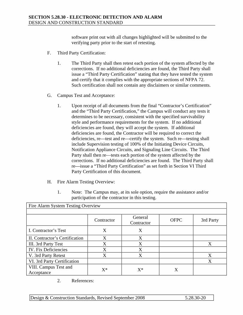
H. Fire Alarm Testing Overview:
1. Note: The Campus may, at its sole option, require the assistance and/or participation of the contractor in this testing.
Fire Alarm System Testing Overview
Contractor General Contractor OFPC 3rd Party
I. Contractor’s Test X X II. Contractor’s Certification X X III. 3rd Party Test X X X IV. Fix Deficiencies X X V. 3rd Party Retest X X X VI. 3rd Party Certification X VIII. Campus Test and Acceptance X* X* X
2. References:
Design & Construction Standards, Revised September 2008 5.28.30-20
SECTION 5.28.30 - ELECTRONIC DETECTION AND ALARM DESIGN AND CONSTRUCTION STANDARD
a. Texas Administrative Code, Title 28. Insurance, Part 1. Texas Department of Insurance, Chapter 34. State Fire Marshal, Subchapter F. Fire Alarm Rules.
b. National Fire Alarm Code (NFPA 72), 2002 edition
PART 6 DOCUMENTATION
6.01 General
A. A documentation package must be provided by the Contractor before final testing with FSSS and FPS AHJ that shall include all information needed to allow the University to perform additions, modifications, maintenance and repair of the system.
B. This must include:
1. Equipment schematic diagrams for all components and modules.
2. Equipment technical data.
3. Field device address register.
4. Equipment repair parts lists.
5. Programming disk with all system software required for a re-start after traumatic failure. Software must be of appropriate and compatible update version for the firmware installed including hardware key, if required.
C. "As-built " wiring, conduit diagrams to include:
1. Floor plan layout drawings showing all significant conduit routes and sizes, wire amounts, sizes and color code and marshaling box locations.
2. Riser diagram showing all significant conduit routes and sizes, wire amounts, sizes and color code and marshaling box locations.
D. Floor plan device layout drawing to include:
1. All initiating device locations and digital addresses.
2. All notification appliance locations and NAC digital addresses or device number.
3. All control device locations and digital addresses.
4. All monitor device locations for supervisory switch groups.
5. All distributed power supply locations and digital addresses.
Design & Construction Standards, Revised September 2008 5.28.30-21
SECTION 5.28.30 - ELECTRONIC DETECTION AND ALARM DESIGN AND CONSTRUCTION STANDARD
6. Schematic representation of all SLCs, NACs, control circuits, audio circuits and power circuits.
E. Riser diagram to include:
1. All initiating devices with their electrical location and digital address on the SLC.
2. All notification appliances with their electrical location and device number or digital address on the SLC.
3. All control devices with their electrical location and digital address on the SLC.
4. All supervisory switch locations and their interconnection to the monitor device (IDCs).
5. All monitor devices with their electrical location and digital address on the SLC.
6. All distributed power supplies with their associated wiring and digital address(es) on the SLC.
7. Schematic representation of all SLCs, NACs, audio circuits and power circuits.
F. Interconnection diagram(s) for all internal components of the Fire Alarm Control Panel, including switch settings, jumpers, module addresses, and Terminations on drawings.
G. State of Texas or NFPA certification form.
H. Programming guide for the functional programming to provide for field changes to the zone schedule or other operational features.
I. Backup copy of the operating system and/or all resident programming, software or firmware, which would be required to restore the system to full operation after a complete failure or equipment replacement.
J. A system hardware component capable of storing and transporting the above listed programming and operating systems and reports.
K. Provide factory logging software for periodic testing.
6.02 Warranty
6.03 Warranty and Maintenance
Design & Construction Standards, Revised September 2008 5.28.30-22
SECTION 5.28.30 - ELECTRONIC DETECTION AND ALARM DESIGN AND CONSTRUCTION STANDARD
A. The contractor shall warranty all materials, installation and workmanship for three (3) years from date of acceptance by the University of Texas, unless otherwise specified. A copy of the manufacturer's warranty shall be provided with closeout documentation and included with the operation and installation manuals.
B. Materials, installation or workmanship found to be defective during that period shall be replaced without cost to the University of Texas. This Contractor shall initiate repair of any warranty defects within 8 hours of notification of such defects and shall be repaired within 24 hours.
C. The warranty or any part of the warranty shall not be made void by any required operation or inspection of the system after acceptance during the warranty period. The University of Texas will use University of Texas personnel to provide required tests and inspections.
D. If the Owner experiences more than two Nuisance alarms or unexplained false alarms or troubles in any 24-hour period while the system is under warranty, the Contractor shall provide the necessary labor, materials, and technical expertise to promptly correct the problem(s) at no cost to the University of Texas.
E. The fire alarm contractor shall maintain a service organization with adequate spare parts stock within 75 miles of the installation.
F. Spare Parts - The Contractor shall supply the following spare parts:
1. Automatic detection devices - Two (2) percent of the installed quantity of each type.
2. Manual fire alarm stations - Two (2) percent of the installed quantity of each type.
3. Modules - Two (2) percent of the installed quantity of each type.
4. Audible and visible devices - One (1) percent of the installed quantity of each type and color, but no less than two (2) devices.
5. Keys - A minimum of three (3) sets of keys shall be provided and appropriately identified.
6.04 Training
Design & Construction Standards, Revised September 2008 5.28.30-23
SECTION 5.28.30 - ELECTRONIC DETECTION AND ALARM DESIGN AND CONSTRUCTION STANDARD
A. Provide services of manufacturer's representative to instruct Owner's personnel in operation and maintenance of system for a minimum of two 4 hour sessions.
B. Factory training at the expense of the Fire alarm contractor for two UT FSSS
personnel is required for the installed system.
END OF STANDARD
Design & Construction Standards, Revised September 2008 5.28.30-24