Embed Size (px)
Citation preview
Toyota Brake Systems - Course 552 73
Diagnosing a problem in the brake system is similar to diagnosing
problems in any other system in the vehicle. The plan of action should
include the following:
• verify the customers complaint.
• identify the symptoms.
• isolate the cause.
• repair the problem.
• check for proper operation.
Begin by determining the symptoms based on the customer’s complaint
recorded on the RO. If your information is incomplete and you proceed
to fix what you find to be a problem, other than what the customer
complained about, you both lose. The customer has to bring the car
back and you may not get paid for the work you did.
You’re the expert, the customer brings the vehicle in because they
perceive a problem. When you service the vehicle and don’t take care of
the problem, you look bad and so does the dealer. Worst of all, the
customer may not return. So get more information when in doubt.
If you can’t verify the customer’s complaint, it may be necessary to go
for a test drive with the customer so that he can point out the
symptom. The problem may not be brakes at all. It could be something
as simple as a bowling ball in the trunk that makes a banging noise
when the brakes are hit hard, or it could be a loose suspension
component or worn bushings.
Attempt to find the source of the customer’s complaint: then any
additional things you find to be improper can be brought to the
customer’s attention for their approval to repair.
Chances are you have done a previous repair for a similar symptom.
That gives you an advantage in your diagnosis.
Before you take the customer’s car out for a test drive, make sure it’s
safe. If the pedal goes to the floor sometimes but seems fine now, do
some preliminary checks before you take it out on the road.
Section 7
BRAKE DIAGNOSIS
DiagnosingBrake Problems
Verify CustomersComplaint
Section 7
74 TOYOTA Technical Training
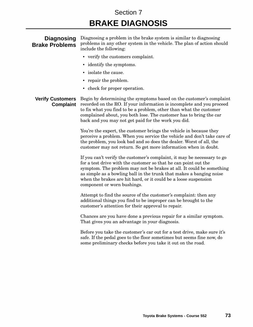
Preliminary checks should establish that the essentials are intact and
operational. Check fluid level in the master cylinder. Even though it is
full, check for leaks, the reservoir may have been topped off prior to
bringing it in for service. Check the following for signs of leakage:
• brake backing plate.
• flexible brake hoses.
• connections.
• brake tubing.
• auxiliary valves.
• master cylinder.
Brake SystemInspection
Check for leakage at thebrake backing plate, flexible
brake hoses, connections,brake tubing, auxiliary valves
and the master cylinder.
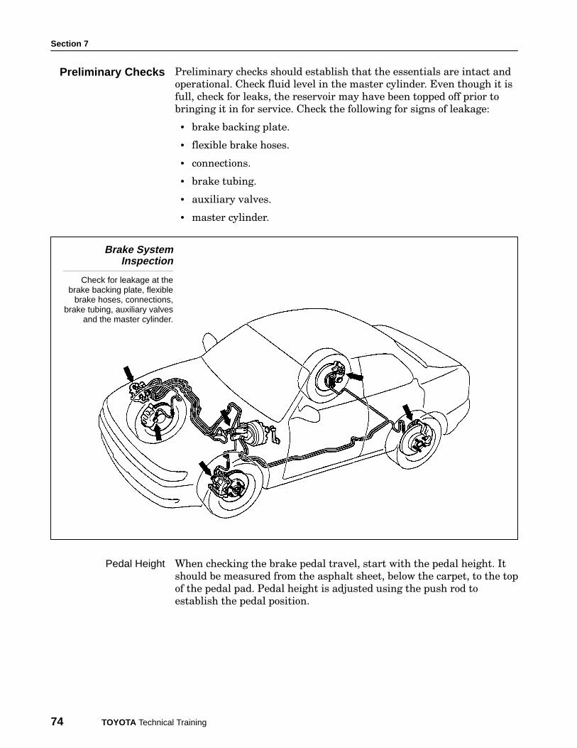
When checking the brake pedal travel, start with the pedal height. It
should be measured from the asphalt sheet, below the carpet, to the top
of the pedal pad. Pedal height is adjusted using the push rod to
establish the pedal position.
Preliminary Checks
Pedal Height
Brake Diagnosis
Toyota Brake Systems - Course 552 75
Brake Pedal Height
Measured from the asphaltsheet, below the carpet,
to the top of the pedalpad. Adjusted using the
push rod and clevis.
Make sure that the freeplay is at least 0.040" to 0.120" (1 − 3 mm).
Turn the engine off and apply the brakes several times to reduce the
vacuum in the booster. If freeplay is less than specified, the brakes may
be lightly applied at all times, overheating the brakes and causing
premature wear. If there is too little free play, check the Stop Light
Switch for proper clearance as shown below.
Brake Pedal Freeplay
Turn the engine offand apply the brakes
several times to reduce thevacuum in the booster.
Pedal Freeplay
Section 7
76 TOYOTA Technical Training
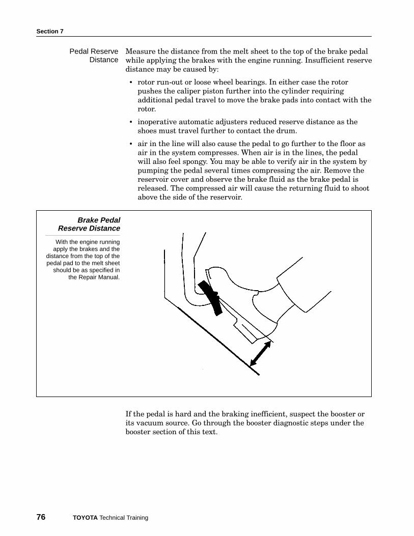
Measure the distance from the melt sheet to the top of the brake pedal
while applying the brakes with the engine running. Insufficient reserve
distance may be caused by:
• rotor run−out or loose wheel bearings. In either case the rotor
pushes the caliper piston further into the cylinder requiring
additional pedal travel to move the brake pads into contact with the
rotor.
• inoperative automatic adjusters reduced reserve distance as the
shoes must travel further to contact the drum.
• air in the line will also cause the pedal to go further to the floor as
air in the system compresses. When air is in the lines, the pedal
will also feel spongy. You may be able to verify air in the system by
pumping the pedal several times compressing the air. Remove the
reservoir cover and observe the brake fluid as the brake pedal is
released. The compressed air will cause the returning fluid to shoot
above the side of the reservoir.
Brake PedalReserve Distance
With the engine runningapply the brakes and the
distance from the top of thepedal pad to the melt sheet
should be as specified inthe Repair Manual.
If the pedal is hard and the braking inefficient, suspect the booster or
its vacuum source. Go through the booster diagnostic steps under the
booster section of this text.
Pedal ReserveDistance
Brake Diagnosis
Toyota Brake Systems - Course 552 77
Worn pads or shoes may be quite obvious, but when you look closely
and compare the wear side to side it may give you a clue as to their
operation. If pads on one side are worn more severely than the opposite
side of the vehicle, the piston may be stuck in the cylinder of the
opposite caliper. If the inside pad is worn more severely than the
outside pad of the same brake assembly, the caliper may not be free to
float on the torque plate.
Areas not directly related to the brake system should be inspected as
they may indirectly cause noise or pull when the brakes are applied.
Tire condition and inflation pressure should be considered. The
pressure and tire size should be equal from side to side on the same
axle. Tire condition may indicate front suspension problems.
When excessive wheel and tire run−out is present a vibration may be
felt on brake application. Check the vehicle Repair Manual for the
specific run−out specification. Vibration may also be felt at cruise
speeds. For example, it may come in at 55 mph and be gone at 60 mph.
Worn suspension bushings or ball joints change front−end geometry
and may cause a pull or drift when the brakes are applied.
A road test should be completed in order to verify the customer’s
complaint. Because the customer perceives the problem when the
brakes are applied, he naturally assumes the problem to be in the
brakes. However, the brake system may be indirectly related to the
complaint. It is important to determine the correct cause of the
customer concern.
A series of decelerations from 50 to 20 mph, while noting the vehicle
speed, intensity and location of any vibration will aid in further
diagnosis of the system.
The first check is done merely by allowing the vehicle to coast down
without applying the brakes to determine if the problem lies outside
the brake system.
This will help to determine if driveshaft balance or angle is causing a
vibration. If the vibration occurs at speeds between 40 to 25 mph, the
problem is likely that the driveshaft angle varies at each end of the
driveshaft. This can be confirmed by noting any vibration on moderate
to heavy acceleration.
The second check involves applying light to moderate brake pressure.
Information found here is used in conjunction with parking brake
application to determine the area of vibration.
If the symptom occurs when the service brake is applied and not when
the parking brake is applied, the problem lies in the front brake or
wheel assemblies.
Brake Pad Inspection
Suspension Inspection
Road Test - Identifythe Symptoms
Section 7
78 TOYOTA Technical Training
When vibration is most noticeable in the steering wheel, check the
front brakes, wheel and tire condition. When vibration is most
noticeable in the brake pedal, check disc rotor for parallelism. Measure
the disc thickness at eight points around the circumference, about 10
mm from the outside edge.
The third check is done by using the parking brake. This check can
only be done with those vehicles which share the service and parking
brake assemblies. It distinguishes vibration caused by front and rear
brake assemblies.
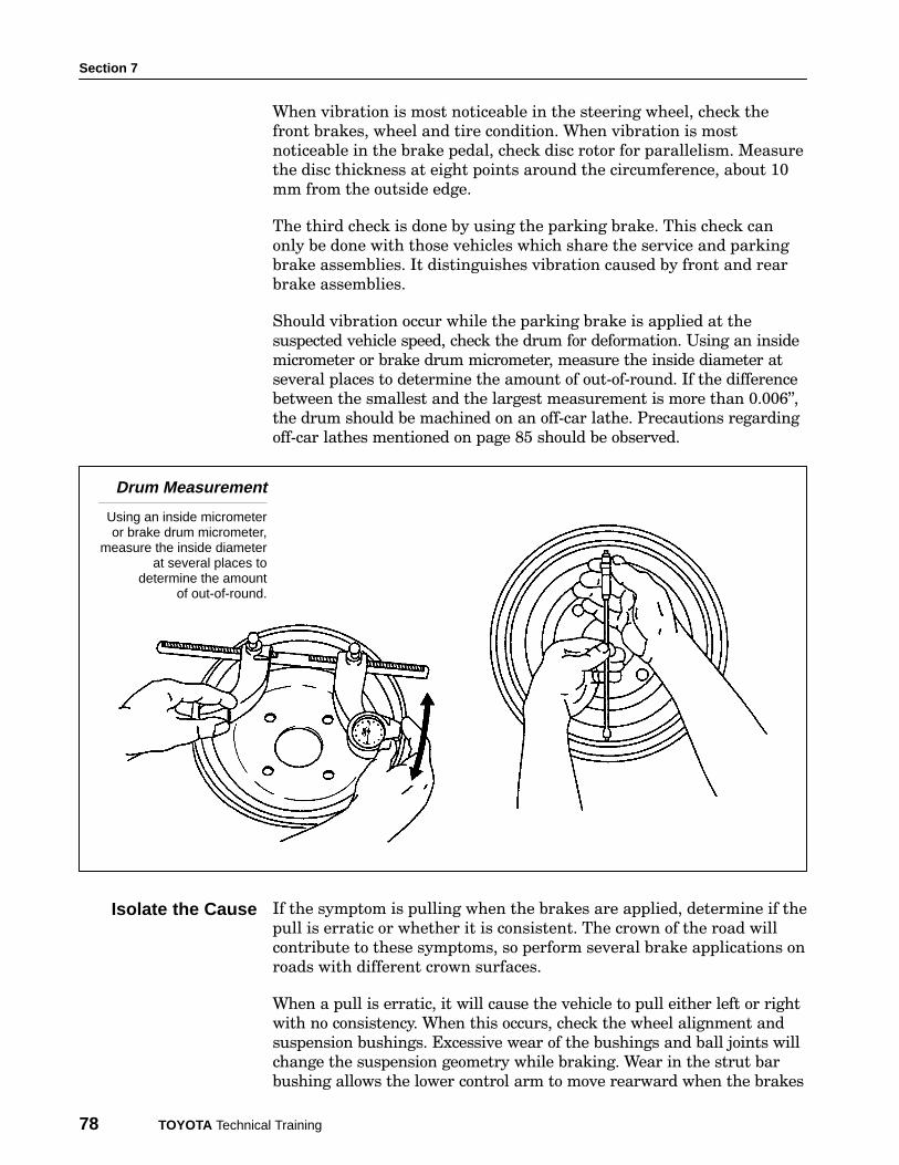
Should vibration occur while the parking brake is applied at the
suspected vehicle speed, check the drum for deformation. Using an inside
micrometer or brake drum micrometer, measure the inside diameter at
several places to determine the amount of out−of−round. If the difference
between the smallest and the largest measurement is more than 0.006",
the drum should be machined on an off−car lathe. Precautions regarding
off−car lathes mentioned on page 85 should be observed.
Drum Measurement
Using an inside micrometeror brake drum micrometer,
measure the inside diameterat several places to
determine the amountof out-of-round.
If the symptom is pulling when the brakes are applied, determine if the
pull is erratic or whether it is consistent. The crown of the road will
contribute to these symptoms, so perform several brake applications on
roads with different crown surfaces.
When a pull is erratic, it will cause the vehicle to pull either left or right
with no consistency. When this occurs, check the wheel alignment and
suspension bushings. Excessive wear of the bushings and ball joints will
change the suspension geometry while braking. Wear in the strut bar
bushing allows the lower control arm to move rearward when the brakes
Isolate the Cause

Brake Diagnosis
Toyota Brake Systems - Course 552 79
are applied, inducing caster change which causes a pull. Caster will
cause a vehicle to pull to the side of the least positive caster.
A steering gear that is out of adjustment or loose in its mounting may
also contribute to an erratic pull.
When the vehicle pulls consistently in one direction, the problem is
usually in the brake system. When the pull is to the left for example,
check both the left and right brake assemblies. The cause of a greater
amount of braking on one side may be a condition on either brake
assembly. Inspection of the brake system should start with the
condition of the brake drum or disc surface. The surface condition
should be the same on both rotors.
Lining that is soaked with brake fluid or gear oil will cause a pull and
should be replaced as an axle set after repairing the source of the leak.
The brake assembly creating the greatest heat conversion will do the
greatest braking. So when a caliper is frozen on the torque plate or a
piston is frozen in the caliper, the vehicle will pull to the opposite side.
Brake noise is caused by friction between the pads and drum or rotor
when the brakes are applied. Occasional squeal is normal, and not a
functional problem and does not indicate loss of braking effectiveness.
When the brake noise occurs all the time, check the lining condition.
Lining that is glazed should be replaced or cleaned using emery cloth.
When sanding the lining to remove the glazed surface, be sure to cover
the entire surface evenly. (See precautions under asbestos in the
reference section of this book). Also check the drum or disc for a glazed
condition and cleanup with emery cloth or turn on a brake lathe if the
drum diameter or disc thickness permits.
Squeal can also be caused by a weak or broken hold down spring or
return spring as well as missing, damaged or improperly installed
anti−squeal shims. To inspect return springs, check for space between
the spring coils and nicks in the spring wire diameter. Nicks caused by
tools during installation and removal may cause springs to break.
Damaged springs should be replaced as a set.
Anti−squeal shims help to dampen the vibration which occurs when the
pads contact the disc. Make sure that the appropriate shims are in
place. Anti−rattle springs are used to position and hold the pad as
rigidly as possible to reduce pad movement in the caliper assembly and
thereby reduce noise caused by vibration. Make sure that they are
positioned properly so they are most effective.
Brake Noise
Section 7
80 TOYOTA Technical Training
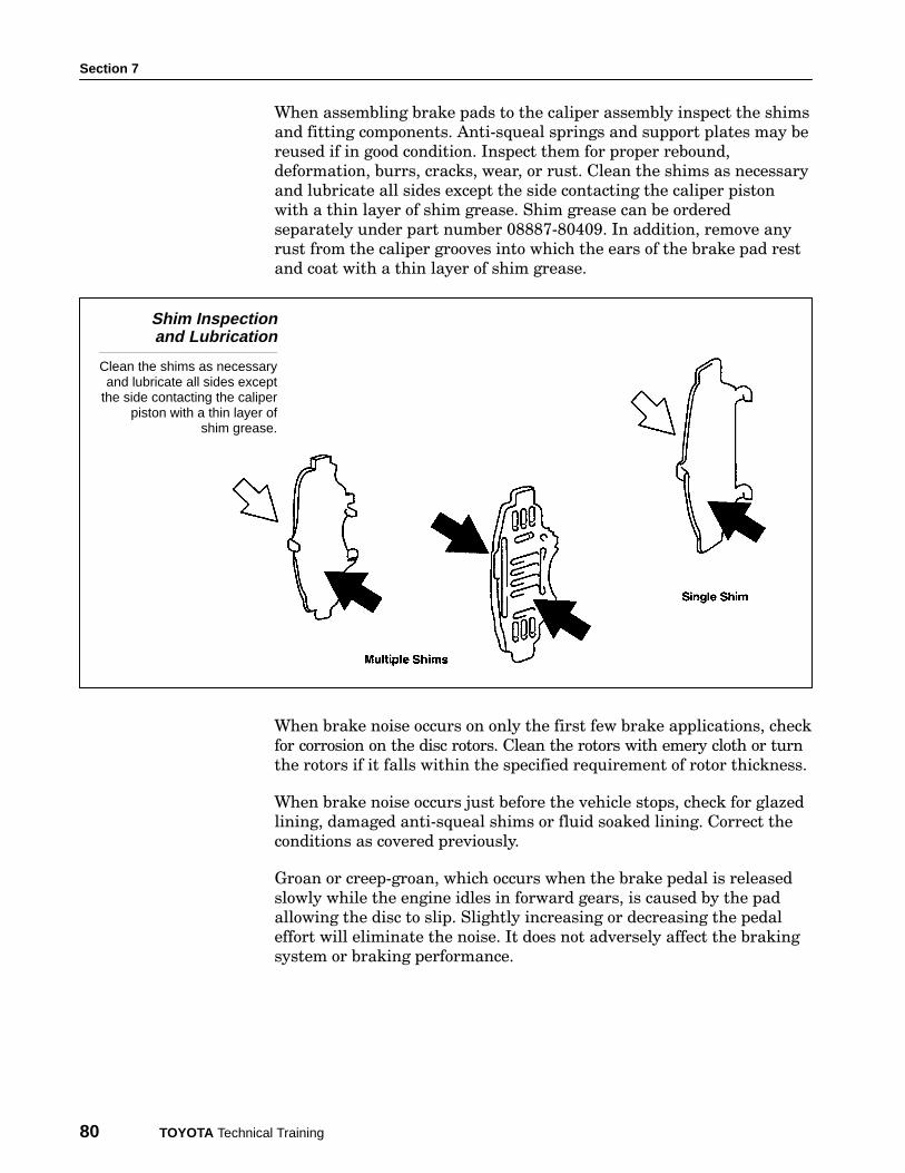
When assembling brake pads to the caliper assembly inspect the shims
and fitting components. Anti−squeal springs and support plates may be
reused if in good condition. Inspect them for proper rebound,
deformation, burrs, cracks, wear, or rust. Clean the shims as necessary
and lubricate all sides except the side contacting the caliper piston
with a thin layer of shim grease. Shim grease can be ordered
separately under part number 08887−80409. In addition, remove any
rust from the caliper grooves into which the ears of the brake pad rest
and coat with a thin layer of shim grease.
Shim Inspectionand Lubrication
Clean the shims as necessaryand lubricate all sides except
the side contacting the caliperpiston with a thin layer of
shim grease.
When brake noise occurs on only the first few brake applications, check
for corrosion on the disc rotors. Clean the rotors with emery cloth or turn
the rotors if it falls within the specified requirement of rotor thickness.
When brake noise occurs just before the vehicle stops, check for glazed
lining, damaged anti−squeal shims or fluid soaked lining. Correct the
conditions as covered previously.
Groan or creep−groan, which occurs when the brake pedal is released
slowly while the engine idles in forward gears, is caused by the pad
allowing the disc to slip. Slightly increasing or decreasing the pedal
effort will eliminate the noise. It does not adversely affect the braking
system or braking performance.
Brake Diagnosis
Toyota Brake Systems - Course 552 81
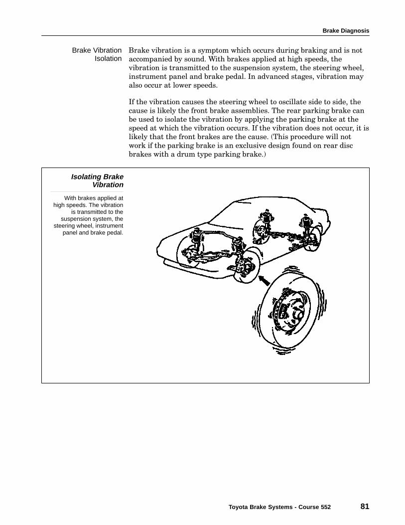
Brake vibration is a symptom which occurs during braking and is not
accompanied by sound. With brakes applied at high speeds, the
vibration is transmitted to the suspension system, the steering wheel,
instrument panel and brake pedal. In advanced stages, vibration may
also occur at lower speeds.
If the vibration causes the steering wheel to oscillate side to side, the
cause is likely the front brake assemblies. The rear parking brake can
be used to isolate the vibration by applying the parking brake at the
speed at which the vibration occurs. If the vibration does not occur, it is
likely that the front brakes are the cause. (This procedure will not
work if the parking brake is an exclusive design found on rear disc
brakes with a drum type parking brake.)
Isolating BrakeVibration
With brakes applied athigh speeds. The vibration
is transmitted to thesuspension system, the
steering wheel, instrumentpanel and brake pedal.
Brake VibrationIsolation
Section 7
82 TOYOTA Technical Training
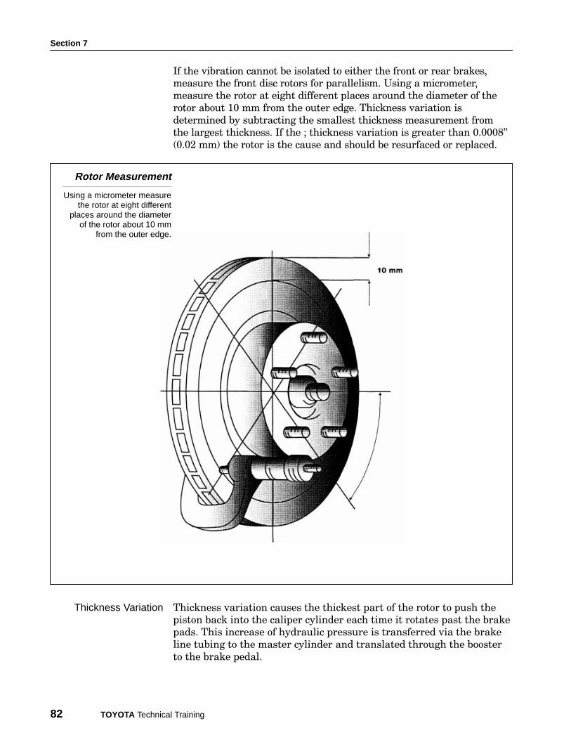
If the vibration cannot be isolated to either the front or rear brakes,
measure the front disc rotors for parallelism. Using a micrometer,
measure the rotor at eight different places around the diameter of the
rotor about 10 mm from the outer edge. Thickness variation is
determined by subtracting the smallest thickness measurement from
the largest thickness. If the ; thickness variation is greater than 0.0008"
(0.02 mm) the rotor is the cause and should be resurfaced or replaced.
Rotor Measurement
Using a micrometer measurethe rotor at eight different
places around the diameterof the rotor about 10 mm
from the outer edge.
Thickness variation causes the thickest part of the rotor to push the
piston back into the caliper cylinder each time it rotates past the brake
pads. This increase of hydraulic pressure is transferred via the brake
line tubing to the master cylinder and translated through the booster
to the brake pedal.
Thickness Variation
Brake Diagnosis
Toyota Brake Systems - Course 552 83
Two conditions that cause thickness variation are:
• Rotor run−out.
• Excessive rust or corrosion on rotor surface.
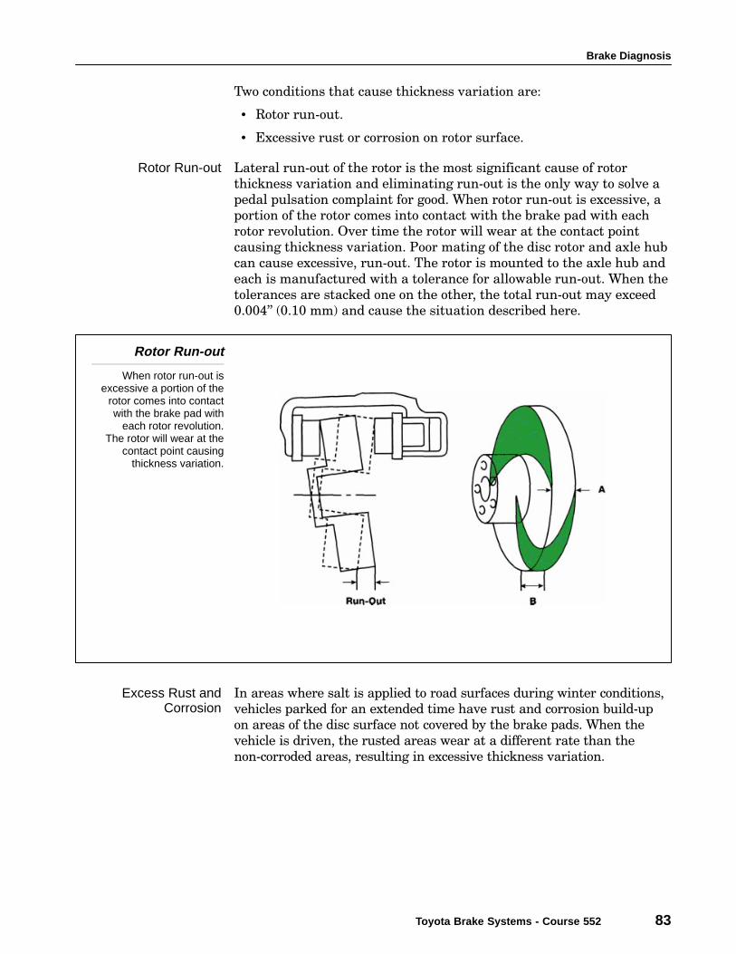
Lateral run−out of the rotor is the most significant cause of rotor
thickness variation and eliminating run−out is the only way to solve a
pedal pulsation complaint for good. When rotor run−out is excessive, a
portion of the rotor comes into contact with the brake pad with each
rotor revolution. Over time the rotor will wear at the contact point
causing thickness variation. Poor mating of the disc rotor and axle hub
can cause excessive, run−out. The rotor is mounted to the axle hub and
each is manufactured with a tolerance for allowable run−out. When the
tolerances are stacked one on the other, the total run−out may exceed
0.004" (0.10 mm) and cause the situation described here.
Rotor Run-out
When rotor run-out isexcessive a portion of the
rotor comes into contactwith the brake pad with
each rotor revolution.The rotor will wear at the
contact point causingthickness variation.
In areas where salt is applied to road surfaces during winter conditions,
vehicles parked for an extended time have rust and corrosion build−up
on areas of the disc surface not covered by the brake pads. When the
vehicle is driven, the rusted areas wear at a different rate than the
non−corroded areas, resulting in excessive thickness variation.
Rotor Run-out
Excess Rust andCorrosion

Section 7
84 TOYOTA Technical Training
Resurfacing of rotors with an on−car brake lathe is the recommended
operation to correct rotor run−out and thickness variation. The on−car
lathe is installed in the same position as the caliper, ensuring that the
rotors will be machined absolutely parallel to the brake pad and caliper
assembly. An on−car lathe is designed to take into account all of the
variations in the bearings, hub and rotor assembly and provides the
greatest accuracy by eliminating virtually all run−out.
On-Car Brake Lathe
The on-car lathe isinstalled in the same
position as the caliper,ensuring that the rotors
will be machined absolutelyparallel to the brake pad and
caliper assembly.
Repair the Problem
Brake Diagnosis
Toyota Brake Systems - Course 552 85
If an on−car lathe is not available and the rotor is machined on an
off−car lathe:
• check the lathe arbor for excessive run−out and correct or replace as
needed.
• check the condition of the rotor mounting surfaces to ensure proper
mounting.
• make certain the adapters and cones are free of burs and particles
that might prevent the proper mounting of the rotor.
• check the rotor run−out with a dial indicator and correct mounting
as needed.
• measure the rotor thickness to ensure it is greater than the
minimum thickness.
Typically when a rotor is turned on a lathe, the opposite rotor should
also be turned so that they are both within 0.010" (0.25 mm) of each
other. Also, if one rotor has a rougher surface finish than the other, the
difference in friction may cause a pull.
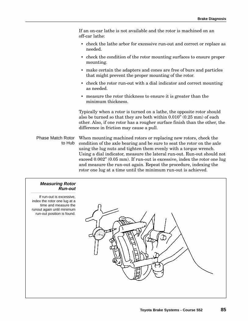
When mounting machined rotors or replacing new rotors, check the
condition of the axle bearing and be sure to seat the rotor on the axle
using the lug nuts and tighten them evenly with a torque wrench.
Using a dial indicator, measure the lateral run−out. Run−out should not
exceed 0.002" (0.05 mm). If run−out is excessive, index the rotor one lug
and measure the run−out again. Repeat the procedure, indexing the
rotor one lug at a time until the minimum run−out is achieved.
Measuring RotorRun-out
If run-out is excessive,index the rotor one lug at a
time and measure therunout again until minimum
run-out position is found.
Phase Match Rotorto Hub
Section 7
86 TOYOTA Technical Training
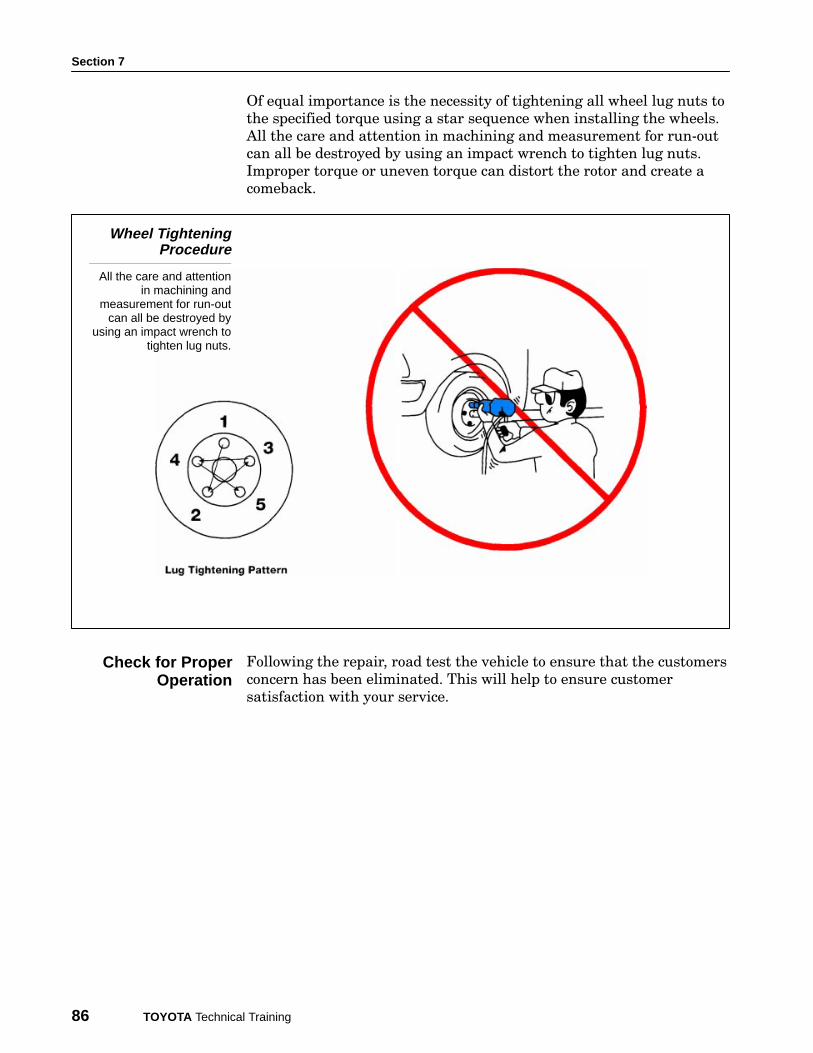
Of equal importance is the necessity of tightening all wheel lug nuts to
the specified torque using a star sequence when installing the wheels.
All the care and attention in machining and measurement for run−out
can all be destroyed by using an impact wrench to tighten lug nuts.
Improper torque or uneven torque can distort the rotor and create a
comeback.
Wheel TighteningProcedure
All the care and attentionin machining and
measurement for run-outcan all be destroyed by
using an impact wrench totighten lug nuts.
Following the repair, road test the vehicle to ensure that the customers
concern has been eliminated. This will help to ensure customer
satisfaction with your service.
Check for ProperOperation
Brake Diagnosis
Toyota Brake Systems - Course 552 87
WORKSHEET 7-1 (ON-CAR)Brake Rotor Run-Out and Rotor Phase Matching
Vehicle Year/Prod. Date Engine Transmission
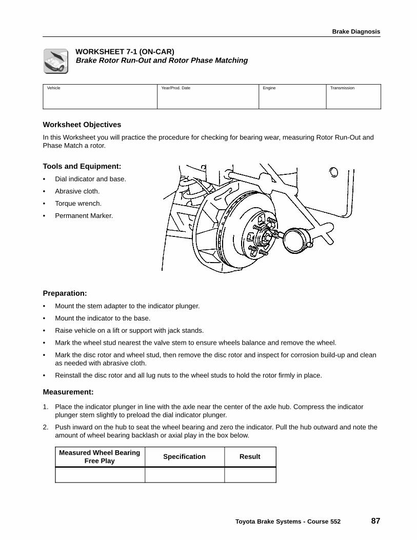
Worksheet Objectives
In this Worksheet you will practice the procedure for checking for bearing wear, measuring Rotor Run-Out andPhase Match a rotor.
Tools and Equipment:
• Dial indicator and base.
• Abrasive cloth.
• Torque wrench.
• Permanent Marker.
Preparation:
• Mount the stem adapter to the indicator plunger.
• Mount the indicator to the base.
• Raise vehicle on a lift or support with jack stands.
• Mark the wheel stud nearest the valve stem to ensure wheels balance and remove the wheel.
• Mark the disc rotor and wheel stud, then remove the disc rotor and inspect for corrosion build-up and cleanas needed with abrasive cloth.
• Reinstall the disc rotor and all lug nuts to the wheel studs to hold the rotor firmly in place.
Measurement:
1. Place the indicator plunger in line with the axle near the center of the axle hub. Compress the indicatorplunger stem slightly to preload the dial indicator plunger.
2. Push inward on the hub to seat the wheel bearing and zero the indicator. Pull the hub outward and note theamount of wheel bearing backlash or axial play in the box below.
Measured Wheel BearingFree Play
Specification Result
Section 7
88 TOYOTA Technical Training
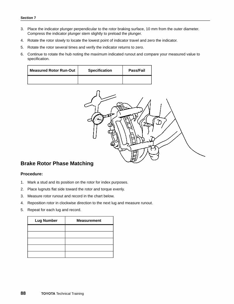
3. Place the indicator plunger perpendicular to the rotor braking surface, 10 mm from the outer diameter.Compress the indicator plunger stem slightly to preload the plunger.
4. Rotate the rotor slowly to locate the lowest point of indicator travel and zero the indicator.
5. Rotate the rotor several times and verify the indicator returns to zero.
6. Continue to rotate the hub noting the maximum indicated runout and compare your measured value tospecification.
Measured Rotor Run-Out Specification Pass/Fail
Brake Rotor Phase Matching
Procedure:
1. Mark a stud and its position on the rotor for index purposes.
2. Place lugnuts flat side toward the rotor and torque evenly.
3. Measure rotor runout and record in the chart below.
4. Reposition rotor in clockwise direction to the next lug and measure runout.
5. Repeat for each lug and record.
Lug Number Measurement
Brake Diagnosis
Toyota Brake Systems - Course 552 89
Summary:
1. How could excessive wheel bearing free play influence runout measured at the brake rotor?
2. How could excessive wheel bearing free play affect brake pedal travel?
3. What affect would a rotor with excess runout have on brake operation in the first 500 miles?
4. What happened to the rotor in question 3 if after several thousand miles of wear, the brake pedal pulsates?
5. What is the proper service procedure to correct the condition identified in question 4?
6. Referring to the measurements made for Phase Matching, what is the difference between the highest runoutand the lowest runout? (Show your math calculations)

Section 7
90 TOYOTA Technical Training
Brake Diagnosis
Toyota Brake Systems - Course 552 91
WORKSHEET 7-2 (ON-CAR)Brake Rotor Parallelism Measurement
Vehicle Year/Prod. Date Engine Transmission
Worksheet Objectives
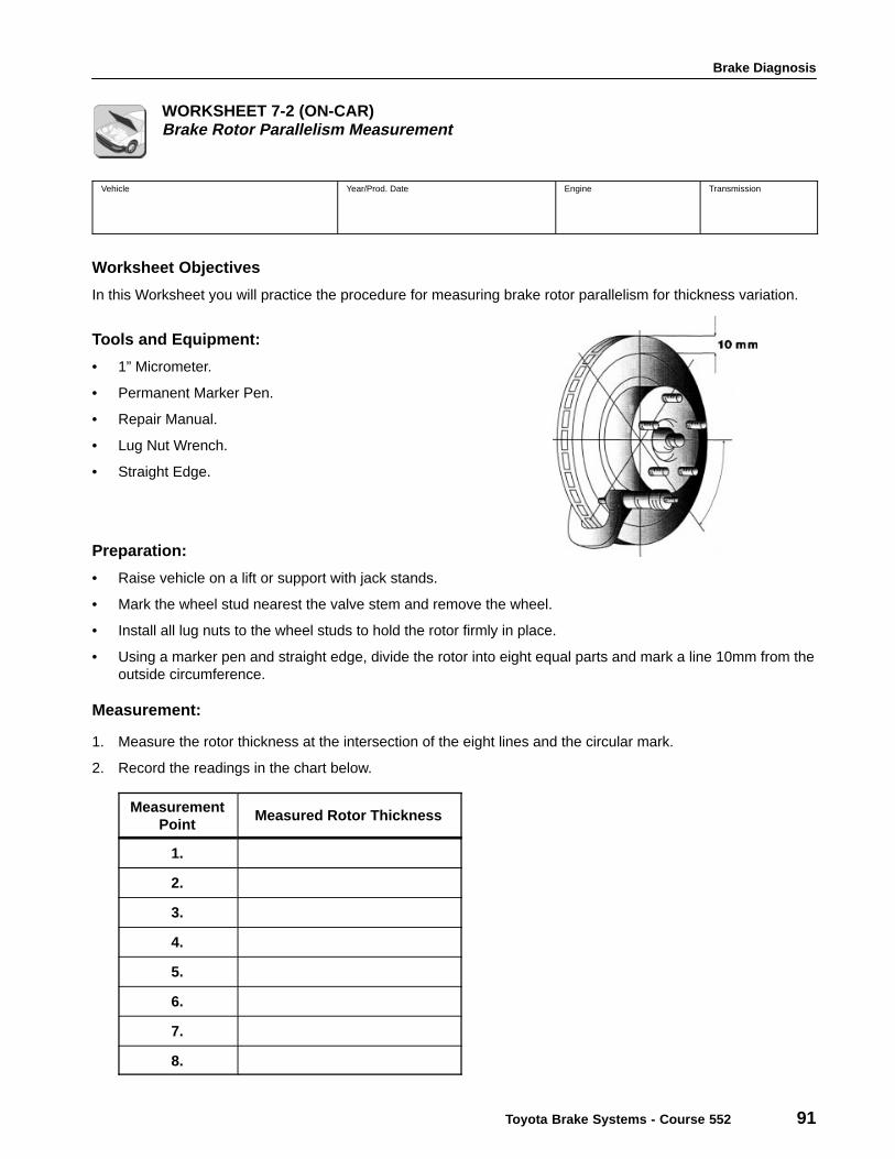
In this Worksheet you will practice the procedure for measuring brake rotor parallelism for thickness variation.
Tools and Equipment:
• 1” Micrometer.
• Permanent Marker Pen.
• Repair Manual.
• Lug Nut Wrench.
• Straight Edge.
Preparation:
• Raise vehicle on a lift or support with jack stands.
• Mark the wheel stud nearest the valve stem and remove the wheel.
• Install all lug nuts to the wheel studs to hold the rotor firmly in place.
• Using a marker pen and straight edge, divide the rotor into eight equal parts and mark a line 10mm from theoutside circumference.
Measurement:
1. Measure the rotor thickness at the intersection of the eight lines and the circular mark.
2. Record the readings in the chart below.
MeasurementPoint
Measured Rotor Thickness
1.
2.
3.
4.
5.
6.
7.
8.
Section 7
92 TOYOTA Technical Training
Measurement (Cont’d):
3. Record the largest and smallest thickness measurement in the chart and record the thickness variation.
ÁÁÁÁÁÁÁÁÁÁÁÁÁÁÁÁÁÁÁÁÁÁÁÁ
LargestÁÁÁÁÁÁÁÁÁÁÁÁÁÁÁÁÁÁÁÁÁÁÁÁÁÁÁÁÁÁÁÁ
ÁÁÁÁÁÁÁÁSmallest ÁÁÁÁÁÁÁÁ
ÁÁÁÁÁÁÁÁÁÁÁÁÁÁÁÁÁÁÁÁÁÁÁÁÁÁÁÁÁÁÁÁ
Thickness VariationÁÁÁÁÁÁÁÁÁÁÁÁÁÁÁÁÁÁÁÁÁÁÁÁÁÁÁÁÁÁÁÁ
ÁÁÁÁÁÁÁÁÁÁÁÁÁÁÁÁ
Rotor MinimumThickness
ÁÁÁÁÁÁÁÁÁÁÁÁÁÁÁÁÁÁÁÁÁÁÁÁ
Summary:
1. What is the specification for maximum allowable thickness variation?
2. What symptoms would be experienced with excessive thickness variation?
3. List two causes of rotor thickness variation?
4. What is the correct repair procedure for thickness variation?
Brake Diagnosis
Toyota Brake Systems - Course 552 93
WORKSHEET 7-3 (ON-CAR)On-Car Brake Lathe
Vehicle Year/Prod. Date Engine Transmission
Worksheet Objectives
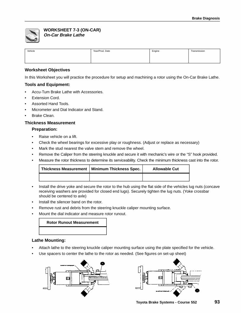
In this Worksheet you will practice the procedure for setup and machining a rotor using the On-Car Brake Lathe.
Tools and Equipment:
• Accu-Tum Brake Lathe with Accessories.
• Extension Cord.
• Assorted Hand Tools.
• Micrometer and Dial Indicator and Stand.
• Brake Clean.
Thickness MeasurementPreparation:
• Raise vehicle on a lift.
• Check the wheel bearings for excessive play or roughness. (Adjust or replace as necessary)
• Mark the stud nearest the valve stem and remove the wheel.
• Remove the Caliper from the steering knuckle and secure it with mechanic’s wire or the “S” hook provided.
• Measure the rotor thickness to determine its serviceability. Check the minimum thickness cast into the rotor.
Thickness Measurement Minimum Thickness Spec. Allowable Cut
• Install the drive yoke and secure the rotor to the hub using the flat side of the vehicles lug nuts (concavereceiving washers are provided for closed end lugs). Securely tighten the lug nuts. (Yoke crossbarshould be centered to axle)
• Install the silencer band on the rotor.
• Remove rust and debris from the steering knuckle caliper mounting surface.
• Mount the dial indicator and measure rotor runout.
Rotor Runout Measurement
Lathe Mounting:
• Attach lathe to the steering knuckle caliper mounting surface using the plate specified for the vehicle.
• Use spacers to center the lathe to the rotor as needed. (See figures on set-up sheet)
Section 7
94 TOYOTA Technical Training
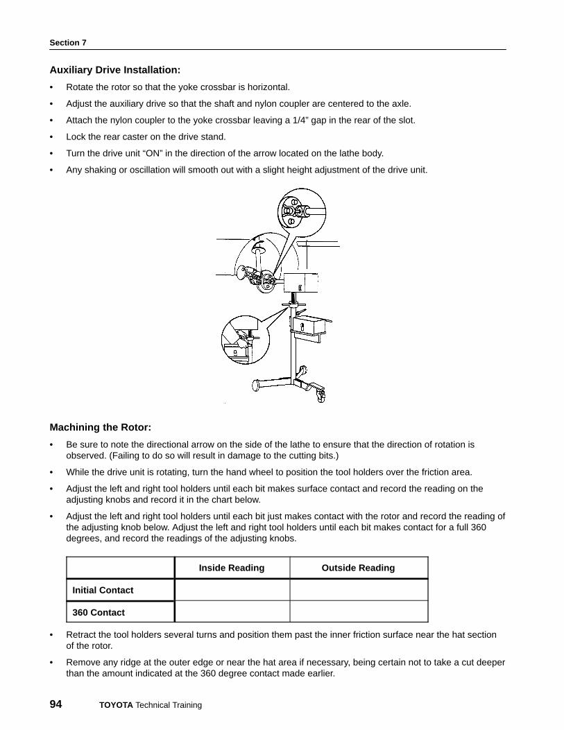
Auxiliary Drive Installation:
• Rotate the rotor so that the yoke crossbar is horizontal.
• Adjust the auxiliary drive so that the shaft and nylon coupler are centered to the axle.
• Attach the nylon coupler to the yoke crossbar leaving a 1/4” gap in the rear of the slot.
• Lock the rear caster on the drive stand.
• Turn the drive unit “ON” in the direction of the arrow located on the lathe body.
• Any shaking or oscillation will smooth out with a slight height adjustment of the drive unit.
Machining the Rotor:
• Be sure to note the directional arrow on the side of the lathe to ensure that the direction of rotation isobserved. (Failing to do so will result in damage to the cutting bits.)
• While the drive unit is rotating, turn the hand wheel to position the tool holders over the friction area.
• Adjust the left and right tool holders until each bit makes surface contact and record the reading on theadjusting knobs and record it in the chart below.
• Adjust the left and right tool holders until each bit just makes contact with the rotor and record the reading ofthe adjusting knob below. Adjust the left and right tool holders until each bit makes contact for a full 360degrees, and record the readings of the adjusting knobs.
Inside Reading Outside Reading
Initial Contact
360 Contact
• Retract the tool holders several turns and position them past the inner friction surface near the hat sectionof the rotor.
• Remove any ridge at the outer edge or near the hat area if necessary, being certain not to take a cut deeperthan the amount indicated at the 360 degree contact made earlier.

Brake Diagnosis
Toyota Brake Systems - Course 552 95
• Turn the adjusting knobs back to the original reading plus an additional one-half mark (0.002”).
• Push the power feed switch to the rear position.
• Rotate the clutch knob on the handwheel clockwise to engage the feed.
• After machining is complete, measure the rotor thickness to ensure it is above minimum thickness.
Rotor Thickness Measurement
• Mount the dial indicator and measure rotor runout.
Final Rotor Runout Measurement
Summary:
1. Why should wheel bearings be checked for excessive play or roughness before the rotor is turned?
2. Why is it important to torque the lug nuts evenly when securing the brake rotor to the hub before machiningthe rotor.
3. What advantage would there be in providing a non-directional finish on the rotor?
4. When a cut of .002” is made on each side of a rotor, the overall thickness of the rotor is reduced by:
5. What is the difference between the initial rotor thickness measurement and the final thickness measurement?
Section 7
96 TOYOTA Technical Training
![1.2 New ECU diagnosis software with 2009/4 - Shrani.si · 1.2 New ECU diagnosis software with 2009/4 ... Mercedes Benz CLC-class [203] ... SBC (Sensotronic Brake Control) 3](https://img.pdfslide.net/doc/110x75/5b15b0b27f8b9a06298dc414/12-new-ecu-diagnosis-software-with-20094-12-new-ecu-diagnosis-software.jpg)