Embed Size (px)
Citation preview
CORROSION PROTECTION - ALL MODELSSERVICE MANUAL NUMBER 28
90-863160-1 JUNE 2003 Page 7A-1
CORROSION PROTECTIONSection 7A - All Models
Torque Specifications 7A-2. . . . . . . . . . . . . . . . Lubricants / Sealants / Adhesives 7A-2. . . . . Special Tools 7A-2. . . . . . . . . . . . . . . . . . . . . . . . General Information 7A-4. . . . . . . . . . . . . . . . . . Continuity Circuit 7A-5. . . . . . . . . . . . . . . . . . . . Trim Cylinder Anodes 7A-8. . . . . . . . . . . . . . . . Anodic Plate 7A-9. . . . . . . . . . . . . . . . . . . . . . . . .
Bravo One Sterndrive Units 7A-9. . . . . . . . . . Bravo Two Sterndrive Units 7A-11. . . . . . . . . Bravo Three Sterndrive Units 7A-11. . . . . . . .
Integral MerCathode System 7A-12. . . . . . . . . Removing Gimbal Mounted MerCathode Assembly 7A-13. . . . . . . . . . . . . Installing Gimbal Mounted MerCathode System 7A-14. . . . . . . . . . . . . . . Connect to MerCathode Controller Assembly 7A-17. . . . . . . . . . . . . . .
Wiring Diagrams 7A-17. . . . . . . . . . . . . . . . . . . . MerCathode Controller - Standard Models 7A-17. . . . . . . . . . . . . . . . MerCathode Controller - Quick Connect Models 7A-18. . . . . . . . . . .
Galvanic Isolator 7A-18. . . . . . . . . . . . . . . . . . . .
Corrosion Protection Testing andTroubleshooting 7A-19. . . . . . . . . . . . . . . . . . . .
Continuity Test 7A-22. . . . . . . . . . . . . . . . . . . . Test Equipment Set-Up 7A-23. . . . . . . . . . . . . Low Readings 7A-24. . . . . . . . . . . . . . . . . . . . . High Reading 7A-26. . . . . . . . . . . . . . . . . . . . . Normal Reading But Corrosion is Evident 7A-26. . . . . . . . . . . . . . . . . . . . . . . .
Corrosion On The Entire Sterndrive Unit 7A-26. . . . . . . . . . . . . . . . . Corrosion Problem Developed After Refinishing The Sterndrive Unit 7A-26. . . . . . . . . . . . . . . . . Paint Blistering On Sterndrive Unit 7A-26. . . . . . . . . . . . . . . . . Trim Cylinder Corroding 7A-27. . . . . . . . . . Only One Or Two Components Corroding 7A-27. . . . . . . . . . Corrosion In The Exhaust Outlet Area 7A-27. . . . . . . . . . . . . . . . . . . . Corrosion Occurs After The Unit Is Removed From The Water 7A-27. . . . Corrosion Between Surfaces 7A-27. . . . . Aluminum Corroding In Lubricated Areas 7A-27. . . . . . . . . . . . . . . . Stainless Steel Components Corroding 7A-28. . . . . . . . . . Stainless Steel Propeller Corroding 7A-28. . . . . . . . . . . . . Paint Blistering - The Metal Under The Blistered Paint Is Not Pitted 7A-28. . . . . . . . . . . . . . . . . . .
CORROSION PROTECTION - ALL MODELS SERVICE MANUAL NUMBER 28
Page 7A-2 90-863160-1 JUNE 2003
Torque Specifications
NOTE: Securely tighten all fasteners not listed below.
Description Nm lb-in. lb-ft
Anodic plate screw 41 30
MerCathode assembly mounting screws 2.8 25
Lubricants / Sealants / Adhesives
Description Where Used Part Number
Liquid Neoprene All electrical connections 92-25711-3
Mercury Phantom Black Bare metal 92-802878-1
Special Lubricant 101 92-802865A1
2-4-C with Teflon Propeller shaft 92-802859A1
Anti-Corrosion Grease
p
92-802867A1
Special Tools
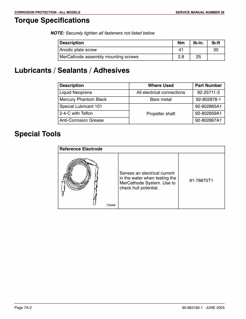
Reference Electrode
73446
Senses an electrical currentin the water when testing theMerCathode System. Use tocheck hull potential.
91-76675T1
CORROSION PROTECTION - ALL MODELSSERVICE MANUAL NUMBER 28
90-863160-1 JUNE 2003 Page 7A-3
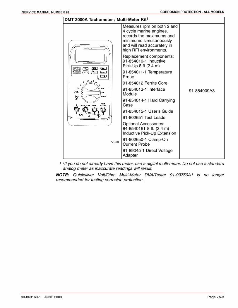
DMT 2000A Tachometer / Multi-Meter Kit1
77959
Measures rpm on both 2 and4 cycle marine engines,records the maximums andminimums simultaneouslyand will read accurately inhigh RFI environments.
Replacement components:91-854010-1 InductivePick-Up 8 ft (2.4 m)
91-854011-1 TemperatureProbe
91-854012 Ferrite Core
91-854013-1 InterfaceModule
91-854014-1 Hard CarryingCase
91-854015-1 User’s Guide
91-802651 Test Leads
Optional Accessories:84-854016T 8 ft. (2.4 m)Inductive Pick-Up Extension
91-802650-1 Clamp-OnCurrent Probe
91-89045-1 Direct VoltageAdapter
91-854009A3
1 *If you do not already have this meter, use a digital multi-meter. Do not use a standardanalog meter as inaccurate readings will result.
NOTE: Quicksilver Volt/Ohm Multi-Meter DVA/Tester 91-99750A1 is no longerrecommended for testing corrosion protection.
CORROSION PROTECTION - ALL MODELS SERVICE MANUAL NUMBER 28
Page 7A-4 90-863160-1 JUNE 2003
General Information
78283
bf
e
c
a
d
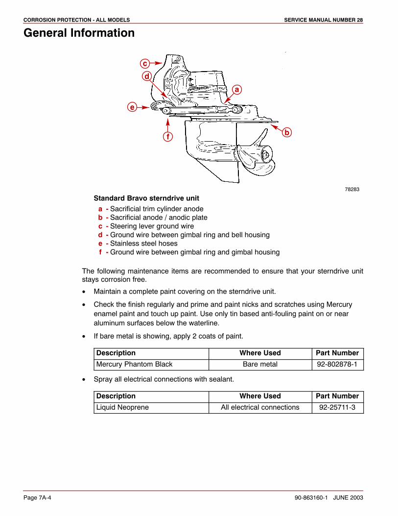
Standard Bravo sterndrive unita - Sacrificial trim cylinder anodeb - Sacrificial anode / anodic platec - Steering lever ground wired - Ground wire between gimbal ring and bell housinge - Stainless steel hosesf - Ground wire between gimbal ring and gimbal housing
The following maintenance items are recommended to ensure that your sterndrive unitstays corrosion free.
• Maintain a complete paint covering on the sterndrive unit.
• Check the finish regularly and prime and paint nicks and scratches using Mercuryenamel paint and touch up paint. Use only tin based anti-fouling paint on or nearaluminum surfaces below the waterline.
• If bare metal is showing, apply 2 coats of paint.
Description Where Used Part Number
Mercury Phantom Black Bare metal 92-802878-1
• Spray all electrical connections with sealant.
Description Where Used Part Number
Liquid Neoprene All electrical connections 92-25711-3
CORROSION PROTECTION - ALL MODELSSERVICE MANUAL NUMBER 28
90-863160-1 JUNE 2003 Page 7A-5
• Inspect the sacrificial trim tab at regular intervals and replace it before it is half gone.If a stainless steel prop is installed, additional anodes or a MerCathode System willbe required.
• Inspect the prop shaft for fishing line, which can cause corrosion on stainless steelshaft.
• Remove propeller at least every 60 days and lubricate the propeller shaft.
• Do not use lubricants containing graphite on or near aluminum in salt water.
• Do not paint trim tabs or the mounting surface.
Continuity Circuit
The transom assembly and sterndrive unit are equipped with ground circuit wires to ensuregood electrical continuity between engine, transom assembly, and sterndrive components.Good continuity is essential for the anode and MerCathode System to function mosteffectively.
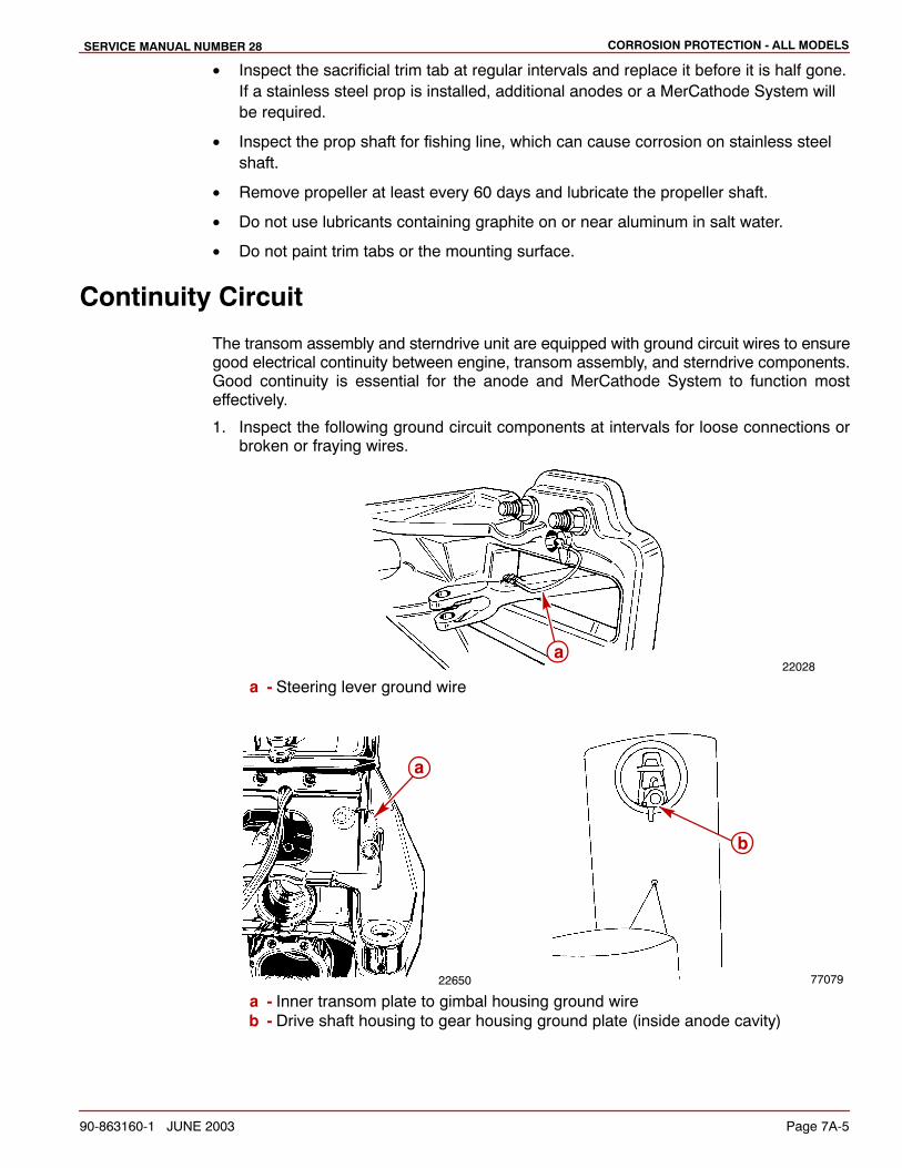
1. Inspect the following ground circuit components at intervals for loose connections orbroken or fraying wires.
22028a
a - Steering lever ground wire
22650 77079
a
b
a - Inner transom plate to gimbal housing ground wireb - Drive shaft housing to gear housing ground plate (inside anode cavity)
CORROSION PROTECTION - ALL MODELS SERVICE MANUAL NUMBER 28
Page 7A-6 90-863160-1 JUNE 2003
77100
a
b
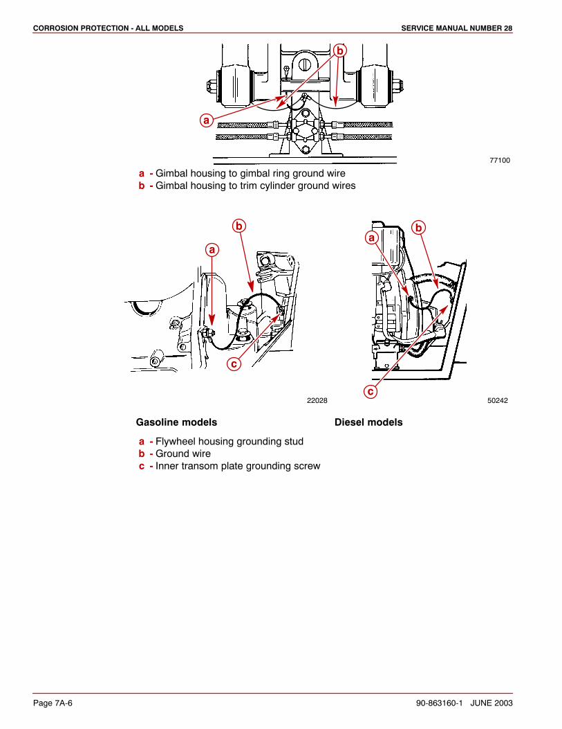
a - Gimbal housing to gimbal ring ground wireb - Gimbal housing to trim cylinder ground wires
22028 50242
a
b
c
ab
c
Gasoline models Diesel models
a - Flywheel housing grounding studb - Ground wirec - Inner transom plate grounding screw
CORROSION PROTECTION - ALL MODELSSERVICE MANUAL NUMBER 28
90-863160-1 JUNE 2003 Page 7A-7
22755 22031
b
a
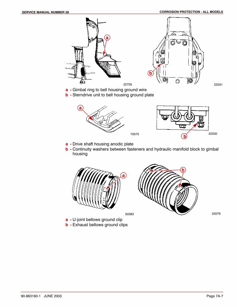
a - Gimbal ring to bell housing ground wireb - Sterndrive unit to bell housing ground plate
70575 22230
a
b
a - Drive shaft housing anodic plateb - Continuity washers between fasteners and hydraulic manifold block to gimbal
housing
50383 22079
ba
a - U-joint bellows ground clipb - Exhaust bellows ground clips
CORROSION PROTECTION - ALL MODELS SERVICE MANUAL NUMBER 28
Page 7A-8 90-863160-1 JUNE 2003
Trim Cylinder Anodes
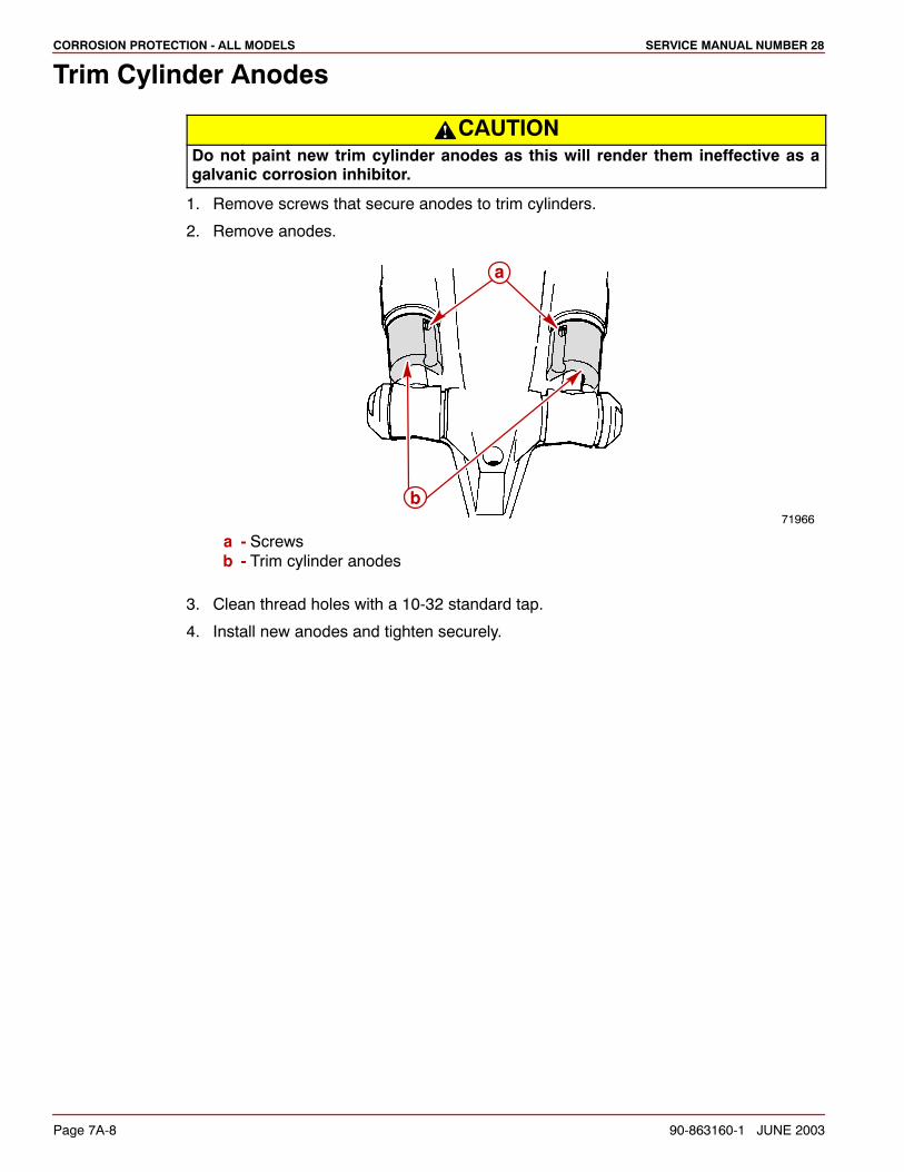
CAUTIONDo not paint new trim cylinder anodes as this will render them ineffective as agalvanic corrosion inhibitor.
1. Remove screws that secure anodes to trim cylinders.
2. Remove anodes.
71966
a
b
a - Screwsb - Trim cylinder anodes
3. Clean thread holes with a 10-32 standard tap.
4. Install new anodes and tighten securely.
CORROSION PROTECTION - ALL MODELSSERVICE MANUAL NUMBER 28
90-863160-1 JUNE 2003 Page 7A-9
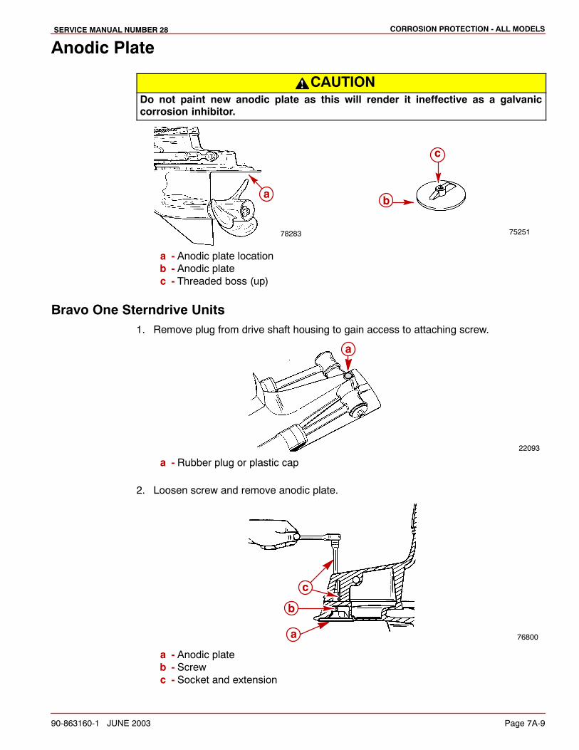
Anodic Plate
CAUTIONDo not paint new anodic plate as this will render it ineffective as a galvaniccorrosion inhibitor.
7525178283
b
c
a
a - Anodic plate locationb - Anodic platec - Threaded boss (up)
Bravo One Sterndrive Units1. Remove plug from drive shaft housing to gain access to attaching screw.
22093
a
a - Rubber plug or plastic cap
2. Loosen screw and remove anodic plate.
76800a
b
c
a - Anodic plateb - Screwc - Socket and extension
CORROSION PROTECTION - ALL MODELS SERVICE MANUAL NUMBER 28
Page 7A-10 90-863160-1 JUNE 2003
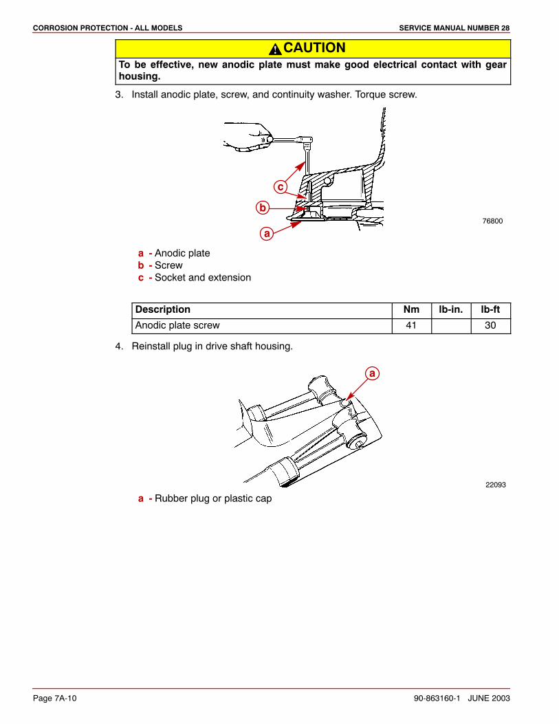
CAUTIONTo be effective, new anodic plate must make good electrical contact with gearhousing.
3. Install anodic plate, screw, and continuity washer. Torque screw.
76800
b
a
c
a - Anodic plateb - Screwc - Socket and extension
Description Nm lb-in. lb-ft
Anodic plate screw 41 30
4. Reinstall plug in drive shaft housing.
22093
a
a - Rubber plug or plastic cap
CORROSION PROTECTION - ALL MODELSSERVICE MANUAL NUMBER 28
90-863160-1 JUNE 2003 Page 7A-11
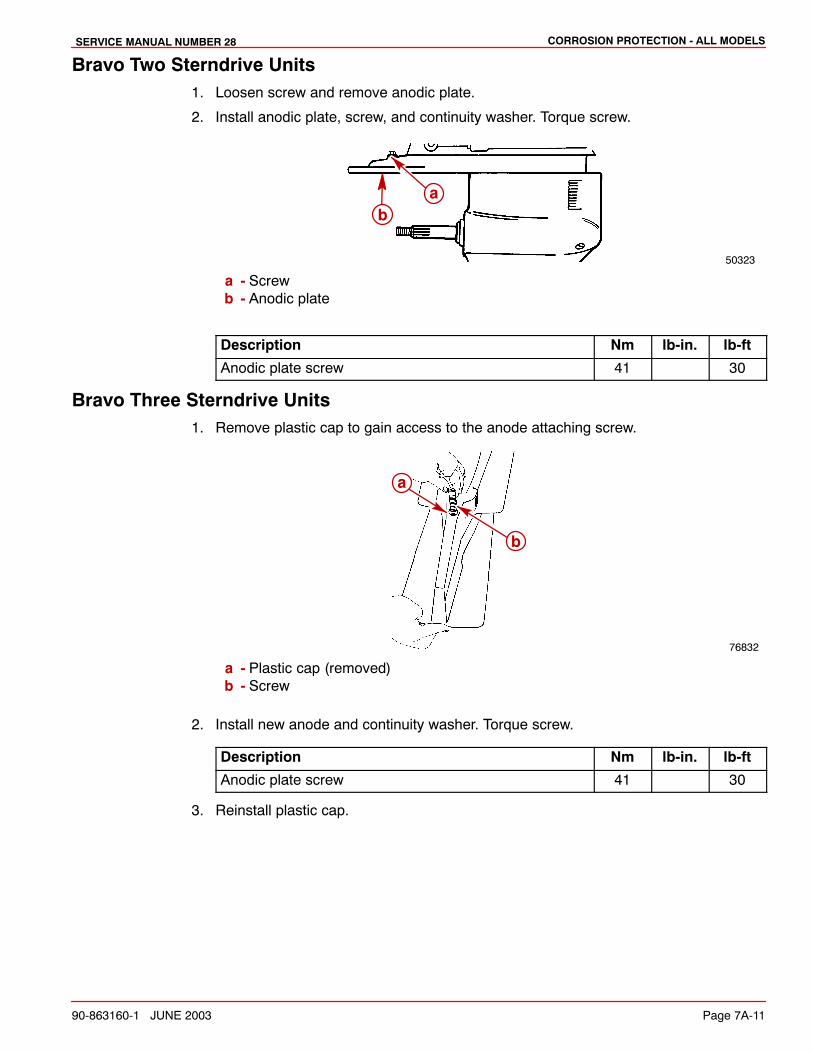
Bravo Two Sterndrive Units1. Loosen screw and remove anodic plate.
2. Install anodic plate, screw, and continuity washer. Torque screw.
50323
ba
a - Screwb - Anodic plate
Description Nm lb-in. lb-ft
Anodic plate screw 41 30
Bravo Three Sterndrive Units1. Remove plastic cap to gain access to the anode attaching screw.
76832
b
a
a - Plastic cap (removed)b - Screw
2. Install new anode and continuity washer. Torque screw.
Description Nm lb-in. lb-ft
Anodic plate screw 41 30
3. Reinstall plastic cap.
CORROSION PROTECTION - ALL MODELS SERVICE MANUAL NUMBER 28
Page 7A-12 90-863160-1 JUNE 2003
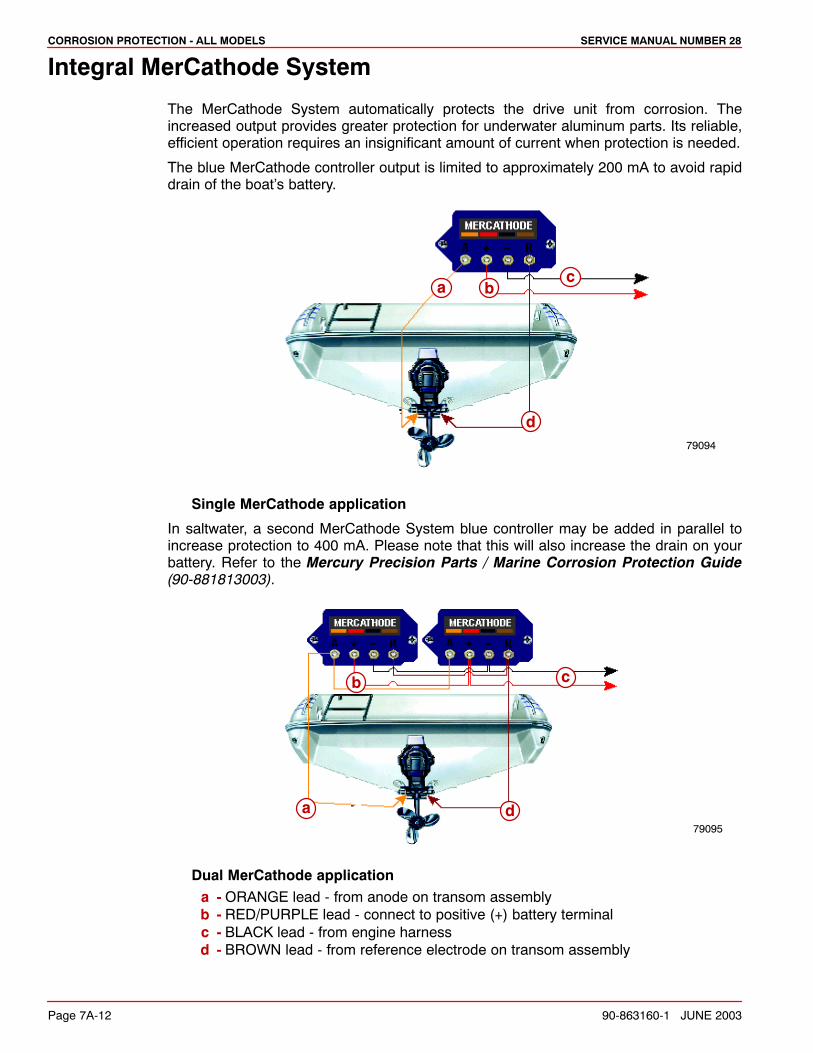
Integral MerCathode System
The MerCathode System automatically protects the drive unit from corrosion. Theincreased output provides greater protection for underwater aluminum parts. Its reliable,efficient operation requires an insignificant amount of current when protection is needed.
The blue MerCathode controller output is limited to approximately 200 mA to avoid rapiddrain of the boat’s battery.
bac
d79094
Single MerCathode application
In saltwater, a second MerCathode System blue controller may be added in parallel toincrease protection to 400 mA. Please note that this will also increase the drain on yourbattery. Refer to the Mercury Precision Parts / Marine Corrosion Protection Guide(90-881813003).
79095
a
b c
d
Dual MerCathode applicationa - ORANGE lead - from anode on transom assemblyb - RED/PURPLE lead - connect to positive (+) battery terminalc - BLACK lead - from engine harnessd - BROWN lead - from reference electrode on transom assembly
CORROSION PROTECTION - ALL MODELSSERVICE MANUAL NUMBER 28
90-863160-1 JUNE 2003 Page 7A-13
Removing Gimbal Mounted MerCathode AssemblyThe Hull Potential Test should be performed to ensure that the system is functioningproperly. Refer to Corrosion Protection Testing and Troubleshooting following in thissection.
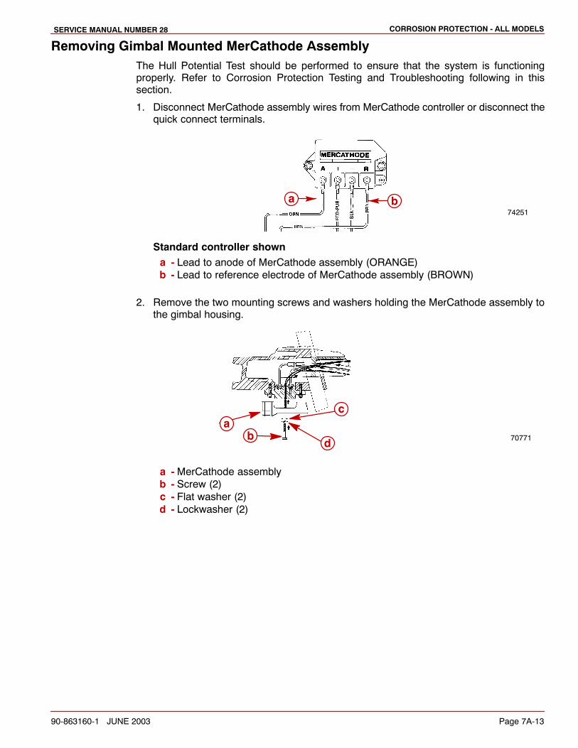
1. Disconnect MerCathode assembly wires from MerCathode controller or disconnect thequick connect terminals.
a b74251
Standard controller showna - Lead to anode of MerCathode assembly (ORANGE)b - Lead to reference electrode of MerCathode assembly (BROWN)
2. Remove the two mounting screws and washers holding the MerCathode assembly tothe gimbal housing.
70771
ab
c
d
a - MerCathode assemblyb - Screw (2)c - Flat washer (2)d - Lockwasher (2)
CORROSION PROTECTION - ALL MODELS SERVICE MANUAL NUMBER 28
Page 7A-14 90-863160-1 JUNE 2003
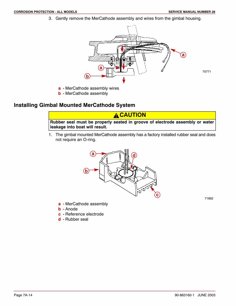
3. Gently remove the MerCathode assembly and wires from the gimbal housing.
70771a
b
a
a - MerCathode assembly wiresb - MerCathode assembly
Installing Gimbal Mounted MerCathode System
CAUTIONRubber seal must be properly seated in groove of electrode assembly or waterleakage into boat will result.
1. The gimbal mounted MerCathode assembly has a factory installed rubber seal and doesnot require an O-ring.
71862
b
a
c
d
a - MerCathode assemblyb - Anodec - Reference electroded - Rubber seal
CORROSION PROTECTION - ALL MODELSSERVICE MANUAL NUMBER 28
90-863160-1 JUNE 2003 Page 7A-15
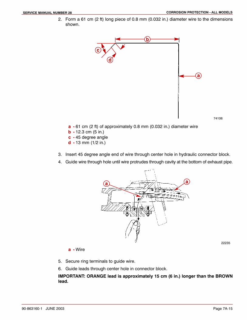
2. Form a 61 cm (2 ft) long piece of 0.8 mm (0.032 in.) diameter wire to the dimensionsshown.
74106
a
b
c
d
a - 61 cm (2 ft) of approximately 0.8 mm (0.032 in.) diameter wireb - 12.3 cm (5 in.)c - 45 degree angled - 13 mm (1/2 in.)
3. Insert 45 degree angle end of wire through center hole in hydraulic connector block.
4. Guide wire through hole until wire protrudes through cavity at the bottom of exhaust pipe.
22235
a a
a - Wire
5. Secure ring terminals to guide wire.
6. Guide leads through center hole in connector block.
IMPORTANT: ORANGE lead is approximately 15 cm (6 in.) longer than the BROWNlead.
CORROSION PROTECTION - ALL MODELS SERVICE MANUAL NUMBER 28
Page 7A-16 90-863160-1 JUNE 2003
7. Pull leads into the boat.
22234b
a
a - Guide wireb - Leads
CAUTIONDo not paint sacrificial anodes or MerCathode System anode/reference electrodeassembly, as this will render them ineffective as galvanic corrosion inhibitors.
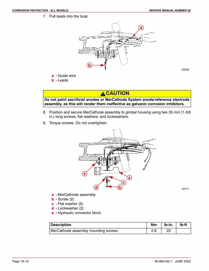
8. Position and secure MerCathode assembly to gimbal housing using two 35 mm (1-3/8in.) long screws, flat washers, and lockwashers.
9. Torque screws. Do not overtighten.
70771
a
bc
d
e
a - MerCathode assemblyb - Screw (2)c - Flat washer (2)d - Lockwasher (2)e - Hydraulic connector block
Description Nm lb-in. lb-ft
MerCathode assembly mounting screws 2.8 25
CORROSION PROTECTION - ALL MODELSSERVICE MANUAL NUMBER 28
90-863160-1 JUNE 2003 Page 7A-17
Connect to MerCathode Controller AssemblyNOTE: If BLACK (ground) wire is not available at terminal block or from wire harness, installa separate lead between controller negative (–) terminal and negative (–) battery cableattaching point on engine.
1. Securely connect electrical leads to MerCathode controller assembly. (See WiringDiagrams.)
2. Apply a thin coat of sealant to all electrical connections.
Description Where Used Part Number
Liquid Neoprene All electrical connections 92-25711-3
Wiring Diagrams
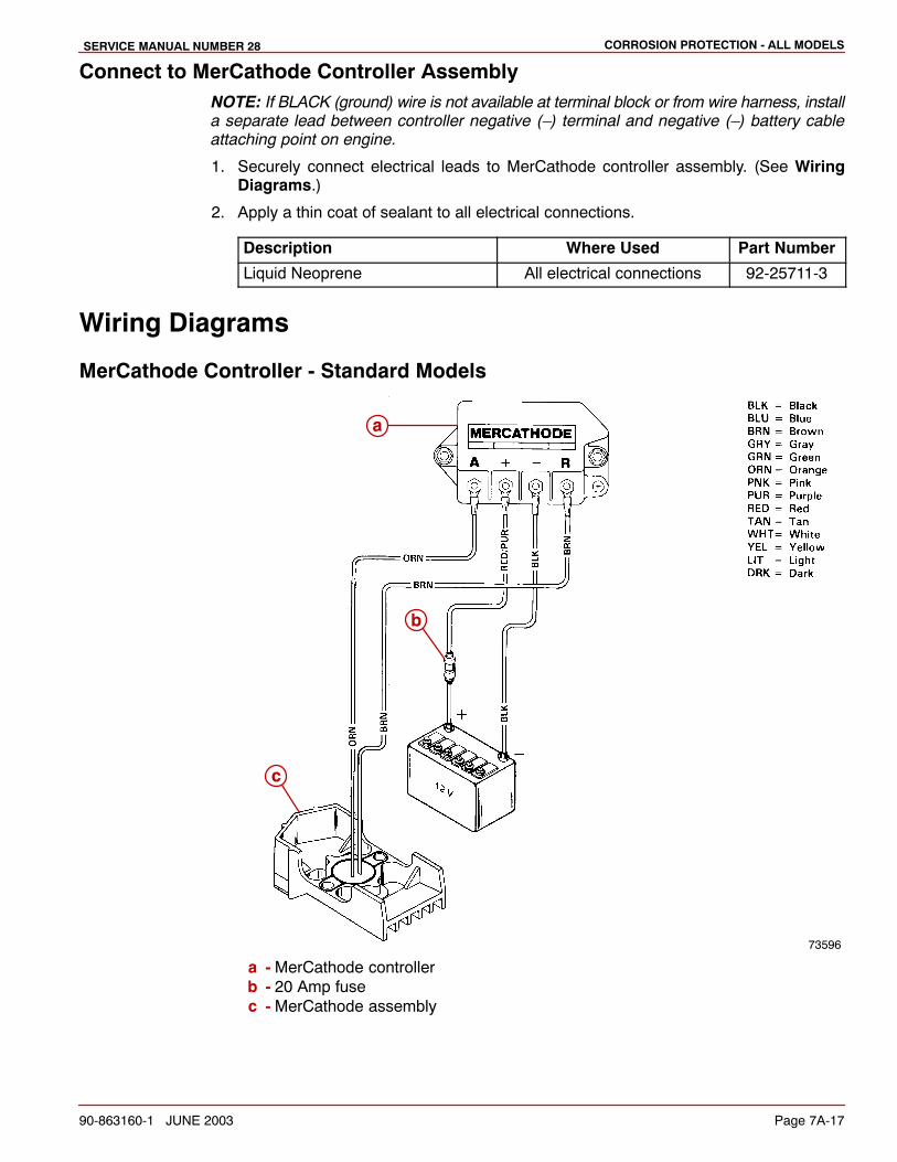
MerCathode Controller - Standard Models
73596
a
b
c
a - MerCathode controllerb - 20 Amp fusec - MerCathode assembly
CORROSION PROTECTION - ALL MODELS SERVICE MANUAL NUMBER 28
Page 7A-18 90-863160-1 JUNE 2003
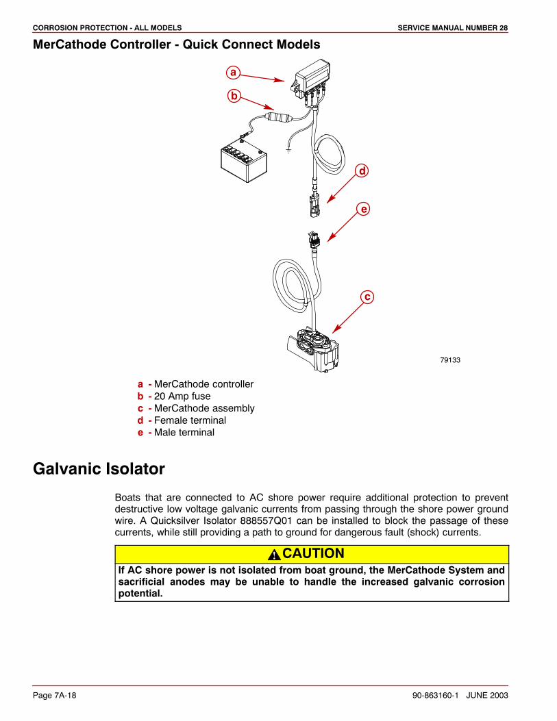
MerCathode Controller - Quick Connect Models
79133
c
b
a
e
d
a - MerCathode controllerb - 20 Amp fusec - MerCathode assemblyd - Female terminale - Male terminal
Galvanic Isolator
Boats that are connected to AC shore power require additional protection to preventdestructive low voltage galvanic currents from passing through the shore power groundwire. A Quicksilver Isolator 888557Q01 can be installed to block the passage of thesecurrents, while still providing a path to ground for dangerous fault (shock) currents.
CAUTIONIf AC shore power is not isolated from boat ground, the MerCathode System andsacrificial anodes may be unable to handle the increased galvanic corrosionpotential.
CORROSION PROTECTION - ALL MODELSSERVICE MANUAL NUMBER 28
90-863160-1 JUNE 2003 Page 7A-19
Corrosion Protection Testing and Troubleshooting
NOTE: The following corrosion protection test supersedes all previously issued tests. Thistest can be used on applications with or without a MerCathode System.
If the unit is equipped with a MerCathode System, this test should be performed annuallywhere the boat is moored to ensure that the system is functioning properly.
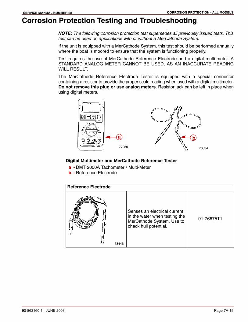
Test requires the use of MerCathode Reference Electrode and a digital multi-meter. ASTANDARD ANALOG METER CANNOT BE USED, AS AN INACCURATE READINGWILL RESULT.
The MerCathode Reference Electrode Tester is equipped with a special connectorcontaining a resistor to provide the proper scale reading when used with a digital multimeter.Do not remove this plug or use analog meters. Resistor jack can be left in place whenusing digital meters.
7683477959
a b
Digital Multimeter and MerCathode Reference Testera - DMT 2000A Tachometer / Multi-Meterb - Reference Electrode
Reference Electrode
73446
Senses an electrical currentin the water when testing theMerCathode System. Use tocheck hull potential.
91-76675T1
CORROSION PROTECTION - ALL MODELS SERVICE MANUAL NUMBER 28
Page 7A-20 90-863160-1 JUNE 2003
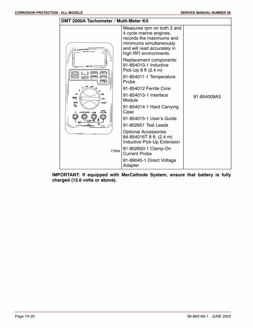
DMT 2000A Tachometer / Multi-Meter Kit
77959
Measures rpm on both 2 and4 cycle marine engines,records the maximums andminimums simultaneouslyand will read accurately inhigh RFI environments.
Replacement components:91-854010-1 InductivePick-Up 8 ft (2.4 m)
91-854011-1 TemperatureProbe
91-854012 Ferrite Core
91-854013-1 InterfaceModule
91-854014-1 Hard CarryingCase
91-854015-1 User’s Guide
91-802651 Test Leads
Optional Accessories:84-854016T 8 ft. (2.4 m)Inductive Pick-Up Extension
91-802650-1 Clamp-OnCurrent Probe
91-89045-1 Direct VoltageAdapter
91-854009A3
IMPORTANT: If equipped with MerCathode System, ensure that battery is fullycharged (12.6 volts or above).

CORROSION PROTECTION - ALL MODELSSERVICE MANUAL NUMBER 28
90-863160-1 JUNE 2003 Page 7A-21
IMPORTANT: Boats recently placed in service usually will produce a reading higherthan normal because the sterndrive unit is protected by a good finish and newsacrificial anodes. To obtain an accurate diagnosis, the test should be performedafter the boat has been in service at least one or two weeks. This will give the painta chance to soak and minor abrasions and scratches will have appeared resulting ina more accurate reading.
IMPORTANT: Boats should be moored, without being operated, for at least 8 hoursbefore performing tests. This is necessary to allow the MerCathode System and/orsacrificial anodes to polarize the surrounding water. Be careful not to rock the boatexcessively while boarding to perform a test as this will alter the test reading.
1. Set meter on scale required to read 0-2000 millivolts.
2. Connect the negative meter lead to the negative (–) battery terminal or other convenientengine ground.
3. Connect Reference Electrode Tester lead into positive (+) receptacle of meter.
4. Immerse Electrode Tester in the water within 15 cm (6 in.) of aft end of sterndrive unit.
IMPORTANT: There will be different voltage readings depending on the type ofMerCathode System you are testing.
5. The following readings indicate the corrosion protection status of the sterndrive unit.Refer to Section 1C - Troubleshooting.
Digital Multi-Meter Corrosion Protection
Freshwater
Between 750 - 1050
millivoltsSterndrive is protected
Below 750 millivolts Sterndrive is corroding
Above 1050 millivolts Sterndrive is overprotected
Digital Multi-Meter Corrosion Protection
Salt, Polluted, or MineralLaden Water
Between 850 - 1100
millivoltsSterndrive is protected
Laden WaterBelow 850 millivolts Sterndrive is corroding
Above 1100 millivolts Sterndrive is overprotected
CORROSION PROTECTION - ALL MODELS SERVICE MANUAL NUMBER 28
Page 7A-22 90-863160-1 JUNE 2003
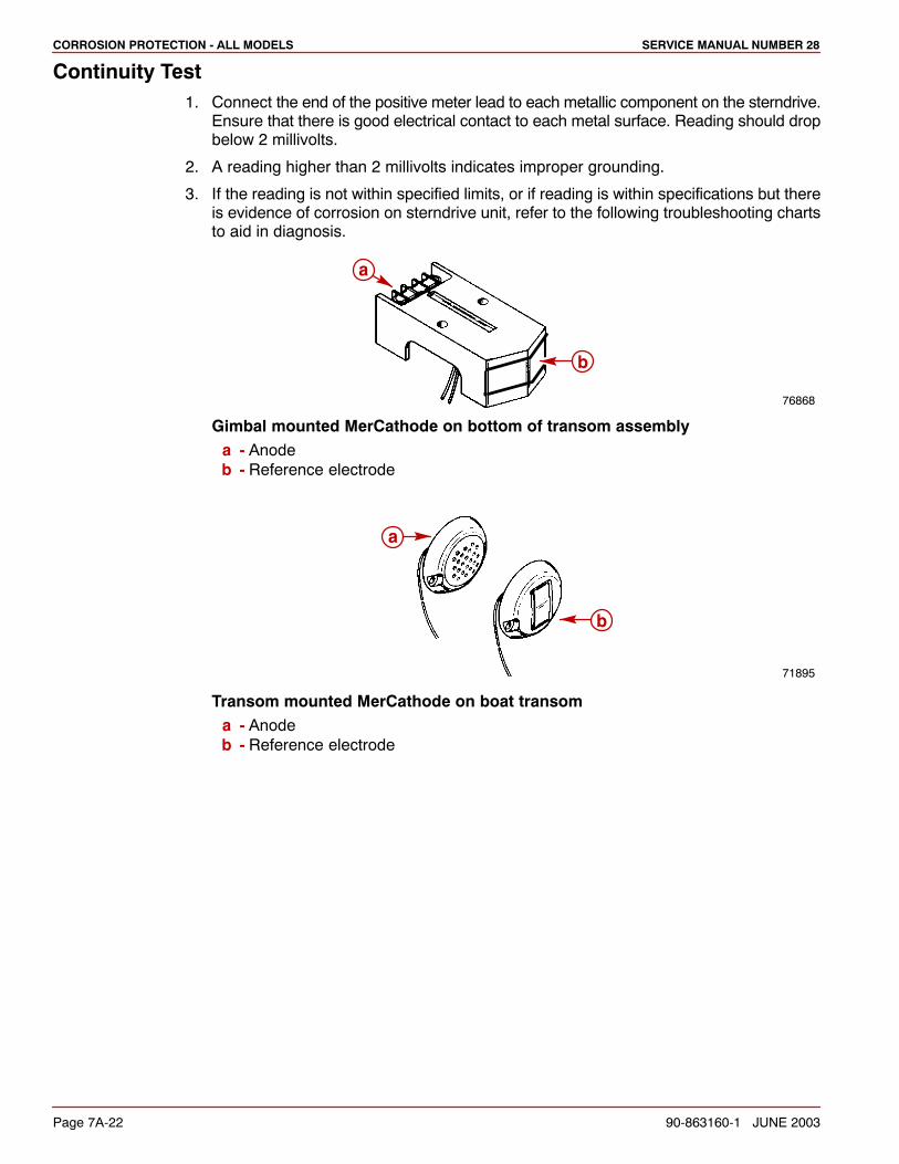
Continuity Test1. Connect the end of the positive meter lead to each metallic component on the sterndrive.
Ensure that there is good electrical contact to each metal surface. Reading should dropbelow 2 millivolts.
2. A reading higher than 2 millivolts indicates improper grounding.
3. If the reading is not within specified limits, or if reading is within specifications but thereis evidence of corrosion on sterndrive unit, refer to the following troubleshooting chartsto aid in diagnosis.
76868
a
b
Gimbal mounted MerCathode on bottom of transom assemblya - Anodeb - Reference electrode
71895
b
a
Transom mounted MerCathode on boat transoma - Anodeb - Reference electrode
CORROSION PROTECTION - ALL MODELSSERVICE MANUAL NUMBER 28
90-863160-1 JUNE 2003 Page 7A-23
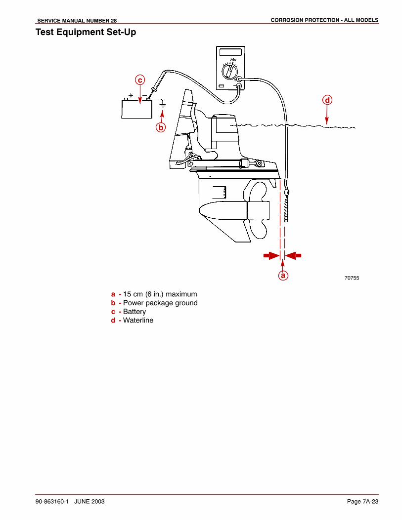
Test Equipment Set-Up
70755a
b
c
d
a - 15 cm (6 in.) maximumb - Power package groundc - Batteryd - Waterline
CORROSION PROTECTION - ALL MODELS SERVICE MANUAL NUMBER 28
Page 7A-24 90-863160-1 JUNE 2003
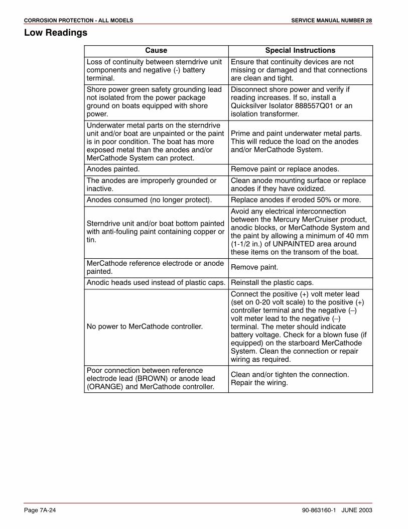
Low Readings
Cause Special Instructions
Loss of continuity between sterndrive unitcomponents and negative (-) batteryterminal.
Ensure that continuity devices are notmissing or damaged and that connectionsare clean and tight.
Shore power green safety grounding leadnot isolated from the power packageground on boats equipped with shorepower.
Disconnect shore power and verify ifreading increases. If so, install aQuicksilver Isolator 888557Q01 or anisolation transformer.
Underwater metal parts on the sterndriveunit and/or boat are unpainted or the paintis in poor condition. The boat has moreexposed metal than the anodes and/orMerCathode System can protect.
Prime and paint underwater metal parts.This will reduce the load on the anodesand/or MerCathode System.
Anodes painted. Remove paint or replace anodes.
The anodes are improperly grounded orinactive.
Clean anode mounting surface or replaceanodes if they have oxidized.
Anodes consumed (no longer protect). Replace anodes if eroded 50% or more.
Sterndrive unit and/or boat bottom paintedwith anti-fouling paint containing copper ortin.
Avoid any electrical interconnectionbetween the Mercury MerCruiser product,anodic blocks, or MerCathode System andthe paint by allowing a minimum of 40 mm(1-1/2 in.) of UNPAINTED area aroundthese items on the transom of the boat.
MerCathode reference electrode or anodepainted.
Remove paint.
Anodic heads used instead of plastic caps. Reinstall the plastic caps.
No power to MerCathode controller.
Connect the positive (+) volt meter lead(set on 0-20 volt scale) to the positive (+)controller terminal and the negative (–)volt meter lead to the negative (–)terminal. The meter should indicatebattery voltage. Check for a blown fuse (ifequipped) on the starboard MerCathodeSystem. Clean the connection or repairwiring as required.
Poor connection between referenceelectrode lead (BROWN) or anode lead(ORANGE) and MerCathode controller.
Clean and/or tighten the connection.Repair the wiring.
CORROSION PROTECTION - ALL MODELSSERVICE MANUAL NUMBER 28
90-863160-1 JUNE 2003 Page 7A-25
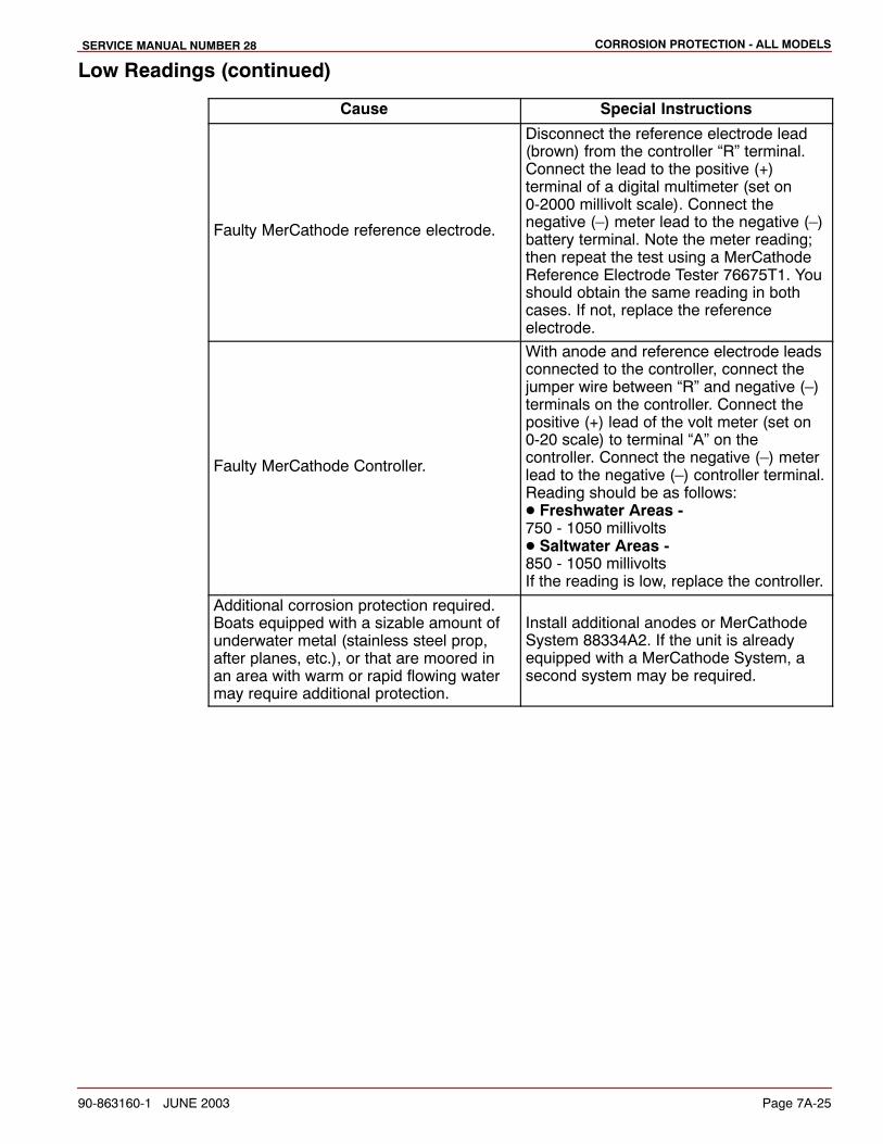
Low Readings (continued)
Cause Special Instructions
Faulty MerCathode reference electrode.
Disconnect the reference electrode lead(brown) from the controller “R” terminal.Connect the lead to the positive (+)terminal of a digital multimeter (set on0-2000 millivolt scale). Connect thenegative (–) meter lead to the negative (–)battery terminal. Note the meter reading;then repeat the test using a MerCathodeReference Electrode Tester 76675T1. Youshould obtain the same reading in bothcases. If not, replace the referenceelectrode.
Faulty MerCathode Controller.
With anode and reference electrode leadsconnected to the controller, connect thejumper wire between “R” and negative (–)terminals on the controller. Connect thepositive (+) lead of the volt meter (set on0-20 scale) to terminal “A” on thecontroller. Connect the negative (–) meterlead to the negative (–) controller terminal.Reading should be as follows:� Freshwater Areas - 750 - 1050 millivolts� Saltwater Areas - 850 - 1050 millivoltsIf the reading is low, replace the controller.
Additional corrosion protection required.Boats equipped with a sizable amount ofunderwater metal (stainless steel prop,after planes, etc.), or that are moored inan area with warm or rapid flowing watermay require additional protection.
Install additional anodes or MerCathodeSystem 88334A2. If the unit is alreadyequipped with a MerCathode System, asecond system may be required.
CORROSION PROTECTION - ALL MODELS SERVICE MANUAL NUMBER 28
Page 7A-26 90-863160-1 JUNE 2003
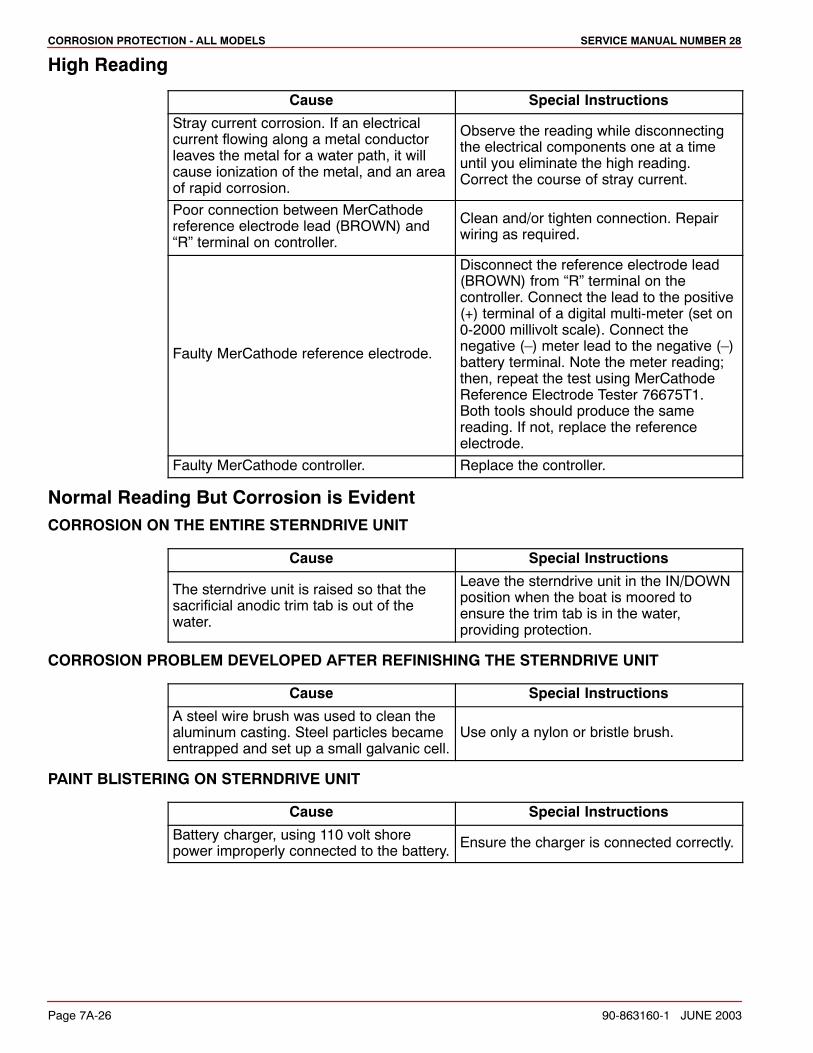
High Reading
Cause Special Instructions
Stray current corrosion. If an electricalcurrent flowing along a metal conductorleaves the metal for a water path, it willcause ionization of the metal, and an areaof rapid corrosion.
Observe the reading while disconnectingthe electrical components one at a timeuntil you eliminate the high reading.Correct the course of stray current.
Poor connection between MerCathodereference electrode lead (BROWN) and“R” terminal on controller.
Clean and/or tighten connection. Repairwiring as required.
Faulty MerCathode reference electrode.
Disconnect the reference electrode lead(BROWN) from “R” terminal on thecontroller. Connect the lead to the positive(+) terminal of a digital multi-meter (set on0-2000 millivolt scale). Connect thenegative (–) meter lead to the negative (–)battery terminal. Note the meter reading;then, repeat the test using MerCathodeReference Electrode Tester 76675T1.Both tools should produce the samereading. If not, replace the referenceelectrode.
Faulty MerCathode controller. Replace the controller.
Normal Reading But Corrosion is EvidentCORROSION ON THE ENTIRE STERNDRIVE UNIT
Cause Special Instructions
The sterndrive unit is raised so that thesacrificial anodic trim tab is out of thewater.
Leave the sterndrive unit in the IN/DOWNposition when the boat is moored toensure the trim tab is in the water,providing protection.
CORROSION PROBLEM DEVELOPED AFTER REFINISHING THE STERNDRIVE UNIT
Cause Special Instructions
A steel wire brush was used to clean thealuminum casting. Steel particles becameentrapped and set up a small galvanic cell.
Use only a nylon or bristle brush.
PAINT BLISTERING ON STERNDRIVE UNIT
Cause Special Instructions
Battery charger, using 110 volt shorepower improperly connected to the battery.
Ensure the charger is connected correctly.
CORROSION PROTECTION - ALL MODELSSERVICE MANUAL NUMBER 28
90-863160-1 JUNE 2003 Page 7A-27
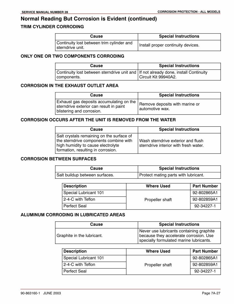
Normal Reading But Corrosion is Evident (continued)TRIM CYLINDER CORRODING
Cause Special Instructions
Continuity lost between trim cylinder andsterndrive unit.
Install proper continuity devices.
ONLY ONE OR TWO COMPONENTS CORRODING
Cause Special Instructions
Continuity lost between sterndrive unit andcomponents.
If not already done, install ContinuityCircuit Kit 99940A2.
CORROSION IN THE EXHAUST OUTLET AREA
Cause Special Instructions
Exhaust gas deposits accumulating on thesterndrive exterior can result in paintblistering and corrosion.
Remove deposits with marine orautomotive wax.
CORROSION OCCURS AFTER THE UNIT IS REMOVED FROM THE WATER
Cause Special Instructions
Salt crystals remaining on the surface ofthe sterndrive components combine withhigh humidity to cause electrolyteformation, resulting in corrosion.
Wash sterndrive exterior and flushsterndrive interior with fresh water.
CORROSION BETWEEN SURFACES
Cause Special Instructions
Salt buildup between surfaces. Protect mating parts with lubricant.
Description Where Used Part Number
Special Lubricant 101 92-802865A1
2-4-C with Teflon Propeller shaft 92-802859A1
Perfect Seal
p
92-34227-1
ALUMINUM CORRODING IN LUBRICATED AREAS
Cause Special Instructions
Graphite in the lubricant.Never use lubricants containing graphitebecause they accelerate corrosion. Usespecially formulated marine lubricants.
Description Where Used Part Number
Special Lubricant 101 92-802865A1
2-4-C with Teflon Propeller shaft 92-802859A1
Perfect Seal
p
92-34227-1
CORROSION PROTECTION - ALL MODELS SERVICE MANUAL NUMBER 28
Page 7A-28 90-863160-1 JUNE 2003
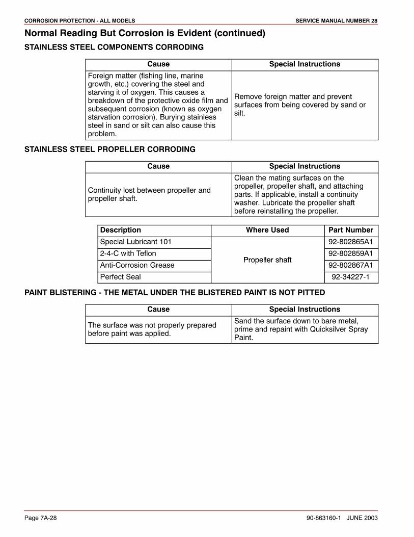
Normal Reading But Corrosion is Evident (continued)STAINLESS STEEL COMPONENTS CORRODING
Cause Special Instructions
Foreign matter (fishing line, marinegrowth, etc.) covering the steel andstarving it of oxygen. This causes abreakdown of the protective oxide film andsubsequent corrosion (known as oxygenstarvation corrosion). Burying stainlesssteel in sand or silt can also cause thisproblem.
Remove foreign matter and preventsurfaces from being covered by sand orsilt.
STAINLESS STEEL PROPELLER CORRODING
Cause Special Instructions
Continuity lost between propeller andpropeller shaft.
Clean the mating surfaces on thepropeller, propeller shaft, and attachingparts. If applicable, install a continuitywasher. Lubricate the propeller shaftbefore reinstalling the propeller.
Description Where Used Part Number
Special Lubricant 101 92-802865A1
2-4-C with TeflonPropeller shaft
92-802859A1
Anti-Corrosion GreasePropeller shaft
92-802867A1
Perfect Seal 92-34227-1
PAINT BLISTERING - THE METAL UNDER THE BLISTERED PAINT IS NOT PITTED
Cause Special Instructions
The surface was not properly preparedbefore paint was applied.
Sand the surface down to bare metal,prime and repaint with Quicksilver SprayPaint.


![Bellows Instructions[1]](https://img.pdfslide.net/doc/110x75/577d33b81a28ab3a6b8b8b19/bellows-instructions1.jpg)


