Embed Size (px)
Citation preview
SECTION C -INFRASTRUCTURE & OPERATION
Attachment C1: Operational Information Requirements
- Outline Description of the Treatment Process at Kildalkey WWTP & Agglomeration
- Drawing No. 5270-2888
- Drawing No. 5270-2889
For
insp
ectio
n pur
pose
s only
.
Conse
nt of
copy
right
owne
r req
uired
for a
ny ot
her u
se.
EPA Export 26-07-2013:14:15:38
)
)
OUTLINE DESCRIPTION OF THE TREATMENT PROCESS FOR KILDALKEY WASTE
WATER TREATMENT PLANT AND AGGLOMERATION
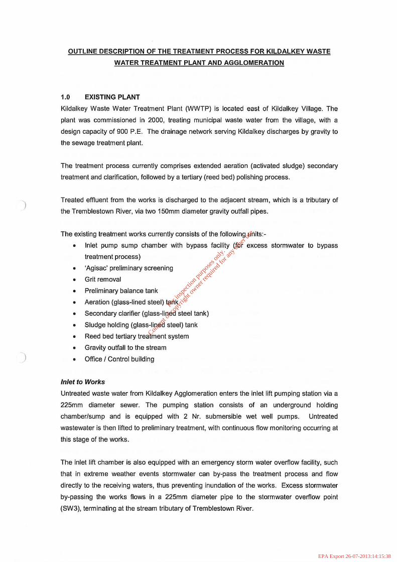
1.0 EXISTING PLANT
Kildalkey Waste Water Treatment Plant (WWTP) is located east of Kildalkey Village. The
plant was commissioned in 2000, treating municipal waste water from the village, with a
design capacity of 900 P.E. The drainage network serving Kildalkey discharges by gravity to
the sewage treatment plant.
The treatment process currently comprises extended aeration (activated sludge) secondary
treatment and clarification, followed by a tertiary (reed bed) polishing process.
Treated effluent from the works is discharged to the adjacent stream, which is a tributary of
the Tremblestown River, via two 150mm diameter gravity outfall pipes.
The existing treatment works currently consists of the following units:-
• Inlet pump sump chamber with bypass facility (for excess stormwater to bypass
treatment process)
• 'Agisac' preliminary screening
• Grit removal
• Preliminary balance tank
• Aeration (glass-lined steel) tank
• Secondary clarifier (glass-lined steel tank)
• Sludge holding (glass-lined steel) tank
• Reed bed tertiary treatment system
• Gravity outfall to the stream
• Offlce / Control building
Inlet to Works
Untreated waste water from Kildalkey Agglomeration enters the inlet lift pumping station via a
225mm diameter sewer. The pumping station consists of an underground holding
chamber/sump and is equipped with 2 Nr. submersible wet well pumps. Untreated
wastewater is then lifted to preliminary treatment, with continuous flow monitoring occurring at
Ihis stage of the works.
The inlet lift chamber is also equipped with an emergency storm water overfiow facility, such
that in extreme weather events stormwater can by-pass the treatment process and fiow
directly to the receiving waters, thus preventing inundation of the works. Excess stormwater
by-passing the works flows in a 225mm diameter pipe to the stormwater overfiow point
(SW3), terminating at the stream tributary of Tremblestown River.
For
insp
ectio
n pur
pose
s only
.
Conse
nt of
copy
right
owne
r req
uired
for a
ny ot
her u
se.
EPA Export 26-07-2013:14:15:38
Inlet Works (Preliminary Treatment)
Preliminary treatment entails the removal of plastics, rags, grit, silt and sand from the waste
stream. Screening facilities are provided for solids removal of inorganic materials via an
'Agisac' fine screen. This screen is designed to produce washed screenings down to a
particle size of 3mm, with delivery to a nearby skip. Grit removal of the incoming screened
sewage is provided via a grit trap I classifier. The collected grit is also discharged to the
adjacent skip.
Screened sewage flows forward to an underground balance tank (capacity 32m' approx.).
The balance tank ensures that homogenous sewage is fed to the process plant. Following a
short retention time in the balance tank, partially treated waste water is then pumped (via two
submersible forward feed pumps) in a 100mm diameter rising main to the aeration unit.
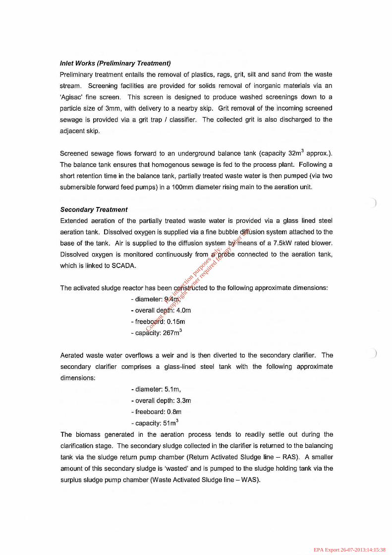
Secondary Treatment
Extended aeration of the partially treated waste water is provided via a glass lined steel
aeration tank. Dissolved oxygen is supplied via a fine bubble diffusion system attached to the
base of the tank. Air is supplied to the diffusion system by means of a 7.5kW rated blower.
Dissolved oxygen is monitored continuously from a probe connected to the aeration tank,
which is linked to SCADA.
The activated sludge reactor has been constructed to the following approximate dimensions:
- diameter: gAm,
- overall depth: 4.0m
- freeboard: O.15m
- capacity: 267m'
Aerated waste water overflows a weir and is then diverted to the secondary clarifier. The
secondary clarifier comprises a glass-lined steel tank with the following approximate
dimensions:
- diameter: 5.1m,
- overall depth: 3.3m
- freeboard: O.8m
- capacity: 51 m'
The biomass generated in the aeration process tends to readily settle out during the
clarification stage. The secondary sludge collected in the clarifier is returned to the balancing
tank via the sludge return pump chamber (Return Activated Sludge line - RAS). A smaller
amount of this secondary sludge is 'wasted' and is pumped to the sludge holding tank via the
surplus sludge pump chamber (Waste Activated Sludge line - WAS).
)
)
For
insp
ectio
n pur
pose
s only
.
Conse
nt of
copy
right
owne
r req
uired
for a
ny ot
her u
se.
EPA Export 26-07-2013:14:15:38

)
)
Currently a split-flow operation is in place at the plant, whereby treated effluent discharge, on
exiting the clarification stage, is split, with a proportion of this treated effluent discharging
directly to the receiving waters (refer to Secondary Discharge Point SW2) and the remainder
flowing forward to receive tertiary treatment in the on-site reed bed system.
Tertiary Treatment and Treated Effluent Outfall
As stated above, a portion of treated effluent also receives tertiary treatment. Effluent exiting
the secondary clarifier flows by gravity in a 150mm diameter pipe to the tertiary treatment
chambers, where it is distributed to the reed beds.
The effluent is distributed through the substrate layers of reed beds (6 nr. reed bed units on
site). The overflow from the reed beds is collected in an outflow chamber and then
discharged by gravity in 150mm diameter pipe to the adjacent stream (primary discharge
point SW1). Discharge of treated effluent is through a simple open-ended pipeline,
terminating directly over the stream, above the water level.
Sludge Handling
Settled sludge is drawn from the clarifier base via the surplus sludge pump chamber and sent
forward for temporary storage in the (glass-lined steel) sludge holding tank. As discussed
above, return activated sludge (RAS) is pumped back to the balancing tank via the sludge
return pump chamber. Waste sludge is pumped to the sludge holding tank at a rate, which is
determined by the MLSS concentration in the aeration unit. The sludge holding tank has a
capacity of approximately 34m3.
Sludge is allowed to settle in this tank and the resulting supernatant is siphoned back to the
balance tank. The sludge holding tank is emptied monthly (approximately) by tanker with the
thickened sludge being transported to the Navan Waste Water Treatment Plant for
dewatering.
For
insp
ectio
n pur
pose
s only
.
Conse
nt of
copy
right
owne
r req
uired
for a
ny ot
her u
se.
EPA Export 26-07-2013:14:15:38
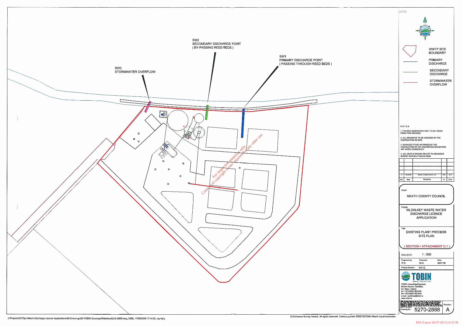
SW3 STORMWATER OVERFLOW
)
J:IProjecls\5270pp Meath Discharge Licence ApplicalionsID6-Drawings\02·TOBIN DrawingsIKHdalkey\5270·2888.dwg, 2888, 1710612009 17:14:22. ray kelly
SW2 SECONDARY DISCHARGE POINT (BY-PASSING REED BEDS)
SW1 PRIMARY DISCHARGE POINT ( PASSING THROUGH REED BEDS)
o Ordnance Survey Ireland. All rights reserved. Licence number 2008/10CeMA' Meath Local Authorities
Q
NOTES
WWTPSITE BOUNDARY
PRIMARY DISCHARGE
SECONDARY DISCHARGE
STORMWATER OVERFLOW
I . FIGURED DIMENSIONS ONLY TO BE TAKEN FROM nilS DRAWING
2. ALL DRAWINGS TO BE CHECKEO BY THE CONTRACTOR ON SITE
3. ENGINEER TO BE INFORMED BY THE CONTRACTOR OF ANY DISCREPANCIES BEFORE ANY WORK COMMENCES
4. ALL LEVELS SHOWN RELATE TO ORDNANCE SURVEY DATUM AT MALIN HEAD
CIi""t:
MEATH COUNTY COUNCIL
Pro)ed.: KILDALKEY WASTE WATER
DISCHARGE LICENCE APPLICATION
TiIlu:
EXISTING PLANT PROCESS SITE PLAN
SECTION I ATTACHMENT C.1
Sc;Jlu@ A3. 1: 500
Prepared by: Checked:
R.K. M.H.
e TOBIN P.~d J To",o & Co ~ kJ
TOBIN Consulting EnginooB. Murk!!1 SqU'"!!, Castlcbor. Co. Mayo. 1"""00. lei: +35J..(0){;4·0021401 fax :+35J..(O)fl.4·0021534 ... mail: Qlsllebar@tobjnie WWW.lobin.ie
OBI!!:
MAY09
A
For
insp
ectio
n pur
pose
s only
.
Conse
nt of
copy
right
owne
r req
uired
for a
ny ot
her u
se.
EPA Export 26-07-2013:14:15:38
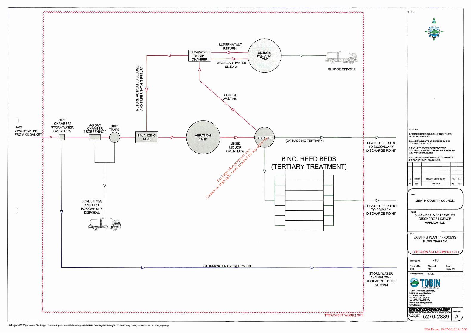
INLET
CHAMBER! AGISAC GRIT RAW STORMWATER CHAMBER TRAPS WASTEWATER OVERFLOW (SCREENING) FROM KILDALKEY L ___ ~{~j
=':::":"~-1L...r
SCREENINGS AND GRIT
) FOR OFF-SITE DISPOSAL
Wz "'0: o=> =>1-...JW fflo: 01-wz 1-« ~~ ;::z uo: «W z"o:=> =>ffl 1-0 wz 0:«
)----1 BALANCING TANK
~
RASNIAS SUMP
CHAMBER
SUPERNATANT RETURN
WASTE A; TIVATED SLUDGE
SLUDGE WASTING
SLUDGE HOLDING
TANK
SLUDGE OFF-SITE
AERATION TANK
f---i>-----j CLARIFIER f----------C>--------+ ----1i>----
MIXED LIQUOR
OVERFLOW
STORMWATER OVERFLOW LINE
(BY-PASSING TERTIARY)
6 NO_ REED BEDS (TERTIARY TREATMENT) ,--- f--
f-- I--
I-- I---
f-- f--
f-- f--
~ f--
TREATMENT WORKS SITE
TREATED EFFLUENT TO SECONDARY
DISCHARGE POINT
~
TREATED EFFLUENT TO PRIMARY
DISCHARGE POINT
STORM WATER OVERFLOW
DISCHARGE TO THE STREAM
NOTES
1. FIGUREO DIMENSIONS ON\. Y TO BE TAKEN fROM THIS DRAWlNG
2 . ALL DRAWINGS TO BE CHECKED BY mE CONTRACTOR ON SITE
3. ENGINEER TO BE INFORMED BY THE CONTRACTOR OF ANY DISCREPANCIES BEFORE ANY WORK COMMENCES
.. . ALL lEVELS SHOWN RELATE TO ORDNANCE SURVEY DATUM AT M"LlN HEAD
,,,., I ~ ."
1"- ~.
MEATH COUNTY COUNCIL
Pru)ed: KILDALKEY WASTE WATER
DISCHARGE LICENCE APPLICATION
,.." EXISTING PLANT I PROCESS
FLOW DIAGRAM
'--( SECTION I ATIACHMENT C.l LI
Chl!clu""
M,H.
M.F.G.
9 TOBIN p . . ... J 1 0""' & Co I t.1
TOBIN CO"liuUlng Englnccnl, MllrloDl Sqw,n, Ca:ltlebar. Co. Mo)'O. I"""rd. 101: .353-(0)904·0021401 fo.:.l5J.j0JII-t·00215:>4 o-mall; ",,"lIelxllfi'\cbin.ir! ...-.Iobin.1e
Ollie:
MAY 09
l::~~'~;~~;;;' "p," L-____________________________________________________________________________________________________________________________ ~, /
J:\Projects\s270pp Meath Discharge Ucef'l(;e Applicalions\OS·Drawings\()2-TOBIN Orawings\Kilttalkoy\s270·2B89.dwg, 2889. 1710612009 17:14:50, ray kelly
For
insp
ectio
n pur
pose
s only
.
Conse
nt of
copy
right
owne
r req
uired
for a
ny ot
her u
se.
EPA Export 26-07-2013:14:15:38
SECTION C -INFRASTRUCTURE & OPERATION
Attachment C2: Outfall Construction & Design
- Outline Description of Outfall Design and Construction
- Drawing No. 5270-2892
- Drawing No. 5270-2893
For
insp
ectio
n pur
pose
s only
.
Conse
nt of
copy
right
owne
r req
uired
for a
ny ot
her u
se.
EPA Export 26-07-2013:14:15:38
)
)
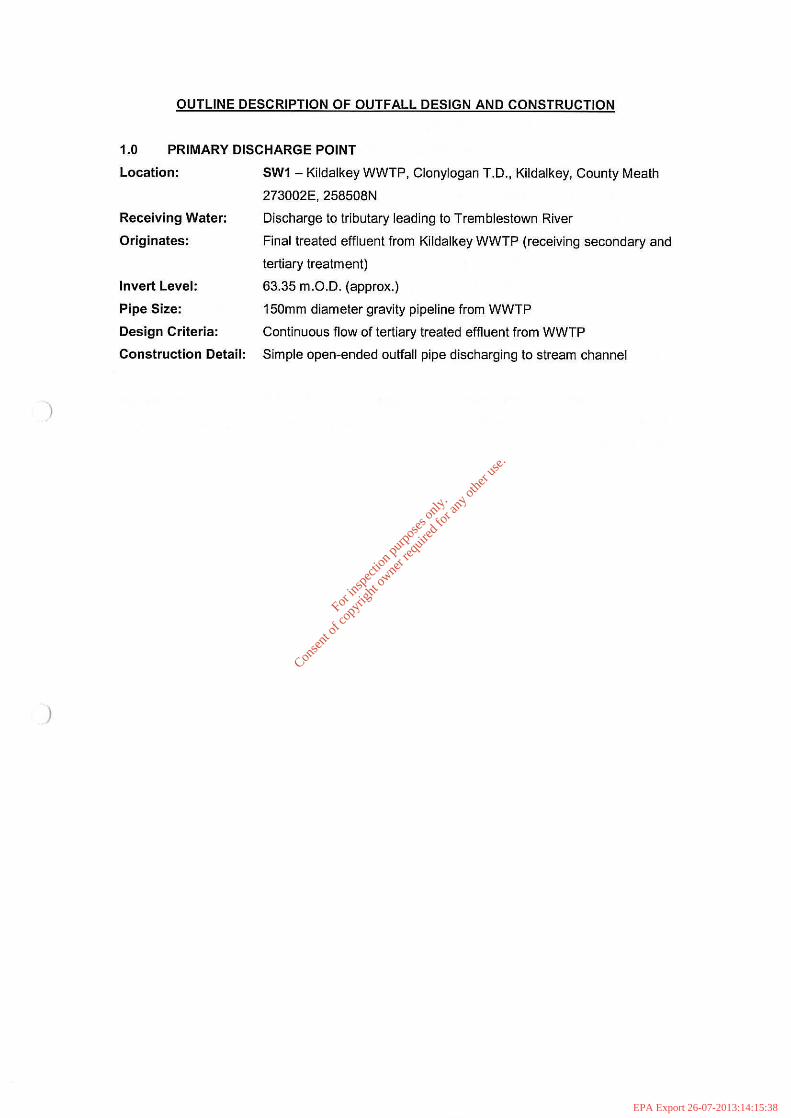
OUTLINE DESCRIPTION OF OUTFALL DESIGN AND CONSTRUCTION
1.0 PRIMARY DISCHARGE POINT
Location: SW1 - Kildalkey WWTP, Clonylogan TD., Kildalkey, County Meath
273002E, 258508N
Receiving Water: Discharge to tributary leading to Tremblestown River
Originates: Final treated effluent from Kildalkey WWTP (receiving secondary and
tertiary treatment)
Invert Level: 63.35 m.OD. (approx.)
Pipe Size: 150mm diameter gravity pipeline from WWTP
Design Criteria: Continuous flow of tertiary treated effluent from WWTP
Construction Detail: Simple open-ended outfall pipe discharging to stream channel
For
insp
ectio
n pur
pose
s only
.
Conse
nt of
copy
right
owne
r req
uired
for a
ny ot
her u
se.
EPA Export 26-07-2013:14:15:38
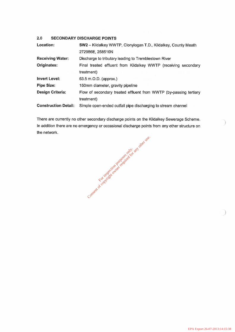
2.0 SECONDARY DISCHARGE POINTS
Location:
Receiving Water:
Originates:
Invert Level:
Pipe Size:
Design Criteria:
SW2 - Kildalkey WWTP, Clonylogan TD., Kildalkey, Counly Mealh
272986E, 258510N
Discharge to tributary leading to Tremblestown River
Final treated effluent from Kildalkey WWTP (receiving secondary
treatment)
63.5 m.OD. (approx.)
150mm diameter, gravity pipeline
Flow of secondary treated effluent from WWTP (by-passing tertiary
treatment)
Construction Detail: Simple open-ended outfall pipe discharging to stream channel
There are currently no other secondary discharge points on the Kildalkey Sewerage Scheme.
In addition there are no emergency or occasional discharge points from any other structure on
the network.
For
insp
ectio
n pur
pose
s only
.
Conse
nt of
copy
right
owne
r req
uired
for a
ny ot
her u
se.
EPA Export 26-07-2013:14:15:38

)
3.0 STORM WATER OVERFLOW DISCHARGE POINTS
Location:
Receiving Water:
Originates:
Invert Level:
Pipe Size:
Design Criteria:
SW3 - Kildalkey WWTP, Clonylogan T.D., Kildalkey, County Meath
272960E,258512N
Discharge to tributary leading to Tremblestown River
Storm water overflow from inlet pumping station sump at Kildalkey
WWTP
63.5 m.O.D. (approx.)
225mm diameter gravity pipeline
The inlet lift chamber is equipped with an emergency storm water
overflow facility, such that in extreme weather events stormwater can
by-pass the treatment process and fiow directly to the receiving
waters, thus preventing inundation and wash out of the works.
Excess stormwater by-passing the works fiows in a 225mm diameter
pipe to the stormwater overflow point (SW3), terminating at the
stream tributary of Tremblestown River.
Construction Detail: Simple open-ended outfall pipe discharging to stream channel
For
insp
ectio
n pur
pose
s only
.
Conse
nt of
copy
right
owne
r req
uired
for a
ny ot
her u
se.
EPA Export 26-07-2013:14:15:38

/ SW2 SECONDARY DISCHARGE POINT
~~ E I L
) o
CLONYLOGAN
)
MOYRATH
[]
NOTE S
WWTPSITE BOUNDARY
PRIMARY DISCHARGE
SECONDARY DISCHARGE
STORMWATER OVERFLOW
I . FIGURED DIMENSIONS ONLY TO BE T.-.KEN FRO~1lliIS ORAWING
2. ALL DRAWINGS TO BE CHECKED BY TliE CONTRACTOR ON SITE
J , ENGINEER TO BE INFORMED BY THE CONTRACTOR OF ANY DISCREPANCIES BEFORE ANY WORK COMMENCES
4. ALL lEVELS SHOWN RELATE TO ORDNANCE SURVEY DATUM AT MALIN HEAD
'nUI010 ""AII'=CII
e_ ".
C~"nt
MEATH COUNTY COUNCIL
Plt!lea KILDALKEY WASTE WATER
DISCHARGE LICENCE APPLICATION
T~Ie:
PRIMARY DISCHARGE POINT, SECONDARY DISCHARGE POINT &
STORMWATER OVERFLOW LAYOUT I LOCATION PLAN
(SECTION I ATTACHMENT C.2 )
SGIIle @AJ. 1 : 5000
P f~redby: Che!: koo:
R.K. M.H.
projKt OlrflCtOr: M.F.G.
9 TOBIN r .. otI; J I cbi'l & o, t tl
TOBIN CGnsulll1l!l Eng;neers, Market Square, COsUellllr, Co. Mayo, Ireland. leI; .353-(O)04 · G02I~OI
IWI.:< J5J.(O)04 ·gQ215 304 IHnlllt [email protected] ~.tobinlo
Oat,,: MAY 09
--=:...::=.-=~~ 5-.:=:":\:'.c:r-:...-:::::.,:--::" RlI'rision:
':::::=========:--:-=--:--:::-:--_____ ....:1...-_ ___ ...::::::::~ __ L_~ ___ .....J.±j+~~::____=_::_:_:_,_l,=-__:__:::==-__:_:_:_--,,----J _.,N, 5270-2892 A J:\Projacts\S270pp Meath Discharge Licence Applicalions\06-Drawings\02.TOBIN Orawings\Kildalkey\5270.2BSO,2BS1, 2884,2886,2892,2895.dwg, 2892, 17/0612009 17:09:56, ray keRy ICI Ordnance Survey Ireland. All rights reserved. Licence nymber 2008/10CCMN Meath Lccal Authorities
For
insp
ectio
n pur
pose
s only
.
Conse
nt of
copy
right
owne
r req
uired
for a
ny ot
her u
se.
EPA Export 26-07-2013:14:15:38
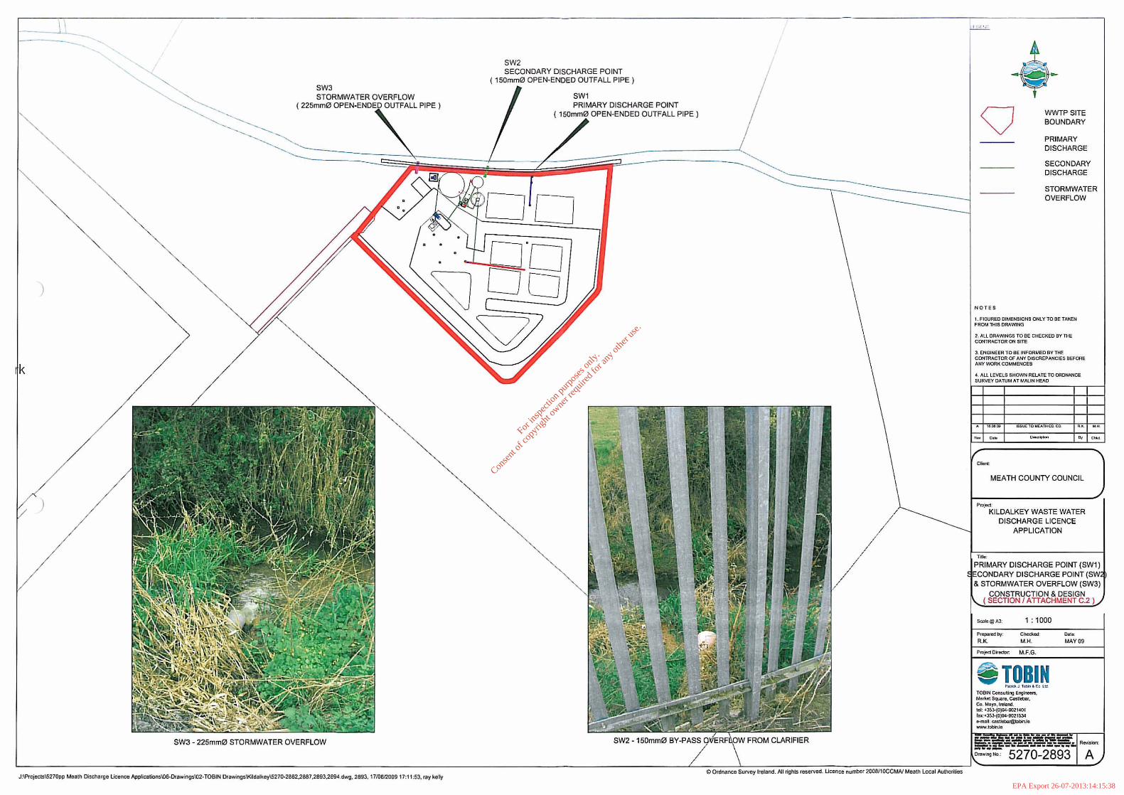
SW3 STORMWATER OVERFLOW
( 225mmQJ OUTFALL PIPE)
)
)
SW3 - 225mmQJ STORMWATER OVERFLOW
J:\Projects\5270pp Meath Discharge Licence App~calions\06-Drawin9s\()2-TOBIN Orawings\KUdalkey\S270·28S2,2881,2893,2694.dwg, 2893. 1710612009 17:11:53, ray kelly
SW2 SECONDARY DISCHARGE POINT
( 150mmQJ OPEN-ENDED OUTFALL PIPE)
SWl PRIMARY DISCHARGE POINT
150mm~ OPEN-ENDED OUTFALL PIPE)
o Ordnance Survey Ireland. Atl rights reserved. Ucence number 2008I1OCCMN Meath Local AutIlorilies
• Q
NOT ES
WWTPSITE BOUNDARY
PRIMARY DISCHARGE
SECONDARY DISCHARGE
STORMWATER OVERFLOW
, . FIGURED DIMENSIONS ONLY TO Be TAKEN FROM THIS DRAWING
2. ALL DRAWINGS TO BE CHECKED BY THE CONTRACTOR ON SITe
3, ENGINEER TO BE INFORMED BY THE CONmACTOR OF ANY OISCREPANCIES BEFORE ANY WORK COMMENCES
4. All LEVELS SHOWN RELATE TO ORDNANCE SURVEY OAruM "TMALIN HEAD
MEATH COUNTY COUNCIL
Pm)od:
KILDALKEY WASTE WATER DISCHARGE LICENCE
APPLICATION
"'-PRIMARY DISCHARGE POINT (SW1)
DISCHARGE POINT & STORMWATER OVERFLOW (SW3)
CONSTRUCTION & DESIGN SECTION I ATTACHMENT C-2
1 : 1000
Prep:ulld by:
RK
S TOBIN P.~"tJ l otw> 3 C<l l H
TOBIN Con5u~lng Englnoenl, Merlllll SquaTI!, CosUebClr, Co. Mllya.lreland. lei: 'J5J..{OjQ.4.0021401 faJ :' J5J..(O)IIo4-0021534 .mllW, CIl51Jebllu@tobinoie ww-N.lobinlt!
0 8:0;
MAr 00
A
For
insp
ectio
n pur
pose
s only
.
Conse
nt of
copy
right
owne
r req
uired
for a
ny ot
her u
se.
EPA Export 26-07-2013:14:15:38