Embed Size (px)
Citation preview

SECTION II
FACILITY OPERATION AND HAZARDOUS WASTEMANAGEMENT PRACTICE

SECTION II - FACILITY OPERATION AND HAZARDOUS WASTEMANAGEMENT PRACTICE
A. Describe the facility business type, including:
1. What manufacturing processes are employed and productsmanufactured
ECS Refining recycles precious metal-bearing electronic scrap,tinllead solder dross and related wastes from electronicsmanufacturing, photographic waste with silver, and cathode raytubes/computer monitors.
Processes employed include shredding and segregation ofrecyclable items into metal, plastic and cardboard streams for endpoint recycling. Materials may also be melted on-site in lowtemperature or high temperature furnaces for metal recovery. Liquidphotochemical wastewaters and other metal-bearing wastewatersmay be treated with precipitants to recover metals, or may have thewater evaporated to produce a metal-rich sludge.
Products manufactured are scrap materials prepared and segregatedfor metal and other product recovery, such as aluminum, steel andcopper. Ingots are produced and sold to metal refiners. Crushedleaded glass is produced from cathode ray tubes and computermonitors and is sold to lead smelters for final metal recovery.
Of these activities, the recycling of post-consumer electronic scrap(universal waste electronic devices or UWEDs) and cathode raytubes and computer monitors are not included in this permit as ahazardous waste treatment activity. These activities are allowed byuniversal waste regulations as preparing the materials for theireventual recovery at the destination facility, the smelter. In addition,recycling of printed circuit board scrap from manufacturers is notincluded as a hazardous waste treatment activity, since thesematerials are properly classified as scrap metal.
2. Where and what hazardous wastes are generated or received.
ECS Refining does not generate hazardous wastes from itsprocesses. The hazardous wastes received by ECS for recycling aregenerated by two broad business categories-electronicsmanufacturing and photographic developing and printing processes.
All hazardous waste materials are received at the facility's main
11-1

loading dock, where the manifest and shipping papers are examined.The materials are weighed and a bar code for inventory control isaffixed to the container. The containers are then dispersed to astorage area to await processing.
3. How hazardous wastes are typically managed, e.g. storage in lessthan gO-days, stored in drums or tanks, or treated in containers ortanks.
Incoming solid hazardous wastes are stored in their containers untilprocessing or transfer to another facility. Liquid photochemicalwastes and other liquid wastes are either stored in their container orpumped into the tanks associated with the silver recovery system toawait processing. All hazardous waste treatment units at the facilityare classified as tank treatment units, though many are not, in fact,tanks.
B. Provide manufacturing process flow diagrams showing how and wherehazardous wastes are generated.
Process flow diagrams are included at the end of Section II.
c. Provide simplified process flow diagrams showing how and where thehazardous wastes are treated and stored.
Process flow diagrams are included at the end of Section II.
Provide a process flow diagram showing the path of each waste streamfrom the point of entrance into the facility to its exit from the facility. Theprocess flow diagram should include each point where the waste streamphysically and/or chemically changes and show points where samples arecollected (sampling points will be indicated in the waste analysis plan).Also show any equipment used to move the waste stream such as pumps,blowers, belts, etc.
11-2

PROCESS FLOW DIAGRAMS

Silver Recovery Process(Unit #1)
Liquid Photochemical
Waste with Silver
Pumped to Tanks #1, #2 or C to await processing
Shipped off-site to primary smelter for
recovery
Ag > 5mg/L
Ag < 5mg/L
Either discharge effluent to POTW or ship off-site as
nonhazardous wastewater
To Tank A or B
Add S-ROM, Mix & Settle OR pump
through steel wool columns
Test for Silver
Pumped through mega-column of carbon/S-ROM
Test for Silver
Silver Bar (Product)Slag (By-product)
Sold to refineries
Smelt S-ROM or steel wool on-site or ship off-
site for smelting
ECS revised 1/25/2008
Note: Photochemicals with only silver may be
treated in steel wool columns (not a regulated
unit). Photochemicals and wastewaters contaminated with other metals may be
treated with S-ROM process
SludgeEffluent
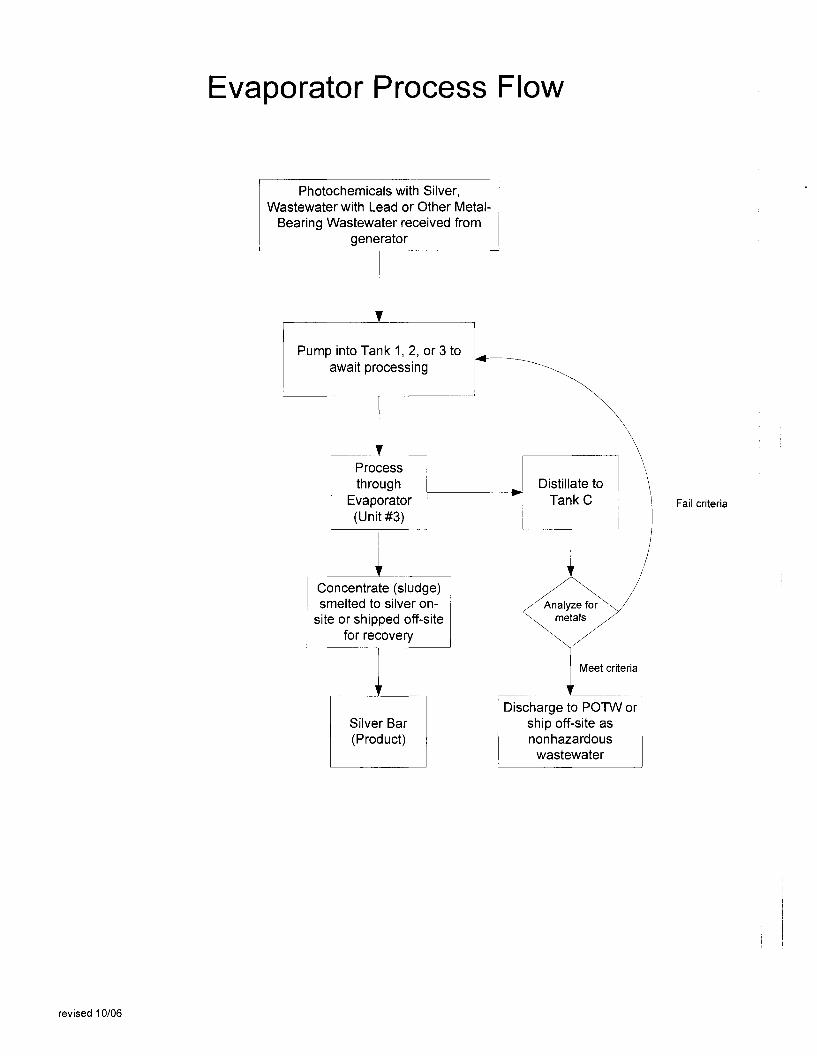
Evaporator Process Flow
Photochemicals with Silver,Wastewater with Lead or Other Metal
Bearing Wastewater received fromgenerator
revised 10/06
Pump into Tank 1, 2, or 3 toawait processing
Ir
Processthrough
Evaporator(Unit #3)
Concentrate (sludge)smelted to silver on
site or shipped off-sitefor recovery
Silver Bar(Product)
...
Distillate toTankC
•
Analyze formetals
Meet criteria
Discharge to POTW orship off-site asnonhazardous
wastewater
Fail criteria

Crucible Furnace or Hot Pot Process Flow
Material added to crucible-may be silver flake,other metal-bearing sludge or metal dust
Fluxing Agents added-varydepending on melt, but mayinclude soda ash, lime, sulfur
Furnace heated to1700-2200F
Slag (Byproduct)
1
revised 10/06
Molten metal poured into ingots(Product)
Ir
Analyzed for metalcontent (QAlQC)
Ingots sold torefiners
Ir
Shipped offsite to smelterfor recycling

Solder Dross Process Flow Diagram
Solder Dross Received from Generator
Visual waste analysisSampled and analyzed for metal
content for QA/QC purposes
Shipped to ECS Texas for
Recycling
ECS Refining9/2007

Solder Paste and Wipes Process Flow
MaterialTin/lead (or other metal) paste
shipped toECS Texas for
and wipes received from
recyclinggenerator
Material manuallyadded to trays to feed
into Tray Furnace (Unit#15)
Materialprocessed at
high heat
~ Ash (By-product)
,
Molten metal poured Irinto ingots(Product)
Shipped to ECSTexas or other
recycler
Ingots sold tometal refiners
revised 10/06

E-WASTE/PRINTED CIRCUIT BOARD SHREDDER
UNIT #27
PROCESS FLOW DIAGRAM
E-waste or PCBdScrap
SSI 5000HShredder
Shredded Product
Shipped to smelter for
recovery
ECS 11/2007

CRT GLASS WASHING UNITUNIT #28
PROCESS FLOW DIAGRAM
Broken CRT Glass
Wash with Proprietary
Solution
Rinse with Water
Glass shipped to smelter or glass
recycler
ECS 11/2007
Coatings shipped off-site for
treatment or recoveryNote: Wash water and
rinse water re-used until spent, then treated and discharged to POTW
under permit, or shipped off-site

Computer Monitor/CRT DeviceProcess Flow Diagram
Monitor orCRT DeviceReceived at
Facility
,
Plastic housing Plastic baledmanually f-------I~ for shipment toremoved plastic recycler
--------
Cathode raytube
Cathode raytube separated ~
~-----I from f--------.J
electronics
Electronicfraction
Copperyoke torecycler
Copper yoke.---- manually
removed
Shredded inSSI RotaryShredder
Magnetic separator
CRT to glasscrusher
Ferrousscrap
fraction
Nonferrousscrap
fraction
Eddy current
Othermetal
fraction
AluminumFraction
~~----.~~PCBdPlastic
Fraction
,To steelrecycler
Crushed CRTGlass
Metal Frames
,Each fraction sent torespective recycler
,-----'---
To steelrecycler for
recovery
Crushed glassto lead smelter
for recovery
Note: This is not aregulated hazardous
waste treatment activity.
ECS Refining10/2006

Universal Waste Electronic DevicesProcess Flow Diagram
Receive Send to UDT ifUWED at ECS f--~~~--Ip~ client wants to
Refining resell
Shred
Magnetic separator
Ferrousfraction
Shipped tosteel recyclerfor recovery
Nonferrousfraction
Eddy current
PCBd andPlastic
Fraction
AluminumFraction
Other MetalFraction
ECS Refining10/2006
Note: This process is nota regulated hazardous
waste treatment activity.
Each fraction sent to respective recycling outlet

SECTION III
WASTE ANALYSIS PLAN

revised 11/07 III-1
SECTION III WASTE ANALYSIS PLAN The purpose of this plan is to describe the procedures and methods ECS Refining will use to determine whether wastes submitted for recycling meet the facility’s acceptance criteria. There are two phases of this process: pre-acceptance screening, and examination of the containers upon arrival at ECS Refining for conformance to the wastes identified on the client’s profile. The wastes accepted for recycling at ECS Refining are process-specific waste streams that are readily identifiable by appearance and are generated by many businesses throughout the state. For example, tin/lead solder dross is readily recognizable to the trained eye. Therefore, confirmation that the waste conforms to the profile does not necessarily require analytical testing. A. Description of Waste Types A complete list of all waste stream types accepted and managed at ECS Refining is included as an appendix to this Waste Analysis Plan (see Table III-A, attached). This table lists the waste streams, assigns each waste stream a unique letter identifier, lists the applicable state and federal waste codes, gives the hazards posed by the waste, the hazardous constituents, and provides a description of the process generating the waste. Both hazardous and non-hazardous wastes that are handled at the facility are included in the table for explanatory purposes. The wastes handled at ECS Refining that are non-hazardous are not required to be sampled as the hazardous wastes are, and are only included in this table for clarification of all types of materials handled. B. Pre-Acceptance Criteria All generators are required to submit written waste profiles for each waste stream prior to shipping the material to ECS Refining for recycling. Example waste profile sheets are included as Appendix III-B to this section. Waste profiles are accepted online, by fax, and by mail. In most cases, the submittal of a waste profile provides sufficient information to approve the material. For wastes that differ from the routinely accepted tin/lead solder dross, tin/lead and other metal solder pastes and wipes and the photographic wastes, additional information may be requested from the generator. Depending upon the waste, ECS Refining may require a more detailed description of the process and raw materials that generated the waste, copies of material safety data sheets, analytical results, or submittal of a sample of the waste. Waste profiles are reviewed at ECS Refining for conformity with waste acceptance guidelines, are approved by the Environmental Department, and generators are issued an acceptance letter notifying them that the waste as profiled is acceptable at ECS Refining for recycling. The following tables delineate the pre-acceptance criteria for each incoming waste stream that will be used to determine whether a waste is acceptable for recycling at ECS Refining. The waste stream letter from Table III-A is included for reference.

revised 11/07 III-2
Solder Dross (A), Solder Paste and Wipes (D), Sludge with Silver (I), Off-specification, aged, or surplus inorganics (N), Laboratory chemical waste (O), Metal dust (P), Other metal-bearing sludges (Q), Polymeric resin waste (S), Filters with Silver (T), Filters with Lead (U), Wipes with Silver (V), Miscellaneous Residue with Silver (W), and Miscellaneous Residue with Lead (X) Pre-Acceptance Criteria Test Method Acceptable Results Appearance Observation Waste appearance should be
as normally observed for the waste type. Solder dross is a mixture of metal and metal oxides that is readily identifiable to the trained eye. Paste and wipes is a mixture of partially used tubes or jars of solder paste, along with paper or textile wipes contaminated with solder paste. Other wastes are similarly readily identifiable to the trained eye.
Liquid Photochemicals with Silver (F) Pre-Acceptance Criteria Test Method Acceptable Result Appearance Observation Clear to dark brown liquid
with photochemical odor. Material should not have the smell of an organic solvent. If solvent is suspected, mix the waste sample with an aliquot of water to determine if the material is miscible in water. Materials that are not miscible in water are unacceptable.
pH pH Meter or Test Paper 2.5 – 11.5 Metal-Bearing Wastewaters (Y) Pre-Acceptance Criteria Test Method Acceptable Result Appearance Observation Material should not have
the smell of an organic

revised 11/07 III-3
solvent. If solvent is suspected, mix the waste sample with an aliquot of water to determine if the material is miscible in water. Materials that are not miscible in water are unacceptable.
pH pH Meter or Test Paper 2.5 – 11.5 C. Inspection of Incoming Waste Streams Once a shipment of waste arrives at ECS Refining, the personnel in the Receiving Area examine the manifest and shipping documents to ensure they are properly completed. Any discrepancies are handled by contacting the generator for clarification. At least ten percent of the containers of hazardous waste received will be systematically sampled to ensure that the materials conform to that profiled. Wastes will be examined according to the provisions of the pre-acceptance criteria outlined in this waste analysis plan. The waste analysis results are recorded on the “Receiving Waste Analysis Log”, a copy of which is included as Attachment III-C of this waste analysis plan. Sampling methods for solid materials that only require a visual observation check to ensure the waste meets the acceptance criteria are to open the drum or container and examine the contents. Any wastes that do not appear to conform to the expected appearance standard of the waste may be sampled and analyzed. Samples will be taken with scoops dedicated for sampling. Liquids will be sampled with a drum thief and the sample placed in a plastic bottle for examination. D. Outgoing Waste Shipments ECS Refining ships only one by-product as a hazardous waste, the tray furnace ash. This material is produced by one process only, and is shipped to ECS Refining’s sister facility ECS Texas for recovery. Consequently, no analytical testing is required to determine whether the material meets TSD specifications. E. Periodic Generator Profile Verification Generator’s are required to submit an update to their waste stream profiles annually, or whenever their process that generates the waste changes.

Table III-ADescription of Waste Streams
Waste Common Name of U.S. EPA CaliforniaStream Hazardous Waste WasteLetter Waste Code Code Hazard Description of Waste Process Generating Waste
A Solder Dross D008 181 Toxic A mixture of tin/lead alloy and oxides Electronics assembly; other solderingD005 produced during soldering. May also operations.D006 contain other metals in excess of TTLC.D007D011 May contain precious metals. RCRA-exempt characteristic by-product.
B Waste Oil none 221 Toxic Waste oil generated in maintenance Maintenance activities on-site.activities
RCRA-exempt petroleum product.
C Tin/Lead Oxides D008 181 Toxic The tin/lead oxide portion of the dross. Melting tin/lead dross to recover alloy D005 Material is an outgoing by-product. allows separate recovery of the oxideD006 May contain precious metals. layer.D007D011
D Solder Paste and D008 181 Toxic Off-specification or used solder paste jars Surface mount technology.Wipes D005 and cartridges; tissue wipes contaminated
D006 with solder paste. Solder pastes areD007 typically tin/lead, though they may containD011 other metals.
May contain precious metals.
E Ash D008 181 Toxic Metal-bearing ash. Recovered from melting solder pasteD005 Material is an outgoing by-product. into ingots.D006 May contain precious metals.D007D011
F Photochemicals D011 541 Toxic Spent silver-bearing photographic and X-ray Photographic processing, printing, and with Silver D007 developing and printing waste solutions. X-ray developing industries.
May contain precious metals.
revised 12/2007

Table III-ADescription of Waste Streams
Waste Common Name of U.S. EPA CaliforniaStream Hazardous Waste WasteLetter Waste Code Code Hazard Description of Waste Process Generating Waste
G Treated Effluent None None None Treated wastewater that meets local Recovery of silver from photographicindustrial discharge limits. wastewaters.Material is an outgoing by-product. Recovery of metals from other metal-
bearing wastewaters.
H Steel Wool None None None May contain precious metals. Treatment of silver-bearing wastewaters.Recovery Column Not regulated when recycled. RCRA-exempt characteristic sludge.(or Cartridge)
I Sludge with Silver D011 171 Toxic Unspecified sludge with silver Treatment of silver-bearing wastewaters.D007 541 Contains precious metals RCRA-exempt characteristic sludge.
J Dry sludge with None None Toxic Unspecified sludge with silver after drying Treatment of sludge with silverSilver Contains precious metals Product material
K Ag/Fe Pulp None None Toxic Dry, milled silver/iron powder Treatment of steel wool columnsContains precious metals Product material
L Silver Flake None None Toxic High grade silver chips Electrolytic recovery of silver fromContains precious metals photoprocessing wastewaters.Not regulated when recycled. RCRA-exempt characteristic sludge.
M Slag none none Toxic Glassy metal-bearing solid High-temperature metal recoveryMaterial is an outgoing by-product. non-RCRA by-product
N Off-specification D008 141 Toxic Metal bearing inorganic waste Manufacturing processesaged or surplus D004inorganics D005 May contain precious metals. RCRA-exempt commercial chemical
D006 products that exhibit a characteristicD007D010D011
revised 12/2007

Table III-ADescription of Waste Streams
Waste Common Name of U.S. EPA CaliforniaStream Hazardous Waste WasteLetter Waste Code Code Hazard Description of Waste Process Generating Waste
O Laboratory D004 551 Toxic Small quantities of compatible Laboratory research operationschemical waste D005 metal-bearing laboratory wastes
D006 RCRA-exempt commercial chemicalD007 May contain precious metals. products that exhibit a characteristicD008D010D011
P Metal dust D004 172 Toxic Metal dust/machining waste Metal product manufacturingD005D006 May contain precious metals RCRA-exempt characteristic D007 by-productD008D010D011
Q Other metal- D004 171 Toxic Metal-bearing sludges. Characteristic sludges that may bebearing sludges D005 491 reclaimed.
D006D007 RCRA-exempt characteristic by-product.D008D010D011
R Baghouse waste D004 591 Toxic Metal-bearing baghouse waste Air pollution control sludge fromD005 Material is an outgoing by-product. manufacturing processes.D006 May contain precious metals.D007D008 RCRA-exempt characteristic sludge.D010D011
revised 12/2007

Table III-ADescription of Waste Streams
Waste Common Name of U.S. EPA CaliforniaStream Hazardous Waste WasteLetter Waste Code Code Hazard Description of Waste Process Generating Waste
S Polymeric resin D004 272 Toxic Ion exchange resin loaded with metals. Wastewater treatment.waste D005 541
D006 May contain precious metals. RCRA-exempt characteristic sludge.D007D008D010D011
T Filters with Silver D011 171 Toxic Filters with silver residue Filtration of silver-bearing wastewaters.541 Contains precious metals. RCRA-exempt characteristic sludge.
U Filters with Lead D008 171 Toxic Filters with lead residue Filtration of lead-bearing wastewaters.RCRA-exempt characteristic sludge.
V Wipes with Silver D011 181 Toxic Textile or other absorbent wipes Surface mount technology541 contaminated with silver Spill clean up
Contains precious metals.
W Miscellaneous D011 181 Toxic Materials contaminated with Spill clean up; used equipmentResidue with Silver silver
Contains precious metals
X Miscellaneous D008 181 Toxic Materials contaminated with Spill clean up; used equipmentResidue with Lead lead
Y Metal-bearing D004 121 Toxic Metal-bearing wastewaters Characteristic wastewaters fromwastewaters D005 132 manufacturing processes.
D006 135 May contain precious metalsD007 721D008 722D010 724D011 726
727/728
revised 12/2007

Table III-ADescription of Waste Streams
Waste Common Name of U.S. EPA CaliforniaStream non-Hazardous Waste WasteLetter Waste Code Code Hazard Description of Waste Process Generating Waste
Z Router Dust none none Toxic Drill dust containing copper and lead, Printed circuit board manufacturealong with fiberglass
Regulated as an excluded recyclablematerial.
AA Computer monitors none none Toxic Discarded cathode ray tubes, computer Manufacturing scrap or end of life Cathode ray tubes monitors, or televisions generation by consumers and businessTelevisions
Regulated as universal waste.
BB Electronic Scrap none none Toxic Consumer electronic scrap End of life discarded electronics fromconsumers and businesses
Regulated as universal waste.
CC Batteries none none Toxic Nickel/cadmium, lithium, lead, and zinc End of life discarded materialcontaining batteries removed from electronic scrap Regulated as a universal waste.
DD Fluorescent light none none Toxic Fluorescent light fixtures containing Regulated as a universal waste.tubes mercury
revised 12/2007

APPENDIX III-B
Example Waste ProiIle Sheets
Tin/Lead Solder Dross and Related ItemsPhotoechemicals with Silver and Related Items

WASTE PROFILE
Profile #:
Env. Appr.
Entered By
Enter Date
Salesperson------
GENERAL INFORMATION
1. Generator Name: ~ _ Billing Address: D Same _
2. Generator Address: _
3. Technical Contact/Phone: _ Billing Contact/Phone: _
4. Generator USEPA 10: _ Haz. Tax 10: _
WASTE DESCRIPTION
5. Process Generating Waste: _
6. Waste Name: (Circle one)Solder Dross Solder Dross w/Oil Residue Other Lead Residue _
Other _
Other _None
Solid witrace of Oil
Odor:
Solid
Other _
7. Physical State: (Circle one)
Color: Greyish Silver
Spec.Grav.: 7.28-8.42 Other _ Flash Point: No Flash<400'F Other _
___ ppm
___ ppm
CHEMICAL COMPOSITION8. Metal Content: Tin %
Lead %
Other %
Other %
Other %
Organic Mat'l Content: Oil (specify type) _
Cyanid•• 0 ppm Other:sulfid•• 0 ppmPCB'. 0 ppmDioxins 0 ppm
--_%
--_%
SHIppING INFORMATION
9. DOT Shipping Name: RO, Hazardous Waste Solid, n.o.s., Class 9, NA3077,Packing Group III (Lead)
Extra Information: Contains Lead Dross EPA Waste Code: Exempt(Dross); D008(Solids, paste, wipes,etc.)CA Waste Code: 181
Additional Information/Generator Certification
10. _
This is to certify that the information submitted is complete and accurate, and that all known or suspected hazards have beendisclosed. This waste does not contain any radioactive, biological, pathogenic, and/or etiological agents. I agree to notify ECSof any changes in this wastestream by submitting an updated waste profile sheet.
Authorized Signature Title
Name (print) DateECS 5193
* Printed on Recycled Paper
705 REED STREET. SANTA CLARA, CA 95050. (408) 988-4386 • FAX (408) 988-5154Environmentally Safe Recycling of Precious Metals • Photoprocessing Wastes • Tin/Lead Residues
A Permitted Facility and Transporter

GENERAL INFORMATION
RE~INING
WASTE PROFILE
profile It:
Env. Appro·/al _
~nt;r9d By
Entar Data
Salesperson
EPA 10# ~ _1. Generator Name: -- _
2.Site Address: _ Mailing Address: D Same
3. Technical Contact:
4. Telephone:
5. Fax:
Haz.Tax 10 #
Contact: - _
Telephone: ( __ ) _
(Thi3 is not your F"'dtlral TaxpaVt,r l.D. numbor~S~ instructions)
WASTE PESCRIPTION
5. Generating Process Description:
6. Waste Name (Check One):
0 Liquid Photochemical Waste 0 Metallic Replacement Cartridge 0 Silver Flake 0 Filters with Silver
0 Silver Sludge 0 Other (specify) -7. Film Process: -
Check all solutions which will contribute to this waste stream:
0 Developer 0 FIXer 0 Bleach 0 Stabilizer 0 Other (specify)
8. Paper Process:
Check all solutions which will contribute to this waste stream:
0 Developer 0 Fixer 0 Bleach/Fix 0 Stabilizer 0 Other (specify)
SHIPPING INFORMATION (Check One· See Instructions)
0 RO, Hazardous Waste Liquid, n.o.s., Class 9, NA3082, PGIII (Silver) EPA Waste Code: 00'11 CA Waste Code: 541
Addition;,tl Descriptio n: Photochemicals with Silver .'0 RO. Hazardous Waste Solid. n.o.s., Class 9, NA3077. PGIII (Silver) EP/~ Waste Code: Exemot CA Waste Code: 171
Additional Description: (Circle One): Cartridge. Steel Wool with Silver Silver Flake Silver Slydge Filters with Silym
Other (specify)
ADDITIONAL INFORMATION/GENERATOR CERTIFICATION
10. -------------------------------------------
This is to certify that the information submitted is complete and accurate. and that all known or suspected hazards have beendisclosed. This waste does not contain any radioactive. biological. pathogenic. and/or etiologic agents. ~ agll'ee to notity
of any changes In thoa compoz;ition of this wa:.'it.e stream !by submitting anupdated waste profile sheet.
Authorized Signature
Print NameRev 593
Title
Date

Receiving Waste Analysis LogWaste Analysis Plan Attachment III-C
RESULTS
Date Manifest No. of Sampled? Container pH (OK =
Received Number Containers (Yes/No) Sampled 2.5-11.5) Visual Other Comments or Analvses
revised 10/06

SECTION IV
FACILITY DESIGN (STORAGE)

revised 2/21/2008 IV-1
SECTION IV – FACILITY DESIGN (STORAGE) A. STORAGE AREAS FOR DRUMS / CONTAINERS / TANKS / OTHER
DEVICES
1. How many storage areas do you have or plan to have? In the facility plot plan, indicate where your storage areas are, how you will arrange the storage devices (including length of each row, aisle space). See Notes, below;
The facility maintains four storage areas for hazardous wastes, and additional storage area for non-hazardous or universal wastes. See the facility plot plan in Section II for the facility layout. Aisle space is maintained at 24 inches, as agreed upon as a condition of the previously granted standardized permit and in accordance with the City of Santa Clara requirements. 2. What are the dimensions of each storage area? Include the berm
height.
Storage Area I: 10’L x 5’W Storage Area IIa: 47’ 8”L x 27’W x 6”H Storage Area IIb: 85’L x 30’W x 9”H Storage Area III: Not regulated or used for hazardous waste Storage Area IV: 62’L x 58’W
3. How many storage devices do you plan to store in each area?
The following table shows the areas and capacities of the drum storage areas:
Unit Number Storage Area Name Number of Drums Comments 10 Area I 20 Solids only 11a Area IIa 20 Liquids 11b Area IIb 160 Liquids 12 Area III No hazardous
waste in this area
13 Area IV 648 648 drums of solid, liquid or equivalent. Liquids stored in this area are stored on containment pallets.

revised 2/21/2008 IV-2
The following table shows the tank storage capacity. The tanks are used for storage of incoming photochemical and other wastewaters, and are part of the treatment units associated with Unit #1, Silver Recovery Unit, and Unit #3, Vacuum Evaporation Unit.
Tank Number Capacity (gallons) Location Tank A 3,000 Area IIa Tank B 3,000 Area IIa Tank 1 2,500 Area IIb Tank 2 2,500 Area IIb Tank 3 2,500 Area IIb Tank C 3,200 Area IIb Three tanks were permitted in the standardized permit issued 12/30/1997 that will be removed before this permit is approved. They are Tank D, Tank E, and Tank F located on the mezzanine in Storage Area IIa.
4. What are the sizes of the storage devices?
Containers stored are typically 55-gallon drums, either high density polyethylene or steel construction. However, smaller drums and containers may be stored, such as 30-gallon, 15-gallon, and 5-gallon.
5. Do you stack storage devices? You may not stack more than two
containers high. Containers and drums are usually double-stacked.
6. All waste must be stored in DOT (Department of Transportation)
approved storage devices. Of what materials are your storage devices made?
The drums are constructed of steel or HDPE (High Density Polyethylene). The tanks are constructed of HDPE (High Density Polyethylene). Non-hazardous and universal waste electronic scrap or CRT devices are stored directly on pallets and secured with shrink wrap, or are stored in cubic yard Gaylord boxes constructed of cardboard.
7. Are or will any storage devices be kept outside? If so, describe the
measures taken to protect hazardous waste /devices that are subject to corrosion or deterioration from the weather (e.g. roofs, tarps, awnings, and elevation of containers above ground surface)

revised 2/21/2008 IV-3
Hazardous wastes are not stored outside, though they may be stored in Area IIb, which is an outdoor area covered by a roof and surrounded by a containment berm with sufficient containment capacity for the materials stored there.
8. Will liners be used in any of the storage devices holding hazardous
waste? If so, explain how the empty storage devices or liners are or will be managed or disposed.
Liners are not typically used in any of the storage devices.
9. How do you track your storage devices management and movement
(e.g., receiving to offsite shipment)? The facility maintains a computerized inventory control system. Upon receipt at the facility, each container is affixed with a bar code label to track its progress through the facility. Upon processing of the container, the bar code is scanned and marked as “processed” into a particular outgoing lot. This enables the facility management to search the computerized inventory for containers of hazardous waste currently in inventory, to determine the particular day a container is processed and into which outgoing shipment it went.
10. How do you make sure that any incompatible wastes are separated? The facility does not receive and store any incompatible wastes.
11. How often do you inspect your storage devices? You are required to
inspect the container storage areas at least weekly, daily for tank storage area and look for leaking containers and for deterioration of storage devices and the containment system caused by corrosion or other factors. A storage device holding hazardous waste must always be closed during transfer and storage, except when it is necessary to add or remove waste.
The container storage areas are inspected weekly for integrity and capacity. The tank storage areas are inspected daily. See the Inspection Plan for further details on each of these required inspections.
B. HAZARDOUS WASTES STORED
Provide the name and describe the physical properties of each hazardous waste that is or will be stored in each area. Be sure that the information

revised 2/21/2008 IV-4
includes all of the following: 1. Common waste chemical name(s) 2. EPA and/or California hazardous waste number(s) 3. Specific gravity 4. Vapor pressure, if applicable 5. Flame point/auto-ignition temperature, if applicable 6. pH 7. Color 8. Others (to be completed by Applicant) See attached Table IV-1 for this information.
C. STORAGE DEVICE / EQUIPMENT DESCRIPTION
List all devices/equipment to be used in each storage area, including containers, totes, bags, tanks, reactors, vats, etc. Describe the following if they apply to the equipment (excluding DOT-drums); 1. Internal and/or external dimensions in feet and inches 2. Internal design capacity in gallons Tank Capacities and Dimensions
Tank Number Capacity (gallons) and Type
Internal Dimensions (d x h)
Tank A 3,000 cone-bottom 95” x 121” Tank B 3,000 cone-bottom 95” x 121” Tank 1 2,500 cone-bottom 95” x 105” Tank 2 2,500 cone-bottom 95” x 105” Tank 3 2,500 cone-bottom 95” x 105” Tank C 3,200 flat-bottom 95” x 112”
Container Dimensions and Capacities
Capacity (gallons) Type Dimensions (d x h) 85 HDPE Overpack 31” x 33” 55 Steel 24” x 35” 55 HDPE 23” x 35” 30 Steel 20” x 29” 30 HDPE 19” x 29.5” 15 HDPE 15” x 22.5” 5 Steel bucket 12” x 13.5” 5 HDPE 11” x 10” x 14” (l x w x h)

revised 2/21/2008 IV-5
Age of each tank (new or from the operating records of the facility) Tank Number Capacity (gallons) Installation Date Tank A 3,000 February 2001 Tank B 3,000 February 2001 Tank 1 2,500 April 1994 Tank 2 2,500 April 1994 Tank 3 2,500 April 2001 Tank C 3,200 April 1994 Note: This information on tank capacities and dimensions reflects the tank status after closure of Tanks D, E, and F, to be completed before this permit is issued.
3. If the equipment will be coated or lined, describe the lining and/or coating material and thickness used inside or outside
The containers and tanks are not lined.
D. SECONDARY CONTAINMENT SYSTEM FOR STORAGE AREAS
Each storage area where liquid wastes are stored must have a secondary containment into which the storage devices are placed. The Applicant shall include an Engineer Certification which describes the containment designs. See Subsection G for details on certification. The Professional Engineer’s certification is included as part of this submittal.
E. STORAGE OF IGNITABLE, CORROSIVE, OR REACTIVE HAZARDOUS WASTE
1. If the Facility will transfer, or store ignitable, corrosive or reactive
wastes, in the facility plot plan, show the locations where equipment holding ignitable or reactive hazardous wastes are or will be stored at the facility and their protective distances or buffer zone of at least 50 feet from the facility's property line. Show on the plan the minimum protective buffer distance required around each tank(s) in accordance with Table 2-1 through 2-6 of the National Fire Protection Association's "Flammable and Combustible Liquids Code". Data is available from the National Fire Protection Association, 1 Batterypark, Quincy, MA. 02267, Phone: (800) 344-3555.
The facility does not treat or store ignitable, corrosive, or reactive wastes. However, flammable, corrosive, or reactive wastes may be handled on a transfer basis. This activity falls under the

revised 2/21/2008 IV-6
transportation of hazardous waste rules. The drums that are handled on a transfer basis are stored for less than ten days as allowed by Title 22, Section 66263.18 in the facility Receiving Area. The Receiving Area is at least fifty feet from the property line. These wastes handled on a transfer basis are not incompatible with facility hazardous wastes that are stored and processed. 2. Describe the precautions taken by the facility, e.g. distances of
separation between incompatible wastes and the locations of dikes, berms, or walls used to maintain the separation, to prevent reactions involving ignitable or reactive wastes which would result in any of the following:
This section not applicable.
a. Generate extreme heat or pressure, fire or explosions, or violent reactions
b. Produce uncontrolled flammable fumes, dusts, or gases in
sufficient quantities to threaten human health or the environment
c. Produce uncontrolled flammable fumes or gases in sufficient quantity to pose a risk of fire or explosions
d. Damage the structural integrity of the container or the facility
e. Through other means threaten human health or the environment
F. SPECIFIED AIR EMISSIONS CONTROLS
Review CCR, Title 22, section 66264.1082 (Air Emission Standards for Tanks, Surface Impoundments, and Containers) to determine whether the regulations apply at your facility. Provide all of the applicable information specified in CCR, title 22, section 66270.27 “Specific Part B Information Requirements for Air Emission Controls for Tanks, Surface Impoundments, and Containers” that applies to containers or tanks.
Air emission controls are not required for ECS Refining’s storage tanks or containers. G. ENGINEER’S CERTIFICATION
1. Engineering Certification of Tank Integrity
The purpose of this engineering certification is to verify that the tanks used to store or treat hazardous wastes have been adequately

revised 2/21/2008 IV-7
designed for this service. A tank integrity certification shall be prepared by an independent, qualified professional engineer registered in the State of California. The tank integrity certification shall include and address the following requirements: a. Tanks shall have sufficient shell strength to assure that they do
not collapse or rupture. This shall be verified by sonic testing to determine the actual shell thickness of each tank. Actual thicknesses shall be compared to the calculated minimum shell thickness based on operating temperature, pressure, and specific gravities of fluids stored.
b. A statement that the tank material of construction is compatible
with the hazardous waste contents.
c. Description of tank system piping (materials of construction, pipe diameter)
d. Description of any internal or external pumps
e. Description of design standard(s), if available, according to which
tank and ancillary equipment were constructed.
f. Description of any spill prevention or overfill equipment
g. Description of any corrosion protection measures
h. Description of any structural damage or inadequate construction such as cracks punctures or damaged fittings. All shall be documented in the assessment and remedied before the tank system is certified for use.
i. Description of any leak detection equipment
j. Information on the documented age of the tank system.
Estimated remaining service life based on findings.
k. Leak test report that verifies current tank and attachments integrity.
l. The certification by the independent engineer shall be written in
accordance with the format specified in California Code of Regulations (CCR), title 22, section 66270.11(d).
2. Engineering Certification of Tank Secondary Containment

revised 2/21/2008 IV-8
The purpose of the certification of the tanks secondary containment system is to confirm that there will not be any releases of hazardous waste contents to subsoil or surrounding areas in the event of a tank failure or spillage.
The secondary containment for above-ground tank systems shall include and address the following requirements:
a. Secondary containment volume shall be greater than either 10%
of the total volume of all tanks or 100% of the largest tank volume, whichever greater, plus the volume of rainfall from a 24-hour, 25-year rainstorm.
b. The secondary containment pad and berms shall be coated with a
material, to make an impervious barrier and prevent migration of spilled liquids.
c. The coating material, used for the coating, shall be compatible
with the wastes handled in the tank system.
d. The secondary containment shall have sufficient structural strength and thickness to prevent failure due to pressure gradients, physical contact with the waste to which it is exposed, climatic conditions, and the stress of daily operation.
e. The secondary containment foundation should be capable of
providing support, resistance to pressure gradients above and below the system and capable of preventing failure due to settlement, compression or uplift. The base shall be free from cracks or gaps.
f. Verification that the secondary containment system has a leak-
detection system that is designed and operated so that it will detect the failure of either the primary or secondary containment structure or the presence of any released of hazardous waste or accumulated liquid in the secondary containment system within 24 hours.
g. Verification of slope design and designed to remove liquids
resulting from leaks, spills or precipitation.
h. Designed or operated to prevent run-on and infiltration of precipitation into the secondary containment system from other areas within the facility.
i. The certification by the independent engineer shall be written in

revised 2/21/2008 IV-9
accordance with the format specified in CCR, title 22, section 66270.11(d).
The secondary containment system for below-ground tank systems shall include the following: a. Designed or operated to contain precipitation from a 24-hour, 25-
year storm event plus the greatest of 10% of the aggregate volume of all tanks or 100% of the capacity of the largest tank within its boundary.
b. Designed or operated to prevent run-on and infiltration of
precipitation into the secondary containment system unless the collection system has sufficient excess capacity, in addition to that required above
c. Constructed with chemical-resistant water stops in place at all
joints. (if any) d. Interior impermeable coating or lining compatible with the waste
being stored in order to prevent migration of waste into the concrete
e. It should be protected against the formation of and ignition of
vapors within the vault f. The certification by the independent engineer shall be written in
accordance to the format specified in CCR, title 22, section 66270.11(d).
Secondary Containment can also be provided by utilizing double-walled tanks. The secondary containment certification for double-walled tank systems shall include the following: a. Designed as an integral structure so that any release from the
inner tank is contained by the outer shell.
b. Protect, if constructed of metal, from both corrosion of the primary tank interior and of the external surface of the outer shell.
c. Provide with a built-in continuous leak detection system capable of detecting a release within 24 hours.
d. Verification that all auxiliary equipment shall be provided with secondary containment.

revised 2/21/2008 IV-10
e. The certification by the independent engineer shall be written in accordance with the format specified in CCR, title 22, section 22670-11)(d).
3. Engineering Certification of Secondary Containment of Container
Storage Areas.
The engineering certification for the secondary containment of container storage areas is the same as that for tank storage areas. The only different requirements would be the following:
a. The containment system shall have sufficient capacity to contain
precipitation from at least 24-hour, 25-year storm plus 20% of the aggregate volume of all containers or the volume of the largest container, whichever is greater. Containers that do not contain free liquids need not be considered in this determination.
4. Engineering Certification of Compliance with Seismic Standards
The tank integrity assessment shall also include calculations in order to show that supporting structures are of sufficient strength to withstand a seismic event. This calculation will include a ground acceleration factor based on current earthquake fault data in the vicinity of the facility. DTSC is required to issue hazardous waste facility permits which meet the building standards published in the state building standards code per health and safety code section 25200(a).
H. ENGINEER'S QUALIFICATION
1. Name of the registered engineer 2. Registration number
3. Engineering discipline
4. Date of expiration of the engineer's registration
The Engineer’s Certification as required by this section is located in Appendix E.

Tab,~ IV-1Physical Properties of Wastes in Each Storage Area
WasteStream Letter
Common Name ofHazardous Waste
EPA Waste CaliforniaCode Waste Code
SpecificGravity pH
FlashPoint
Possible StorageArea
ABCDEFGHIJKLMN
oPQ
RSTUV
Wxy
ZAABBCCDO
none 181N/A 221
none 181D008 181D008 1810011 541none none
Not HW Not HWnone 171
Not HW Not HW-------------------- ---- --
Not HW Not HWNot HW Not HW
---- -~----_.- ---
Not HW Not HW-------~_.__ .. _- -----
D008* 141
591272171171181181181
121 *NotHWNotHWNot HW-- - ------------ - -'---- ----- ------- ----
Not HWNot HW
7.2-8.40.7-0.97.5-8.5N/AvN/Av
1.1-1.41.0-1.2N/AvN/AvN/AvN/Av
10.2-10.5N/Av
1.0-10.0-----_.._-------
N/AjJN/ApN/Ap
. f\J/~rJN/Ap
4.0-12.05.0-12.0
t\i/ApN/Ap
. !'J/Ap_f\j/Ap!'J/Ap_N/Ap
1'J/.A2_
t"-J/.ArJ. I, IV>150F I, IV, MaintenanceN/A'p_ I, IV
.NJ,il.rJ_ I, IVN/Ap I, IVt\i/,il..P_____ lIa, lib, IV
I'J/j.\p .~Cl,Jlb_N/Ap lIa, lib, IV.f'J/!'-P Ila,_lIb,_IVN/Ap ThrolJ.9.hout facility
_. f\J!.~_._._ ·T"~rougtl.~~!.~~ili!y
. t'J/J.\Pl"~r~~~hout facilityI'J/Ap Ihr()ughout fCl(~ility_
N/Ap I, lIa, lib, IV
* See Waste.A~Cllysis PICl~.!or.
additional waste codes that apply
revised 11/2007----- - --------------

~
47'8" ~
30'
o
~
g~~ 8:>~~
k<.c,,- J[kJ
DECANTINGTABLES
It!
Ift!\~
'0
~
Tanks will be removed prior to 12/07I
~
oc~~.~
Drum Pump Station
! "~"""~~'~'~"~~'~''''''''''''''''''''''''~''''''~'''''>:: ~'''~I '""' ,,~, ,~
~~~
Unit 1//,. '1' "''',,- ,.-,,- =r" '",
,IF) ;' [E) \ / 101 ':!1500 GAL. C.B. ' 1500 GAL. C.B.! : 1500 GAL. C,S' i\ BaN x 118# \ 88# X 118- / \ 8S# X 118" /
"-,", _/ '---------,,/ "',-,--.---/ncorD
_-;::::::====1===1=1::::::==1t ~;;m;g;;;;!:mI]!fEI @~1fm;fn~K;r ;mfIri~m".fiiE1i1I=iE;;;;;n:! ;: ;: ;; W&»MI I ~.c .. ... • ...,
23
----I...-*',,""""""""~"""""""""""""""""""""""'"''''''''''''''''''''''''''''''''''''''''''''''''''''''''''''''""",,,,,,,,,,,,,,,,,,,,,, ....,,,,,,,,,,,,,,,,,,,,,,,,,,,,,,,,,,"''''"~ ..."""""",,,,,,,,,,,,,,,,,,,,,,~,,,,,,,,,,,,,,,,"""""""""""''''''''''~
I· 85' ·1
PROCESS FLOWIPIPING LAYOUT-PHOTOCHEMICAL TREATMENT UNIT 1ECS Refining
705 Reed Street
Santa Clara, CA 95050'--------------------------
Figwc
2

6-inches
/ T "
6-inches
Berm Depth
11 7/16"-inches 17-incnes
10"-inches
South Bermed Area
,
6-inches
6-incJies
/ "6-inches

SECTION V
FACILITY DESIGN (TANKS)

4/1/2008 V-1
SECTION V – FACILITY DESIGN (TREATMENT) Unit #1–Photochemical Processing Unit
Unit #3—Vacuum Evaporation Unit A. TREATMENT PROCESS DESCRIPTION AND FLOW DIAGRAM
1. Treatment process: Describe in detail all of the chemical treatment processes that are or will be done in
Unit #1 (Photochemical Processing Unit) removes the silver from liquid photochemical waste. There are two types of treatment that may occur using this unit and equipment—either metallic replacement of the silver for iron using metallic replacement cartridges, or using a proprietary chemical (S-ROM) in conjunction with carbon filtration to remove silver from the waste stream. The S-ROM precipitation also has the capability to remove small amounts of other metal contaminants, such as chromium or zinc. The incoming photochemical waste is delivered in drums and containers. It is pumped into holding tanks prior to processing. It will then be processed by one of two methods, depending upon production needs: Metallic Replacement Treatment is accomplished by pumping the photochemical waste waters through reusable cartridges that are packed with steel wool. The iron in the steel wool dissolves into the effluent, and the silver is deposited on the cartridge as silver metal. The resulting effluent may then be sampled and, if local limits are met, discharged to the POTW under permit. Alternatively, the effluent may be sent for off-site discharge as a non-hazardous wastewater if the silver level is below 5 mg/L. This process is not regulated as a hazardous waste treatment activity in California, since SB2111 passed in 1999 mandated that silver-only wastes be regulated in California as they are federally. S-ROM/Carbon Precipitation S-ROM is a chemical precipitant that precipitates various dissolved metals, including silver, chromium and zinc. This process involves adding the S-ROM powder directly to a cone-bottom tank containing photochemical waste. The precipitant is allowed to settle and the treated effluent is pumped through a “mega-filter” packed with carbon and then into another holding tank for sampling. As is the case for the metallic replacement cartridge process, the effluent may either be discharged under permit to the POTW after batch sampling, or may be sent off-site as a non-hazardous wastewater if the metal concentrations are

4/1/2008 V-2
below TCLP and STLC levels. The S-ROM sludge is harvested as needed (generally once per month) and is smelted on-site to produce a silver bar. Unit #3 Vacuum Evaporation Unit is located within the bermed confines of Storage Area IIb. It consists of a double-effect vacuum evaporation unit designed to remove water from wastewaters with metal, primarily photochemicals with silver, but also other metal-bearing wastewaters. The tanks used to feed this unit and to contain the effluent are also used in conjunction with Unit #1. Regardless of treatment method used, the effluent may sometimes fail to meet the local wastewater discharge limits imposed by the POTW. Each batch is sampled prior to discharge to ensure limits are met. Batches that do not meet discharge limits are reprocessed in order to meet the discharge limits.
a. Equipment used Tanks are used to store the photochemicals prior to processing, to treat the waste using the S-ROM precipitant, and to hold the effluent prior to release. Pumps are used to move the photochemicals from one tank through the metallic replacement columns, or through the mega-filter and into the effluent holding tanks. The vacuum evaporation unit has associated with it a boiler and cooling tower. b. Chemicals added Metallic replacement cartridges do not require the addition of any chemicals. S-ROM/Carbon Precipitation Process requires the addition of S-ROM to precipitate the silver (and other metals, if present).
c. Process type (e.g., batch, continuous, etc.) Both the metallic replacement and S-ROM processes are operated on a batch basis. The vacuum evaporation unit may be operated on a batch or continuous basis, but is usually operated as a batch unit.
d. Feed rate (e.g., gal/min., lb/hr., etc.)

4/1/2008 V-3
Unit #1: 1,500 gallons/day Unit #3: 150 gallons/hour or 1,500 gallons/day
e. Chemical reactions, if any Metallic replacement cartridges Fe(s) + Ag2+ → Ag(s) + Fe2+
S-ROM Precipitation Process S-ROM + Ag2+ → S-ROM-Ag(s)
Unit #3—Vacuum Evaporation Unit Wastewater with metals Sludge with metals + Water (heat)
f. Products and by-products for each chemical treatment process Metallic Replacement Cartridges The product is the silver/iron sludge contained in the cartridge, which may be dried and smelted into silver bars. The by-product is treated effluent, which may be either discharged to the POTW or sent off-site as a non-hazardous waste water. S-ROM/Carbon Precipitation Process The product of this process is the S-ROM Silver Sludge harvested from the reaction tank, which is then smelted into silver bars. The by-products of the process are the spent carbon filter with silver and the treated effluent. The carbon filter is shipped off-site for further recovery, and the treated effluent may be either discharged to the POTW or sent off-site as a non-hazardous waste water. Vacuum Evaporation Unit produces a metal-rich sludge as a product and distilled water as a by-product. The sludge may be smelted on-site or shipped off-site for further recovery. The water is either tested for compliance with POTW discharge requirements and discharged to the sewer, or is shipped off-site as a non-hazardous wastewater.
2. Flow Process Diagram: Include a diagram of existing or planned
treatment process unit and associated treatment equipment, including all piping throughout the facility connecting treatment containers, tanks, reactors, vats, etc., showing any valves, plumbing,

4/1/2008 V-4
pumps, process flow direction, etc
In addition, provide the following detailed information, diagrams and drawings for each tank: a. Indicate whether the equipment (e.g. tank) is or will be entirely or
partially above and/or below ground, if applicable. All tanks are located above ground. b. Indicate whether the equipment (e.g. tank) can or will be able to
be entered for inspection and routine maintenance, if applicable. All tanks associated with Unit #1 and Unit #3 may be entered for inspection and routine maintenance. c. Show the aisle space between containers, tanks or other
equipment. See attached drawings.
d. If there is or will be an automatic or manual feed waste safety
cutoff system, describe the hazardous waste feed safety cutoff system, if applicable.
e. If there are or will be tanks that are uncovered and outdoors,
minimum freeboard is required. Provide calculations to show that each open uncovered tank has or will have sufficient containment volume to hold the rainfall from a 24-hour, 25-year storm. Rainfall data may be obtained from the Department of Water Resources, Office of the State Meteorologist, Phone: (916) 653-5791.
Not applicable, as the tanks are located under the roof.
f. If there is or will be a bypass system to a standby tank or a
backup plan to prevent overfills, describe this system or the backup plan.
g. If there are or will be tanks that are airtight, pressurized or under
vacuum, describe the pressure control and/or pressure release controls for closed tanks such as vents and relief valves.
These tanks operate at ambient pressure, as does Unit #1. The Vacuum Evaporation Unit is under pressure. The pressure is produced by aspiration; once the fluid flow is turned off, the vacuum is released. The boiler associated with the unit shuts

4/1/2008 V-5
off if the pressure reaches 125 psi.
h. If there are or will be temperature controls used in any tanks, describe the temperature controls and temperature cutoff safety controls.
There are no temperature controls used in these tanks.
The Vacuum Evaporation Unit is controlled by a standard thermocouple that the operator sets according to a digital control panel. It has a shutoff mechanism if the temperature reaches a pre-set level.
i. If there are or will be liquid level indicators used in tanks, describe the liquid level measurement devices or indicators.
j. If there are or will be tanks that contain volatile hazardous wastes,
describe the pressure relief or tank venting and vapor control systems for these tanks.
None of the wastes are volatile.
k. If there are or will be tanks that are outdoors and made of metal,
describe how each tank is protected from lightning. All tanks are made of HDPE and are located either within the facility or are in a roofed and contained area.
3. For any treatment unit, furnish sampling data that shows the
effectiveness of the treatment. This data should be based on sampling of untreated incoming hazardous waste and waste after treatment. The samples must be tested at a California state certified analytical laboratory.
This waste analysis information is included as an attachment. 4. Provide the following information concerning prevention of releases
to the environment:
a. Describe how the facility does or will prevent any releases of hazardous waste from reaching surface soils, surface water or wetlands.
The tank system and treatment is located in an area especially designed to prevent releases of hazardous wastes from reaching soils. The areas are constructed of cement, and the

4/1/2008 V-6
floor slopes to a sump. Any liquids spilled in the area are pumped back into the tanks for treatment. The cement floor is coated with an epoxy coating. Underneath the cement is a geotextile (Hypalon) liner that will trap any liquid that may seep through cracks in the concrete. b. Describe how the facility does or will prevent any releases of
hazardous waste from reaching the air. Unit #1: The photochemicals are not volatile and do not release hazardous wastes into the air. Unit #3: The purpose of this unit is to produce water vapor. Due to the nature of photochemical waste, some ammonia vapor is also produced. The evaporation system is a closed unit system that recondenses the vapors. When effluent is treated for ammonia prior to discharge to the POTW, ammonia vapors may be released in quantities below the Bay Area Air Quality Management District threshold limits.
B. HAZARDOUS WASTES TREATED
1. Provide the name and describe the physical properties of each hazardous waste that is or will be treated in each process. Be sure that the information includes all of the following:
a. Common waste chemical name(s) Photochemicals with silver (F) Metal-bearing wastewaters (Y) b. EPA and/or California hazardous waste number(s) Photochemicals with Silver EPA: D011 California: 541 D007 Metal-bearing wastewaters EPA: D004 California: 121 D005 132 D006 135 D007 721 D008 722 D010 724 D011 726 727 728

4/1/2008 V-7
c. Specific gravity Approximately 1.1
d. Vapor pressure, if applicable Not Applicable e. Flame point/auto-ignition temperature, if applicable Not applicable
f. pH Approximately 7.5 – 8.5 (Photochemicals with silver) pH of Other metal-bearing wastewaters may fall outside this, between 2.5 and 11.5.
g. Color Clear to light brown
C. TREATMENT DEVICE/EQUIPMENT DESCRIPTION
List all equipment to be used in each treatment process, including containers, tanks, reactors, vats, furnaces, etc. Describe the following if they apply to the equipment (excluding DOT-drums); 1. Internal and/or external dimensions in feet and inches
Note: These tanks are associated with Unit #1 (Steel Wool Column and S-ROM Precipitation Unit, and Unit #3, Vacuum Evaporation Unit). Internal Dimensions (d x h) Type Tank A 95” x 121” Cone bottom Tank B 95” x 121” Cone bottom Tank D 72” x 85” Cone bottom Tank E 62” x 58” Cone bottom Tank F 62” x 58” Cone bottom Tank 1 95” x 105” Cone bottom Tank 2 95” x 105” Cone bottom Tank 3 95” x 121” Cone bottom Tank C 95” x 112” Flat bottom
Note: Tanks D, E, and F will be removed and closed prior to the issuance of this standardized permit. 2. Internal design capacity in gallons
Capacity Tank A 3,000 Tank B 3,000

4/1/2008 V-8
Tank D 1,050 Tank E 750 Tank F 750 Tank 1 2,500 Tank 2 2,500 Tank 3 2,500 Tank C 3,200
Note: Tanks D, E, and F will be removed and closed prior to the issuance of this standardized permit.
3. Shell thickness such as wall, top, and bottom in inches
As specified by the manufacturer, all tank walls vary in thickness along the length of the tank, but are guaranteed to be a minimum of ¼”.
4. Age of each tank (new or from the operating records of the facility)
Installation Date Tank A February 2001 Tank B February 2001 Tank D February 2001 Tank E 1995 Tank F 1995 Tank 1 1/1995 (moved to Area IIb 2/2001) Tank 2 1/1995 (moved to Area IIb 2/2001) Tank 3 April 2001 Tank C April 1994
5. Operating temperature of each tank in degrees Fahrenheit (from
design or from operating records) and operating pressure in psi. All tanks operate at ambient temperature and pressure.
6. If the equipment will be coated or lined, describe the lining and/or coating material and thickness used inside or outside
Not applicable. D. SECONDARY CONTAINMENT DESIGN
Tank system or treatment equipment containing no free liquids and situated inside a building with an impermeable floor are exempt from

4/1/2008 V-9
secondary containment requirements. The Applicant shall include an Engineer Certification which describes the containment designs. See Subsection IV.G for details on certification.
E. TREATMENT OF IGNITABLE, CORROSIVE, OR REACTIVE
HAZARDOUS WASTE
1. If the facility will transfer, treat or store ignitable, corrosive or reactive wastes, in the facility plot plan, show the locations where equipment holding ignitable or reactive hazardous wastes are or will be stored at the facility and their protective distances or buffer zone of at least 50 feet from the facility's property line. Show on the plan the minimum protective buffer distance required around each tank(s) in accordance with Table 2-1 through 2-6 of the National Fire Protection Association's "Flammable and Combustible Liquids Code". Data is available from the National Fire Protection Association, 1 Batterypark, Quincy, MA., 02267, Phone: (800) 344-3555.
2. Describe the precautions taken by the facility, e.g. distances of
separation between incompatible wastes and the locations of dikes, berms, or walls used to maintain the separation, to prevent reactions involving ignitable or reactive wastes which would result in any of the following:
The facility does not handle incompatible wastes. This unit does not transfer, treat or store incompatible, ignitable or reactive wastes.
a. Generate extreme heat or pressure, fire or explosions, or violent
reactions b. Produce uncontrolled flammable fumes, dusts, or gases in
sufficient quantities to threaten human health or the environment
c. Produce uncontrolled flammable fumes or gases in sufficient quantity to pose a risk of fire or explosions
d. Damage the structural integrity of the container or the facility
e. Through other means threaten human health or the environment
F. SPECIFIED AIR EMISSIONS CONTROLS The wastes treated and stored in these tanks do not contain volatile organics and are exempt from the provisions of Title 22, Section

4/1/2008 V-10
66264.1082. The facility does maintain an air permit from the Bay Area Air Quality Management District and no air emission controls are required on this equipment. G. ENGINEER’S CERTIFICATION OF TANK INTEGRITY AND
SECONDARY CONTAINMENT
If treatment is conducted in tanks or containers please refer to Section IV.G for details on tank integrity engineering certification and secondary containment engineering certification.
H. ENGINEER'S QUALIFICATION
1. Refer to Section IV.H for details of Engineer’s qualifications for certifications.

revised 4/1/2008 V-11
SECTION V – FACILITY DESIGN (TREATMENT) Unit #7–Hot Pot Furnace Unit
A. TREATMENT PROCESS DESCRIPTION AND FLOW DIAGRAM
1. Treatment process: Describe in detail all of the chemical treatment processes that are or will be done in
Unit #7 (Hot Pot) is a gas-fired pot crucible furnace used to melt silver flake into silver bars. It may also be used for recovery of small lots of other precious metals such as platinum and palladium. The furnace is generally used for non-hazardous and unregulated wastes.
a. Equipment used Silicon carbide crucible is used and lasts approximately 20 melts. Material is manually added to the crucible using a shovel or scoop. b. Chemicals added Fluxing agents are used to improve the quality of metal recovered and to create the slag that contains the impurities. The specific fluxing agents vary depending upon the type of melt, but may include soda ash, sulfur, or lime.
c. Process type (e.g., batch, continuous, etc.) The furnace operates on a batch basis.
d. Feed rate (e.g., gal/min., lb/hr., etc.) 50 pounds per hour of melt
time.
e. Chemical reactions, if any Metal + Metal Compounds + Fluxing Agents Metal + Slag
f. Products and by-products for each chemical treatment process
Products are metal bars (typically silver, but can be other metals). The by-product is slag.
2. Flow Process Diagram: Include a diagram of existing or planned treatment process unit and associated treatment equipment,

revised 4/1/2008 V-12
including all piping throughout the facility connecting treatment containers, tanks, reactors, vats, etc., showing any valves, plumbing, pumps, process flow direction, etc
In addition, provide the following detailed information, diagrams and drawings for each tank: a. Indicate whether the equipment (e.g. tank) is or will be entirely or
partially above and/or below ground, if applicable. The unit is located above ground. b. Indicate whether the equipment (e.g. tank) can or will be able to
be entered for inspection and routine maintenance, if applicable. This unit is too small to enter for inspection and maintenance, but all parts are readily accessible for inspection and maintenance. c. Show the aisle space between containers, tanks or other
equipment. See attached drawings.
d. If there is or will be an automatic or manual feed waste safety
cutoff system, describe the hazardous waste feed safety cutoff system, if applicable.
Not applicable.
e. If there are or will be tanks that are uncovered and outdoors, minimum freeboard is required. Provide calculations to show that each open uncovered tank has or will have sufficient containment volume to hold the rainfall from a 24-hour, 25-year storm. Rainfall data may be obtained from the Department of Water Resources, Office of the State Meteorologist, Phone: (916) 653-5791.
Not applicable, as this unit is located under the roof.
f. If there is or will be a bypass system to a standby tank or a
backup plan to prevent overfills, describe this system or the backup plan.
Not applicable.
g. If there are or will be tanks that are airtight, pressurized or under

revised 4/1/2008 V-13
vacuum, describe the pressure control and/or pressure release controls for closed tanks such as vents and relief valves.
This unit operates at ambient pressure.
h. If there are or will be temperature controls used in any tanks,
describe the temperature controls and temperature cutoff safety controls.
The temperature of the furnace is regulated by gas flow. The gas flow can be manually cut off if necessary.
i. If there are or will be liquid level indicators used in tanks, describe
the liquid level measurement devices or indicators. Not applicable.
j. If there are or will be tanks that contain volatile hazardous wastes, describe the pressure relief or tank venting and vapor control systems for these tanks.
None of the wastes are volatile.
k. If there are or will be tanks that are outdoors and made of metal,
describe how each tank is protected from lightning. This unit is not located outdoors.
3. For any treatment unit, furnish sampling data that shows the
effectiveness of the treatment. This data should be based on sampling of untreated incoming hazardous waste and waste after treatment. The samples must be tested at a California state certified analytical laboratory.
4. Provide the following information concerning prevention of releases
to the environment:
a. Describe how the facility does or will prevent any releases of hazardous waste from reaching surface soils, surface water or wetlands.
This unit is located indoors on the concrete pad. The materials handled in the unit are solids. Spilled material would solidify instantly.

revised 4/1/2008 V-14
b. Describe how the facility does or will prevent any releases of hazardous waste from reaching the air.
The unit is vented to a baghouse to control particulate emissions.
B. HAZARDOUS WASTES TREATED
1. Provide the name and describe the physical properties of each hazardous waste that is or will be treated in each process. Be sure that the information includes all of the following:
a. Common waste chemical name(s)
Stream Letter Silver Flake L Other metal-bearing sludges (dry) Q Metal dust/machining waste P Off-specification, aged or surplus inorganics N Laboratory chemical waste O
b. EPA and/or California hazardous waste number(s) See Waste Analysis Plan, Section III.
c. Specific gravity Variable, but solids with high metal content
d. Vapor pressure, if applicable Not Applicable
e. Flame point/auto-ignition temperature, if applicable Not applicable
f. pH Not applicable
g. Color Silver or grey
C. TREATMENT DEVICE/EQUIPMENT DESCRIPTION
List all equipment to be used in each treatment process, including containers, tanks, reactors, vats, furnaces, etc. Describe the following if they apply to the equipment (excluding DOT-drums); 1. Internal and/or external dimensions in feet and inches

revised 4/1/2008 V-15
Crucible: 9”W x 15”H Steel Casing: 31” x 34”
2. Internal design capacity in gallons
The unit holds approximately 75 pounds of silver flake, but will hold variable amounts of other materials, based upon their density.
3. Shell thickness such as wall, top, and bottom in inches
The outer steel shell that holds the refractory is approximately ¼” thick.
4. Age of each tank (new or from the operating records of the facility) This unit was installed in 1991.
5. Operating temperature of each tank in degrees Fahrenheit (from
design or from operating records) and operating pressure in psi. This unit operates at ambient temperature and pressure. The furnace itself generally reaches temperatures of 1700F.
6. If the equipment will be coated or lined, describe the lining and/or coating material and thickness used inside or outside
The silicon carbide crucible rests in a refractory-lined chamber. The refractory is typically 2-3 inches thick. D. SECONDARY CONTAINMENT DESIGN
This unit handles solid materials and is exempt from secondary containment requirements.
E. TREATMENT OF IGNITABLE, CORROSIVE, OR REACTIVE
HAZARDOUS WASTE
1. If the facility will transfer, treat or store ignitable, corrosive or reactive wastes, in the facility plot plan, show the locations where equipment holding ignitable or reactive hazardous wastes are or will be stored at the facility and their protective distances or buffer zone of at least 50 feet from the facility's property line. Show on the plan the minimum protective buffer distance required around each tank(s) in accordance with Table 2-1 through 2-6 of the National Fire Protection Association's "Flammable and Combustible Liquids Code". Data is

revised 4/1/2008 V-16
available from the National Fire Protection Association, 1 Batterypark, Quincy, MA., 02267, Phone: (800) 344-3555.
2. Describe the precautions taken by the facility, e.g. distances of
separation between incompatible wastes and the locations of dikes, berms, or walls used to maintain the separation, to prevent reactions involving ignitable or reactive wastes which would result in any of the following:
The facility does not handle incompatible wastes. This unit does not treat, store, or transfer ignitable, corrosive, reactive, or incompatible wastes.
F. SPECIFIED AIR EMISSIONS CONTROLS The wastes treated and stored in these tanks do not contain volatile organics and are exempt from the provisions of Title 22, Section 66264.1082. The facility does maintain an air permit from the Bay Area Air Quality Management District and the required air emission controls are in place on this equipment. The required control consists of a baghouse for particulate control. G. ENGINEER’S CERTIFICATION OF TANK INTEGRITY AND
SECONDARY CONTAINMENT
If treatment is conducted in tanks or containers please refer to Section IV.G for details on tank integrity engineering certification and secondary containment engineering certification.
H. ENGINEER'S QUALIFICATION
1. Refer to Section IV.H for details of Engineer’s qualifications for certifications.

revised 4/1/2008 V-17
SECTION V – FACILITY DESIGN (TREATMENT) Unit #15–Tray Furnace
A. TREATMENT PROCESS DESCRIPTION AND FLOW DIAGRAM
1. Treatment process: Describe in detail all of the chemical treatment processes that are or will be done in
Unit #15 (Tray Furnace) is a gas-fired enclosed furnace that is used to treat tin/lead solder paste and wipes and produce bars of tin/lead solder. It is also used on non-hazardous materials, such as to prepare samples of shredded printed circuit boards for melting in the crucible furnaces.
a. Equipment used Enclosed steel furnace, with secondary afterburner chamber. Steel trays are used to contain the material to be melted. b. Chemicals added None.
c. Process type (e.g., batch, continuous, etc.) The furnace operates on a batch basis.
d. Feed rate (e.g., gal/min., lb/hr., etc.) Approximately 25 pounds
per hour of melt time.
e. Chemical reactions, if any Metal + Combustible Material (e.g. plastic) Metal + Metal Ash
f. Products and by-products for each chemical treatment process
The product is tin/lead metal ingots. The by-product is tin/lead ash.
2. Flow Process Diagram: Include a diagram of existing or planned treatment process unit and associated treatment equipment, including all piping throughout the facility connecting treatment containers, tanks, reactors, vats, etc., showing any valves, plumbing, pumps, process flow direction, etc

revised 4/1/2008 V-18
In addition, provide the following detailed information, diagrams and drawings for each tank: a. Indicate whether the equipment (e.g. tank) is or will be entirely or
partially above and/or below ground, if applicable. The unit is located above ground. b. Indicate whether the equipment (e.g. tank) can or will be able to
be entered for inspection and routine maintenance, if applicable. This unit cannot be entered for inspection and maintenance, but all parts are accessible. c. Show the aisle space between containers, tanks or other
equipment. See attached drawings.
d. If there is or will be an automatic or manual feed waste safety
cutoff system, describe the hazardous waste feed safety cutoff system, if applicable.
Not applicable.
e. If there are or will be tanks that are uncovered and outdoors, minimum freeboard is required. Provide calculations to show that each open uncovered tank has or will have sufficient containment volume to hold the rainfall from a 24-hour, 25-year storm. Rainfall data may be obtained from the Department of Water Resources, Office of the State Meteorologist, Phone: (916) 653-5791.
Not applicable, as this unit is located under the roof.
f. If there is or will be a bypass system to a standby tank or a
backup plan to prevent overfills, describe this system or the backup plan.
Not applicable.
g. If there are or will be tanks that are airtight, pressurized or under vacuum, describe the pressure control and/or pressure release controls for closed tanks such as vents and relief valves.
This unit operates at ambient pressure.

revised 4/1/2008 V-19
h. If there are or will be temperature controls used in any tanks,
describe the temperature controls and temperature cutoff safety controls.
The temperature of the furnace is regulated by a thermocouple. The gas flow can be manually cut off if necessary. The secondary afterburning chamber is set to operate at 1900F.
i. If there are or will be liquid level indicators used in tanks, describe
the liquid level measurement devices or indicators. Not applicable.
j. If there are or will be tanks that contain volatile hazardous wastes, describe the pressure relief or tank venting and vapor control systems for these tanks.
None of the wastes are volatile.
k. If there are or will be tanks that are outdoors and made of metal,
describe how each tank is protected from lightning. This unit is not located outdoors.
3. For any treatment unit, furnish sampling data that shows the
effectiveness of the treatment. This data should be based on sampling of untreated incoming hazardous waste and waste after treatment. The samples must be tested at a California state certified analytical laboratory.
4. Provide the following information concerning prevention of releases
to the environment:
a. Describe how the facility does or will prevent any releases of hazardous waste from reaching surface soils, surface water or wetlands.
This unit is located indoors on the concrete pad. The materials handled in the unit are solids. Spilled material would solidify instantly. b. Describe how the facility does or will prevent any releases of
hazardous waste from reaching the air.

revised 4/1/2008 V-20
The unit is vented to a baghouse to control particulate emissions.
B. HAZARDOUS WASTES TREATED
1. Provide the name and describe the physical properties of each hazardous waste that is or will be treated in each process. Be sure that the information includes all of the following:
a. Common waste chemical name(s)
Stream Letter Solder Paste/Wipes D Other metal-bearing sludges (dry) Q Metal dust/machining waste P Off-specification, aged, or surplus inorganics N Laboratory chemical waste O Filters with Silver T Filters with Lead U Wipes with Silver V Misc. Residue with Silver W Misc. Residue with Lead X
b. EPA and/or California hazardous waste number(s) See Waste Analysis Plan, Section III.
c. Specific gravity Variable, but solids with high metal content
d. Vapor pressure, if applicable Not Applicable
e. Flame point/auto-ignition temperature, if applicable Not applicable
f. pH Not applicable
g. Color Silver or grey
C. TREATMENT DEVICE/EQUIPMENT DESCRIPTION
List all equipment to be used in each treatment process, including containers, tanks, reactors, vats, furnaces, etc. Describe the following if they apply to the equipment (excluding DOT-drums);
revised 4/1/2008 V-21
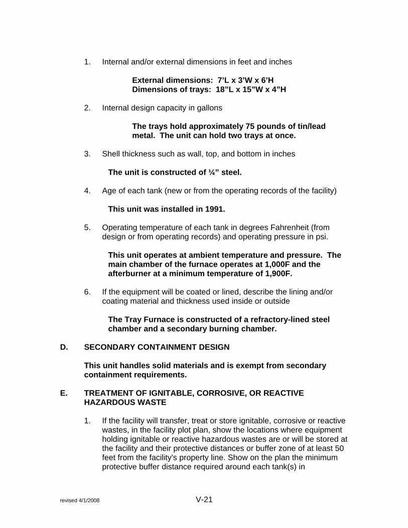
1. Internal and/or external dimensions in feet and inches
External dimensions: 7’L x 3’W x 6’H Dimensions of trays: 18”L x 15”W x 4”H
2. Internal design capacity in gallons
The trays hold approximately 75 pounds of tin/lead metal. The unit can hold two trays at once.
3. Shell thickness such as wall, top, and bottom in inches
The unit is constructed of ¼” steel.
4. Age of each tank (new or from the operating records of the facility) This unit was installed in 1991.
5. Operating temperature of each tank in degrees Fahrenheit (from
design or from operating records) and operating pressure in psi. This unit operates at ambient temperature and pressure. The main chamber of the furnace operates at 1,000F and the afterburner at a minimum temperature of 1,900F.
6. If the equipment will be coated or lined, describe the lining and/or coating material and thickness used inside or outside
The Tray Furnace is constructed of a refractory-lined steel chamber and a secondary burning chamber.
D. SECONDARY CONTAINMENT DESIGN
This unit handles solid materials and is exempt from secondary containment requirements.
E. TREATMENT OF IGNITABLE, CORROSIVE, OR REACTIVE
HAZARDOUS WASTE
1. If the facility will transfer, treat or store ignitable, corrosive or reactive wastes, in the facility plot plan, show the locations where equipment holding ignitable or reactive hazardous wastes are or will be stored at the facility and their protective distances or buffer zone of at least 50 feet from the facility's property line. Show on the plan the minimum protective buffer distance required around each tank(s) in

revised 4/1/2008 V-22
accordance with Table 2-1 through 2-6 of the National Fire Protection Association's "Flammable and Combustible Liquids Code". Data is available from the National Fire Protection Association, 1 Batterypark, Quincy, MA., 02267, Phone: (800) 344-3555.
2. Describe the precautions taken by the facility, e.g. distances of
separation between incompatible wastes and the locations of dikes, berms, or walls used to maintain the separation, to prevent reactions involving ignitable or reactive wastes which would result in any of the following:
The facility does not handle incompatible wastes. This unit does not treat, store, or transfer incompatible, ignitable, reactive or corrosive wastes.
F. SPECIFIED AIR EMISSIONS CONTROLS The waste treated in this unit does not contain volatile organics and is exempt from the provisions of Title 22, Section 66264.1082. The facility does maintain an air permit from the Bay Area Air Quality Management District and the required air emission controls are in place on this equipment. The required control consists of a baghouse for particulate control. G. ENGINEER’S CERTIFICATION OF TANK INTEGRITY AND
SECONDARY CONTAINMENT
If treatment is conducted in tanks or containers please refer to Section IV.G for details on tank integrity engineering certification and secondary containment engineering certification.
H. ENGINEER'S QUALIFICATION
1. Refer to Section IV.H for details of Engineer’s qualifications for certifications.

revised 4/1/2008 V-23
SECTION V – FACILITY DESIGN (TREATMENT) Unit #20—600 Crucible Furnace Unit #21—430 Crucible Furnace
A. TREATMENT PROCESS DESCRIPTION AND FLOW DIAGRAM
1. Treatment process: Describe in detail all of the chemical treatment processes that are or will be done in
Unit #20 (600 Crucible Furnace) and Unit #21 (430 Crucible Furnace) are gas-fired tilt crucible furnaces used to melt samples of printed circuit boards with copper for assay purposes. Unit #22 is not regulated. It is a reverberatory furnace that processes unregulated silver-only sludges and steel wool with silver.
a. Equipment used Silicon carbide crucible is used and lasts approximately 20 melts. Material is manually added to the crucible using a shovel or scoop. b. Chemicals added Fluxing agents are used to improve the quality of metal recovered and to create the slag that contains the impurities. The specific fluxing agents vary depending upon the type of melt, but may include soda ash, sulfur, or lime.
c. Process type (e.g., batch, continuous, etc.) The furnace operates on a batch basis.
d. Feed rate (e.g., gal/min., lb/hr., etc.)
Process rates vary depending upon the material processed; the following are average rates: 600 Furnace: 360 lbs/hr 430 Furnace: 260 lbs/hr
e. Chemical reactions, if any Metal + Metal Compounds + Fluxing Agents Metal + Slag

revised 4/1/2008 V-24
f. Products and by-products for each chemical treatment process Products are metal bars (typically silver, but can be other metals). The by-product is slag.
2. Flow Process Diagram: Include a diagram of existing or planned treatment process unit and associated treatment equipment, including all piping throughout the facility connecting treatment containers, tanks, reactors, vats, etc., showing any valves, plumbing, pumps, process flow direction, etc
In addition, provide the following detailed information, diagrams and drawings for each tank: a. Indicate whether the equipment (e.g. tank) is or will be entirely or
partially above and/or below ground, if applicable. The unit is located above ground. b. Indicate whether the equipment (e.g. tank) can or will be able to
be entered for inspection and routine maintenance, if applicable. This unit is too small to enter for inspection and maintenance, but all parts are readily accessible for inspection and maintenance. c. Show the aisle space between containers, tanks or other
equipment. See attached drawings.
d. If there is or will be an automatic or manual feed waste safety
cutoff system, describe the hazardous waste feed safety cutoff system, if applicable.
Not applicable.
e. If there are or will be tanks that are uncovered and outdoors, minimum freeboard is required. Provide calculations to show that each open uncovered tank has or will have sufficient containment volume to hold the rainfall from a 24-hour, 25-year storm. Rainfall data may be obtained from the Department of Water Resources, Office of the State Meteorologist, Phone: (916) 653-5791.
Not applicable, as this unit is located under the roof.

revised 4/1/2008 V-25
f. If there is or will be a bypass system to a standby tank or a backup plan to prevent overfills, describe this system or the backup plan.
Not applicable.
g. If there are or will be tanks that are airtight, pressurized or under vacuum, describe the pressure control and/or pressure release controls for closed tanks such as vents and relief valves.
This unit operates at ambient pressure.
h. If there are or will be temperature controls used in any tanks,
describe the temperature controls and temperature cutoff safety controls.
The temperature of the furnace is regulated by gas flow. The gas flow can be manually cut off if necessary.
i. If there are or will be liquid level indicators used in tanks, describe
the liquid level measurement devices or indicators. Not applicable.
j. If there are or will be tanks that contain volatile hazardous wastes, describe the pressure relief or tank venting and vapor control systems for these tanks.
None of the wastes are volatile.
k. If there are or will be tanks that are outdoors and made of metal,
describe how each tank is protected from lightning. This unit is not located outdoors.
3. For any treatment unit, furnish sampling data that shows the
effectiveness of the treatment. This data should be based on sampling of untreated incoming hazardous waste and waste after treatment. The samples must be tested at a California state certified analytical laboratory.
4. Provide the following information concerning prevention of releases
to the environment:
a. Describe how the facility does or will prevent any releases of hazardous waste from reaching surface soils, surface water or

revised 4/1/2008 V-26
wetlands. This unit is located indoors on the concrete pad. The materials handled in the unit are solids. Spilled material would solidify instantly. b. Describe how the facility does or will prevent any releases of
hazardous waste from reaching the air. The unit is vented to a baghouse to control particulate emissions.
B. HAZARDOUS WASTES TREATED
1. Provide the name and describe the physical properties of each hazardous waste that is or will be treated in each process. Be sure that the information includes all of the following:
a. Common waste chemical name(s)
Stream Letter Silver Flake L Other metal-bearing sludges (dry) Q Metal dust/machining waste P Off-specification, aged or surplus inorganics N Laboratory chemical waste O
b. EPA and/or California hazardous waste number(s) See Waste Analysis Plan, Section III.
c. Specific gravity Variable, but solids with high metal content
d. Vapor pressure, if applicable Not Applicable
e. Flame point/auto-ignition temperature, if applicable Not applicable
f. pH Not applicable
g. Color Silver or grey

revised 4/1/2008 V-27
C. TREATMENT DEVICE/EQUIPMENT DESCRIPTION
List all equipment to be used in each treatment process, including containers, tanks, reactors, vats, furnaces, etc. Describe the following if they apply to the equipment (excluding DOT-drums); 1. Internal and/or external dimensions in feet and inches
600 Crucible: 24”W x 37”H 430 Crucible: 18”W x 27”H
The crucibles are placed within a refractory-lined steel shell. 2. Internal design capacity in gallons
The size of the furnaces refers to the pounds of aluminum each will hold; the 600 furnace holds 600 pounds of aluminum, etc. Each furnace will hold varying amounts of other materials, based on their density. Each of the crucibles may be filled to within four inches of the top. Volume capacity of the 600 furnace is 24 gallons; volume capacity of the 430 furnace is 16 gallons.
3. Shell thickness such as wall, top, and bottom in inches
The outer steel shell that holds the refractory is approximately ¼” thick.
4. Age of each tank (new or from the operating records of the facility) 600 Furnace was originally installed in 1985. 430 Furnace was originally installed in 1980.
5. Operating temperature of each tank in degrees Fahrenheit (from
design or from operating records) and operating pressure in psi.
The furnaces operate at approximately 1500F – 2000F with a maximum operating temperature of 2400F.
6. If the equipment will be coated or lined, describe the lining and/or
coating material and thickness used inside or outside The silicon carbide crucible rests in a refractory-lined chamber. The refractory is typically 2-3 inches thick.

revised 4/1/2008 V-28
D. SECONDARY CONTAINMENT DESIGN
This unit handles solid materials and is exempt from secondary containment requirements.
E. TREATMENT OF IGNITABLE, CORROSIVE, OR REACTIVE
HAZARDOUS WASTE
1. If the facility will transfer, treat or store ignitable, corrosive or reactive wastes, in the facility plot plan, show the locations where equipment holding ignitable or reactive hazardous wastes are or will be stored at the facility and their protective distances or buffer zone of at least 50 feet from the facility's property line. Show on the plan the minimum protective buffer distance required around each tank(s) in accordance with Table 2-1 through 2-6 of the National Fire Protection Association's "Flammable and Combustible Liquids Code". Data is available from the National Fire Protection Association, 1 Batterypark, Quincy, MA., 02267, Phone: (800) 344-3555.
2. Describe the precautions taken by the facility, e.g. distances of
separation between incompatible wastes and the locations of dikes, berms, or walls used to maintain the separation, to prevent reactions involving ignitable or reactive wastes which would result in any of the following:
The facility does not handle incompatible wastes. This unit does not treat, store, or transfer incompatible, ignitable, reactive or corrosive wastes.
F. SPECIFIED AIR EMISSIONS CONTROLS The wastes treated and stored in these tanks do not contain volatile organics and are exempt from the provisions of Title 22, Section 66264.1082. The facility does maintain an air permit from the Bay Area Air Quality Management District and the required air emission controls are in place on this equipment. The required control consists of a baghouse for particulate control. G. ENGINEER’S CERTIFICATION OF TANK INTEGRITY AND
SECONDARY CONTAINMENT
If treatment is conducted in tanks or containers please refer to Section IV.G for details on tank integrity engineering certification and secondary containment engineering certification.

revised 4/1/2008 V-29
H. ENGINEER'S QUALIFICATION
1. Refer to Section IV.H for details of Engineer’s qualifications for certifications.

Revised 4/1/2008 V-30
SECTION V – FACILITY DESIGN (TREATMENT) Unit #27–E-Waste/Printed Circuit Board Shredder Unit
A. TREATMENT PROCESS DESCRIPTION AND FLOW DIAGRAM
1. Treatment process: Describe in detail all of the chemical treatment processes that are or will be done in
Unit #27 (E-Waste/Printed Circuit Board Shredder) is a two shaft rotary shear shredding unit designed to shred to a specified size electronic scrap and waste, printed circuit boards, or similar materials. The prepared materials can then be beneficially recycled through primary smelters or resource recovery facilities. The permitted portion of the unit is the shredding system and is not the eddy current separation system associated with this unit.
a. Equipment used SSI Shredder, Model 5000H b. Chemicals added None.
c. Process type (e.g., batch, continuous, etc.) The shredder operates on a continuous basis once feeding begins.
d. Feed rate (e.g., gal/min., lb/hr., etc.) 30,000 lbs/hr e. Chemical reactions, if any None.
f. Products and by-products for each chemical treatment process
The product is a shredded scrap. The by-product is baghouse dust.
2. Flow Process Diagram: Include a diagram of existing or planned treatment process unit and associated treatment equipment, including all piping throughout the facility connecting treatment containers, tanks, reactors, vats, etc., showing any valves, plumbing, pumps, process flow direction, etc

Revised 4/1/2008 V-31
In addition, provide the following detailed information, diagrams and drawings for each tank: a. Indicate whether the equipment (e.g. tank) is or will be entirely or
partially above and/or below ground, if applicable. The unit is located above ground. b. Indicate whether the equipment (e.g. tank) can or will be able to
be entered for inspection and routine maintenance, if applicable. This unit can be entered for inspection and maintenance. c. Show the aisle space between containers, tanks or other
equipment. See attached drawings of the facility layout.
d. If there is or will be an automatic or manual feed waste safety
cutoff system, describe the hazardous waste feed safety cutoff system, if applicable.
The shredder is operated by a main control panel on/off switch, which also serves as an emergency off. There are also nine emergency stop buttons located at various points of the system. These nine emergency buttons include those in the eddy current conveyor system, which is not a part of the permitted portion of the unit. Any one of these switches, when activated, stops the entire system.
e. If there are or will be tanks that are uncovered and outdoors, minimum freeboard is required. Provide calculations to show that each open uncovered tank has or will have sufficient containment volume to hold the rainfall from a 24-hour, 25-year storm. Rainfall data may be obtained from the Department of Water Resources, Office of the State Meteorologist, Phone: (916) 653-5791.
Not applicable, as this unit is located under the roof inside the A Warehouse.
f. If there is or will be a bypass system to a standby tank or a
backup plan to prevent overfills, describe this system or the backup plan.
Not applicable.

Revised 4/1/2008 V-32
g. If there are or will be tanks that are airtight, pressurized or under
vacuum, describe the pressure control and/or pressure release controls for closed tanks such as vents and relief valves.
This unit operates at ambient pressure.
h. If there are or will be temperature controls used in any tanks,
describe the temperature controls and temperature cutoff safety controls.
This unit operates at ambient temperature.
i. If there are or will be liquid level indicators used in tanks, describe
the liquid level measurement devices or indicators. Not applicable.
j. If there are or will be tanks that contain volatile hazardous wastes, describe the pressure relief or tank venting and vapor control systems for these tanks.
None of the wastes are volatile.
k. If there are or will be tanks that are outdoors and made of metal,
describe how each tank is protected from lightning. This unit is not located outdoors.
3. For any treatment unit, furnish sampling data that shows the
effectiveness of the treatment. This data should be based on sampling of untreated incoming hazardous waste and waste after treatment. The samples must be tested at a California state certified analytical laboratory.
Not applicable, since the treatment is size reduction and not removal of hazardous constituents. 4. Provide the following information concerning prevention of releases
to the environment:
a. Describe how the facility does or will prevent any releases of hazardous waste from reaching surface soils, surface water or wetlands.
This unit is located indoors on the concrete pad. The materials

Revised 4/1/2008 V-33
handled in the unit are solids. Spilled material can be swept up and does not pose a threat to surface water or soils in the interim. b. Describe how the facility does or will prevent any releases of hazardous waste from reaching the air. The unit is vented to a baghouse to control particulate emissions.
B. HAZARDOUS WASTES TREATED
1. Provide the name and describe the physical properties of each hazardous waste that is or will be treated in each process. Be sure that the information includes all of the following:
a. Common waste chemical name(s)
Stream Letter Miscellaneous residue with silver W Miscellaneous residue with lead X Slag M Electronic scrap BB Computer monitors/CRTs/televisions AA
Note that this unit handles mostly nonhazardous and universal wastes. b. EPA and/or California hazardous waste number(s) See Waste Analysis Plan, Section III.
c. Specific gravity Variable, but solids with high metal content
d. Vapor pressure, if applicable Not Applicable
e. Flame point/auto-ignition temperature, if applicable Not applicable
f. pH Not applicable
g. Color Variable

Revised 4/1/2008 V-34
C. TREATMENT DEVICE/EQUIPMENT DESCRIPTION
List all equipment to be used in each treatment process, including containers, tanks, reactors, vats, furnaces, etc. Describe the following if they apply to the equipment (excluding DOT-drums); 1. Internal and/or external dimensions in feet and inches Shredder hopper is 21’ 8” tall and 8’ 6” across, with a depth of 8’. Shredder unit is 12’ 3” wide, 6’ tall and 8’ deep. 2. Internal design capacity in gallons
Not applicable.
3. Shell thickness such as wall, top, and bottom in inches The steel that constructs the unit is at least ¼” thick.
4. Age of each tank (new or from the operating records of the facility) This unit was installed in June 2007.
5. Operating temperature of each tank in degrees Fahrenheit (from
design or from operating records) and operating pressure in psi. This unit operates at ambient temperature and pressure.
6. If the equipment will be coated or lined, describe the lining and/or coating material and thickness used inside or outside
This unit is not coated or lined. D. SECONDARY CONTAINMENT DESIGN
This unit handles solid materials and is exempt from secondary containment requirements.
E. TREATMENT OF IGNITABLE, CORROSIVE, OR REACTIVE
HAZARDOUS WASTE
1. If the facility will transfer, treat or store ignitable, corrosive or reactive wastes, in the facility plot plan, show the locations where equipment holding ignitable or reactive hazardous wastes are or will be stored at the facility and their protective distances or buffer zone of at least 50 feet from the facility's property line. Show on the plan the minimum

Revised 4/1/2008 V-35
protective buffer distance required around each tank(s) in accordance with Table 2-1 through 2-6 of the National Fire Protection Association's "Flammable and Combustible Liquids Code". Data is available from the National Fire Protection Association, 1 Batterypark, Quincy, MA., 02267, Phone: (800) 344-3555.
2. Describe the precautions taken by the facility, e.g. distances of
separation between incompatible wastes and the locations of dikes, berms, or walls used to maintain the separation, to prevent reactions involving ignitable or reactive wastes which would result in any of the following:
The facility does not handle incompatible wastes. This unit does not treat, store, or transfer incompatible, ignitable, reactive or corrosive wastes.
F. SPECIFIED AIR EMISSIONS CONTROLS The wastes treated and stored in these tanks do not contain volatile organics and are exempt from the provisions of Title 22, Section 66264.1082. The facility does maintain an air permit from the Bay Area Air Quality Management District and the required air emission controls are in place on this equipment. The required control consists of a baghouse for particulate control. G. ENGINEER’S CERTIFICATION OF TANK INTEGRITY AND
SECONDARY CONTAINMENT
If treatment is conducted in tanks or containers please refer to Section IV.G for details on tank integrity engineering certification and secondary containment engineering certification.
H. ENGINEER'S QUALIFICATION
1. Refer to Section IV.H for details of Engineer’s qualifications for certifications.

CONFIDENTIAL—TRADE SECRET INFORMATION
Revised 4/1/2008 V-36
SECTION V – FACILITY DESIGN (TREATMENT) Unit #28–CRT Glass Washing Unit
A. TREATMENT PROCESS DESCRIPTION AND FLOW DIAGRAM
1. Treatment process: Describe in detail all of the chemical treatment processes that are or will be done in
Unit #28 (CRT Glass Washing Unit) is designed to remove the coatings from CRT glass to maximize the recyclability of the leaded and unleaded glass that comprises a cathode ray tube.
a. Equipment used Information removed due to confidential nature. b. Chemicals added Information removed due to confidential nature.
c. Process type (e.g., batch, continuous, etc.) Information removed due to confidential nature.
d. Feed rate (e.g., gal/min., lb/hr., etc.) Information removed due to confidential nature. e. Chemical reactions, if any Information removed due to confidential nature.
e. Products and by-products for each chemical treatment process
Information removed due to confidential nature.
2. Flow Process Diagram: Include a diagram of existing or planned
treatment process unit and associated treatment equipment, including all piping throughout the facility connecting treatment containers, tanks, reactors, vats, etc., showing any valves, plumbing, pumps, process flow direction, etc
In addition, provide the following detailed information, diagrams and drawings for each tank:

CONFIDENTIAL—TRADE SECRET INFORMATION
Revised 4/1/2008 V-37
a. Indicate whether the equipment (e.g. tank) is or will be entirely or partially above and/or below ground, if applicable.
The unit will be located above ground. b. Indicate whether the equipment (e.g. tank) can or will be able to
be entered for inspection and routine maintenance, if applicable. This unit will not be entered for inspection and maintenance, though portions that need to be accessed for maintenance will be readily accessible. c. Show the aisle space between containers, tanks or other
equipment. See attached drawings of the facility layout.
d. If there is or will be an automatic or manual feed waste safety
cutoff system, describe the hazardous waste feed safety cutoff system, if applicable.
Information removed due to confidential nature.
e. If there are or will be tanks that are uncovered and outdoors,
minimum freeboard is required. Provide calculations to show that each open uncovered tank has or will have sufficient containment volume to hold the rainfall from a 24-hour, 25-year storm. Rainfall data may be obtained from the Department of Water Resources, Office of the State Meteorologist, Phone: (916) 653-5791.
Information removed due to confidential nature.
f. If there is or will be a bypass system to a standby tank or a
backup plan to prevent overfills, describe this system or the backup plan.
Information removed due to confidential nature.
g. If there are or will be tanks that are airtight, pressurized or under
vacuum, describe the pressure control and/or pressure release controls for closed tanks such as vents and relief valves.
Information removed due to confidential nature.
h. If there are or will be temperature controls used in any tanks,
describe the temperature controls and temperature cutoff safety
CONFIDENTIAL—TRADE SECRET INFORMATION
Revised 4/1/2008 V-38
controls. Information removed due to confidential nature.
i. If there are or will be liquid level indicators used in tanks, describe
the liquid level measurement devices or indicators.
Information removed due to confidential nature. j. If there are or will be tanks that contain volatile hazardous wastes,
describe the pressure relief or tank venting and vapor control systems for these tanks.
Information removed due to confidential nature.
k. If there are or will be tanks that are outdoors and made of metal,
describe how each tank is protected from lightning. Information removed due to confidential nature.
3. For any treatment unit, furnish sampling data that shows the
effectiveness of the treatment. This data should be based on sampling of untreated incoming hazardous waste and waste after treatment. The samples must be tested at a California state certified analytical laboratory.
Information removed due to confidential nature.
4. Provide the following information concerning prevention of releases
to the environment:
a. Describe how the facility does or will prevent any releases of hazardous waste from reaching surface soils, surface water or wetlands.
Information removed due to confidential nature. b. Describe how the facility does or will prevent any releases of hazardous waste from reaching the air. Information removed due to confidential nature.
B. HAZARDOUS WASTES TREATED
1. Provide the name and describe the physical properties of each hazardous waste that is or will be treated in each process. Be sure

CONFIDENTIAL—TRADE SECRET INFORMATION
Revised 4/1/2008 V-39
that the information includes all of the following:
a. Common waste chemical name(s)
Stream Letter Computer monitors/CRTs/television glass AA
Note: This material is classified as a universal waste. b. EPA and/or California hazardous waste number(s) See Waste Analysis Plan, Section III.
c. Specific gravity Variable, but solids with high metal content
d. Vapor pressure, if applicable Not Applicable
e. Flame point/auto-ignition temperature, if applicable Not applicable
pH Information removed due to confidential nature.
f. Color Variable
C. TREATMENT DEVICE/EQUIPMENT DESCRIPTION
List all equipment to be used in each treatment process, including containers, tanks, reactors, vats, furnaces, etc. Describe the following if they apply to the equipment (excluding DOT-drums); 1. Internal and/or external dimensions in feet and inches
Information removed due to confidential nature. 2. Internal design capacity in gallons
Information removed due to confidential nature.
3. Shell thickness such as wall, top, and bottom in inches
Information removed due to confidential nature.

CONFIDENTIAL—TRADE SECRET INFORMATION
Revised 4/1/2008 V-40
4. Age of each tank (new or from the operating records of the facility)
Information removed due to confidential nature.
5. Operating temperature of each tank in degrees Fahrenheit (from design or from operating records) and operating pressure in psi.
Information removed due to confidential nature.
6. If the equipment will be coated or lined, describe the lining and/or
coating material and thickness used inside or outside
Information removed due to confidential nature. D. SECONDARY CONTAINMENT DESIGN
Information removed due to confidential nature. E. TREATMENT OF IGNITABLE, CORROSIVE, OR REACTIVE
HAZARDOUS WASTE
1. If the facility will transfer, treat or store ignitable, corrosive or reactive wastes, in the facility plot plan, show the locations where equipment holding ignitable or reactive hazardous wastes are or will be stored at the facility and their protective distances or buffer zone of at least 50 feet from the facility's property line. Show on the plan the minimum protective buffer distance required around each tank(s) in accordance with Table 2-1 through 2-6 of the National Fire Protection Association's "Flammable and Combustible Liquids Code". Data is available from the National Fire Protection Association, 1 Batterypark, Quincy, MA., 02267, Phone: (800) 344-3555.
The unit will be located in the D Warehouse, at least fifty feet from the property line. 2. Describe the precautions taken by the facility, e.g. distances of
separation between incompatible wastes and the locations of dikes, berms, or walls used to maintain the separation, to prevent reactions involving ignitable or reactive wastes which would result in any of the following:
This unit will be in a separate building from the other wastes
that are recycled at ECS Refining. Additional information removed due to confidential nature of the treatment process itself.

CONFIDENTIAL—TRADE SECRET INFORMATION
Revised 4/1/2008 V-41
F. SPECIFIED AIR EMISSIONS CONTROLS The wastes treated in this unit will not contain volatile organics and is exempt from the provisions of Title 22, Section 66264.1082. The facility does maintain an air permit from the Bay Area Air Quality Management District and the District will be consulted to determine whether this unit will require any additions to the permit. G. ENGINEER’S CERTIFICATION OF TANK INTEGRITY AND
SECONDARY CONTAINMENT
If treatment is conducted in tanks or containers please refer to Section IV.G for details on tank integrity engineering certification and secondary containment engineering certification.
H. ENGINEER'S QUALIFICATION
1. Refer to Section IV.H for details of Engineer’s qualifications for certifications.
Final engineer certification for this unit is pending installation of the unit.

SECTION VI
TRAINING PLAN

Training Plan revised 4/2/2008 Page 1
ATTACHMENT J
TRAINING PLAN
Training Plan revised 4/2/2008 Page 2
TRAINING PLAN
As required by the California Code of Regulations
Section 66264.16
Revised April 2008

Training Plan revised 4/2/2008 Page 3
I . PURPOSE This training plan is designed to document the training required of employees at ECS Refining, as required by Title 22, California Code of Regulations, Section 66264.16. This document will outline how ECS Refining provides the necessary training to employees that are authorized to handle hazardous wastes, will document the relevant job descriptions for employees handling hazardous and non-hazardous wastes, and will reference other relevant plans and procedures that concern training of employees. Certain elements of the training required for employees are covered by the California Occupational Safety and Health Administration (CalOSHA) regulations, as noted. The training program includes information about general plant safety considerations, chemical hazards present, hazardous materials handling, the control of associated hazards, and emergency response information. Most people realize that hazardous materials can be dangerous to human health and the environment. However, such substances do not represent a threat if they are properly handled. It is the goal of this training program to enable our employees to handle hazardous materials and wastes without endangering their health or the environment.
II. ELEMENTS OF THE TRAINING To accomplish the goals outlined in this training plan, ECS Refining will use a combination of classroom and on-the-job training designed to help the employee do his or her job safely. Appendix I of this training plan contains job descriptions for the specific jobs at ECS Refining which involve handling hazardous or universal wastes or the paperwork associated with tracking hazardous wastes. The elements of the training plan are as follows: Initial Training Initial classroom training is provided to each employee as required by 29 CFR 1910.120 (HAZWOPER) and the analogous CalOSHA regulation. This regulation requires workers at fixed hazardous waste facilities to receive twenty-four hours of initial training to perform their job duties safely. At ECS Refining, the twenty-four hour requirement is met through a combination of classroom and on-the-job training that is designed to notify the employee of potential hazards, to educate the employee about personal protective measures in place, how to safely operate machinery and processing equipment in the facility, how to correctly complete paperwork associated with tracking hazardous waste, and how to appropriately respond to emergency situations that may arise at the facility. Initial training is provided within the first six months of an employee’s date of hire. Employees are not allowed to work in an unsupervised capacity prior to receiving the initial training as required by this training plan.

Training Plan revised 4/2/2008 Page 4
Specific topics covered in the training are as follows: General Safety Initial Training Required Annual Refresher Required Injury and Illness Prevention Plan Yes No Hazard Communication Yes No, only when new hazard Hearing Conservation Program Yes No Emergency Action Plan Yes Yes Forklift Training and Operation Yes No, evaluate every 3 years Training Plan Yes No Safety Meetings and Committee Yes No Electrical Safety Orders Yes No Fire Safety and Extinguisher Use and Care Yes
Yes
Portable Power Tools and Equipment Yes No Hand Tools Yes No Lockout/Tagout Yes No Machinery and Machine Guarding Yes No Personal Protective Equipment Yes No, only if new hazard Respiratory Protection Plan Yes No, only if new hazard Confined Spaces Yes No, only if change Lead Exposure and Protection Yes Yes Universal Waste Regulations CRT Management Yes Yes Universal Waste Handling Yes Yes Universal Waste Electronic Devices Yes Yes Hazardous Waste Regulations
Initial Training Required Annual Training Required
Basic waste characteristics Yes Yes Use of manifest Yes Yes Specifics of ECS facility management Yes Yes Driver Training
Initial Training Required Annual Training Required
Shipping hazardous wastes Yes Required every three years DOT Drug and Alcohol Testing Yes No

Training Plan revised 4/2/2008 Page 5
Uniform Fire Code Regulations
Initial Training Required Annual Training Required
Hazardous Materials Storage Yes No Storage of Flammable Liquids Yes No Emergency Escape and Aisle Spacing Yes No Liquefied Petroleum Gases Yes No Fire Protection Systems and Equipment Yes
No
General Safety Precautions Yes No The topics listed above are covered through a combination of classroom training and on-the-job training as applicable to ensure the employee has the necessary knowledge to conduct his or her job safely. Classroom training is supported by use of a written training manual covering such topics as respirator use, RCRA basics, hazardous waste management, hazard communication, lead toxicology, chemical handling procedures, use of hearing protection equipment, use of protective clothing, use of the uniform hazardous waste manifest, emergency procedures, and other topics as appropriate. Additional specific on-the-job training is given to employees prior to his or her assignment to a new task. This training covers proper use of waste management and processing equipment, emergency shut-off of processing equipment, spill cleanup and response procedures, job-specific hazards, and how to minimize hazards. On-the-job training will also cover the hazardous waste tracking paperwork associated with the job, as applicable. Annual Refresher Training Employees will be given annual refresher training to refresh their knowledge on applicable topics. This training may be given at one time during the year, or may be given in smaller mini-trainings as the need arises. The total amount of annual training will be at least eight hours, in accordance with HAZWOPER requirements. See the Table in Section II above for the subjects that require annual refresher training. Safety Meetings Safety meetings are held for plant employees and supervisors to discuss safety issues that may arise in the plant, to review safe handling and operating procedures, and to provide another training forum. These safety meetings are held quarterly, at a minimum. III. RECORDKEEPING To verify compliance with the measures outlined in this training plan, records are kept of employee training. These include a combination of computerized records and files for each employee. Records kept include the following:

Training Plan revised 4/2/2008 Page 6
• Records of initial training given and the topics covered • Records of any on the job training given to employees • Records of refresher courses given • Record of safety meeting topics covered, suggestions given, and attendees
IV. TRAINER All training provided to employees will be given by qualified personnel who are trained in hazardous waste management and employee health and safety issues. Training is typically conducted by the Shop Supervisor. V. JOB DESCRIPTIONS Each employee handling hazardous or non-hazardous waste is covered by a written job description that describes the position’s hazardous waste management tasks and general tasks. An appendix of this plan describes the names of current employees at ECS Refining and their position. Because specific personnel change over time, this list must be updated to reflect the current workforce. Should the list not be current, refer to the employee’s personnel file for job title information. The job descriptions include the training requirements for each job position.

Training Plan revised 4/2/2008 Page 7
ORGANIZATION TABLE The following organizational table lists job titles covered by this training plan. In accordance with Title 22, Section 66264.16(d), the names of persons filling the following positions at ECS Refining will be maintained on-site. Environmental Health and Safety Manager Environmental Health and Safety Specialist General Manager Administrative Assistant Shop Supervisor Truck Driver Equipment Operator Maintenance Supervisor Repair and Maintenance Specialist Emergency Coordinator CRT/UWED Handlers Unlisted positions are those in which the employee does not work with hazardous materials or wastes at any time. These employees will not work in areas where hazardous materials or wastes are stored or treated.

Training Plan revised 4/2/2008 Page 8
JOB DESCRIPTIONS AND TRAINING REQUIREMENTS The following positions are required for hazardous waste and hazardous materials operations at the facility. Certain personnel may fill more than one job title. In addition to the descriptions for the individual positions, all employees must be made aware that in any position at ECS Refining the employee faces possible exposure to hazardous materials. The chemicals used at ECS Refining to which an employee may be exposed are lead, zinc, copper, silver, and other metal dust, soda ash, borax, oil residue, waste photochemicals, acetylene, and oxygen. For the specific hazards of these chemicals please read the information given in the material safety data sheets (MSDS) for each chemical. The MSDSs are located in the Shop Supervisor's or Environmental Health and Safety office. In order to prevent chemical exposure to its employees, ECS Refining requires all employees to complete a certain amount of training. The type of training required is specific for each job position. No employee will be allowed to work without supervision on tasks involving hazardous materials or hazardous wastes until the initial training program has been completed and the supervisor has observed the employee perform the specific task and has judged the employee to be competent at that task. The employees that work in unlisted positions, such as those that work exclusively in the offices, will receive Hazard Communication training (as applicable to their job position) and the portions of the Emergency Response and Contingency Plan that relate to emergency evacuation and fire drill procedures training only. A copy of the job description and a list of the required training for that position will be given to the employee for review and will also be placed in the employee's personnel file for a permanent record. If the job changes or the employee changes jobs within the company the job description will be updated accordingly.

Training Plan revised 4/2/2008 Page 9
Job Title: Environmental Health and Safety Manager
Job Qualifications; The Environmental Manager must have a degree from an accredited college, including course work or other on-the-job training in environmental management and/or engineering courses, plus two or more years' experience at the management level in an environmental operation, preferably in a hazardous waste treatment setting. The Environmental Health and Safety Manager must be knowledgeable regarding applicable California Health and Safety Codes, CalOSHA regulations, and regulations pertaining to the treatment, storage, and transport of hazardous waste materials. Duties Assigned: 1. General
a. The Environmental Health and Safety Manager is responsible for the overall environmental and safety management of the corporation.
b. The Environmental Health and Safety Manager is also in charge of permit applications and maintenance, environmental reporting, and for the contacts with regulatory agencies needed to develop or negotiate permits and/or agreements.
2. Hazardous waste operations
a. The Environmental Health and Safety Manager is responsible for the update of the DTSC Operation Plan, including the Waste Analysis Plan, and the Training Manual, on an annual, or more frequent basis (if necessary).
b. He or she takes responsibility for the submission of required reports to regulatory agencies, including the DTSC Annual Report (due March 1 each year), and Special Incident Reports.
c. The Environmental Health and Safety Manager is responsible for ensuring documentation of training needs.
d. The Environmental Health and Safety Manager must be familiar with the overall operation of the plant, particularly in reference to hazardous waste reclamation activities. He or she will have received the following training prior to assumption of the above duties, and will receive on-going training as required for performance of the job.
Training requirements; The Environmental Manager will receive training in all sections of the training program.

Training Plan revised 4/2/2008 Page 10
Job Title: Environmental Health and Safety Specialist Job Qualifications: Graduation from an accredited university with a degree in a technical discipline such as engineering, chemistry, or geology, plus two or more years' experience. This person must be familiar with hazardous waste management practices, environmental regulations, and implementation of worker health and safety programs. Duties Assigned: The Environmental Health and Safety Specialist assists the Environmental Health and Safety Manager with the following:
• Ensuring that ECS Refining follows relevant environmental regulations and implements appropriate procedures in order to comply with federal, state, and local regulations
• Developing written procedures and plans for hazardous waste management as required
by law
• Conducting relevant facility inspections
• Assuring facility operating permits are in order and kept up to date
• Implementing the worker training program and maintaining the appropriate records.
• Implementing the facili ty health and safety program and maintaining appropriate records. This includes holding regular safety meetings, conducting industrial hygiene monitoring, and handling the worker's compensation program.
Training Requirements: The Environmental Health and Safety Specialist will receive training in all sections of the training program.

Training Plan revised 4/2/2008 Page 11
Job Title: Administrative Assistant Job Qualifications: High school graduation, general secretarial and typing skills, accuracy and ability to work with numbers, plus two years' experience.
Duties Assigned: 1. General (50% of time): performs general office duties including typing, filing, reception, and answering the telephone. 2. Hazardous waste operations (50% of time):
a. Schedules hazardous and universal waste pick-ups, assist clients with completion of UHWM form. Maintains UHWM files, including preparation of forms by facility and distribution, as appropriate, to generators and DTSC.
b. Maintains files of generator hazardous waste profiles.
c. Performs other duties as required.
d. Will complete the following training prior to assumption of these duties, and will receive
the following on-going training as required for performance of the job. Training Requirements: Hazard Communication Training Emergency Response and Contingency Plan Training Driver Training ("Shipping Hazardous Waste" and "How to Complete a Hazardous Waste Manifest")

Training Plan revised 4/2/2008 Page 12
Job Title: General Manager Job Qualifications: High school graduation plus five or more years' experience in equipment operation and maintenance. Prior supervisory experience is essential. Must be able to speak and read English, have good organizational abilities, be able to delegate assignments, be able to effectively supervise personnel. The General Manager must be knowledgeable and able to implement applicable regulations pertaining to the treatment, storage, and transport of hazardous waste materials. The General Manager is responsible for overall management of the plant, including work assignments, material inventory, incoming and outgoing materials, overseeing the maintenance in the plant, and ensuring relevant inspections are conducted in a timely manner. Duties Assigned: 1. General (75% of time):
a. Supervises all warehouse employees involved in hazardous and non-hazardous waste reclamation activities.
b. Responsible for ensuring on the job training of new or transferred employees has been
completed and for overseeing on-going training for others. c. Familiar with facility emergency procedures; arranges for needed
repairs or replacements of equipment or supplies. 2. Hazardous waste operations (25% of time):
a. Reviews UHWM forms for completion and accuracy; follows up if there is a problem.
b. Conducts field tests as needed of hazardous waste materials received at the
facility, or during processing.
c. The General Manager must be familiar with plant operations particularly in reference to hazardous waste reclamation activities. He will receive on-going training as required for performance of the job, and will have received the following training prior to performing the above duties independently.
Training Requirements: The General Manager will receive training in all sections of the training program, except that he is not required to be a licensed hazardous waste driver. However, he is expected to be trained in DOT shipping and transportation requirements as they apply to transporting hazardous waste.

Training Plan revised 4/2/2008 Page 13
Job Title: Shop Supervisor Job Qualifications: High school graduation plus five or more years' experience in equipment operation and maintenance. Prior supervisory experience is desirable. Must be able to speak and read English, have good organizational abilities, be able to delegate assignments, be able to effectively supervise personnel. The Shop Supervisor must be knowledgeable and able to implement applicable regulations pertaining to the treatment, storage, and transport of hazardous waste materials. Duties Assigned: 1. General (95% of time):
d. Supervises all warehouse employees involved in hazardous and non-hazardous waste reclamation activities.
e. Responsible for on the job training of new or transferred employees and conducting on-
going training for others. f. Familiar with facility emergency procedures; arranges for needed
repairs or replacements of equipment or supplies. 2. Hazardous waste operations (5% of time):
d. Reviews UHWM forms for completion and accuracy; follows up if there is a problem.
e. Conducts field tests as needed of hazardous waste materials received at the
facility, or during processing.
f. The Shop Supervisor must be familiar with plant operations particularly in reference to hazardous waste reclamation activities. He will receive on-going training as required for performance of the job, and will have received the following training prior to performing the above duties independently.
Training Requirements: The Shop Supervisor will receive training in all sections of the training program, except that he is not required to be a licensed hazardous waste driver. However, he is expected to be trained in DOT shipping and transportation requirements as they apply to transporting hazardous waste.

Training Plan revised 4/2/2008 Page 14
Job Title: Truck Driver Job Qualifications: High school graduation plus Class A or B Driver's License, with good driving record. No prior experience required, but must be responsible, display good common sense, be neat in appearance, and be able to relate well to customers and others. The truck driver must be physically able to do the work; able to understand and implement regulatory requirements regarding hazardous waste materials; read and write English; and be able to understand and accurately complete UHWM and other forms as required. Duties Assigned: 1. General (95% of time):
a. Determines daily schedule of customer pick-ups and deliveries and performs both tasks.
b. Supplies customers with empty containers for use in storing materials, to be reclaimed.
c. Responsible for reviewing and completing an accurate UHWM from generators. d. Completes daily truck inspection and makes arrangements for repairs.
2. Hazardous waste operations (5% of time):
a. At pick-up assists the generator in completion of the UHWM form, if necessary.
b. When loading or unloading hazardous waste materials, reviews the UHWM form, checks contents listed on container label, and reconciles information on form with the generator as necessary.
c. The truck driver must be familiar with regulations and procedures related to the storage and treatment of hazardous materials. This employee will receive on-going training as required for performance of the job, and will have received the following training prior to performing the above duties independently.
Training Requirements: The truck drivers will receive training in all sections of the training plan except "Confined Space Entry".

Training Plan revised 4/2/2008 Page 15
Job Title: Equipment Operator Job Qualifications:
No prior experience required, but must be responsible, display good common sense, be able to work with minimal supervision, and be safety conscious. The Equipment Operator must be physically able to do the work; able to understand and implement regulatory requirements regarding hazardous waste materials; read and write English; and be able to operate the equipment used in processing. Duties Assigned: 1. General (note, approximately one-half of time is spent on hazardous waste
reclamation activities and the remainder on non-hazardous processing activities): a. Start up, load, and operate, and monitor equipment. b. Must complete process control cards for materials processed, including materials
added to process, and outcome. c. Shut down equipment. d. Unload reclaimed materials from equipment and load and store in appropriate
containers in designated storage areas. e. Assist in area clean-up.
2. Hazardous waste operations:
a. Follows recommended procedures for the treatment and storage of hazardous waste materials and observes mandated safety requirements.
b. This employee must receive on-going training as required for performance of the job, and will have received the following training prior to performing the above duties independently.
Training Requirements: An Equipment Operator will receive all sections of the training except Driver Training. The Equipment Operator will also receive Forklift Training if they are authorized to operate the forklift.

Training Plan revised 4/2/2008 Page 16
Job Title: CRT or Universal Waste Handler Job Qualifications:
No prior experience required, but must be responsible, display good common sense, be able to work with minimal supervision, and be safety conscious. The CRT or Universal Waste Handler must be physically able to do the work; able to understand and implement regulatory requirements regarding hazardous waste materials; read and write English; and be able to operate the equipment used in processing. Duties Assigned: 1. General:
f. Start up, load, and operate, and monitor equipment. g. Must complete process control logs for materials processed, including materials added
to process, and outcome. h. Shut down equipment. i. Unload reclaimed materials from equipment and load and store in appropriate
containers in designated storage areas. j. Assist in area clean-up.
2. Universal waste operations:
c. Follows recommended procedures for the treatment, storage, and packaging of universal waste materials and observes mandated safety requirements.
d. This employee must receive on-going training as required for performance of the job, and will have received the following training prior to performing the above duties independently.
Training Requirements: A CRT or Universal Waste Handler will receive all training except Driver Training, RCRA Basics, Confined Space Entry, and Hazardous Waste Regulations. The CRT or Universal Waste Handler will also receive Forklift Training if they are authorized to operate the forklift.

Training Plan revised 4/2/2008 Page 17
Job Title: Repair and Maintenance Supervisor Job Qualifications: High School graduate, at least five years' experience performing repair and maintenance activities in a similar environment. Prior supervisory experience is desirable. This person must have mechanical aptitude, be proficient at welding and cutting, have experience with electrical systems, be able to perform troubleshooting and repairs, be responsible, and display good common sense. The Repair and Maintenance Supervisor must be physically able to do the work, to read and write English, and must be familiar with the types of equipment used in this facility, and must be safety conscious. Duties Assigned:
1. General a. Supervises and performs general maintenance tasks throughout the facility. b. Supervises and performs troubleshooting, repairs, and installation of equipment
throughout the facility. c. Supervises and performs construction and welding tasks as required. d. Keeps repair and maintenance records on all equipment and vehicles.
2. Hazardous waste operations a. Responsible for repair and maintenance of the baghouses and solder pot. b. Responsible for repair and maintenance of other equipment associated with
hazardous material use, such as ventilation systems. c. This employee will receive on-going training as required for performance of the
job, and will have received the following training prior to performing the above duties.
d. Keeps repair and maintenance records on all equipment and vehicles. Training Requirements: The Repair and Maintenance Supervisor will receive all training except the specific Driver Training and DOT-specific training.

Training Plan revised 4/2/2008 Page 18
Job Tit le: Repair and Maintenance Specialist Job Qualifications: High school graduate, prior experience is desirable, must have mechanical aptitude, must be proficient at welding and cutting, must have experience with electrical systems and be able to perform troubleshooting and repairs, must be responsible, display good common sense, be able to follow instructions and perform tasks with minimal supervision. The Repair and Maintenance Specialist must be physically able to do the work, able to read and write English, be knowledgeable about equipment used at this type of facility, and be safety conscious. Duties Assigned:
1. General a. Performs general maintenance tasks throughout facility. b. Perform troubleshooting, repairs, and installation of equipment throughout
facility c. Will perform construction and welding tasks as required
2. Hazardous Waste Operations a. Responsible for the repair and maintenance of the baghouses and the solder pot. b. May be responsible for the repair and maintenance of other equipment associated
with hazardous material use, such as ventilation systems, vehicles, etc.. c. This employee will receive on-going training as required for performance of
the job and will have received the following training prior to performing the above duties independently.
Training Requirements: A Repair and Maintenance Specialist will receive all training except the Driver Training.

Training Plan revised 4/2/2008 Page 19
Job Tit le: Emergency Coordinator
Job Qualifications:
High school graduation plus two or more years' experience at ECS Refining or a similar facility. Prior supervisory experience is desirable. Must be able to speak and read English, have good organizational abilities, be able to delegate assignments, be able to effectively supervise personnel, and should be certified in Red Cross First Aid. The Emergency Coordinator must be knowledgeable about all of ECS Refining's operations and have sufficient authority to implement the Emergency Response and Contingency Plan.
Duties Assigned: Please refer to the Emergency Response and Contingency Plan for the specific details and responsibilities of the Emergency Coordinator. The Emergency Coordinator may not delegate any responsibilities to any employee but may direct the employees in the event of an emergency. Training Requirements: The Emergency Coordinator will receive training in all sections of the training program.

Training Plan revised 4/2/2008 Page 20
APPENDIX TO TRAINING PLAN – Training Requirements Matrix
EH
&S
Man
ager
EH
&S
Spec
ialis
t
Gen
eral
Man
ager
Adm
inis
trat
ive
Ass
t.
Shop
Sup
ervi
sor
Tru
ck D
rive
r
Equ
ipm
ent O
pera
tor
Mai
nten
ance
Sup
vr.
Mai
nten
ance
Spe
c.
CR
T/U
WE
D H
ndle
r
Em
erge
ncy
Coo
rd.
Training Topic Injury and Illness Prevention Plan X X X X X X X X X X Hazard Communication X X X X X X X X X X X Hearing Conservation Program X X X X X X X X X X Emergency Action Plan X X X X X X X X X X X Forklift Training and Operation X X X X X X X X X X Training Plan X X X X X X X X X X Safety Meetings and Committee X X X X X X X X X X Electrical Safety Orders X X X X X X X X X X Fire Safety and Extinguisher Use and Care
X X X X X X X X X X
Portable Power Tools and Equipment
X X X X X X X X X X
Hand Tools X X X X X X X X X X Lockout/Tagout X X X X X X X X X X Machinery and Machine Guarding X X X X X X X X X X Personal Protective Equipment X X X X X X X X X X Respiratory Protection Plan X X X X X X X X X X Confined Spaces X X X X X X X X Lead Exposure and Protection X X X X X X X X X X CRT Management X X X X X X X X X X Universal Waste Handling X X X X X X X X X X Universal Waste Electronic Devices X X X X X X X X X X Shipping/manifest hazardous wastes X X X X X X X X X X DOT Drug and Alcohol Testing X X X X X X X X X Hazardous Materials Storage X X X X X X X X X Storage of Flammable Liquids X X X X X X X X X Emergency Escape and Aisle Spacing
X X X X X X X X X
Liquefied Petroleum Gases X X X X X X X X X Fire Protection Systems and Equipment
X X X X X X X X X
General Safety Precautions X X X X X X X X X X Topics marked with an “X” are required for the person(s) filling that job title.

Training Plan revised 4/2/2008 Page 21
APPENDIX II -- List of Applicable Regulatory Citations General Safety CalOSHA or DTSC
Section Federal OSHA or EPA Section
Injury and Illness Prevention Plan 8 CCR 3209, 1509 Not Applicable Hazard Communication 8 CCR 5194 29 CFR 1910.1200 Hearing Conservation Program 8 CCR 5097 29 CFR 1910.95 Emergency Action Plan 8 CCR 3220
22 CCR 66264.18 29 CFR 1910, Subpart E
Forklift Training and Operation 8 CCR 3668 29 CFR 1910.178 Training Plan 8 CCR 3203
22 CCR 66264.16 No direct federal equivalent
Safety Meetings and Committee 8 CCR 3203 No direct federal equivalent Electrical Safety Orders 8 CCR 2299-2974 29 CFR 1910, Subpart S Fire Safety and Extinguisher Use and Care
8 CCR 6151 29 CFR 1910, Subpart L
Portable Power Tools and Equipment 8 CCR 3557 29 CFR 1910, Subpart P Hand Tools 8 CCR 3316 29 CFR 1910, Subpart P Lockout/Tagout 8 CCR 4413 29 CFR 1910.147 Machinery and Machine Guarding 8 CCR 3328 29 CFR 1910, Subpart O Personal Protective Equipment 8 CCR 5194 29 CFR 1910, Subpart I Respiratory Protection Plan 8 CCR 3409 29 CFR 1910.134 Confined Spaces 8 CCR 5157 29 CFR 1910.146 Lead Exposure and Protection 8 CCR 5198 29 CFR 1910.1025 Universal Waste Regulations CRT Management 22 CCR 66260.22-23
22 CCR 66261.9 22 CCR 66268.1-66273.90
No federal equivalent
Universal Waste Handling 22 CCR 66273.1-90 No federal equivalent Universal Waste Electronic Devices 22 CCR 66273.1-90 No federal equivalent Hazardous Waste Regulations
DTSC Section US EPA Section
Basic waste characteristics 22 CCR 66261.20-24 40 CFR 261.20-24 Use of manifest 22 CCR 66262.20-23 40 CFR 262.20-23 Specifics of ECS facility management Varies Varies Driver Training
DTSC Section US DOT Section
Shipping hazardous wastes Not Applicable 49 CFR Part 172 DOT Drug and Alcohol Testing Not Applicable 49 CFR Part 382

Training Plan revised 4/2/2008 Page 22
Uniform Fire Code Regulations
UFC Citation Federal Citation
Hazardous Materials Storage UFC Article 80 Not Applicable Storage of Flammable Liquids UFC Article 79 Not Applicable Emergency Escape and Aisle Spacing UFC Article 12 Not Applicable Liquefied Petroleum Gases UFC Article 82 Not Applicable Fire Protection Systems and Equipment
UFC Article 10 Not Applicable
General Safety Precautions UFC Article 11 Not Applicable

SECTION VII
INSPECTION PLAN

revised 4/1/2008 Inspection Plan - 1
I. INTRODUCTION The purpose of this inspection plan is to delineate the procedures ECS Refining uses to ensure the safe and effective handling of hazardous wastes on-site. The inspection schedule includes a review of waste handling equipment, storage areas, emergency equipment, and safety equipment. The inspections are conducted in a manner and at a frequency to help prevent an unauthorized discharge of hazardous waste or a human health threat, as required by Title 22, Section 66264.15. The inspections are divided into the following sections: waste handling equipment, waste loading/unloading areas, waste storage and accumulation areas, waste monitoring equipment, emergency response equipment, and facility safety devices. Inspection logs and forms are maintained on-site and modified to fit facility operational requirements as needed; therefore, they are not included with this inspection plan but are available on-site. Additional inspections are performed outside the scope of hazardous waste inspections. These include preventive maintenance inspections on equipment, inspections of forklift trucks, inspections of delivery trucks, and fire safety inspections. II. ELEMENTS OF THE INSPECTION PLAN This section provides a brief overview of the scope of daily, weekly and monthly inspections. More specific information regarding the elements to be inspected is included in the applicable inspection forms. Daily Inspections Tank system Facility perimeter fencing Loading and unloading areas Emergency eyewashes/showers Weekly Inspections Container storage areas (aisle space, container integrity, capacity, etc.) Forklift inspection Monthly Inspections Safety equipment Spill control equipment Fire extinguishers Quarterly Inspections Fire sprinkler system

revised 4/1/2008 Inspection Plan - 2
Inspection Schedule
Permitted Unit Description Inspection Items Inspection Frequency General Facility Signs, security, fence Daily Containers (Unit #10, Unit #11a, Unit #11b, Unit #13)
Container conditions, labels, incompatibles
Weekly
Tanks Tank # A, B, 1, 2, 3, C
Overfill controls, corrosion, releases, monitoring and leak detection equipment, secondary containment, free board
Daily
Health and Safety Equipment Eye wash Daily Loading and unloading area Spill, cracks of foundation Daily Emergency Response Equipment Inventory, condition of equipment Monthly Furnaces: Hot Pot (Unit #7), 600 (Unit #20), 430 (Unit #21)
See inspection sheet Monthly
Tray Furnace (Unit #15) See inspection sheet Monthly Evaporator (Unit #3) See inspection sheet Monthly, when in use Tank system See inspection sheet Monthly E-Waste/PCBd Shredder (Unit #27)
See inspection sheet Monthly
CRT Glass Washing Unit (#28) See inspection sheet Monthly Note: The Photochemical Processing Unit (Unit #1) is part of the tank system. III. INSPECTION PROCEDURES IIIa. Daily Inspection The daily inspection is designed to examine daily the most important areas of the facility operation. Inspected daily are the tank system, security measures, eyewashes or emergency showers, and the loading and unloading areas. Tank System
• Ensure all high level switches/alarms are working properly • Examine piping for signs of leaks such as dripping liquid or staining • Examine tanks for any signs of leaks or cracks
Loading and Unloading Areas
• Ensure wastes are stored properly • Examine containers for any signs of leaks • Examine loading dock to ensure no spills have occurred
Security Measures
• Note that the facility alarm system is checked automatically by an internal test on a daily basis. No action is required by ECS personnel
• Walk around perimeter fencing to ensure it remains intact • Ensure facility is posted with proper “Danger” signs

revised 4/1/2008 Inspection Plan - 3
Eyewash/Emergency Showers
• Run water through eyewashes/emergency showers as applicable to ensure proper operation
IIIb. Weekly Hazardous Waste Container Inspection The weekly hazardous waste container inspection is to ensure that ECS Refining is within its permitted capacity to store hazardous wastes, to ensure that all containers of hazardous waste are stored properly in permitted areas with lids and labels intact, and that proper aisle spacing of 24” is maintained. Additional information is available on-site in the inspection forms that are maintained throughout the facility. IIIc. Monthly Safety and Emergency Equipment Inspection On a monthly basis, the facility emergency and safety equipment is inspected to ensure it is available at the designated place and replenished properly. In addition, facility fire extinguishers are examined to ensure they are in place at the prescribed locations, are fully charged, and have been recharged by the fire extinguisher vendor within the past year. Refer to the “Monthly Safety and Emergency Equipment Inspection” sheet (current version available on-site) for additional information. IIId. Monthly Equipment Inspections All equipment on-site is maintained and inspected routinely by the ECS Refining maintenance department. This inspection plan covers those pieces of equipment that process hazardous wastes. Equipment is inspected monthly to ensure it is in safe operating condition and will not malfunction in such a way as to endanger human health and/or the environment. The equipment inspection sheets are available on-site for additional information. Additional inspections that the Maintenance Department performs on equipment that processes non-hazardous wastes are outside the scope of this inspection plan.

SECTION VIII
EMERGENCY RESPONSE AND CONTINGENCY PLAN

EMERGENCY RESPONSE AND CONTINGENCY PLAN
for
ECS Refining 705 Reed Street
Santa Clara, CA 95050
Prepared By:
California Environmental Management Service Company, Inc. 1984 The Alameda, Suite 2 San Jose, California 95126
Revision date: September 2007
Beverly Pester, ECS Refining

revised 1/11/08 Page 2
TABLE OF CONTENTS
I. INTRODUCTION 3
II. EMERGENCY COORDINATOR'S DUTIES 3
III. ON-CALL PROCEDURE FOR EMERGENCY COORDINATOR 7
IV. REPORTING REQUIREMENTS 8
V. COMMUNICATIONS, ALARMS, and ACCESS SYSTEMS 10
VI. EVACUATION PROCEDURES 10
VII. MEASURES TAKEN TO MINIMIZE HAZARDS 12
VIII. FIRE AND EXPLOSION PROCEDURES 13
IX. EARTHQUAKE/UNPREDICTED DISASTER PROCEDURES 14
X. RESPONSE TO CHEMICAL RELEASE 16
XI. SHUTDOWN PROCEDURES 19
XII. EMERGENCY EQUIPMENT INSPECTION PROCEDURES 20
XIII. AMENDMENTS TO THE EMERGENCY RESPONSE PLAN 21
ATTACHMENT 1 22 Emergency Contact List
ATTACHMENT 2 23 Recordable Discharge Log
ATTACHMENT 3 24
Reportable Discharge Log ATTACHMENT 4 27
Facility Emergency Response Equipment List ATTACHMENT 5 28
Facility Evacuation Maps

revised 1/11/08 Page 3
I. INTRODUCTION The purpose of this plan is to minimize hazards to human health or the environment from fires, explosions, or any unplanned sudden or non-sudden releases of hazardous materials. The provisions of this plan must be carried out immediately whenever there is a fire, explosion, release of hazardous materials and/or wastes, earthquake, or any other incident which could threaten human health or the environment. Efforts have been made to inform local emergency response organizations of the activities conducted at ECS Refining, as described below. 1. The Hazardous Materials Management Plan (HMMP), the Emergency Response Plan (ERP), and copies of the Material Safety Data Sheets have been provided to the following:
City of Santa Clara Fire Department 2. A letter of intent to establish formal arrangements and a copy of the Emergency Response and Contingency Plan have been provided to the following:
City of Santa Clara Police Department City of Santa Clara Valley Medical Center County of Santa Clara Health Department Office of Emergency Services (local)
Whenever any of the information changes, the organizations listed above will be sent updated information immediately. See Section X of this plan, entitled Amendment of Emergency Response Plan, for details.
Primary Police and Fire Departments The City of Santa Clara Fire and Police Departments are the designated primary emergency response agencies. II. EMERGENCY COORDINATOR'S DUTIES There is at least one of the designated facility Emergency Coordinators, either on-site, or on call, at all times. The Emergency Coordinators are responsible for the direction and coordination of all emergency measures, as described herein. The Emergency Coordinators are:
Ken Taggart, Primary Steve Ryan, Secondary
Jim Taggart, Primary Back-up Marty Veloz, Secondary Back-up

revised 1/11/08 Page 4
Emergency Coordinators have the authority to direct company resources in the event of an emergency. This includes the authority to evacuate the facility, to utilize and purchase equipment and materials, and to contract with outside services and response agencies including police, fire, and clean-up crews. All of the designated facility Emergency Coordinators are familiar with the following:
* the Emergency Response Plan * the location and characteristics of the hazardous materials * the layout of the facility * the operations and activities of the facility * the location of all records within the facility * the emergency shutdown procedures * a general knowledge of the hazardous waste control laws and how they affect emergency response activities.
This is accomplished by providing a combination of in-house and outside training to the Emergency Coordinators whose duties do not familiarize them with these areas. General Procedures in the Event of an Emergency 1. The Emergency Coordinators' order of priorities in any emergency (actual or imminent) are as follows:
a. Ensure human health and safety b. Safeguard the environment, wildlife, and livestock c. Preserve and prevent damage to property d. Preserve and protect company property.
2. The Emergency Coordinator must notify company personnel as necessary to obtain aid and ensure human safety using the facility alarm and communication procedures. The Emergency Coordinator must always immediately evacuate the area of an emergency or accident if any possibility for further injury exists (see evacuation procedures). The Emergency Coordinator must also notify appropriate emergency response agencies and services, as described in this plan. 3. In the event of an accident involving the release of a hazardous material, the Emergency Coordinator must immediately identify the character, exact source, amount, and extent of the release. 4. The Emergency Coordinator must assess possible hazards to human health and the environment that may result from the emergency or accident. This includes an assessment of any indirect effects, such as would result from the run-off of contaminated solutions. If it is determined that such hazards exist, the Emergency Coordinator must

revised 1/11/08 Page 5
immediately notify any response agencies whose help may be needed and any agencies who are required to be notified as to the nature of the event. (See Reporting Requirements on page 6 for additional details.)
Local Emergency Response:
Emergency number - 911
California Office of Emergency Services - (800) 852-7550 The
reports must include the following information:
• name, address, telephone number of the facility owner/operator • name, address, telephone number of the facility • date, time, and type of incident • name and quantity of material(s) involved • the extent of any injuries • an assessment of actual or potential hazards to human health or the environment where
this is applicable • an estimate of the quantity and disposition of recovered material that resulted from the
incident 5. The Emergency Coordinator must ensure that fires, explosions, and hazardousmaterials and/or waste releases do not occur, recur, or spread. Actions required may include:
a. Shut down of operations b. Containment of hazardous materials c. Shut down of utilities d. Notification of outside emergency response agencies and
services, and/or coordination of the in-house emergency response team.
See Section XI for the location and shut down procedures of utility mains. Employees who work with chemicals are trained in how to stop the flow of materials in their area and how to shut down operations in the event of an emergency. The Emergency Coordinator will direct employees when to shut down and when to start up.
6. The Emergency Coordinator will use facility personnel to contain and cleanup hazardous materials spills only if facility personnel are properly trained and equipped for the characteristics of the incident. If there is any possibility that facility personnel are not adequately trained and equipped to respond to a particular emergency situation, the Emergency Coordinator must call for professional help.
7. In the event of a fire, explosion, or hazardous materials release, the Emergency Coordinator must monitor for leaks, pressure build-ups, gas

revised 1/11/08 Page 6
generation, or rupture in valves, pipes, or other equipment, wherever there is a possibility of these problems occurring. 8. After the emergency is under control, the Emergency Coordinator must:
a. Immediately provide for treating, storing, or disposing of recovered waste, contaminated soil or surface water, or any other material that results from the incident, in accordance with all federal, state, and local regulations.
b. Ensure that no materials which are incompatible with any released materials are
treated, stored, or disposed of, until cleanup procedures are completed.
c. Ensure that all emergency equipment is cleaned or replaced and is fit for use before operations are resumed. See Attachment 3 for the log form used for this purpose.
d. Prior to resuming operations, notify the Fire Department and the Department of Toxic
Substances Control that the facility has accomplished items 8a, 8b, and 8c.
e. Record in the Operating Log and submit a report to the Fire Department, Office of Emergency Services, and to the Department of Toxic Substances Control within 15 days of the incident, which includes the following information:
• Name, address, telephone number of the facility owner/operator. • Name, address, telephone number of the facility. • Date, time and type of incident. • Name and quantity of material(s) involved. • The extent of injuries, if any. • An assessment of actual or potential hazards to human health or the
environment. • An estimate of the quantity and disposition of recovered material that
resulted from the incident (if any).

revised 1/11/08 Page 7
III. On-Call Procedure for the Emergency Coordinator
One of the Emergency Coordinators carries with him at all times a pager so that he may be notified outside of regular business hours. The pager telephone number is posted in the shop supervisor's office and near the warehouse telephone. The on-call schedule is posted monthly in the shop supervisor's office for reference.
Pager Telephone Number: (408) 994-7798
Paginq Procedure
1. Dial the pager telephone
number.
2. Wait for the tone.
3. Enter the telephone number at which you may be reached, followed by the pound sign (#). This only works from a touch tone telephone.
4. To indicate there is an emergency at ECS Refining, enter "705" followed by the pound sign (#) instead of a telephone number.

revised 1/11/08 Page 8
IV. REPORTING REQUIREMENTS Aqency Notification: Please note that the City of Santa Clara Fire Department is the local emergency response agency and they MUST be contacted FIRST in the event of any emergency situation at: 911. In addition, the following agencies must also be notified, as indicated below.
Hazardous Materials and/or Waste Spill -Santa Clara Fire Department - 911 - Office of Emergency Services - (800) 852-7550
Airborne Hazard -BAAQMD - (415) 771-6000 ext. 4979
Groundwater, Storm Drain, or Other Public Water Contamination -Regional Water Quality Control Board - (415) 464-1225 Hazard to a Public Waterway
-National Response Center (U.S. Coast Guard) - (800) 424-8802 Hazard to Wildlife or Its Environment
-Department of Fish & Game - (408) 649-2870 or 911 Discharge to the Sewer System
-San Jose/Santa Clara Water Pollution Control Plant Emergency # -(408) 279-7900
Industrial Related Injury Requiring Hospitalization Cal/OSHA Industrial Relations Division - (408) 277-1260 Hazardous Materials Spill on Public Highway -California
Highway Patrol - 911 or (408) 277-1800 Hazardous Materials Spill on City Streets or County Roads -Santa Clara Police Department - 911
-Santa Clara County Sheriff Department - 911 For All of the Above an incident report as per Section 11.8e is required. Incident reports must contain the following information:
1. Name and phone number of the person reporting. 2. Name and address of the facility. 3. The type of accident. 4. The time of the accident. 5. The extent of any injuries. 6. The type and amount of any chemical(s) involved.
7. The possible hazards to humans and the environment both inside and outside the facility.

revised 1/11/08 Page 9
The Emergency Coordinator who is at the scene of the incident must remain available to aid the responding officials. NOTE: Spills that meet the following REPORTABLE DISCHARGE criteria must be reported to the Fire Department even if they do not pose a threat to human health or the environment:
a. The discharge is not contained in secondary containment or by a rigid above-ground structure until it is cleaned up.
b. It takes longer than 8 hours to clean up. c. It causes a deterioration of the secondary containment or rigid above-ground surface. d. It causes an increase in the hazard of fire or explosion, or produces
flammable or toxic gases. e. The facility personnel are evacuated.
A RECORDABLE DISCHARGE is any discharge which meets all of the following criteria:
a. It is from primary containment to secondary containment or to a rigid above ground surface covering that can contain the discharge until it is cleaned up.
b. The permittee can and does clean up the discharge within eight hours and before it
escapes from the secondary containment or above ground surface covering.
c. It causes no increase in the hazard of fire or explosion, no production of flammable or poisonous gas, and no deterioration of the secondary containment or rigid above ground surface.
Any spill meeting these requirements must be immediately cleaned up and noted in the Recordable Discharge Log. See Attachment 2 for a copy of the Recordable Discharge Log.

revised 1/11/08 Page 10
V. COMMUNICATIONS, ALARMS, and ACCESS SYSTEMS ECS Refining has an alarm for fire and burglary. In the event of a fire or burglary the alarm is tied into a company, Security General Alarm, that will notify the fire or police department automatically. In addition, the facility is equipped with an automatic fire sprinkler system that is also monitored by the alarm company and the local fire department. The communication system consists of telephones located throughout the building and an intercom system. In case of fire or chemical release:
Pull the fire alarm in case of a fire. Yell "Fire" or "Evacuate" to the other persons in the building. Dial 911, if possible from the building or from the neighboring building and explain the
situation to the fire department. All hazardous waste storage and processing activities are controlled indoors, with the exception of Area IIb (Evaporator Area), which is on the exterior of the building but under roof. Access to all areas is provided by roll-up doors and man doors. The roll-up doors are a minimum of 8 feet wide by 10 feet high. Main aisle ways to all areas of the plant are maintained to at least this minimum dimension. Aisle ways in the main storage areas are maintained to allow periodic inspections. VI. EVACUATION PROCEDURES Evacuations are announced by the Emergency Coordinator over the intercom system, or by a fire alarm. When an evacuation is announced, employees are to stop work, shut down equipment as necessary, and go to the closest available exit. All employees must leave the facility and report to the designated assembly area. Do not run. Do not linger in entrance ways or driveways, stay together in the assigned assembly area. Follow these procedures:
1. Stay calm, think, avoid panic and confusion.
2. Stop what you are doing. If there is time, shut off any equipment you are operating. Leave by the nearest outdoor exit if safe. The main evacuation route is through the loading dock gate or the back door near the Plant Supervisor's office. Alternate routes are through the "B" Warehouse gate or through the front office.
3. Do not lock any doors as you leave.
4. In case of an emergency proceed to the nearest exit in a quick but cautious manner.

revised 1/11/08 Page 11
Persons requiring medical attention should be moved out of immediate danger (see Facility Map: evacuations routes and second floor for emergency exits).
5. Do not assist in fire control. Keep out of the way, stay clear of the facility and do not
interfere with emergency operations.
6. Move upwind to the assembly area. This is on Grant Street, just outside the yard gate. If the prevailing wind is not blowing from the north as is typical, the meeting area will be in the direction upwind of the building, along Grant Street. Do not leave the area until directed by an Emergency Coordinator.
7. If it is safe, the Emergency Coordinator(s) will stay behind to shut down plant
operations.
8. Wait for instructions from your Emergency Coordinator. Do not re-enter building unless you are told it is safe by an Emergency Coordinator.
9. The Emergency Coordinator will count all employees at the meeting place to
ensure that no one has been left inside. It is very important that each employee report outside at the assembly area to Emergency Coordinator so that everyone can be accounted for. The Emergency Coordinator is also responsible for ensuring any guests have been accounted for. The Emergency Coordinator will notify employees when it is safe to re-enter the facility. Employees are not to re-enter the facility without approval from the Emergency Coordinator.

revised 1/11/08 Page 12
Evacuation of Neighboring Facilities The Emergency Coordinator will designate personnel to direct the evacuation of neighboring businesses, should this be required. The designee will visit each neighboring business and inform them of the evacuation personally.
VII. MEASURES TAKEN TO MINIMIZE HAZARDS OF HAZARDOUS MATERIALS RELEASES Protection of human health and the environment are the primary goals of this contingency plan. As such, it is necessary to take every available measure to minimize the hazards of hazardous materials releases to the air, soil, or surface water. Releases to Air Unplanned releases to air may occur in any of the following situations • Air pollution control equipment malfunction • Crucible furnace leak
All air pollution control equipment is equipped with alarms. The baghouses on the crucible furnace line and the solder furnace line are equipped with temperature alarms to prevent the bags from burning and causing a release. All baghouses are given an inspection prior to each use to ensure that they are operating properly. Any sign of malfunction (dust escaping from the equipment) is immediately investigated for possible causes and the problem, if any, is fixed. Crucible furnaces are monitored prior to each use to look for cracks and abrasions in the
crucible that may develop holes during use. If a crack is noted, the crucible is changed. If a crucible develops a leak during use, the area is evacuated except for personnel necessary to shut down the operation. Once the operation is shut down, the solidified metal is cleaned up and the crucible replaced. Releases to Soil
ECS Refining is on a site that is completely paved in order to prevent any releases to the soil. All hazardous waste processing and handling occurs indoors, or in an outdoor area covered by a roof and surrounded by a containment berm (Area IIb).
Releases to Surface Water
There are no bodies of surface water near the facility. All hazardous waste processing and handling takes place indoors (or in an outdoor area covered by a roof and surrounded by a containment berm (Area IIb); liquids are handled in bermed areas that are underlain with a polymer liner.

revised 1/11/08 Page 13
VIII. FIRE AND EXPLOSION PROCEDURES
1. Determine if you or anyone else is injured or in immediate danger. Secure yourself from danger. Remove injured persons from any immediate danger.
2. Call for medical assistance if necessary.
3. Contact an Emergency Coordinator.
4. Call the Fire Department at once, tell them that there is, or potentially is, the hazard of a
chemical fire involving lead fumes. This is necessary to ensure that they bring chemical spill response equipment and protective gear.
5. Post someone at entrances to the facility to direct emergency vehicles and to unlock the
gate if necessary.
6. The Emergency Coordinator shall institute response actions as required, including fire fighting, facility evacuation, and shut-down procedures.
7. Do not resume any activities unless the Emergency Coordinator directs you to do so,
or gives you an all clear signal.
8. In the event of a fire or explosion, involving or potentially involving, hazardous materials and/or wastes, the Emergency Coordinators and all response personnel shall be aware of the following potential hazards arising from a fire or explosion involving some or all of the following chemicals in use at ECS Refining. Additional information on potential chemical hazards appears in the Material Safety Data Sheets, and these must be reviewed by response personnel before responding to an emergency!

revised 1/11/08 Page 14
IX. EARTHQUAKE OR OTHER UNPREDICTED DISASTER PROCEDURES
1. The greatest immediate danger is posed by the possibility of being struck by falling objects, falling against a hot object, or being splashed by chemicals. Try to get away from anything that may be able to fall on, burn, or otherwise injure you. Get away from the solder pots and furnaces. If outdoors, stay in the open, away from any trees, structures, power lines, explosion hazards, etc. If indoors, try to get under a desk, table, bench, or in a doorway. Do not try to move during a quake unless it is absolutely necessary.
2. Follow the same procedure as for a Fire or Explosion.
3. Follow the same procedure as for a Chemical Release.
4. Be prepared to shut off the water and gas mains.
5. Be aware that electrical, gas and water lines and mains may be down, broken, and out of order, all of which may constitute hazards.
6. Do not resume any activities unless the Emergency Coordinator directs you to do so, or
otherwise gives an all clear signal. The Emergency Coordinator will direct all post-earthquake response activities, until the all clear signal is given.
7. Immediately after the earthquake has ceased, or as soon there after as possible, the
Emergency Coordinator will direct a post-earthquake inspection, to detect spills, leaks, and other hazardous conditions. Only personnel who have been trained in chemical safety and spill response procedures may perform the post-earthquake inspections. No one will enter an area suspected of having a gas release or structural damage. All personnel will wear the following safety equipment while performing these inspections:
• Goggles or splash shield • Gloves • Boots • Chemically resistant "rainsuit" • Respiratory protection for toxic dust
8. Any chemical spills or leaks discovered during the post-earthquake inspection
must be immediately reported to the Emergency Coordinator who will determine if the spill can be safely contained and collected with available in-house resources, or if an outside spill response contractor must be notified.

revised 1/11/08 Page 15
9. In the event that the post-earthquake inspection reveals signs of a chemical release which is, or may be, imminently hazardous to human health, the Emergency Coordinator must terminate the inspection, ensure that the facility has been evacuated, and contact the Santa Clara Fire Department at 911
10. Facility personnel will follow the procedures specified below when conducting
a post-earthquake inspection:
11. Only trained personnel, who have been specifically authorized by the Emergency Coordinator, may perform a post-earthquake inspection The inspection of this area must involve at least two people to ensure a prompt response in the event of an injury or other emergency situation.
12. Should any significant problems be discovered during the post-earthquake
inspection, the Emergency Coordinator will immediately direct appropriate response activities using in-house or outside professional services as necessary. Additional details on spill containment, collection, and residue disposal appears in the following section, entitled, "Response to Chemical Release".

revised 1/11/08 Page 16
X. RESPONSE TO CHEMICAL RELEASE
1. Remove yourself from immediate danger. If necessary, such as during a release of lead fumes or dust, the Emergency Coordinator will institute EVACUATION PROCEDURES and SHUT DOWN PROCEDURES.
2. If there is a release of lead fumes or dust pull the fire alarm. Yell
"Evacuate" to other persons nearby.
3. If it is safe to do so, remove injured persons from immediate danger.
4. If a spill has occurred follow the SPILL RESPONSE PROCEDURES
5. If there is a release or imminent release to land, water, or air, or if there is a threat to human health, or if there is a spill which is beyond the capability of in-house personnel to safely and quickly clean-up: the Emergency Coordinator will immediately contact the Fire Department for assistance.
6. If there is a release or imminent release to land, water, air, or if there is a threat to human
health the Emergency Coordinator will follow the procedures outlined for proper notification of the authorities, Section II.
Response to Chemical Spills
1. Determine if there are any injuries or if you or anyone else are in immediate danger. Remove injured persons from any further damage. Secure yourself from immediate danger. Call for medical assistance if necessary.
2. If the spill is still in progress, assess if there is anything you can do SAFELY to
prevent more material from escaping into the spill area. At no time shall you perform any function that will jeopardize you or anyone around you.
3. If you have determined it is SAFE:
4. If the spill is from a leaking container, determine the location and extent of the leak.
5. If the spill is from a vessel that has material flowing into it, stop the flow of material
into the vessel as soon as possible.
6. Contact the Santa Clara Fire Department at 911 be sure to tell them that there has been a chemical spill so that they can bring the proper spill response equipment. Also contact an Emergency Coordinator immediately.
7. The Santa Clara Fire Department and/or the Emergency Coordinator shall institute
response actions as required, including spill containment and collection, and facility evacuation and shut-down procedures, as appropriate.
8. Only facility personnel who are properly trained, equipped and authorized by the
Emergency Coordinator or properly trained fire fighters may institute spill containment and clean-up procedures. Do not attempt to handle a spill which

revised 1/11/08 Page 17
involves hazardous materials and/or wastes without authorization from the Emergency Coordinator. Before attempting any spill containment and/or collection operations, review the Material Safety Data Sheets for the material(s) in question!
9. Do not resume activities unless the Emergency Coordinator directs you to do so, or
gives an all clear signal.
10. Chemical spills and/or leaks must be handled in specific manners as described below:
11. For small spills-follow procedures on Material Safety Data Sheet.
12. Large Spills may need outside assistance. Contact the Santa Clara County
Fire Department to access the Santa Clara County Hazardous Materials Response Team.
13. Do not attempt to clean-up any spill that is emitting a hazardous fume or
gas, instead evacuate the area immediately. Follow the chemical release procedures for release to air.
14. The facility Emergency Coordinators are responsible for complying with the
mandated spill reporting and recording requirements, as outlined in the Reporting Requirements, in Section III.
15. After the spill has been contained and collected, the area must be decontaminated.
Follow the decontamination procedures below.
Decontamination Procedures Decontamination is typically performed using a water rinse, but other neutralizing solutions will be more appropriate for certain materials, as indicated in the Material Safety Data Sheets. The decontamination rinses must then be transferred into DOT-approved shipping containers and disposed of at a permitted TSD Facility. The Emergency Coordinator will select the appropriate decontamination and reinstate residue disposal methods, after reviewing the Material Safety Data Sheets and consulting with appropriate regulatory authorities. When you are working with chemicals you must take care to not contaminate any areas outside your work area. This is for worker protection from contamination and will help prevent any chemical reactions with incompatible materials. Any employee or equipment leaving a contaminated area must be decontaminated.

revised 1/11/08 Page 18
If gloves or boots have become contaminated, they must be decontaminated before removal. This means they must be washed thoroughly in a solution set up for this purpose and then rinsed in clean water. Both the wash and rinse waters should be saved for disposal at a permitted facility, if necessary. If your clothing or Tyvek suit has become wetted with chemicals you must remove it immediately and proceed to the shower. If you have been exposed to lead fumes or dust you must also immediately remove your clothing and shower. Remove contaminated clothing cautiously, taking care not to make contact with the outside of the clothing. Place clothing or tyvek suit in a drum for Class One disposal. If you are wearing impermeable clothing it must be decontaminated before removal. Although the Tyvek suits are resistant to chemicals they shall be considered as permeable.

revised 1/11/08 Page 19
XI. SHUTDOWN PROCEDURES
Electrical Shutoff Power outage - Turn off power to the furnaces, solder pots, mills, screeners, and shredder. Turn off all breakers in the panel boxes located across from the offices. Be certain that all equipment is off before turning the breakers back on.
Gas Main Shutoff
Using a large crescent wrench or pliers or the wrench chained to the gas main, turn the gas valve 900 clockwise so that valve is diagonal to pipe. Gas mains are located in the front of the building outside the front door.
Water Main Shutoff
Open the cover. Turn the handle until closed. The main water valve is located in the gravel area in front of the building near the corner of Reed and Grant Streets and is marked "water". The wrench used to close the water main is located in the foyer near the shop supervisor's office.
Welding Gas Shutoff
Be sure to shutoff all welding gasses at the tank during an emergency. Turn valve on tank to the right until it is all the way in the down and closed position.
Other
Check to see that all containers are closed, and all chemicals are safely stored.
NOTE: The shut off locations are shown on the evacuation map.

revised 1/11/08 Page 20
XII. EMERGENCY EQUIPMENT INSPECTION PROCEDURES
Fire Extinguishers Fire extinguishers are certified and refilled by a licensed firm annually, and checked monthly during the monthly inspection.
Eyewash Station The eyewash station is checked daily for performance and cleanliness. The eyewash must be flushed during the inspection to remove any particulate matter.
Alarm System The fire and burglar alarm system performs a self test every 40 seconds when it is armed and a more extensive self test every evening when it is first armed. The system will not arm if it does not pass the self test.
Spill Clean-up and Safety Equipment Spill clean-up equipment is replaced when used and the supply is checked monthly. An inventory will be taken monthly to insure the equipment is replaced when the inventory falls below the minimum quantities.
REPAIR AND REPLACEMENT All equipment is repaired or replaced when necessary. Repairs will only be made by qualified persons, such as the alarm company.

revised 1/11/08 Page 21
XIII. AMENDMENTS TO THE EMERGENCY RESPONSE PLAN
This emergency plan shall be amended whenever: • Applicable regulations are revised. • The plan fails in an emergency. • The facility changes in a way that increases the potential for fires, explosions, or releases
of hazardous materials and/or wastes, or changes the response necessary in an emergency situation.
• The list of Emergency Coordinators changes.
• The list of emergency equipment changes.
• The facility changes in any other way to affect any of the information contained in this
plan. Ken Taggart is responsible for monitoring the need for amendments, making the required changes, and distributing the amended plan and for ensuring that a copy of this plan is maintained at the facility.

revised 1/11/08 Page 22
ATTACHEMNT 1
EMERGENCY CONTACT LIST
In the event of an Emergency, Please Contact the Following:
On Call Emergency Response Pager (408) 994-7798 Primary Emergency Coordinator Ken Taggart, Vice President 14292 Old Wood Road Saratoga, CA 95070
Work: (408) 988-4386 Home: (408) 376-3996 Cell: (408) 472-7226
Secondary Emergency Coordinator Steve Ryan, General Manager 4472 Stonyhaven Way San Jose, CA 95111
Work: (408) 988-4386 Home: (408) 362-1798 Cell: (408) 472-7494
Third Emergency Coordinator Jim Taggart, President 320 Bellevue Court Los Altos, CA 94022
Work: (408) 988-4386 Home: (650) 941-9168 Cell: (408) 472-7522
Fourth Emergency Coordinator Marty Veloz 2666 Merganser Court Los Banos, CA 93635
Work: (408) 988-4386 Home: (209) 829-1595 Cell: (408) 472-7553
IN THE EVENT OF A FIRE OR MEDICAL EMERGENCY, CALL 911
THEN GIVE THE FOILLOWING INFORMATION:
“This is (give your name) at ECS Refining, located at 705 Reed Street in Santa
Clara. The nearest cross street is Grant Street. We have an emergency (specify
type of emergency) – please send help. Someone will be waiting in front of the
building to direct you when you arrive (send someone to do so). Our phone
number is (408) 988-4386.”
FOR ALL OTHER EMERGENCIES (CHEMICAL, ELECTRICAL, OR
OTHER), CONTACT ONE OF THE EMERGENCY COORDINATORS
FIRST AND GET DIRECTIONS FROM THEM.

revised 1/11/08 Page 23
ATTACHMENT 2
RECORDABLE DISCHARGE LOG
ECS Refining 705 Reed Street
Santa Clara, CA 95050 (408) 988-4386
Storage Facility: __________________________________________________________ Time/Date Discharge Discovered:____________________________________________ ________________________________________________________________________ Amount/Type Material Discharged: __________________________________________ ________________________________________________________________________ ________________________________________________________________________ Cause of Discharge:_______________________________________________________ ________________________________________________________________________ ________________________________________________________________________ ________________________________________________________________________ ________________________________________________________________________ Corrective Action: ________________________________________________________ ________________________________________________________________________ ________________________________________________________________________ ________________________________________________________________________ ________________________________________________________________________ ________________________________________________________________________ Time/Date Corrected:______________________________________________________ Method of Disposal:_______________________________________________________ ________________________________________________________________________ ________________________________________________________________________ ________________________________________________________________________ Other Comments: _________________________________________________________ ________________________________________________________________________ ________________________________________________________________________ ________________________________________________________________________ Responsible Officer – Name/Signature/Title: ________________________________________________________________________

revised 1/11/08 Page 24
ATTACHMENT 3
REPORTABLE DISCHARGE REPORT FORM ECS REFINING
705 Reed Street, Santa Clara, CA 95050 (408) 988-4386
1. Date and time of incident: ____________________________________________ 2. Describe incident, include: nature of accident, names and quantities of materials involved, action taken, authorities notified, name of reporter, and date of notification: _________________________________________________________________ _________________________________________________________________ _________________________________________________________________ _________________________________________________________________ _________________________________________________________________ _________________________________________________________________ _________________________________________________________________ _________________________________________________________________ _________________________________________________________________ 3. Injuries, if any. Describe who was injured, extent of injuries, and actions taken: _________________________________________________________________ _________________________________________________________________ _________________________________________________________________ _________________________________________________________________ _________________________________________________________________ _________________________________________________________________ 4. Actual or potential health and/or environmental hazards: _________________________________________________________________ _________________________________________________________________ _________________________________________________________________ _________________________________________________________________ _________________________________________________________________ _________________________________________________________________

revised 1/11/08 Page 25
5. Recovered materials, estimated quantities and dispositions of recovered materials: _________________________________________________________________ _________________________________________________________________ _________________________________________________________________ _________________________________________________________________ _________________________________________________________________ _________________________________________________________________ _________________________________________________________________ _________________________________________________________________ _________________________________________________________________ _________________________________________________________________ _________________________________________________________________ _________________________________________________________________
6. Name/title of person completing form:________________________________________
7. Signature: _________________________________
Date: _________________________________ IMPORTANT: See Reporting Requirements, Section Ill. Emergency Response Plans.
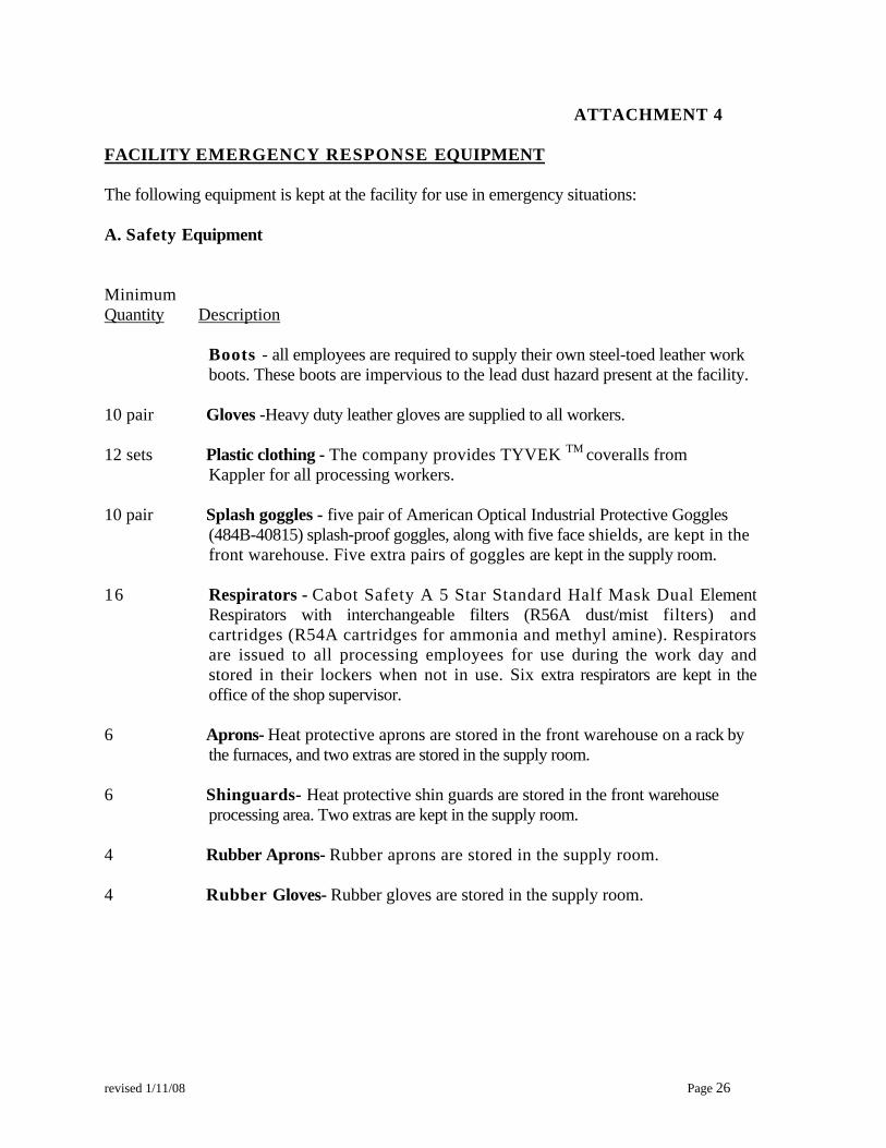
revised 1/11/08 Page 26
ATTACHMENT 4 FACILITY EMERGENCY RESPONSE EQUIPMENT The following equipment is kept at the facility for use in emergency situations:
A. Safety Equipment
Minimum Quantity Description
Boots - all employees are required to supply their own steel-toed leather work boots. These boots are impervious to the lead dust hazard present at the facility.
10 pair Gloves -Heavy duty leather gloves are supplied to all workers. 12 sets Plastic clothing - The company provides TYVEK TM coveralls from
Kappler for all processing workers. 10 pair Splash goggles - five pair of American Optical Industrial Protective Goggles
(484B-40815) splash-proof goggles, along with five face shields, are kept in the front warehouse. Five extra pairs of goggles are kept in the supply room.
16 Respirators - Cabot Safety A 5 Star Standard Half Mask Dual Element
Respirators with interchangeable filters (R56A dust/mist filters) and cartridges (R54A cartridges for ammonia and methyl amine). Respirators are issued to all processing employees for use during the work day and stored in their lockers when not in use. Six extra respirators are kept in the office of the shop supervisor.
6 Aprons- Heat protective aprons are stored in the front warehouse on a rack by
the furnaces, and two extras are stored in the supply room. 6 Shinguards- Heat protective shin guards are stored in the front warehouse
processing area. Two extras are kept in the supply room. 4 Rubber Aprons- Rubber aprons are stored in the supply room. 4 Rubber Gloves- Rubber gloves are stored in the supply room.

revised 1/11/08 Page 27
B. Spill Response Equipment - located in southwest corner on the A warehouse and next to the evaporator (see facility map: Emergency Equipment):
1. Open top drums - 17H - 55 gallon DOT approved. 2. Scoop, shovels and dust pan 3. Large push brooms 4. Floor sweepers are also used to pick up dust from the floors, and to ensure that solder dross
dust is eliminated from the hazardous waste processing area. 5. pH paper 6. Duct tape 7. Hoses 8. Chemical resistant jumpsuit
C. Other Emergency Equipment (see facility map: Emergency Equipment for select locations):
1. Fire Sprinkler System - The entire plant and office are covered by a heat sensitive fire sprinkler system that is alarmed and tied by phone line to the alarm company and the Santa Clara Fire Department.
2. Fire extinguishers - ABC type fire extinguishers and are located throughout the facility.
3. Infra Red Heat Detector Fire/Burglar Alarm will trigger an alarm when a temperature change of
5°F in ten seconds is detected. The alarm is monitored by an alarm company who will notify the authorities and Emergency Coordinator(s) if the alarm goes off.
4. Material Safety Data Sheets on hazardous materials and wastes are retained in the office of
the Production Manager.
5. Emergency eyewash and safety showers are located just outside of the Solder processing room and in the silver processing room. A shower room with six (6) showerheads for personal employee use is located at the entrance to the facility work area. At the end of the work day, all processing workers are required to shower after removing their work clothes and prior to resuming street dress.
6. Telephones for summoning aid are located throughout the facility.
7. First-aid Kit is located in the plant lunch room.
8. Fire Hydrant is located in front of the building.
9. Chemicals: approximately 200 lbs. of sodium bicarbonate used in processing non-hazardous materials is at hand and available for use in fire fighting.
10. Room ventilation
11. Intercom system for notifying emergency evacuation

SECTION VIII
EMERGENCY RESPONSE AND CONTINGENCY PLAN
Evacuation Map
fu!!!:rgency Equipment !&£l!tion Map

lQ!!!.tlDflcr~ip~titO,••O:::;:;;:::=~-==+U~oi~D@'~"~ri~ti~.n>:::=··==1i I IPhotoChemical PTocess.ing 15 Tray Fumace: .Unit{NR) . _.. II 2 Closed Unit J~JShredder A (NR)
3 Vacuum ~orator 17 IClosed Unit4 Closed Unit 18 unit never installed5 DJyin Ovens~_ 19 Unit never installed
. -6 IBall Mills 1 20 600 Cmcible FurnaceI 7 IHotPotFumace 21 430CmcibieFurnace
8 IClosed Unit 22 ReveIbenrto Fumace (NR I9 Closed Unit 23 Drum Wash
I 10 S eAreal 24 !ClOlledUnit ., 1ta Storage Area Ira 25 'Baghouses (regulated by
BAAQMD)lib StorageAreallb__ ' 26 CRTlMonitorShredder )12 jStorage Area m (Nota ! 27 E·WasleIPCBdShredder (NR)I
'h,""",.~ W~~ ,wmgmit ' It3 IStorage Area IV "--I I14 IClosedUnit I NR Notregulated ~
I
II
I
I
I
If--I>:Q
~IIZl
l>:1
~I
50
24'- •
25
Scale in Feet
o
-- - Property line
"...".""=•.~"<~.,,,,,,. Security fence
--LIII
Legend
27'-4'
---- lII
EI
II
II
Warehouse C
WarehouseE
WarehouseB
FACllrTY--BOUN()R'r'---
WarehouseD
----I,,,,,,,,,,
~,
r·1 I,,:3:,,,
,,,,,
_:
- Lni 25
u,~ 00
o c8J 0
FACIlITY LAYOUT - UNIT INVENTORYECS Refining
705 Reed Street
Santa Clara, CA 9S0SU
FACILITY eOUNDRY
Unit 27
Unit 5
l'JDLJ I
UnitllbUnit 23
Non-Hazardous UniversalStorage Area
Unit 15
~-J
!Unit 6/0Unit 7"0 0
I Unit 13 Unit 22-EJ 0 t.Jnit i 2
I Unit21£]g
I Unit20£]-L --l __--:----
arehouse A
STORM DRAIN
\\
\~
\
\\
II
I II
I I'
III
II
I
I I
III
III
tal Igj, Itt;1 IQ I~I I
II
I
I I
III
"--- FACE f ICURB
I
,,-0 I
\\
\
~~.,r;;c~& ~ 'liI!!Jif
________________~~""__ __'________l

U>iCcdiDY1
1.
1-;1. 3
)
1.,31, ;;t
1.,';<1..1.
4jS
Not regulatedNR
I 15 Tray Furnace I16 Shredder A (NR) i
2f IReverberatory Furnace (NR23 iDrwn Wash (NR
, 24 iClosed Unit _
! 25 Bagh~es (regulated byI BAAnMD)
_ _ 17 Closed Unit i18 Unitneverinstatled.__ '19 Unit never installed20 ,600 Crucible Furnace21 430CrocibleFumace
"inY"C "'5nolA:t14 Wtty'ehC4~
nv-e 411 ~L{,;sht(S 1hrv"'i'"oocr-riAc:ltt;!
f4J~vJ()'f,h/~'hower$, ®MSD5s 3/ lo0r5t Aid \LJt (.,
GlovesTvve:il 5ll,itsG0391es~espi rnIv l};"
FtfrDilS$hi \'\8~rctS
\<w"l:Jerfir n>1\S
RI.tI1W alo\lesS?,iUIZt£ 011 se,.R;lUlr~t,
~\\"e 6f'rlvwWS
lIb IStome:e Area lIb i 26 CRTlMonitor Shredder fNR12 !Storage Area III (Not a I 27 E.WasteIPCBdShredder(NR)
ihazardous waste storage unit) I
13 iStomge Area IY14 IClosed Unit
($>
8 Closed Unit9 Closed Unit10 SIOTa2!: Area IlIa Storage Area lIn
UnitlDe~ri donr 1 IPhotochemical ProcessingI IUnit (NR)j 2 Closed Unit
'025
"---
Scale in Feet
o
Legend
Warehouse CWarehouseB
WarehouseD
WarehouseE
----1,,,,,,,,,,
·<;1~, ,,;:: :::.JI,,,,,
,
I,
FACiLITY BOtiNDRY
- Unit 25
EI
I
I
II
c======-=;·"·"·..··"······_·_;=::::======~··_·r-l-
~lJ:=::1===~Iil II I
L--iI
FACIUTY BOUNDRY
Unit 2'7
Non··Hazardous UniversalStorage Area
ynit 15
11 [j [Unit 6 10I
Ih~-i I @nit7'-o 0(j) I U" . " D Unit 12Unit 13 tllt."_" " 0® I UnimO CJI -lUnit 20BI..1- _
I
II I
I
I E
II
I
II
I
I I,
III
III
~I I
~II
IQ I~I I
I
II
I
I I
III
"-- FACE F ICURB
I
_~CS ~ F_A_c_rr_ITY__L::A'::~~:C::'~~Ikfi':":C:~~-::.g:::,T:"INVEN'_____T_O_R_Y .~ _L_"_'~_'___"~ Santa Clara, CA 95050

SECTION IX
CLOSURE PLAN

revised 3/13/2008 IX-1
SECTION IX—CLOSURE PLAN 1.0 Brief Overview of Facility Operations ECS Refining recycles hazardous, non-hazardous, and universal wastes. The general types of hazardous wastes accepted are tin/lead solder dross, tin/lead solder paste and wipes, and photographic waste with silver. Non-hazardous wastes recycled are printed circuit boards and related printed circuit board manufacturing scrap. Universal wastes recycled on-site include cathode ray tubes, computer monitors, television sets, and consumer electronic devices. Fluorescent light tubes and batteries may be handled on a transfer basis but are not recycled on-site. For closure cost estimate purposes, the closure costs to be set aside for final removal of hazardous wastes and hazardous waste processing equipment is separated from the costs set aside for final removal of CRT devices and UWEDs. The estimates for decontamination, sampling, and analysis of the concrete pad and soil underneath the site are included with the hazardous waste portion of the cost estimate, but are assumed to apply to both hazardous and universal waste closure cost estimates. 2.0 Closure Plan Overview The facility closure plan is designed so that in the event of closure, minimal efforts will be required to shut down and maintain the facility. The policy of ECS Refining is to recycle all wastes present in the facility at the time of closure in addition to those wastes that may be generated during closure. This closure plan utilizes treatment followed by land disposal for some process residues so that closure costs will not be underestimated. However, ECS Refining intends to recycle these wastes. Due to the nature and widespread use of these materials, there is no reason to believe that this will not be a viable option at closure time. In addition, ECS Refining may elect to dispose of certain hazardous and universal waste processing equipment in a permitted hazardous waste landfill rather than decontaminate it and sample it for disposal as scrap or reuse. This closure plan intends to close the facility such that there is no residual contamination left at the site. Therefore, the closure performance standard for the soil is background levels of metals processed on-site. However, should this closure performance standard not be attainable at the time of closure, ECS Refining will work with the Department of Toxic Substances Control to establish a risk-based closure performance standard. The concrete pad, structures, and equipment will be decontaminated, if necessary, so that no hazardous waste characteristic is exhibited. Alternatively, ECS Refining may choose to dispose of certain pieces of equipment as hazardous waste rather than decontaminate them at time of closure. In any case, procedures used to close the components will be documented, along with any sampling and analysis conducted as part of the closure activities. 3.0 Closure Timeline

revised 3/13/2008 IX-2
ECS Refining plans to remain open until December 31, 2060. When the decision is made to shut down, the following steps will be taken: (a) The facility operator will notify the DTSC at least 180 days before the intended
hazardous waste facility closure date. (b) Customers will be notified that tin/lead solder dross, photographic chemical waste,
and other residues will no longer be processed on-site as of a specified date at least 120 days before the intended closure date reported to the DTSC, as outlined in item (a) above.
(c) No further material(s) will be accepted for treatment as of the date outlined in item
(b) above. All remaining tin/lead solder dross and photographic chemical waste will be processed on-site or packaged for shipment to an off-site permitted TSDF for reclamation.
(d) Decontamination and sale, or disposal, of all equipment and hazardous materials
will commence. Equipment may also be transferred to another similar facility for similar use. In this case, the decontamination standard will take into consideration the use of the equipment for similar purpose and for similar materials, and the equipment will be decontaminated so that it does not pose a threat to human health or the environment during transport.
(e) ECS Refining will be shut down, in whole or in part, as the result of an emergency
situation, court order, or planned closure. Should the facility be closed or partially shut down, the hazardous waste transfer operations, and the other areas of the facility involving the reclamation of non-hazardous substances, could remain in operation or be gradually phased out. To minimize or eliminate maintenance needs in the event of closure, all hazardous and universal waste residues will be removed. Equipment and structures will be decontaminated, and security measures will be taken. To exclude intruders, the facility will be locked and the intrusion alarm will be activated. 4.0 Prevention of Hazardous Material Release Certain measures will be taken during closure operations, to prevent release of hazardous materials to the atmosphere, ground water, or surface waters. These measures are also designed to protect the general public and the environment from harm. Existing hazardous and universal wastes (off-site generated tin/lead solder dross, tin/lead solder dross with oil residue, other residues, photographic chemical wastes, universal waste electronic devices, and cathode ray tube glass) will be treated on-site, or transferred to another permitted TSD or recycling facility for metal reclamation if that is a viable
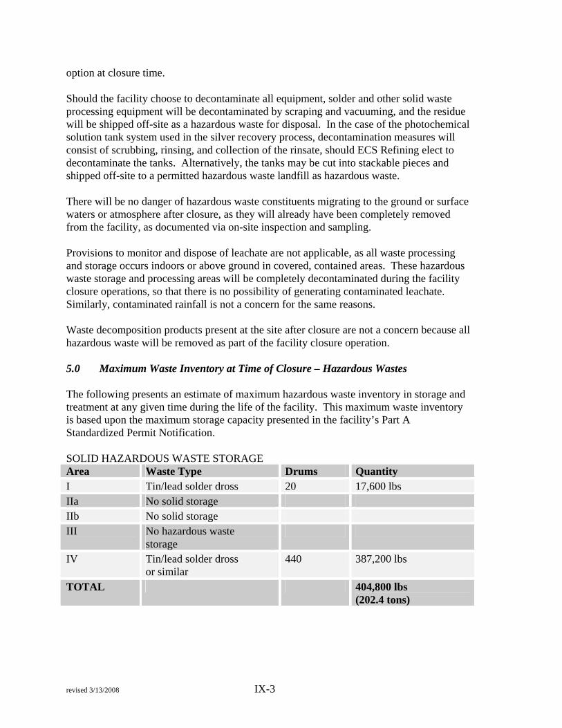
revised 3/13/2008 IX-3
option at closure time. Should the facility choose to decontaminate all equipment, solder and other solid waste processing equipment will be decontaminated by scraping and vacuuming, and the residue will be shipped off-site as a hazardous waste for disposal. In the case of the photochemical solution tank system used in the silver recovery process, decontamination measures will consist of scrubbing, rinsing, and collection of the rinsate, should ECS Refining elect to decontaminate the tanks. Alternatively, the tanks may be cut into stackable pieces and shipped off-site to a permitted hazardous waste landfill as hazardous waste. There will be no danger of hazardous waste constituents migrating to the ground or surface waters or atmosphere after closure, as they will already have been completely removed from the facility, as documented via on-site inspection and sampling. Provisions to monitor and dispose of leachate are not applicable, as all waste processing and storage occurs indoors or above ground in covered, contained areas. These hazardous waste storage and processing areas will be completely decontaminated during the facility closure operations, so that there is no possibility of generating contaminated leachate. Similarly, contaminated rainfall is not a concern for the same reasons. Waste decomposition products present at the site after closure are not a concern because all hazardous waste will be removed as part of the facility closure operation. 5.0 Maximum Waste Inventory at Time of Closure – Hazardous Wastes The following presents an estimate of maximum hazardous waste inventory in storage and treatment at any given time during the life of the facility. This maximum waste inventory is based upon the maximum storage capacity presented in the facility’s Part A Standardized Permit Notification. SOLID HAZARDOUS WASTE STORAGE Area Waste Type Drums Quantity I Tin/lead solder dross 20 17,600 lbs IIa No solid storage IIb No solid storage III No hazardous waste
storage
IV Tin/lead solder dross or similar
440 387,200 lbs
TOTAL 404,800 lbs (202.4 tons)

revised 3/13/2008 IX-4
LIQUID HAZARDOUS WASTE STORAGE Area Waste Type Drums or
Tank Capacity
Quantity (gallons)
I No liquid storage IIa Photochemicals
with silver 20 drums 1,100
IIa Photochemicals with silver
Tank A Tank B
3,000 3,000
IIb Photochemicals with silver
160 drums 8,800
IIb Photochemicals with silver
Tank 1 Tank 2 Tank 3 Tank C
2,500 2,500 2,500 3,200
Area III No hazardous waste storage
Area IV Photochemicals with silver
208 drums 11,440
TOTAL 38,040 gallons Maximum Waste Inventory at Time of Closure – Universal Wastes Area Material Quantity (lbs) I, III, or IV Electronic Devices
(UWEDs) 300,000
Warehouse CRT Glass 400,000 6.0 Decontamination of Facility Equipment This plan provides for removal of the equipment and disposal at a Class I hazardous waste landfill. At the time of closure, the facility may choose to decontaminate and sample the equipment. If the facility chooses to decontaminate, an amended closure plan will be submitted. All facility waste processing and handling equipment can be decontaminated in-house. The tin/lead solder and other solids processing equipment is constructed of stainless steel and the exterior can be decontaminated by vacuuming and wiping, since the waste has not been on these surfaces and they will only be contaminated with airborne dust. The surfaces can then be scraped and then vacuumed with the HEPA filter vacuum or wiped clean. The other components can be pressure washed to assure dust particles are completely removed from the equipment. If this option were implemented, at least two confirmation wipe samples would be taken from each piece of equipment.

revised 3/13/2008 IX-5
If the facility chooses to decontaminate the equipment used to process the liquid waste (the tank system, the reusable columns, the decanting equipment), it will be pressure washed. All wash water will be collected and sampled to determine what the best disposal/recycling alternative for it will be. After all hazardous wastes and equipment have been removed from the facility, the liquid processing areas, loading/unloading area, and liquid storage areas will be pressure washed. To ensure that the concrete has been thoroughly decontaminated, chip samples will be taken according to the provisions outlined in Section 7.0 of this plan. The solid handling areas will be vacuumed with a HEPA filter vacuum and wet wiped to remove any residual dusts. These areas will also be chip sampled according to the sampling plan outlined in the procedures delineated in Section 7.0. The results of the analysis of the concrete chip samples will be used to confirm that no residual contaminants remain on the concrete. Provided that the concrete proves to have no contamination, the Hypalon liners in Areas IIa and IIb will be left intact and, therefore, will not require decontamination. Facility personnel will perform the facility and equipment decontamination using all safety equipment normally worn during operations in the presence of lead dust, including gloves, face shields, and respirators. The facility waste hauling vehicles will be decontaminated, locked, and parked within the building until they can be sold. Since all hazardous wastes transported on the vehicles are placed in closed containers which remain sealed while on the truck, the decontamination of the trucks should be minimal, if required at all. After decontamination is complete, the building will be locked and secured with intrusion alarms connected to a 24-hour infrared sensor. Utilities, except for security lights, will be disconnected or discontinued. All residues generated by the decontamination process, including the steam cleaning and pressure washing rinsate, will be packed in DOT-approved 55-gallon drums and transported off-site by a licensed hazardous waste hauler to a permitted TSD Facility for reclamation or disposal, as appropriate. Alternatively, it will be stored on-site in rented tanks for temporary storage to await removal in bulk. 7.0 Sampling Plan 7.1 Concrete Chip Sampling Plan To ensure that the decontamination of the concrete in the waste storage and processing areas has been complete and that the concrete floor is not contaminated, chip samples will be taken of the concrete. The concrete chip samples will be taken at intervals of one sample for every 250 square feet of concrete floor in the hazardous waste storage and processing areas, or will be biased toward areas that appear to have staining of the concrete, if these areas exist. This includes Storage and Processing Area IIa, Storage and Processing Area IIb, Storage Area III, and the Receiving Area.

revised 3/13/2008 IX-6
Chip samples will be analyzed for the list of 17 regulated California metals and the results compared with hazardous waste classification standards to determine if they are hazardous. 7.2 Soil Sampling Plan During closure of the facility, soil samples must be taken beneath the concrete inside the facility to ensure that no contaminants have migrated through the concrete into the soil below. The areas of the A Warehouse in which ECS Refining handled or stored only solid materials are underlain with a heavy duty polymer liner, so no soil contamination is anticipated. The liquid processing areas are underlain with a Hypalon liner, which is a geotextile commonly used in solid waste landfills. Therefore, no contamination is expected in this soil, either. After the floor decontamination, core soil samples will be collected from the hazardous waste processing areas, the hazardous waste storage areas, and the loading/unloading area. Soil sampling locations will be determined at the time of closure. Samples will be biased toward areas that appear to have the most likelihood of contamination. For example, if there are any large cracks in the concrete through which contaminants may have migrated, then the soil sampling will occur at that location. If there are no areas with evidence of spills or cracks, then samples will be taken at consistent intervals throughout the storage and processing areas. There will be a minimum of 27 soil samples collected at a depth of 6 inches below the concrete. Soil samples will be analyzed for the California list of 17 regulated metals. Selection of analytes for each sample is based upon knowledge of the materials that were processed or stored in the area sampled. Sample locations may need to be altered at time of closure, with approval from the Department of Toxic Substances Control staff, in order to obtain the samples relevant to conditions on site at the time of closure. 8.0 Sampling Quality Assurance and Quality Control Measures In order to assure the validity of the sampling results and data obtained from the samples, standard SW-846 quality control procedures will be followed for all sample collection, preparation, and transport operations. A laboratory certified by the State of California for the applicable analyses will be utilized in all cases. A brief description of the sampling techniques to be employed are as follows: Wipe Sampling: Wipe samples will be taken of surfaces after decontamination. A 12” x 12” square will be marked on the surface to be sampled. A gauze pad will be wetted with the appropriate solvent (slightly acidified water in this case) and swabbed over the entire square. The wipe will then be sealed in a glass jar for transport to the laboratory. Concrete Chip Sampling: The concrete chip samples that will be collected under the provisions of this closure plan will be collected on a 250’ x 250’ grid. A chisel and hammer will be used to obtain a chip at the sampling locations. The chip will be stored in

revised 3/13/2008 IX-7
a glass jar for transport to the laboratory. Soil Sampling: All soil samples taken as part of this closure will be core samples taken beneath the concrete. The concrete cores at each sample depth will be homogenized to obtain a homogeneous sample. The composite soil sample will be thoroughly mixed on-site and the sample split into two glass jars. One of these samples will be sent to the laboratory for analysis and the other retained until the closure has been completed. Duplicate samples will be collected for all samples and will be submitted for analysis for each type of sample at a rate of 10% of the number of samples (one minimum). Other duplicates will be analyzed as needed should data validity be in question. These field duplicates will be sent to the laboratory for analysis; the results will be used to provide a measure of sampling precision. The laboratory will be instructed to prepare and analyze spike samples on our suite of samples at a rate of 10%. The calculated spike recovery data can be used to assess the validity of the analytical results. In addition, the laboratory will perform method blank samples for each type of analysis requested. The total QA/QC analysis scheme, therefore, will result in the number of QA/QC samples analyzed to be 40% of the number of total samples. When sampling equipment is not dedicated but is decontaminated between samples, a sampling method blank will be taken to determine the validity of the decontamination method. This type of sample will be done for the chip sampling and the soil sampling. All of the samples collected under this sampling plan will be labeled with the sample number, date, time, sampler’s name, and the analytes requested. The samples will be preserved according to the procedures outlined in the analytical methods published in SW-846. Samples will be promptly transported to the laboratory to avoid holding time problems, though that is unlikely since these samples will be analyzed for metal contamination. 9.0 Final Closing Schedule In the event of a planned closure, clients will be notified by April 30, 2060, which is 120 days in advance of the intended cut-off date for the acceptance of hazardous wastes, August 31, 2060. In the event of an unplanned closure, receipt of wastes will immediately cease. The anticipated complete planned closure schedule is as follows: (a) Within 60 days after receiving the final shipment of hazardous wastes, which is
October 31, 2060 in an event of a planned closure, ECS Refining will have treated and disposed of all hazardous wastes on the premises.
(b) Within 90 days after receiving the final shipment of hazardous wastes, which is

revised 3/13/2008 IX-8
November 30, 2060 in an event of a planned closure, ECS Refining will have decontaminated the facility equipment and processing areas and the twenty-seven soil samples will have been collected.
(c) Within 120 days after receiving the final shipment of hazardous wastes, which is
December 30, 2060 in an event of a planned closure, but no later than the intended closure date submitted to the DTSC, ECS Refining will have either stored, sold, or disposed of all portable equipment as described above, and completed final arrangements for closure, including final security arrangements. In addition, the soil sampling analysis results should be completed by this time.
10.0 Amendment of Closure Plan This plan will be amended if a significant change in facility operations occurs, and will be reviewed at least annually by the facility operator and updated according to inflation or other significant changes in costs, as required under 22 CCR Section 66264.142. 11.0 Notification to DTSC of Expected Closure Date Once a decision has been made to close the facility, the facility operator is responsible for planning and monitoring the shutdown target dates, in order to ensure notification of the DTSC at least 180 days in advance of the planned closure; this date is June 30, 2060 in an event of a planned closure. The facility operator will also notify the DTSC of any changes in the closure plan as required by the California Code of Regulations, Title 22, Section 66264.112. 12.0 Procedures to Ensure Removal of Hazardous Wastes This section outlines measures which will be taken to ensure that all hazardous wastes are removed from the equipment and the treatment and storage areas. Any tin/lead solder dross, tin/lead solder dross with oil residue, or other tin/lead, or silver residue (including the photographic wastes) on hand will be processed to reclaim the metals if this is a viable option at closure time. The reclaimed solder and silver will be sold for profit. If ECS Refining is unable to process wastes in preparation for closure, they will be transported off-site to an approved reclamation/disposal facility. The closure cost estimate provides funds for this outcome. The hazardous waste processing areas, storage areas, and loading/unloading areas will be thoroughly emptied and then swept with a floor sweeper. The thoroughness of the decontamination effort will be verified by concrete chip sampling and the results of soil sampling from beneath the concrete. All decontaminated equipment will be sold and removed from the facility.

revised 3/13/2008 IX-9
Any contaminated materials present would most likely contain lead dust and other metal particulates resulting in a potential toxicity hazard. The 55-gallon drum containing the final vacuum and equipment and floor decontamination residues will be labeled with the required EPA Hazardous Waste label and transported by a licensed hazardous waste hauler to a permitted off-site TSD Facility. 13.0 Plan to Ensure Remediation of Contaminated Concrete and Soils After the facility equipment decontamination has been completed, any concrete which has been shown to be contaminated by the results of laboratory analysis will be removed and stored in bulk shipping containers, pending disposal at an off-site TSD Facility. In addition to the concrete samples, a total of twenty-seven soil samples will be collected from the hazardous waste loading/unloading, processing, and storage areas, in order to assess soil contamination, if any. Samples will be chosen in areas based upon the most likely areas to be contaminated. For example, samples will be taken in areas with cracks in the concrete slab or staining of the concrete. If no cracks or staining are evident, then samples will be taken at equally spaced intervals throughout the facility. Samples will be taken from each location at soil surface and at a depth of six inches below soil surface, for a total number of 54 samples. The samples will be analyzed for the 17 California regulated metals. Should these analyses reveal contamination levels that exceed hazardous waste criteria, the contaminated materials will be collected, removed, and transported to a permitted TSD Facility for disposal. Following this, additional samples will be collected until the decontamination of the facility can be verified. 14.0 Cleanup Criteria for Soil This closure plan provides a cleanup criteria for removal of any contaminated soil which may be discovered during facility closure through sampling and analysis as outlined in the above discussion. These estimates are solely for planning purposes; ECS Refining intends to consult with DTSC throughout implementation of the closure plan to finalize cleanup levels, if necessary. Because the facility is completely covered in concrete and asphalt, it is not likely that metals contamination will be found underneath. The soil sampling locations have been chosen to be biased towards processing and storage areas with the highest likelihood of showing soil contamination. Results of metal analyses performed on the closure soil samples will be compared to those obtained from the background sample. A background sample will be taken north of the site 1,000 feet; this location is upwind of the facility and, therefore, is not expected to have been impacted by facility operations. As discussed in Section 2.0, a risk-based performance standard for soil will be used if background metal levels are not achievable. This standard will be established in accord with Department of Toxic Substance Control procedures and in consultation with Department staff. Each sample point will be comprised of a core soil sample, as described elsewhere in this plan. All required quality control procedures will be followed, including taking duplicate

revised 3/13/2008 IX-10
samples, and instructing the laboratory to perform method blank and spike samples. At present, there is no known contamination anywhere within or around the facility, and there have been no hazardous waste spills outside of the immediate processing areas. If a hazardous waste spill should occur during the closure clean-up operations, it will be immediately contained and reported to the Regional On-Site Coordinator and the DTSC as described in the facility’s Emergency Response and Contingency Plan. When closure is complete, the facility owner/operator will submit to the DTSC a certification signed by an independent, registered engineer, and by an authorized officer or owner of ECS Refining, certifying that the facility has been closed in accordance with the specifications in the approved closure plan. 15.0 Closure Cost Funding Mechanism and Financial Responsibility Mechanism ECS Refining uses Certificates of Deposit, payable to the Department of Toxic Substances Control, as a closure cost funding mechanism. The currently funded CDs, as of November 2007, are funded for $379,637.60. The closure cost estimate changes periodically due to cost of living updates and/or facility operations. The current closure cost figure is found in an Appendix I of this closure plan. The liability insurance requirements of the financial responsibility requirements are met by ECS Refining by insurance coverage in the required amounts. A copy of the current Certificates of Deposit and Liability Insurance Certificate are included as an attachment to the Standardized Permit Application/Operation Plan.
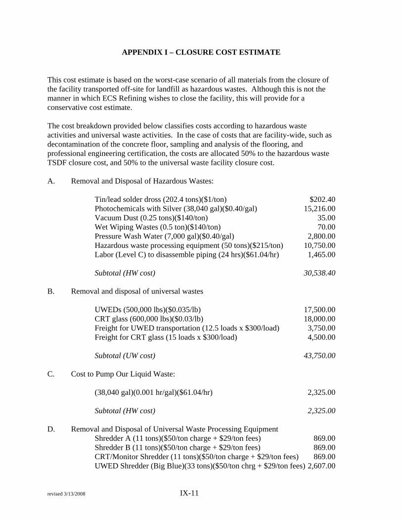
revised 3/13/2008 IX-11
APPENDIX I – CLOSURE COST ESTIMATE
This cost estimate is based on the worst-case scenario of all materials from the closure of the facility transported off-site for landfill as hazardous wastes. Although this is not the manner in which ECS Refining wishes to close the facility, this will provide for a conservative cost estimate. The cost breakdown provided below classifies costs according to hazardous waste activities and universal waste activities. In the case of costs that are facility-wide, such as decontamination of the concrete floor, sampling and analysis of the flooring, and professional engineering certification, the costs are allocated 50% to the hazardous waste TSDF closure cost, and 50% to the universal waste facility closure cost. A. Removal and Disposal of Hazardous Wastes: Tin/lead solder dross (202.4 tons)($1/ton) $202.40 Photochemicals with Silver (38,040 gal)($0.40/gal) 15,216.00 Vacuum Dust (0.25 tons)($140/ton) 35.00 Wet Wiping Wastes (0.5 ton)($140/ton) 70.00 Pressure Wash Water (7,000 gal)($0.40/gal) 2,800.00 Hazardous waste processing equipment (50 tons)($215/ton) 10,750.00 Labor (Level C) to disassemble piping (24 hrs)($61.04/hr) 1,465.00 Subtotal (HW cost) 30,538.40 B. Removal and disposal of universal wastes UWEDs (500,000 lbs)($0.035/lb) 17,500.00 CRT glass (600,000 lbs)($0.03/lb) 18,000.00 Freight for UWED transportation (12.5 loads x $300/load) 3,750.00 Freight for CRT glass (15 loads x $300/load) 4,500.00 Subtotal (UW cost) 43,750.00 C. Cost to Pump Our Liquid Waste: (38,040 gal)(0.001 hr/gal)($61.04/hr) 2,325.00 Subtotal (HW cost) 2,325.00 D. Removal and Disposal of Universal Waste Processing Equipment Shredder A (11 tons)($50/ton charge + $29/ton fees) 869.00 Shredder B (11 tons)($50/ton charge + $29/ton fees) 869.00 CRT/Monitor Shredder (11 tons)($50/ton charge + $29/ton fees) 869.00 UWED Shredder (Big Blue)(33 tons)($50/ton chrg + $29/ton fees) 2,607.00

revised 3/13/2008 IX-12
CRT Glass Washing Unit (10 tons)($50/ton charge + $29/ton fees) 790.00 Labor (Level C) to dismantle (24 hours x $61.04/hr) 1,465.00 Labor to load (5 loads) 1,250.00 Transportation cost ($1,400/load)(5 loads) 7,000.00 Subtotal (UW Cost) 15,719.00 E. Decontamination Costs (22,000 sq. ft.)($0.40/sq. ft.) 8,800.00 Subtotal (HW cost = 50%) 4,400.00 Subtotal (UW cost = 50%) 4,400.00 F. Hazardous Waste Transportation Costs Liquid Hazardous Wastes (10 loads)(8 hr/load)($45/hr) 3,600.00 Solid Hazardous Wastes (10 loads)($1,035/load) 10,350.00 Hazardous waste equipment (3 loads)($1,035/load) 3,105.00 Subtotal (HW cost) 17,055.00 G. Sampling and Analysis (Entire Facility, includes hazardous and universal waste processing areas) Chip Samples 17 CA Metals (62 samples)($395/sample) 24,490.00 Labor to take chip samples (62 x 0.25 hr/sample)($45/hr) 697.50 Soil Samples (54 samples)($395/sample) 21,330.00 Labor to take soil samples (54 samples x 1 hr/smpl)($45/hr) 2,430.00 Subtotal 48,947.50 Subtotal (HW cost = 50%) 24,473.75 Subtotal (UW cost = 50%) 24,473.75 QA/QC Sample Analysis Chip Samples (21 samples)($395/sample) 8,295.00 Soil Samples (11 samples)($395/sample) 4,345.00 Subtotal 12,640.00 Subtotal (HW cost = 50%) 6,320.00 Subtotal (UW cost = 50%) 6,320.00 H. Certification and Engineering Oversight Costs Preparation of Certification and Oversight by P.E. (10% of cost) 18,000.00

revised 3/13/2008 IX-13
Subtotal (HW cost = 50%) 9,000.00 Subtotal (UW cost = 50%) 9,000.00 SUBTOTAL 197,774.90 20% Contingency Factor 39,554.98 ESTIMATED TOTAL COST (March 2008) $237,329.88 COST BREAKDOWN—UNIVERSAL AND HAZARDOUS WASTES Item Hazardous Waste Cost Universal Waste Cost A. Removal and Disposal of Hazardous Wastes
$30,538.40 Not applicable
B. Removal and disposal of universal wastes
Not applicable $43,750.00
C. Removal of Liquid Storage and Processing Tanks and Equipment:
2,325.00 Not applicable
D. Removal and Disposal of Universal Waste Processing Equipment
Not applicable 15,719.00
E. Decontamination Costs
4,400.00 4,400.00
F. Hazardous Waste Transportation Costs
17,055.00 Not applicable
G. Sampling and Analysis QA/QC Samples
24,473.756,320.00
24,473.756,320.00
H. Certification Costs 9,000.00 9,000.00Subtotal 94,112.15 103,662.7520% Contingency Factor 18,822.43 20,732.55TOTAL 112,934.58 124,395.30

SECTION X
CERTIFICATIONS

FACILITY LOCATION, SEISMIC AND PRECIPITATION INFORMATION
I hereby certify the following:
1. I have read and understood Sections 66264.25 and 66270.14(b)(11),Title 22, of the California Code of Regulations on Facility location,Seismic and Precipitation Information.
2. I certify that the nearest fault to my facility is the Hayward Fault and isfive miles away from my facility.
3. I certify that my facility is not in the 100-year flood plain; otherwise Iwill provide the information required under section 66270.14(b)(11 )(0).
4. I understand that this certification is an integral part of the formalapplication for a Standardized Permit for my facility and that anyfalsification is equivalent to a false statement under Health andSafety Code Section 25191 and may be grounds for a permit denial.
James L. Taggart, PresidentPrint Name and Title
ECS Refining705 Reed Street, Santa Clara, CA 95050Facility Address

MANIFEST SYSTEM, RECORD KEEPING AND REPORTING
I hereby certify the following:
1. I have read and understood sections 66264.70 through 66264.78,Title 22, of the California Code of Regulations on Manifest System,Record Keeping and Reporting requirements. I will have or prepare,for my facility, the required records and reports to be in compliancewith all applicable regulations.
2. I certify that a copy of the required records or reports will bemaintained at my facility and will be available to local, state or federalagencies upon request. I understand that this certification is anintegral part of the formal application for a standardized permit for myfacility. And that any falsification is equivalent to a false statementunder Health and Safety Code section 25191 and may be groundsfor a permit denial.
3. My facility is an offsite facility. I have sent a notice to generators thatmay use my facility's services and I have the appropriate permit(s)(section 66264.12(b)). A copy of my notice is kept in my facility.
James L. Taggart, PresidentPrint Name and Title
ECS Refining705 Reed Street Santa Clara, CA 95050Facility Name and Address

PREPAREDNESS AND PREVENTION
I hereby certify the following:
1. I have read and understood Sections 66264.30 through66264.35, 66264.37,and 66270.14(b)(8)and(b)(9), Title 22 of theCalifornia Code of Regulations (Preparedness and Prevention).
2. The procedures and equipment for my facility will be incompliance with these regulations. My facility will be designed,constructed, maintained and operated to minimize the possibility ofa fire, explosion, or any unplanned sudden or non-sudden releaseof hazardous waste or hazardous waste constitutes to air, soil, orsurface water which could threaten human health or theenvironment.
3. I understand that this certification is an integral part of the formalapplication for a Standardized Permit for my facility and that anyfalsification is equivalent to a false statement under Health andSafety Code Section 25191 and may be grounds for a permitdenial.
James L. Taggart, PresidentPrint Name and Title
!
ECS Refining705 Reed StreetSanta Clara, CA 95050Facility Name and Address

SECURITY
I hereby certify the following:
1. I have read and understood Sections 66264.14, and 66270.14(b)(4),Title 22 of the California Code of Regulations (Security).
2. The security procedures and equipment for my facility will be incompliance with these regulations.
3. I understand that this certification is an integral part of the formalapplication for a Standardized Permit for my facility and that anyfalsification is equivalent to a false statement under Health andSafety Code Section 25191 and may be grounds for a permit denial.
, .~-
Aet1/1~flt 7/16tA/4TPrinted Name
ECS Refining705 Reed StreetSanta Clara, CA 95050Facility Add ress
SECTION XI
FINANCIAL RESPONSIBILITY FOR STANDARDIZEDPERMIT FACILITIES

Client#· 41530 ECSREFI
I ACORDTM CERTIFICATE OF LIABILITY INSURANCE I DATE (MMIDDIYYYY)
11/03/05:'RODUCER THIS CERTIFICATE IS ISSUED AS A MATTER OF INFORMATIONGeneral Business Unit ONLY AND CONFERS NO RIGHTS UPON THE CERTIFICATE
ABO Insurance & Financial ServicesHOLDER. THIS CERTIFICATE DOES NOT AMEND, EXTEND ORALTER THE COVERAGE AFFORDED BY THE POLICIES BELOW.
305 Walnut StreetRedwood City, CA 94063 INSURERS AFFORDING COVERAGE NAIC#INSURED INSURER A: American IntI. Specialty Lines Ins.
ECS RefiningINSURER B: Commerce and Industry Insurance Comp
705 Reed StreetINSURER C: Liberty Mutual Company
Santa Clara, CA 95050INSURERD:
INSURERE:
COVERAGESTHE POLICIES OF INSURANCE LISTED BELOW HAVE BEEN ISSUED TO THE INSURED NAMED ABOVE FOR THE POLICY PERIOD INDICATED. NOTWITHSTANDINGANY REQUIREMENT, TERM OR CONDITION OF ANY CONTRACT OR OTHER DOCUMENT WITH RESPECT TO WHICH THIS CERTIFICATE MAY BE ISSUED ORMAY PERTAIN, THE INSURANCE AFFORDED BY THE POLICIES DESCRIBED HEREIN IS SUBJECT TO ALL THE TERMS, EXCLUSIONS AND CONDITIONS OF SUCHPOLICIES. AGGREGATE LIMITS SHOWN MAY HAVE BEEN REDUCED BY PAID CLAIMS.
LTR NSR TYPE OF INSURANCE POLICY NUMBER PJ>.k~~~ri~~J8~1 Pg~~lr~':,b~~N LIMITS
A ~NERAL LIABILITY EG3779045 11/01/05 11/01/06 EACH OCCURRENCE $1.000.000
~ ==rMERCIAL GENERAL LIABILITY ~AMAGE TO ~~~~~~nr~l $100000
I--CLAIMS MADE [!J OCCUR MED EXP (Anyone person) $10000
I--PERSONAL & ADV INJURY $1000000
I--GENERAL AGGREGATE $2000.000
GEN'L AGGREGATE LIMIT APPLIES PER: PRODUCTS - COMP/OP AGG $2000000n POLICY n :;~gT Ixl LOC
B ~TOMOBILE LIABILITY CA3778017 11/01/05 11/01/06 COMBINED SINGLE LIMIT
~ ANY AUTO (Ea accident) $1,000,000
I--ALL OWNED AUTOS BODILY INJURY
(Per person) $SCHEDULED AUTOS
I--
~ HIRED AUTOS BODILY INJURY $~ NON-OWNED AUTOS (Per accident)
~ Comp $1,000 Oed PROPERTY DAMAGEX Coli $1,000 Oed (Per accident) $
GARAGE LIABILITY AUTO ONLY - EA ACCIDENT $==j ANY AUTO OTHER THAN EAACC $AUTO ONLY: AGG $
A EXCESSIUMBRELLA LIABILITY EGU3779046 11/01/05 11/01/06 EACH OCCURRENCE $5000000~ OCCUR D CLAIMS MADE AGGREGATE $5000000
$
~ DEDUCTIBLE $X RETENTION $10000 $
B WORKERS COMPENSATION AND WC4193244 11/01/05 11/01/06 X I T~gvST,~W;, I IOJ~-EMPLOYERS' LIABILITY
$1,000,000ANY PROPRIETOR/PARTNER/EXECUTIVE E.L. EACH ACCIDENT
OFFICERIMEMBER EXCLUDED? E.L. DISEASE - EA EMPLOYEE $1,000,000~~E'i:I~Ls~~oJts16~s below E.L. DISEASE - POLICY LIMIT $1,000,000
A OTHER Pollution EG3779045 11/01/05 11/01/06 $1,000,000 Ea. IncidentA Excess Pollution EGU3779046 11/01/05 11/01/06 $1,000,000 Ea. IncidentC Personal PropertY YU2L9L512139035 11/01/05 11/01/06 $9,558,000 Blld LimitDESCRIPTION OF OPERATIONS / LOCATIONS / VEHICLES / EXCLUSIONS ADDED BY ENDORSEMENT / SPECIAL PROVISIONS
CERTIFICATE HOLDER CANCELLATION T..n n"v Nnti,.,.. fnr Nnn. ofSHOULD ANY OF THE ABOVE DESCRIBED POLICIES BE CANCELLED BEFORE THE EXPIRATION
Evidence of Insurance DATE THEREOF, THE ISSUING INSURER WILL ENDEAVOR TO MAIL --30.- DAYS WRITTEN
Insured Copy NOTICE TO THE CERTIFICATE HOLDER NAMED TO THE LEFT, BUT FAILURE TO DO SO SHALL
IMPOSE NO OBLIGATION OR LIABILITY OF ANY KIND UPON THE INSURER, ITS AGENTS OR
REPRESENTATIVES.
AU~ZED REPRE,TATIVE l.n ,. -1- ~ --
ACORD 25 (2001/08) 1 of 2 #734385 ECSREFI 7LU @ ACORD CORPORATION 1988

IMPORTANT
If the certificate holder is an ADDITIONAL INSURED, the policy(ies) must be endorsed. A statementon this certificate does not confer rights to the certificate holder in lieu of such endorsement(s).
If SUBROGATION IS WAIVED, subject to the terms and conditions of the policy, certain policies mayrequire an endorsement. A statement on this certificate does not confer rights to the certificateholder in lieu of such endorsement(s).
DISCLAIMER
The Certificate of Insurance on the reverse side of this form does not constitute a contract betweenthe issuing insurer(s), authorized representative or producer, and the certificate holder, nor does itaffirmatively or negatively amend, extend or alter the coverage afforded by the policies listed thereon.
ACORD 25-5 (2001/08) 2 of 2 #734385

BANCO POPULAR NORTH AMERICAPO BOX 2057SANFORD FL 32772-2057
E C S REFINItlGASSIGNED STATE OF CALIFORNIADEPT OF TOXIC SUBSTANCE CONTROL705 REED STSANTA CLARA CA 95050
ACCOUNT NUMBER: 8939583954BUSINESS CD
FOR PERSONAL ASSISTANCE CALL:1-800-377-0800
1 R_E_N_E_w_A_l_N_o_T_'c_E lYOUR TIME DEPOSIT HAS BEEN RENEWED AT THERATE BELOW AS OF 07-06-06.
_._".._--
ACCOUNT NUMBERCURRENT INTEREST RATETERMRENEWAL DATENEXT MATURITYREIlEWAL AMOUNT
893958395(,4.641
12 MONTHS07-06-0607-06-07
67,028.06

QJrnenCj\Comerica Bank-California
ASSIGNMENT OF TIME DEPOSIT AGREEMENT
OF TOXIC SUBSTANCES CONTROL
I amlWe are the owner(s) of the following Time Deposit account at Comerica Bank-California.
AccountName ALL METALS, INC DBA ECS REFINING866750000007206
Time Deposit Account,Number ---:;::-- _
Present Balance of Account $ __$_2_78-:...,9_0_2_,_8_4 _
Assignee Name STATE OF CALIFORNIA DEPT
I hereby grant, transfer and assign this account and all rights in connection therewith to the Assignee for a good and valuable i
consideration, receipt of which is hereby acknowledged, for the purpose described as follows:
ASSIGNED TO STATE OF CALIFORNIA DEPT OF TOXIC SUBSTANCES CONTROL
I have physically delivered a duplicate of this Assignment to said assignee.
I understand that the Assignee can withdraw from this account any time on the Assignee's signature alone. I also understand I
that I may not withdraw from this account unless I present Assignee's signed release of Assignment. The Bank assumes nolresponsibility for the condlJct of tlJ.e Assignee and may act on the signature of the Assignee withou urther inquiry. I
:::~::dH:~d.r: ~6'6R~ i/;/5 ~;A office ofBank. •
Print Name ra
Date _0"""'--,9tf--/-=--¥.:...L.9/<_0--,--(;__
BANK ACKNOWLEDGMENT
Authorized Bank epresentative SignatureDate
Bank affirms that there are no other holds on this account, that monies are available, and that the above described assignmenlhas been noted on the Records of said Bank.
CIC\ \l_$\,--v..w...~)__
\ -\
INSTRUCTIONS TO ASSIGNEE
Please sign below for signature identifications and as acknowledgment of your notice of Assignment. Return this Assignment tdthe Bank. In acting on the signature of the Assignee, the Bank assumes no responsibility for the conduct of the Account Holder~
Retain one copy of this Assignment for your files.
Assignee: -'--Print Name Signature
Date _
RELEASE BY ASSIGNEE
Said Assignee hereby releases and relinquishes all rights, title and interest in the account described above.
Date _By -----------------------t
Assignee's Signature
CAOPS 518 (6/98) - 25/Pkg