Embed Size (px)
Citation preview
TITLE: 5X800 MW YADADRI THERMAL POWER
STATION
SPECIFICATION NO. PE-TS-417-155A-A001 SECTION : II
TECHNICAL SPECIFICATION FOR CONDENSATE POLISHING UNIT
SUB-SECTION : IIC REV. NO. 00 DATE :
SECTION – II
GENERAL TECHNICAL REQUIREMENTS
SUB-SECTION IIC - GENERAL TECHNICAL REQUIREMENTS (C&I)
THIS IS A PART OF TECHNICAL SPECIFICATION NO. PE-TS-417-155A-A001
Page 549 of 663
Technical specification for CONTROL & INSTRUMENTATION
5x800 MW YADADRI TPS, NALGONDA
SPEC NO.: PE-TS-417-145-I
VOLUME
SECTION
REV. NO. 00 DATE : 16.08.2018
SHEET OF
FO
RM
NO
. PE
M-6
666
-0
C&I SPECIFICATION
FOR CONDENSATE POLISHING SYSTEM
THIS IS A PART OF TECHNICAL SPECIFICATION NO. PE-TS-417-155A-A001
Page 550 of 663

Technical specification forCONTROL & INSTRUMENTATION
5x800 MW YADADRI TPS, NALGONDA
SPEC NO.: PE-TS-417-145-I
VOLUME
SECTION
REV. NO. 00 DATE : 03.04.2018
SHEET OF
FOR
M N
O. P
EM
-666
6-0
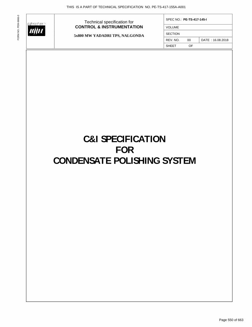
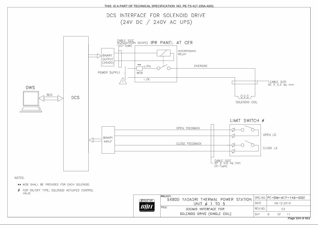
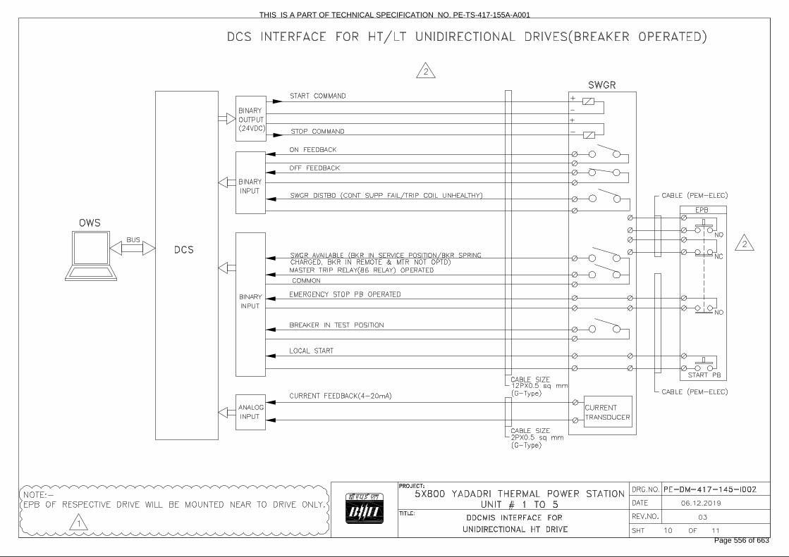
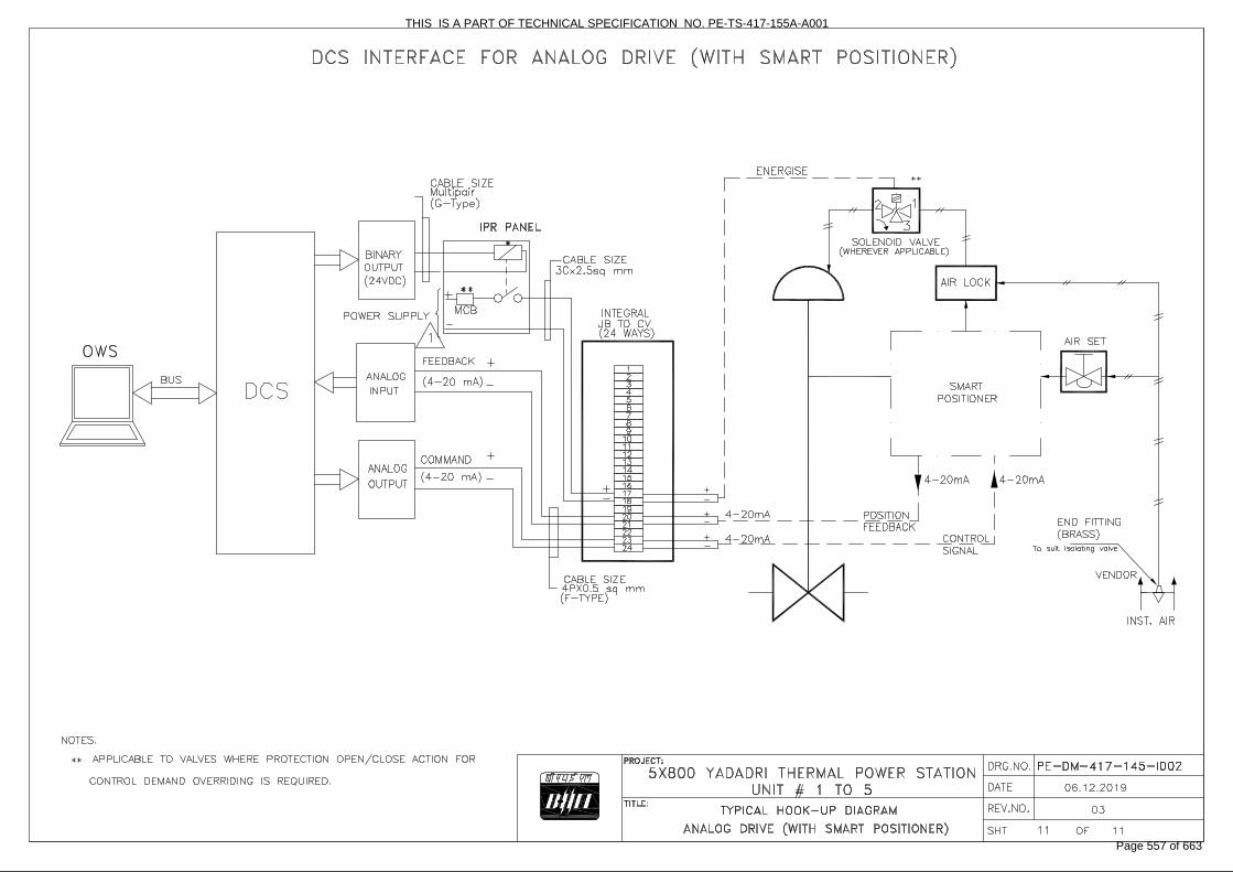
Drive Control Philosophy
THIS IS A PART OF TECHNICAL SPECIFICATION NO. PE-TS-417-155A-A001
Page 551 of 663
THIS IS A PART OF TECHNICAL SPECIFICATION NO. PE-TS-417-155A-A001
Page 552 of 663

THIS IS A PART OF TECHNICAL SPECIFICATION NO. PE-TS-417-155A-A001
Page 553 of 663
THIS IS A PART OF TECHNICAL SPECIFICATION NO. PE-TS-417-155A-A001
Page 554 of 663

THIS IS A PART OF TECHNICAL SPECIFICATION NO. PE-TS-417-155A-A001
Page 555 of 663
THIS IS A PART OF TECHNICAL SPECIFICATION NO. PE-TS-417-155A-A001
Page 556 of 663
THIS IS A PART OF TECHNICAL SPECIFICATION NO. PE-TS-417-155A-A001
Page 557 of 663
Technical specification forCONTROL & INSTRUMENTATION
5x800 MW YADADRI TPS, NALGONDA
SPEC NO.: PE-TS-417-145-I
VOLUME
SECTION
REV. NO. 00 DATE : 03.04.2018
SHEET OF
FOR
M N
O. P
EM
-666
6-0
ACTUATOR SPECIFICATION
THIS IS A PART OF TECHNICAL SPECIFICATION NO. PE-TS-417-155A-A001
Page 558 of 663
Telangana State Power Generation Corporation Ltd EPC Bid Document 1x800 MW Kothagudem TPS e-PCT/TS/K/02/2014-15
DEVELOPMENT CONSULTANTS V.V-A/S-III: 1 (e-PCT/TS/K/02/2014-15/V-A/SEC-XIII)
VOLUME: V-A
SECTION-III
TECHNICAL SPECIFICATION FOR
ELECTRIC MOTOR ACTUATORS ���������� SCOPE���������� ������ ���������� ���������������� ����� �������� ������ ����� �� �������
����������������������� �������� ������ ��� �� �� �������� �������������������������!� �� �����������
�������� �������� �����������"���� ������� �������� ��������� ������ ll the electrical actuators shall be INTEGRAL type only.�
���������� STANDARDS�������������� ���� ������ �������� �������������� �� ����� � �������� ��� #$��%#� ����
%���� ������$��& ��� �!���� � ��� � ���!������������� ��� ��������������� ��������� �����
��������� ��'��� ������$�!���������� �� �����!��$����� �� ��� ���!��( ����������� ���
#������ �������������"� �������� ���� ��� �������� ������������ ����� ��� ���������������� �������!���
��)�# *+,,-�
����)� � #*,�.��,������� SERVICE CONDITIONS��,������� ������ �� �������� ���� � ��� ���� ����� ���� ����� $����������� ��������
� �������$������"������ ���� �������!� ��������� ����������"������,������� /���� � ���!����� ��$����� ��� ��� �������� �" �������������� �� ����
��� ���������� ����� �������� ��&�����"���!�������"� ��������� ��� ���������������� �����
�,��,���� 0����� �� ����� ����� �������� ����������&����� ������� ������"$� �������� �
����������� ������ �� ������������� ����� ������ ������� �� ��������� ��� � ������ �����
�-������� RATING��-������� 0������� ����������$� ��� �� �� ��� ����� ���� ��� ���� �������������
����*���������� ������� ��������������������.����� �$�!��������������������-������� 0������ ��� ���� ������$� ��� �� �� �������� �� �� � �"� ���*�� ������� ����� "�
�"�������������!� �� ������"���� ������ �� ���������$� � �������������� �����.�� �� �����������
�
THIS IS A PART OF TECHNICAL SPECIFICATION NO. PE-TS-417-155A-A001
Page 559 of 663
Telangana State Power Generation Corporation Ltd EPC Bid Document 1x800 MW Kothagudem TPS e-PCT/TS/K/02/2014-15
DEVELOPMENT CONSULTANTS V.V-A/S-III: 2 (e-PCT/TS/K/02/2014-15/V-A/SEC-XIII)
.������� PERFORMANCE��� ������ �� ����������� � ��������!�������������������������� 1��.������� (�������� ����� ��� ������ ������ ��"�������2�����2* ��� � ���������� ���
!� ��� �'���������.������� � ���� ����� ���������� ���� ������������������������� �������������� ����
���� ���� ��!� �� �� � �������������� ����3������� ��!������ )���.��,���� (���� �� ��������� ��� � � ������� ����������������� ���� ���� ����� �
�������������� ���������������� ����������� ���.��-���� ������ �������� ����� ������������ �� �������� � �� ���2� ������ �!���� ���
�� �������*������������������� ����� ������ ������!� ������������������.��.���� ������ ������������������ !� � �������2� ���� ��������� �������!� ��
���������� ����������� �! � �������������������� ������������� ��������� ����������� ��
�4������� SPECIFIC REQUIREMENT��4������� Construction��4������� ������ �� ����������� ����"��������� ����������� ��$� ����������� �!� ���$�
����� ����$���� ��$������!����$� ��� ���� ������ ���� ����� ��$���* ��� � ����� � ������������������ �� ���$��������� ��������� ������!��������
�4������� ������ �� ��� �������������� �� � ���"��������$��� � ��� $� !�� ���*������
�� � ��������� ��������!� ��� ������ "������"������"��5������������ �� ���������������������� ����� �� �������� ��#6*4.��
�4�����,� �������� �������������� $��������������!����������� �����������!� �� ��������
������ �������� ����������! ����4�����-� ������ �� �������� �� �������� ���� ���� ���������"���� ����!� ��� ���"�
�� ����� ����2������������ ������������ "���4������� Motor��4������� ������������ �������� �� ���������$ �������������$������ ���� ��������!� ��
������������7������ ��������#68*..� ��������$������������������ ���������������������������9����"������ ����������������� �������������
�4������� ������ ��� ����� ���������� ��������� ��� ��������� � ��*����� �� $�!� �� �� ����
������ ����� ��� ��4� ��������*����������� ���4�����,� ���� �� ��� ����� �� ���� ������ �� ����� � :.������� ������ ������ ��������
��������� �:�������� ������ ���� �� ����� ��� ��� ����������:. ������� ��� ������ ����� �,,������� ��&����� ��� ����������������������.����� ��������
�4�����-� �� ������������� �� ������ ������ ������� �!� ��������� ��� ���4�����.� �� ����� �� ������� ������������� ����� ��!� ���� � ����� �� ���!� ��
,�����,!���$�-�.;��9���������� ������������ ���
THIS IS A PART OF TECHNICAL SPECIFICATION NO. PE-TS-417-155A-A001
Page 560 of 663

Telangana State Power Generation Corporation Ltd EPC Bid Document 1x800 MW Kothagudem TPS e-PCT/TS/K/02/2014-15
DEVELOPMENT CONSULTANTS V.V-A/S-III: 3 (e-PCT/TS/K/02/2014-15/V-A/SEC-XIII)
� �4�����4� ��� ����� ������������� ���������������� ����������� ����� �����4��,���� Limit Switches��� ������� �� �������� �����������!� �������!�������� �!� ���1�*��4��,���� �� ���������� �!� ���$� ����������� ������� ������� �����$����*���2���$�
��'� � ��� ������ "�����4��,���� -����*��* ���������� �!� ���$� !���������������� ������� ��������4��,��,� ����� �������� � !� ���$����� �������������� ���� ��� �����$� �������'� � ���� �
��"���� �������������"������ ������"���������� ������� ������������������4��,��-� ��������� �!� �������� ������� %(�<� ��%9� �� �� ���� �������� �� �� 9�� �� �
�� ��������� ��.��� ��-�;���9�������.��� ����;�5�9���4��-���� Hand Wheel��� ������� �� �������� ����������� !� ���������!����� ���� ��������"� �������
����� �������������� !��������������� � �� �� ��� �����"�!���� ����� � �� ��������=����
�4��.���� Position Indicator/Transmitter��� ������ �� ������������1��4��.���� (���3�)� ��� *������������ ���������� ��������*���>� ��������4��.���� (���3�)���� ���� ����� ��$�-*������������ ������������� �������� ��2$�����
���� �������� �����4��4���� Space Heater��� ���������� ��� ����� �������������� ��� ���� �!� ��������� ��� ��� � ��� ����
�-�;$�������$�.��?=�����"���4��@���� Wiring��� �������� ������������������ ��!�������� ������ ������ �������� �������� �&������
!����������� �������!� ������ ;������� �������� �����6;9������ ��� �������������������� �������� ���� ������.������������ ���������!����������� ������ ������� � � ������!� ������������ ��� ��� ���� ������ �� �� ��� ����� �������������!�������
�4��:���� Terminal Box��� ���� �������� �&������ ��!�� ���������$�!� �������� ������� ������������� ���
������������ ��������� ����� ���� ������������� ���� � ������� ������ ���������.������������������� �����
���@������� ACCESSORIES�
THIS IS A PART OF TECHNICAL SPECIFICATION NO. PE-TS-417-155A-A001
Page 561 of 663
Telangana State Power Generation Corporation Ltd EPC Bid Document 1x800 MW Kothagudem TPS e-PCT/TS/K/02/2014-15
DEVELOPMENT CONSULTANTS V.V-A/S-III: 4 (e-PCT/TS/K/02/2014-15/V-A/SEC-XIII)
�� �� ��������� ���� ������� ����������� $� ����� �� �������� �������� ���!� ��
�� ������������ ����� ������ ����� �� ��������������������1��@������� (���3�)� ������������997��@������� (���3�)���������� �� ���!� �������� �����"��� �����2������ �� ��$�,� �������
�������������"$���%(�<���%9���&�����"���� �� ������������� �� �����@��,���� (���3�)����� �*���������� ���!� �����@��-���� 9A(�*�(6*(6�%����� ��� ����� � ���!� �������� �������� ���@��.���� -�.��-��;���� ���� ����������!� ��������"�B��������"�������:������� TEST��� ���� �� �� ����������� �������� � ���� �������� �� � '�� � � � � �� ��� ��
������� � �������� #������ ���$������"� ������� � ������������������ ������� ��������� ���$� ������������ �������������
�+������� DRAWINGS, DATA & MANUALS
+������� 5��!���$�5� ��B�������� ����� �� � �� ������ ������� ��!� �� ��� �������������� � �������������� ��� ������������� �C�������9���� �������9�� ��� �����������!�������� ����������� ���������������������� ����� ��� �� � ������ ��� ����������DA� ������#� �� D��
�+������� To be submitted with Bid �
5� �� ��� � ���� ����� "�������� �� ����� ��� �����������������!� ���� ������!�������������$� ���� ������ ���� ����� ������� ���������� � !� ������ �� ����������� ������������ ����D��� ��������5��!���$�5� ��B������������� ��� �� ������ ������� ��!� �� �� � �������������� � ������������ ����� ��������������C������� 9���� ���� ��� 9�� ��� �����������!�������� ����������� ���������������������� ����� ��� �� � ������ ��� ����������DA� ������#� �� D��
�+��,���� To be submitted for Owner / Purchaser’s Approval and Distribution�� � �
� � ����������� ����!�������� �� �� ��� ������� �� ����������� ���2��C�6$�C�����!���$������� ������� �$�7( �$���� �� ��B������ ��$� E�6$�� �������� ��� �� ��� "� ���7���������������������� (!����(!���F������ �� ���������������������� ���+���3�)������ ���*#� ���;������G�;*� 1������������������� ������������ �������������� �B�����������
���������
THIS IS A PART OF TECHNICAL SPECIFICATION NO. PE-TS-417-155A-A001
Page 562 of 663
Telangana State Power Generation Corporation Ltd EPC Bid Document 1x800 MW Kothagudem TPS e-PCT/TS/K/02/2014-15
DEVELOPMENT CONSULTANTS V.V-A/S-III: 5 (e-PCT/TS/K/02/2014-15/V-A/SEC-XIII)
�ANNEXURE-A
DESIGN DATA ����� �/H#A#�IJ�6(8�I�/66AJ��� ����"��� 5����� ���� �9���������� A�;������"� 3�)� -�.;$�,K$�,8$�.��?=� � �� ���� �������28��� �� ����� ����"���� ���� �� � �� ��� ���� �@.28�� �� � � � �� � � � 0��� �������.��2��"����� � � � ����������� � � �� � � 3��)� �-�;��9�-�.;��9� � �� ����� �����28���� � � � �-�;$��K$��8$�.��?=� � A��� ���$��������� *�� � � � ����� ����"���� ���� � ����$���9�����"�����9�� �*��� �� � � �� ��B���� �� �������������� 5�9������"� � ���;$��8$������ ���� � 5�9�������$���� ������ �� � � �B ���� �� ������������ � � � 0��� ��������.L�2���� � � � �����������L� #����� �������"$� ����� ����������!���� ���������� "� ���7�����$��� ���� �� �� ���� ����� ���� "�������� ������������ I�%C��(0�;�I#��#(%��� � ��9������"�1���; �� ���� � � � � 1� � M���>� �� 0�������"�� � � 1� � <,>� ��*.>�� �� 9�� �����;�� �<���������"� � 1� � ��>�3� ��� ����)�� � �� � � � � � � � � �� 5������ �� ��������������� ��$� ������ ������"������ ��:�>���� ����� ������ ����������
���������� 4������������� ���� �������������� � !��������������������������" ����������������������!� ��� ������ ����" ����������������
�� 5�9������"�1��� ;�� ����� � � ��������1�����������:@� ���-��
THIS IS A PART OF TECHNICAL SPECIFICATION NO. PE-TS-417-155A-A001
Page 563 of 663
Technical specification forCONTROL & INSTRUMENTATION
5x800 MW YADADRI TPS, NALGONDA
SPEC NO.: PE-TS-417-145-I
VOLUME
SECTION
REV. NO. 00 DATE : 03.04.2018
SHEET OF
FOR
M N
O. P
EM
-666
6-0
Actuator Data Sheet
THIS IS A PART OF TECHNICAL SPECIFICATION NO. PE-TS-417-155A-A001
Page 564 of 663

SPECIFICATION FOR
MOTORISED VALVE ACTUATOR
DOCUMENT NO. : PE-ID-417-145-I902
VOLUME II B
SECTION D
REV. NO. 00 DATE:15/05/2019
SHEET 1 OF 4
Data Sheet A & B
DATA SHEET-A (TO BE FILLED BY PURCHASER)
DATA SHEET-B
(TO BE FILLED-UP BY BIDDER)
GENERAL*
* PROJECT 5 X 800 MW YADADRI TPS, NALGONDA
OFFER REFERENCE
* TAG NO. SERVICE
* DUTY ON / OFF ** INCHING
* LINE SIZE (inlet/outlet): MATERIAL
* VALVE TYPE GLOBE GATE REG. GLOBE BUTTERFLY
* OPENING / CLOSING TIME
* WORKING PRESSURE
AMBIENT CONDITION SHALL BE SUITABLE FOR CONTINUOUS OPERATION UNDER AN AMBIENT TEMP. OF 0-55 DEG C AND RELATIVE HUMIDITY OF 0-95%
VALVE SEAT TEST PRESS BIDDER TO SPECIFY
REQUIRED VALVE TORQUE BIDDER TO SPECIFY
ACTUATOR RATED TORQUE BIDDER TO SPECIFY
CONSTRUCTION AND SIZING
CONSTRUCTION TOTALLY ENCLOSED, WEATHER PROOF, IP:68
MECHANICAL POSITION INDICATOR TO BE PROVIDED FOR 0-100% TRAVEL
BEARINGS DOUBLE SHIELDED, GREASE LUBRICATED ANTI-FRICTION.
GEAR TRAIN FOR LIMIT SWITCH/TORQUE SWITCH OPERATION
METAL (NOT FIBRE GEARS). SELF-LOCKING TO PREVENT DRIFT UNDER TORQUE SWITCH SPRING PRESSURE WHEN MOTOR IS DE-ENERGIZED.
SIZING
OPEN/CLOSE AT RATED SPEED AGAINST DESIGNED DIFFERENTIAL PRESSURE AT 85% OF RATED VOLTAGE. FOR ISOLATING SERVICE THREE SUCCESSIVE OPEN-CLOSE OPERATIONS OR 15 MINS. WHICHEVER IS HIGHER. FOR INCHING SERVICE - 150 STARTS/HR MINIMUM & FOR REGULATING SERVICE - 600 STARTS/HR MINIMUM.
HANDWHEEL as per standard EN 12570:2000
* REQUIRED YES NO
* ORIENTATION TOP MOUNTED SIDE MOUNTED
*TO DISENGAGE AUTOMATICALLY DURING MOTOR OPERATION.
ELECTRIC ACTUATOR
ACTUATOR MAKE/MODEL BIDDER TO SPECIFY
MOTOR MAKE / MODEL / TYPE / RATING (KW) (REFER NOTE NO. 6 & 7)
BIDDER TO SPECIFY
@ MOTOR TYPE SQUIRREL CAGE INDUCTION MOTOR, STARTING CURRENT LIMITED TO SIX TIMES THE RATED CURRENT-INCLUSIVE OF I.S. TOLERANCE
ACTUATOR APPLICABLE WIRING DIAGRAM
ENCLOSED (BIDDER TO CONFIRM) DRG. NO. 3-V-MISC-24227 R00
COLOUR SHADE BLUE (RAL 5012) …….
PAINT TYPE (## Refer Notes) ENAMEL EPOXY CONFIRMING TO CORROSION CATEGORY C5-I
SHAFT RPM BIDDER TO SPECIFY
OLR SET VALUE BIDDER TO SPECIFY
@ STARTING / FULL LOAD CURRENT BIDDER TO SPECIFY
NO. OF REV FOR FULL TRAVEL BIDDER TO SPECIFY
@ PWR SUPP TO MTR / STARTER 415V, 3PH, AC
@ CONTROL VOLTAGE REQUIREMENT TO BE DERIVED FROM THE POWER SUPPLY TO THE STARTER 230 V 110 V
@ ENCLOSURE CLASS OF MOTOR IP 67 IP 68 FLAME PROOF
@ INSULATION CLASS CLASS-F TEMP. RISE LIMITED TO CLASS-B
THIS IS A PART OF TECHNICAL SPECIFICATION NO. PE-TS-417-155A-A001
Page 565 of 663
SPECIFICATION FOR
MOTORISED VALVE ACTUATOR
DOCUMENT NO. : PE-ID-417-145-I902
VOLUME II B
SECTION D
REV. NO. 00 DATE:15/05/2019
SHEET 2 OF 4
Data Sheet A & B
DATA SHEET-A (TO BE FILLED BY PURCHASER)
DATA SHEET-B
(TO BE FILLED-UP BY BIDDER)
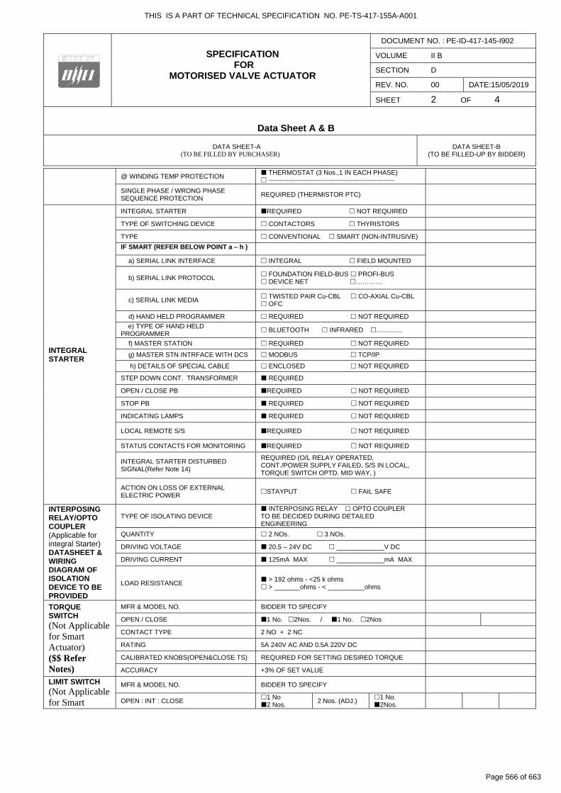
@ WINDING TEMP PROTECTION THERMOSTAT (3 Nos.,1 IN EACH PHASE) ---------------------------------------------------------
SINGLE PHASE / WRONG PHASE SEQUENCE PROTECTION
REQUIRED (THERMISTOR PTC)
INTEGRAL STARTER
INTEGRAL STARTER REQUIRED NOT REQUIRED
TYPE OF SWITCHING DEVICE CONTACTORS THYRISTORS
TYPE CONVENTIONAL SMART (NON-INTRUSIVE)
IF SMART (REFER BELOW POINT a – h )
a) SERIAL LINK INTERFACE INTEGRAL FIELD MOUNTED
b) SERIAL LINK PROTOCOL FOUNDATION FIELD-BUS PROFI-BUS DEVICE NET …………
c) SERIAL LINK MEDIA TWISTED PAIR Cu-CBL CO-AXIAL Cu-CBL OFC
d) HAND HELD PROGRAMMER REQUIRED NOT REQUIRED
e) TYPE OF HAND HELD PROGRAMMER
BLUETOOTH INFRARED ..............
f) MASTER STATION REQUIRED NOT REQUIRED
g) MASTER STN INTRFACE WITH DCS MODBUS TCP/IP
h) DETAILS OF SPECIAL CABLE ENCLOSED NOT REQUIRED
STEP DOWN CONT. TRANSFORMER REQUIRED
OPEN / CLOSE PB REQUIRED NOT REQUIRED
STOP PB REQUIRED NOT REQUIRED
INDICATING LAMPS REQUIRED NOT REQUIRED
LOCAL REMOTE S/S REQUIRED NOT REQUIRED
STATUS CONTACTS FOR MONITORING REQUIRED NOT REQUIRED
INTEGRAL STARTER DISTURBED SIGNAL(Refer Note 14)
REQUIRED (O/L RELAY OPERATED, CONT./POWER SUPPLY FAILED, S/S IN LOCAL, TORQUE SWITCH OPTD. MID WAY, )
ACTION ON LOSS OF EXTERNAL ELECTRIC POWER
STAYPUT FAIL SAFE
INTERPOSING RELAY/OPTO COUPLER (Applicable for integral Starter) DATASHEET & WIRING DIAGRAM OF ISOLATION DEVICE TO BE PROVIDED
TYPE OF ISOLATING DEVICE INTERPOSING RELAY OPTO COUPLER TO BE DECIDED DURING DETAILED ENGINEERING
QUANTITY 2 NOs. 3 NOs.
DRIVING VOLTAGE 20.5 – 24V DC _____________V DC
DRIVING CURRENT 125mA MAX _____________mA MAX
LOAD RESISTANCE > 192 ohms - <25 k ohms > _______ohms - < __________ohms
TORQUE SWITCH (Not Applicable for Smart Actuator) ($$ Refer Notes)
MFR & MODEL NO. BIDDER TO SPECIFY
OPEN / CLOSE 1 No. 2Nos. / 1 No. 2Nos
CONTACT TYPE 2 NO + 2 NC
RATING 5A 240V AC AND 0.5A 220V DC
CALIBRATED KNOBS(OPEN&CLOSE TS) REQUIRED FOR SETTING DESIRED TORQUE
ACCURACY +3% OF SET VALUE
LIMIT SWITCH (Not Applicable for Smart
MFR & MODEL NO. BIDDER TO SPECIFY
OPEN : INT : CLOSE 1 No 2 Nos.
2 Nos. (ADJ.) 1 No. 2Nos.
THIS IS A PART OF TECHNICAL SPECIFICATION NO. PE-TS-417-155A-A001
Page 566 of 663
SPECIFICATION FOR
MOTORISED VALVE ACTUATOR
DOCUMENT NO. : PE-ID-417-145-I902
VOLUME II B
SECTION D
REV. NO. 00 DATE:15/05/2019
SHEET 3 OF 4
Data Sheet A & B
DATA SHEET-A (TO BE FILLED BY PURCHASER)
DATA SHEET-B
(TO BE FILLED-UP BY BIDDER)
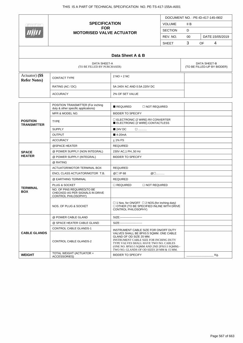
Actuator) ($$ Refer Notes)
CONTACT TYPE
2 NO + 2 NC
RATING (AC / DC) 5A 240V AC AND 0.5A 220V DC
ACCURACY 2% OF SET VALUE
POSITION TRANSMITTER
POSITION TRANSMITTER (For inching duty & other specific applications)
REQUIRED NOT REQUIRED
MFR & MODEL NO. BIDDER TO SPECIFY
TYPE ELECTRONIC (2 WIRE) R/I CONVERTER ELECTRONIC (2 WIRE) CONTACTLESS
SUPPLY 24V DC ………
OUTPUT 4-20mA
ACCURACY + 1% FS
SPACE HEATER
@SPACE HEATER REQUIRED
@ POWER SUPPLY (NON INTEGRAL) 230V AC,1 PH.,50 Hz
@ POWER SUPPLY (INTEGRAL) BIDDER TO SPECIFY
@ RATING
TERMINAL BOX
ACTUATOR/MOTOR TERMINAL BOX REQUIRED
ENCL CLASS ACTUATOR/MOTOR T.B. @ IP 68 @………
@ EARTHING TERMINAL REQUIRED
PLUG & SOCKET REQUIRED NOT REQUIRED
NO. OF PINS REQUIRED(TO BE CHECKED AS PER SIGNALS IN DRIVE CONTROL PHILOSOPHY)
NOS. OF PLUG & SOCKET
1 Nos. for ON/OFF 2 NOS.(for inching duty) OTHER (TO BE SPECIFIED INLINE WITH DRIVE CONTROL PHILOSOPHY)
CABLE GLANDS
@ POWER CABLE GLAND SIZE:-----------------------
@ SPACE HEATER CABLE GLAND SIZE:-----------------------
CONTROL CABLE GLANDS-1 INSTRUMENT CABLE SIZE FOR ON/OFF DUTY VALVES SHALL BE 8PX0.5 SQMM. ONE CABLE GLAND OF OD SIZE 20 MM. INSTRUMENT CABLE SIZE FOR INCHING DUTY TYPE VALVES SHALL HAVE TWO NO. CABLES (ONE NO. 8PXO.5 SQMM AND 2ND 2PXO.5 SQMM) - TWO NO. GLANDS OF OD SIZES 20 MM & 15 MM.
CONTROL CABLE GLANDS-2
WEIGHT TOTAL WEIGHT (ACTUATOR + ACCESSORIES)
BIDDER TO SPECIFY _________________ Kg.
THIS IS A PART OF TECHNICAL SPECIFICATION NO. PE-TS-417-155A-A001
Page 567 of 663
SPECIFICATION FOR
MOTORISED VALVE ACTUATOR
DOCUMENT NO. : PE-ID-417-145-I902
VOLUME II B
SECTION D
REV. NO. 00 DATE:15/05/2019
SHEET 4 OF 4
Data Sheet A & B
DATA SHEET-A (TO BE FILLED BY PURCHASER)
DATA SHEET-B
(TO BE FILLED-UP BY BIDDER)
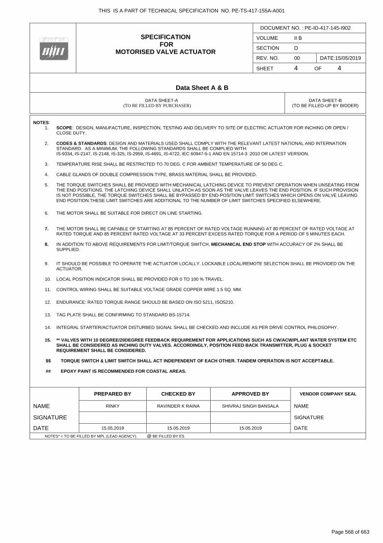
NOTES:
1. SCOPE: DESIGN, MANUFACTURE, INSPECTION, TESTING AND DELIVERY TO SITE OF ELECTRIC ACTUATOR FOR INCHING OR OPEN / CLOSE DUTY.
2. CODES & STANDARDS: DESIGN AND MATERIALS USED SHALL COMPLY WITH THE RELEVANT LATEST NATIONAL AND INTERNATION
STANDARD. AS A MINIMUM, THE FOLLOWING STANDARDS SHALL BE COMPLIED WITH: IS-9334, IS-2147, IS-2148, IS-325, IS-2959, IS-4691, IS-4722, IEC 60947-5-1 AND EN 15714-3 :2010 OR LATEST VERSION.
3. TEMPERATURE RISE SHALL BE RESTRICTED TO 70 DEG. C FOR AMBIENT TEMPERATURE OF 50 DEG C. 4. CABLE GLANDS OF DOUBLE COMPRESSION TYPE, BRASS MATERIAL SHALL BE PROVIDED. 5. THE TORQUE SWITCHES SHALL BE PROVIDED WITH MECHANICAL LATCHING DEVICE TO PREVENT OPERATION WHEN UNSEATING FROM
THE END POSITIONS. THE LATCHING DEVICE SHALL UNLATCH AS SOON AS THE VALVE LEAVES THE END POSITION. IF SUCH PROVISION IS NOT POSSIBLE, THE TORQUE SWITCHES SHALL BE BYPASSED BY END-POSITION LIMIT SWITCHES WHICH OPENS ON VALVE LEAVING END POSITION.THESE LIMIT SWITCHES ARE ADDITIONAL TO THE NUMBER OF LIMIT SWITCHES SPECIFIED ELSEWHERE.
6. THE MOTOR SHALL BE SUITABLE FOR DIRECT ON LINE STARTING.
7. THE MOTOR SHALL BE CAPABLE OF STARTING AT 85 PERCENT OF RATED VOLTAGE RUNNING AT 80 PERCENT OF RATED VOLTAGE AT
RATED TORQUE AND 85 PERCENT RATED VOLTAGE AT 33 PERCENT EXCESS RATED TORQUE FOR A PERIOD OF 5 MINUTES EACH.
8. IN ADDITION TO ABOVE REQUIREMENTS FOR LIMIT/TORQUE SWITCH, MECHANICAL END STOP WITH ACCURACY OF 2% SHALL BE SUPPLIED.
9. IT SHOULD BE POSSIBLE TO OPERATE THE ACTUATOR LOCALLY. LOCKABLE LOCAL/REMOTE SELECTION SHALL BE PROVIDED ON THE ACTUATOR.
10. LOCAL POSITION INDICATOR SHALL BE PROVIDED FOR 0 TO 100 % TRAVEL.
11. CONTROL WIRING SHALL BE SUITABLE VOLTAGE GRADE COPPER WIRE 1.5 SQ. MM.
12. ENDURANCE: RATED TORQUE RANGE SHOULD BE BASED ON ISO 5211, ISO5210.
13. TAG PLATE SHALL BE CONFIRMING TO STANDARD BS-15714.
14. INTEGRAL STARTER/ACTUATOR DISTURBED SIGNAL SHALL BE CHECKED AND INCLUDE AS PER DRIVE CONTROL PHILOSOPHY.
15. ** VALVES WITH 10 DEGREE/20DEGREE FEEDBACK REQUIREMENT FOR APPLICATIONS SUCH AS CW/ACW/PLANT WATER SYSTEM ETC
SHALL BE CONSIDERED AS INCHING DUTY VALVES. ACCORDINGLY, POSITION FEED BACK TRANSMITTER, PLUG & SOCKET REQUIREMENT SHALL BE CONSIDERED.
$$ TORQUE SWITCH & LIMIT SWITCH SHALL ACT INDEPENDENT OF EACH OTHER. TANDEM OPERATION IS NOT ACCEPTABLE. ## EPOXY PAINT IS RECOMMENDED FOR COASTAL AREAS.
PREPARED BY CHECKED BY APPROVED BY VENDOR COMPANY SEAL
NAME RINKY RAVINDER K RAINA SHIVRAJ SINGH BANSALA NAME
SIGNATURE SIGNATURE
DATE 15.05.2019 15.05.2019 15.05.2019 DATE
NOTES* = TO BE FILLED BY MPL (LEAD AGENCY). @ BE FILLED BY ES
THIS IS A PART OF TECHNICAL SPECIFICATION NO. PE-TS-417-155A-A001
Page 568 of 663

THIS IS A PART OF TECHNICAL SPECIFICATION NO. PE-TS-417-155A-A001
Page 569 of 663
Technical specification forCONTROL & INSTRUMENTATION
5x800 MW YADADRI TPS, NALGONDA
SPEC NO.: PE-TS-417-145-I
VOLUME
SECTION
REV. NO. 00 DATE : 03.04.2018
SHEET OF
FOR
M N
O. P
EM
-666
6-0
INSTRUMENTATION DATA SHEET
THIS IS A PART OF TECHNICAL SPECIFICATION NO. PE-TS-417-155A-A001
Page 570 of 663
Telangana State Power Generation Corporation Ltd. EPC Bid Document 1x800 MW Kothagudem TPS e-PCT/TS/K/02/2014-15
DEVELOPMENT CONSULTANTS V VI/S-VII/SS-B: 1 (PCT-K-03-2013-14_V-VI_S VII_SS B.DOC)
VOLUME : VI SECTION-VII
SUB SECTION - B CONTROL VALVES
THIS IS A PART OF TECHNICAL SPECIFICATION NO. PE-TS-417-155A-A001
Page 571 of 663

Telangana State Power Generation Corporation Ltd. EPC Bid Document 1x800 MW Kothagudem TPS e-PCT/TS/K/02/2014-15
DEVELOPMENT CONSULTANTS V VI/S-VII/SS-B: 2 (PCT-K-03-2013-14_V-VI_S VII_SS B.DOC)
1.00.00 GENERAL1.01.00 Control valves for regulating service shall normally be globe body, preferably
cage guided, metal-to-metal seated, pneumatically operated and shall be provided with characterized plugs
1.02.00 Where high stroking speed , high actuation forces and accurate positioning is critical for the operation of the plant, as in case of HP or LP bypass valves, Separator Drain Valves , hydraulic actuators with electro-hydraulic interface shall be offered.
2.00.00 GENERAL TECHNICAL REQUIREMENTS2.01.00 Bidder shall exercise caution in selecting severe service control valves like
BFP recirculation, HP & LP bypass, superheater & reheater attemperator, PRDS for Boiler & Turbine, Feed control station ,Soot blower steam pressure, Fuel oil heating and pressurizing ,minimum economizer flow control ,DM make up ( emergency / normal ), control valves whose down stream are connected to vacuum such as HP/LP heater emergency level control, condenser make up water, separator level control , CEP minimum flow control etc. For such critical applications, Bidder shall offer valves which are proven for similar application. Above valves shall have leakage class equal or better than class-VI with metal-to-metal seating.
2.02.00 Valve with ANSI leakage class-V shall be provided for all applications except for the control valves indicated above.
2.03.00 Bidder shall provide redundant control valves for some services such as Main condensate flow control, Superheat attemperation control and Reheat attemperation control as a minimum for high availability. For other application, if the availability criteria for the plant cannot be met even with the best established product, redundant control valves shall be provided.
2.04.00 Control valves shall be located near floor or platform for ease of access and with adequate clearances for maintenance and lay-down and shall be placed as station with upstream motorized isolating valve, down-stream motorized isolating valve, inching duty motorized bypass valve and manual drain valves. Each redundant control valve shall have its upstream motorized and down-stream motorised isolating valves. Where quick shut off requirement is foreseen such as in case of SH & RH attemperation valves, upstream isolation valve shall be pneumatic type.
2.05.00 Wherever, steam conditioning calls for , Pressure reducing & desuperheating, combined PRDS type valves shall be offered.
2.06.00 Control Valve shall be furnished with IBR certification wherever required .
2.07.00 Valve Body / End Connections
2.07.01 Valve end to end dimension and connection shall be according to ANSI standard, straight through pattern. However, Bidder may offer angle body valve for high pressure drop applications. For high pressure drop applications, construction of the valve shall be such that the gland is not exposed to inlet pressure.
2.07.02 Control valves of 40 mm. size and above with line pressure up to 50 Kg / Sq. cm may have flanged or welded end connections.
THIS IS A PART OF TECHNICAL SPECIFICATION NO. PE-TS-417-155A-A001
Page 572 of 663
Telangana State Power Generation Corporation Ltd. EPC Bid Document 1x800 MW Kothagudem TPS e-PCT/TS/K/02/2014-15
DEVELOPMENT CONSULTANTS V VI/S-VII/SS-B: 3 (PCT-K-03-2013-14_V-VI_S VII_SS B.DOC)
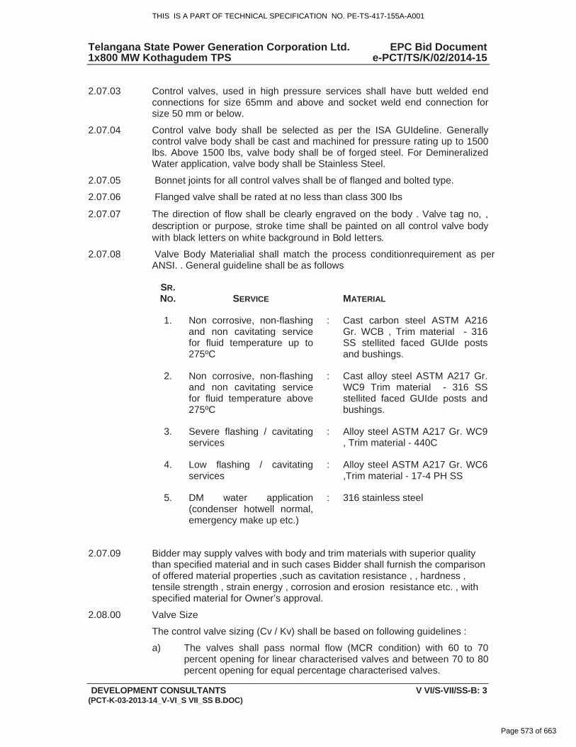
2.07.03 Control valves, used in high pressure services shall have butt welded end connections for size 65mm and above and socket weld end connection for size 50 mm or below.
2.07.04 Control valve body shall be selected as per the ISA GUIdeline. Generally control valve body shall be cast and machined for pressure rating up to 1500 lbs. Above 1500 lbs, valve body shall be of forged steel. For Demineralized Water application, valve body shall be Stainless Steel.
2.07.05 Bonnet joints for all control valves shall be of flanged and bolted type.
2.07.06 Flanged valve shall be rated at no less than class 300 Ibs
2.07.07 The direction of flow shall be clearly engraved on the body . Valve tag no, , description or purpose, stroke time shall be painted on all control valve body with black letters on white background in Bold letters.
2.07.08 Valve Body Materialial shall match the process conditionrequirement as per ANSI. . General guideline shall be as follows
SR.NO. SERVICE MATERIAL
1. Non corrosive, non-flashing and non cavitating service for fluid temperature up to 275ºC
: Cast carbon steel ASTM A216 Gr. WCB , Trim material - 316 SS stellited faced GUIde posts and bushings.
2. Non corrosive, non-flashing and non cavitating service for fluid temperature above 275ºC
: Cast alloy steel ASTM A217 Gr. WC9 Trim material - 316 SS stellited faced GUIde posts and bushings.
3. Severe flashing / cavitating services
: Alloy steel ASTM A217 Gr. WC9 , Trim material - 440C
4. Low flashing / cavitating services
: Alloy steel ASTM A217 Gr. WC6 ,Trim material - 17-4 PH SS
5. DM water application (condenser hotwell normal, emergency make up etc.)
: 316 stainless steel
2.07.09 Bidder may supply valves with body and trim materials with superior quality than specified material and in such cases Bidder shall furnish the comparison of offered material properties ,such as cavitation resistance , , hardness , tensile strength , strain energy , corrosion and erosion resistance etc. , with specified material for Owner’s approval.
2.08.00 Valve Size
The control valve sizing (Cv / Kv) shall be based on following guidelines :
a) The valves shall pass normal flow (MCR condition) with 60 to 70 percent opening for linear characterised valves and between 70 to 80 percent opening for equal percentage characterised valves.
THIS IS A PART OF TECHNICAL SPECIFICATION NO. PE-TS-417-155A-A001
Page 573 of 663
Telangana State Power Generation Corporation Ltd. EPC Bid Document 1x800 MW Kothagudem TPS e-PCT/TS/K/02/2014-15
DEVELOPMENT CONSULTANTS V VI/S-VII/SS-B: 4 (PCT-K-03-2013-14_V-VI_S VII_SS B.DOC)
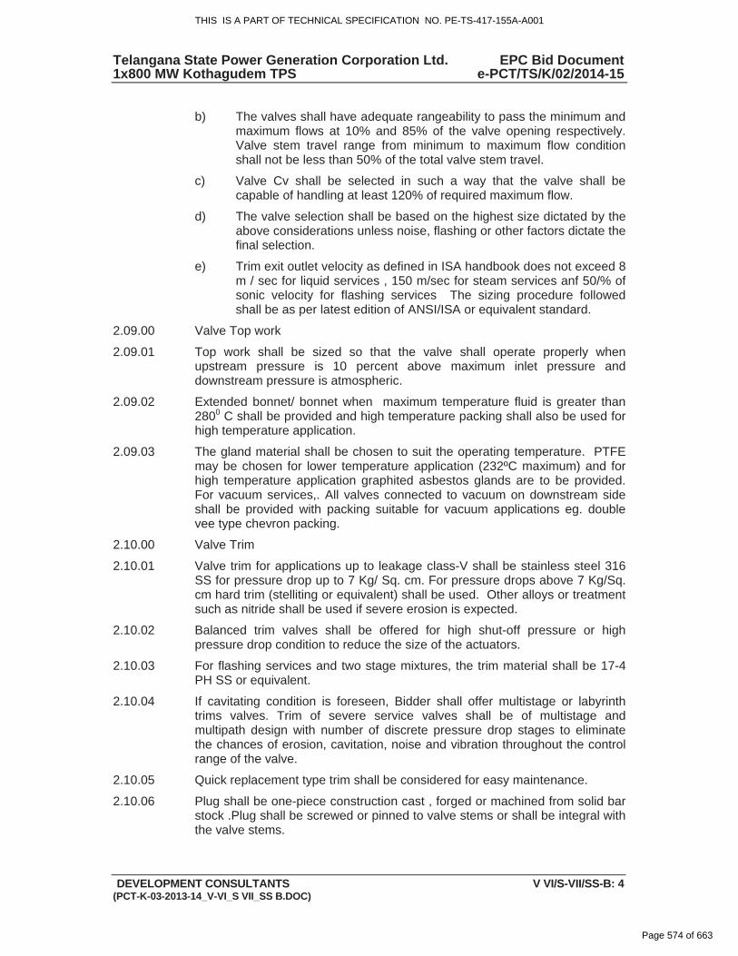
b) The valves shall have adequate rangeability to pass the minimum and maximum flows at 10% and 85% of the valve opening respectively. Valve stem travel range from minimum to maximum flow condition shall not be less than 50% of the total valve stem travel.
c) Valve Cv shall be selected in such a way that the valve shall be capable of handling at least 120% of required maximum flow.
d) The valve selection shall be based on the highest size dictated by the above considerations unless noise, flashing or other factors dictate the final selection.
e) Trim exit outlet velocity as defined in ISA handbook does not exceed 8 m / sec for liquid services , 150 m/sec for steam services anf 50/% of sonic velocity for flashing services The sizing procedure followed shall be as per latest edition of ANSI/ISA or equivalent standard.
2.09.00 Valve Top work
2.09.01 Top work shall be sized so that the valve shall operate properly when upstream pressure is 10 percent above maximum inlet pressure and downstream pressure is atmospheric.
2.09.02 Extended bonnet/ bonnet when maximum temperature fluid is greater than 2800 C shall be provided and high temperature packing shall also be used for high temperature application.
2.09.03 The gland material shall be chosen to suit the operating temperature. PTFE may be chosen for lower temperature application (232ºC maximum) and for high temperature application graphited asbestos glands are to be provided. For vacuum services,. All valves connected to vacuum on downstream side shall be provided with packing suitable for vacuum applications eg. double vee type chevron packing.
2.10.00 Valve Trim
2.10.01 Valve trim for applications up to leakage class-V shall be stainless steel 316 SS for pressure drop up to 7 Kg/ Sq. cm. For pressure drops above 7 Kg/Sq. cm hard trim (stelliting or equivalent) shall be used. Other alloys or treatment such as nitride shall be used if severe erosion is expected.
2.10.02 Balanced trim valves shall be offered for high shut-off pressure or high pressure drop condition to reduce the size of the actuators.
2.10.03 For flashing services and two stage mixtures, the trim material shall be 17-4 PH SS or equivalent.
2.10.04 If cavitating condition is foreseen, Bidder shall offer multistage or labyrinth trims valves. Trim of severe service valves shall be of multistage and multipath design with number of discrete pressure drop stages to eliminate the chances of erosion, cavitation, noise and vibration throughout the control range of the valve.
2.10.05 Quick replacement type trim shall be considered for easy maintenance.
2.10.06 Plug shall be one-piece construction cast , forged or machined from solid bar stock .Plug shall be screwed or pinned to valve stems or shall be integral with the valve stems.
THIS IS A PART OF TECHNICAL SPECIFICATION NO. PE-TS-417-155A-A001
Page 574 of 663
Telangana State Power Generation Corporation Ltd. EPC Bid Document 1x800 MW Kothagudem TPS e-PCT/TS/K/02/2014-15
DEVELOPMENT CONSULTANTS V VI/S-VII/SS-B: 5 (PCT-K-03-2013-14_V-VI_S VII_SS B.DOC)
2.11.00 Noise Level
The equivalent sound level measured at 1.5M above nearest floor level in elevation and 1 M horizontally from the control valve expressed in decibels to a reference of 0.0002 microbar shall not exceed 85 dBA. The noise abatement shall be achieved by valve body & trim design and not by use of silenecers. Valve Actuators
2.12.00 Actuator
2.12.01 Spring-diaphragm type actuators shall generally be used. Piston type actuators shall be offered in case of high shut-off pressure & quick response requirement. Hydraulic actuation system shall be provided for Critical valves as described elsewhere in the specification.
2.12.02 The actuator shall be designed for 150% thrust required for the valve (at shut-off pressure) at an air line supply pressure of 5.5 Kg/Sq. cm.
2.12.03 Diaphragms shall be designed for 200% maximum operating pressure.
2.12.04 Nylon reinforced neoprene is preferred as diaphragm material.
2.12.05 Valve actuators shall be capable of operating at 800 C ambient, continuously.
2.12.06 Entire actuator assembly shall be painted with corrosion inhibiting paint.
2.12.07 Air connection size shall be 1/4” NPT (F) unless otherwise dictated by process response time. Integral tubing shall be stainless steel.
2.12.08 Bidder shall indicate the stroking time of the valve assemblies with ositioned and ensure that the stroke time shall meet the process and equipment dynamics and shall be better than 10 seconds.
2.12.09 All actuators shall be of fail safe design signifying that the spring direction will tend to move the valve (open or close) in a direction safe for the process. “Failure to Open” or “Failure to Close” shall be marked on the actuator.
2.12.10 Hydraulic actuation system
The system shall consist of , but not limited to , Hydraulic cylinder , proportional valve with blocking unit , SMART positioner with position transmitter , SOVs , safety bypass unit , safety control unit , Hydraulic supply unit and local controller cubicle with controller unit
2.13.00 Valve Positioners
2.13.01 All regulating service valves shall be offered with HART protocol based Smart Electro Pneumatic Positioners to ensure accuracy and repeatability of response.
2.13.02 Positioners shall have integral non contact type position transmitter, input and output gauges, local keypad & display and 4-20 mA DC output to DDCMIS in CCR.
2.13.03 Positioners shall be capable of functioning under hot, humid and vibrating conditions.
2.13.04 Positioner casings shall be dust tight, corrosion resistant and weatherproof to IP 65 .and explosion proof in hazardous areas.
THIS IS A PART OF TECHNICAL SPECIFICATION NO. PE-TS-417-155A-A001
Page 575 of 663
Telangana State Power Generation Corporation Ltd. EPC Bid Document 1x800 MW Kothagudem TPS e-PCT/TS/K/02/2014-15
DEVELOPMENT CONSULTANTS V VI/S-VII/SS-B: 6 (PCT-K-03-2013-14_V-VI_S VII_SS B.DOC)
2.13.05 In general, positioner shall operate at signal range 4 – 20 mA DC for the full travel of the valve. Split range operation in few cases may be required.
2.13.06 Remote calibration from control room shall be possible through HART management station.
2.14.00 Performance
2.14.01 Performance of the complete assembly of the control valves shall be better than +/- 1% of FS for linearity , +/- 0.5 % of FS for hysteresis , 1% for accuracy.
2.15.00 Valve Accessories
2.15.01 Accessories shall include side mounted hand wheels, open & close , intermediate ( as applicable ) limit switches for both regulating and On off valves ,, junction boxes with 20 % spare terminals , Air filter regulators , airlock relays , volume chambers etc. Solenoid valve (SOV) wherever required shall be furnished. Each limit switch shall have not less than 2 NO & 2 NC contacts with contact rating 5A , 240 V AC / 0.5 A , 220 V DC . SOV shall have SS bar stock body , SS316 Trim , SS coil enclosure , Class H insulation Air filter regulator shall have sintered bronze filter element with maximum 5 microns filter size & 2 inch dial size pressure gauges. .Protection class of all Limit switches , junction boxes , SOV etc. shall have protection class IP 65 and explosion proof for hazardous areas.
2.15.02 Air distribution line to all final control elements like control valves, pneumatic dampers (both regulating / on-off type) , SOV operated valves shall be through SS manifolds and SS isolating valves only. These valves shall be properly tagged also with KKS tag no. and description of final control element / instrument for which they are intended.
2.16.00 Test and Examination
All valves shall be tested in accordance with the Quality Assurance programme agreed between the Owner and Bidder , which shall meet the requirements of IBR and other applicable codes mentioned elsewhere in the specification . The test shall include but not be limited to Non destructive test , Hydrostatic shell test prior to seat leakage test , Seat leakage test , Valve closure test , Functional test of fully assembled valves including actuators and accessories. CV test etc. For all control valves Cv test shall be witnessed by Owner.
THIS IS A PART OF TECHNICAL SPECIFICATION NO. PE-TS-417-155A-A001
Page 576 of 663
Telangana State Power Generation Corporation Ltd. EPC Bid Document 1x800 MW Kothagudem TPS e-PCT/TS/K/02/2014-15
DEVELOPMENT CONSULTANTS V VI/S-VII/SS-A: 2(PCT-K-03-2013-14_V-VI_S VII_SS A.DOC)
1.00.00 SPECIFICATION FOR ELECTRONIC TRANSMITTERS
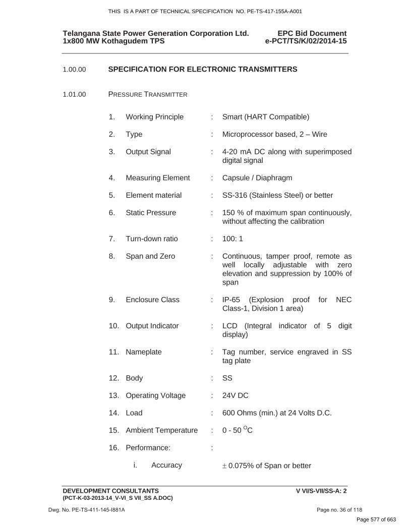
1.01.00 PRESSURE TRANSMITTER
1. Working Principle : Smart (HART Compatible)
2. Type : Microprocessor based, 2 – Wire
3. Output Signal : 4-20 mA DC along with superimposed digital signal
4. Measuring Element : Capsule / Diaphragm
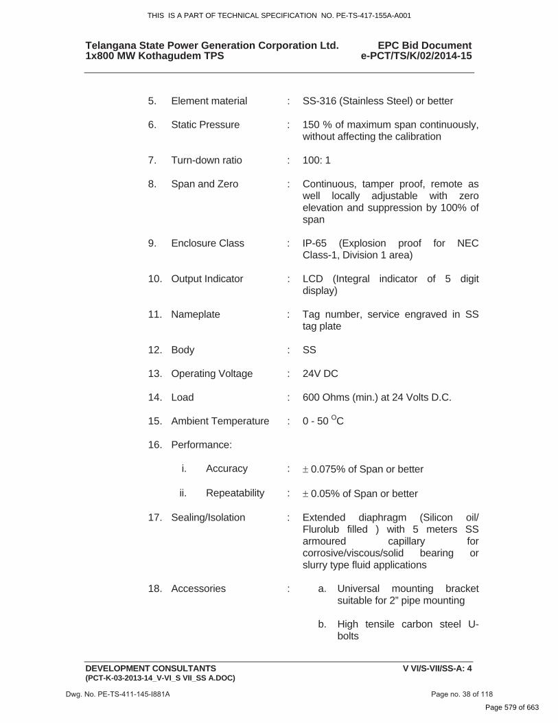
5. Element material : SS-316 (Stainless Steel) or better
6. Static Pressure : 150 % of maximum span continuously, without affecting the calibration
7. Turn-down ratio : 100: 1
8. Span and Zero : Continuous, tamper proof, remote as well locally adjustable with zero elevation and suppression by 100% of span
9. Enclosure Class : IP-65 (Explosion proof for NEC Class-1, Division 1 area)
10. Output Indicator : LCD (Integral indicator of 5 digit display)
11. Nameplate : Tag number, service engraved in SS tag plate
12. Body : SS
13. Operating Voltage : 24V DC
14. Load : 600 Ohms (min.) at 24 Volts D.C.
15. Ambient Temperature : 0 - 50 OC
16. Performance:
:
i. Accuracy � 0.075% of Span or better
Dwg. No. PE-TS-411-145-I881A Page no. 36 of 118
THIS IS A PART OF TECHNICAL SPECIFICATION NO. PE-TS-417-155A-A001
Page 577 of 663
Telangana State Power Generation Corporation Ltd. EPC Bid Document 1x800 MW Kothagudem TPS e-PCT/TS/K/02/2014-15
DEVELOPMENT CONSULTANTS V VI/S-VII/SS-A: 3(PCT-K-03-2013-14_V-VI_S VII_SS A.DOC)
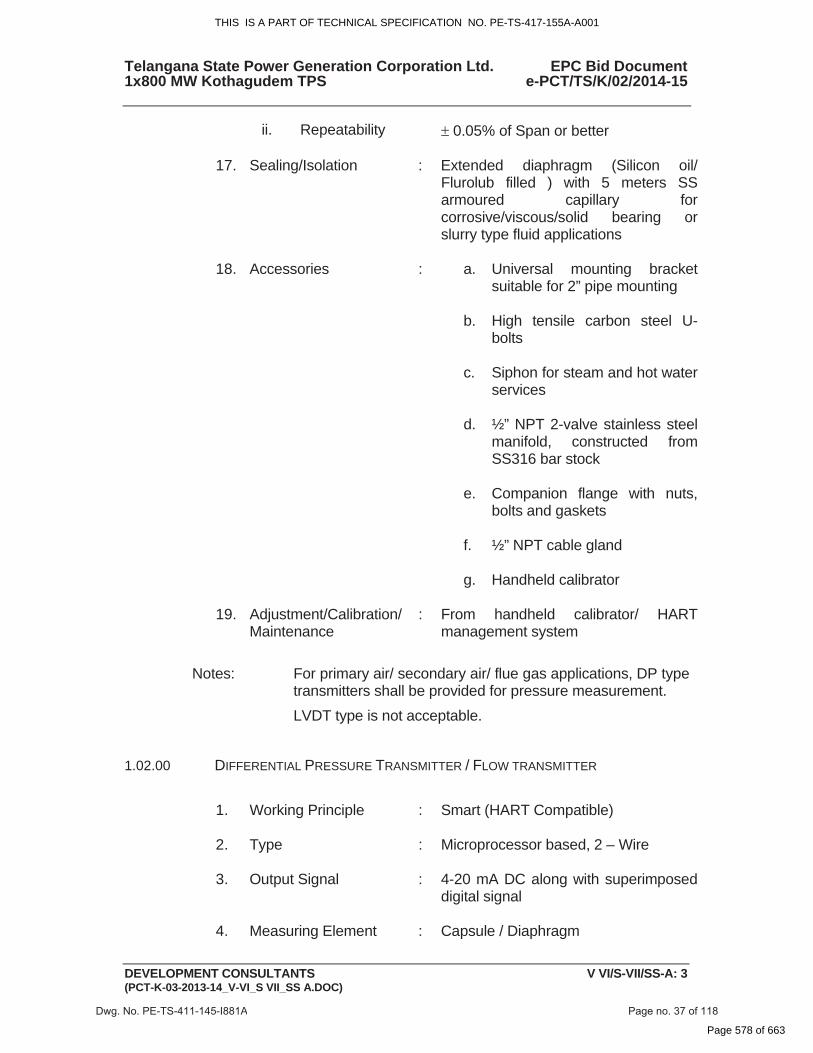
ii. Repeatability � 0.05% of Span or better
17. Sealing/Isolation : Extended diaphragm (Silicon oil/ Flurolub filled ) with 5 meters SS armoured capillary for corrosive/viscous/solid bearing or slurry type fluid applications
18. Accessories : a. Universal mounting bracket suitable for 2” pipe mounting
b. High tensile carbon steel U- bolts
c. Siphon for steam and hot water services
d. ½” NPT 2-valve stainless steel manifold, constructed from SS316 bar stock
e. Companion flange with nuts, bolts and gaskets
f. ½” NPT cable gland
g. Handheld calibrator
19. Adjustment/Calibration/ Maintenance
: From handheld calibrator/ HART management system
Notes: For primary air/ secondary air/ flue gas applications, DP type transmitters shall be provided for pressure measurement. LVDT type is not acceptable.
1.02.00 DIFFERENTIAL PRESSURE TRANSMITTER / FLOW TRANSMITTER
1. Working Principle : Smart (HART Compatible)
2. Type : Microprocessor based, 2 – Wire
3. Output Signal : 4-20 mA DC along with superimposed digital signal
4. Measuring Element : Capsule / Diaphragm
Dwg. No. PE-TS-411-145-I881A Page no. 37 of 118
THIS IS A PART OF TECHNICAL SPECIFICATION NO. PE-TS-417-155A-A001
Page 578 of 663
Telangana State Power Generation Corporation Ltd. EPC Bid Document 1x800 MW Kothagudem TPS e-PCT/TS/K/02/2014-15
DEVELOPMENT CONSULTANTS V VI/S-VII/SS-A: 4(PCT-K-03-2013-14_V-VI_S VII_SS A.DOC)
5. Element material : SS-316 (Stainless Steel) or better
6. Static Pressure : 150 % of maximum span continuously,
without affecting the calibration
7. Turn-down ratio : 100: 1
8. Span and Zero : Continuous, tamper proof, remote as well locally adjustable with zero elevation and suppression by 100% of span
9. Enclosure Class : IP-65 (Explosion proof for NEC Class-1, Division 1 area)
10. Output Indicator : LCD (Integral indicator of 5 digit display)
11. Nameplate : Tag number, service engraved in SS tag plate
12. Body : SS
13. Operating Voltage : 24V DC
14. Load : 600 Ohms (min.) at 24 Volts D.C.
15. Ambient Temperature : 0 - 50 OC
16. Performance:
i. Accuracy : � 0.075% of Span or better
ii. Repeatability : � 0.05% of Span or better
17. Sealing/Isolation : Extended diaphragm (Silicon oil/ Flurolub filled ) with 5 meters SS armoured capillary for corrosive/viscous/solid bearing or slurry type fluid applications
18. Accessories : a. Universal mounting bracket suitable for 2” pipe mounting
b. High tensile carbon steel U- bolts
Dwg. No. PE-TS-411-145-I881A Page no. 38 of 118
THIS IS A PART OF TECHNICAL SPECIFICATION NO. PE-TS-417-155A-A001
Page 579 of 663
Telangana State Power Generation Corporation Ltd. EPC Bid Document 1x800 MW Kothagudem TPS e-PCT/TS/K/02/2014-15
DEVELOPMENT CONSULTANTS V VI/S-VII/SS-A: 5(PCT-K-03-2013-14_V-VI_S VII_SS A.DOC)
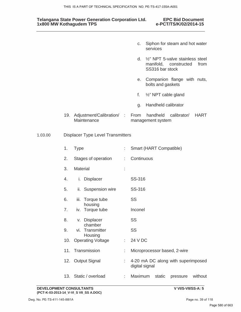
c. Siphon for steam and hot water
services
d. ½” NPT 5-valve stainless steel manifold, constructed from SS316 bar stock
e. Companion flange with nuts, bolts and gaskets
f. ½” NPT cable gland
g. Handheld calibrator
19. Adjustment/Calibration/ Maintenance
: From handheld calibrator/ HART management system
1.03.00 Displacer Type Level Transmitters
1. Type : Smart (HART Compatible)
2. Stages of operation : Continuous
3. Material :
4. i. Displacer SS-316
5. ii. Suspension wire SS-316
6. iii. Torque tube housing
SS
7. iv. Torque tube Inconel
8. v. Displacer chamber
SS
9. vi. Transmitter Housing
SS
10. Operating Voltage : 24 V DC
11. Transmission : Microprocessor based, 2-wire
12. Output Signal : 4-20 mA DC along with superimposed digital signal
13. Static / overload : Maximum static pressure without
Dwg. No. PE-TS-411-145-I881A Page no. 39 of 118
THIS IS A PART OF TECHNICAL SPECIFICATION NO. PE-TS-417-155A-A001
Page 580 of 663

Telangana State Power Generation Corporation Ltd. EPC Bid Document 1x800 MW Kothagudem TPS e-PCT/TS/K/02/2014-15
DEVELOPMENT CONSULTANTS V VI/S-VII/SS-A: 6(PCT-K-03-2013-14_V-VI_S VII_SS A.DOC)
pressure permanent deformation or loss of accuracy
14. Turn-down ratio : 10 : 1 or better
15. Zero & Span : Continuous, tamper proof, remote as well locally adjustable with zero elevation and suppression by 100% of span
16. Enclosure Class : IP-65
17. Output Indicator : LCD type (Integral indicator of 5 digit display)
18. Nameplate : Tag number and Service engraved in stainless steel tag plate
19. Ambient Temperature : 0 - 50 OC
20. Load Impedance : 600 Ohms at 24 Volts (minimum)
21. Process Connection : 2” Flanged
22. Performance - Accuracy
: +_ 0.075 % of span or better
23. Accessories : a) Counter Flange, nuts, bolts, gaskets etc
b) Weights for 5 point calibration of instruments
c) Vent and drain plugs
d) ½” NPT Glands
e) Handheld calibrator
24. Preferred Features : a) Test plug connection and cutout terminals physically separated from other electronics
b) Electronic Damping facility (adjustable)
25. Adjustment/Calibration/ Maintenance
: From handheld calibrator/ HART management system
Dwg. No. PE-TS-411-145-I881A Page no. 40 of 118
THIS IS A PART OF TECHNICAL SPECIFICATION NO. PE-TS-417-155A-A001
Page 581 of 663
Telangana State Power Generation Corporation Ltd. EPC Bid Document 1x800 MW Kothagudem TPS e-PCT/TS/K/02/2014-15
DEVELOPMENT CONSULTANTS V VI/S-VII/SS-A: 7(PCT-K-03-2013-14_V-VI_S VII_SS A.DOC)
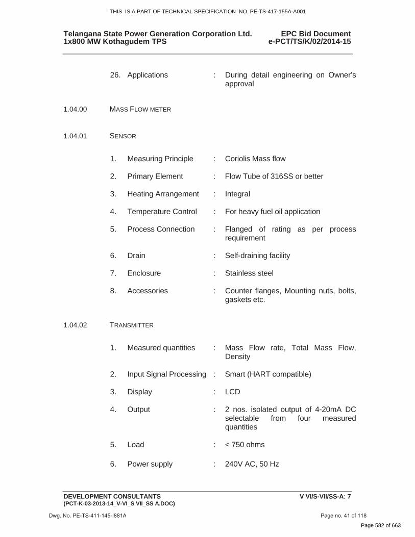
26. Applications : During detail engineering on Owner’s
approval 1.04.00 MASS FLOW METER
1.04.01 SENSOR
1. Measuring Principle : Coriolis Mass flow
2. Primary Element : Flow Tube of 316SS or better
3. Heating Arrangement : Integral
4. Temperature Control : For heavy fuel oil application
5. Process Connection : Flanged of rating as per process requirement
6. Drain : Self-draining facility
7. Enclosure : Stainless steel
8. Accessories : Counter flanges, Mounting nuts, bolts, gaskets etc.
1.04.02 TRANSMITTER
1. Measured quantities : Mass Flow rate, Total Mass Flow, Density
2. Input Signal Processing : Smart (HART compatible)
3. Display : LCD
4. Output : 2 nos. isolated output of 4-20mA DC selectable from four measured quantities
5. Load : < 750 ohms
6. Power supply : 240V AC, 50 Hz
Dwg. No. PE-TS-411-145-I881A Page no. 41 of 118
THIS IS A PART OF TECHNICAL SPECIFICATION NO. PE-TS-417-155A-A001
Page 582 of 663
Telangana State Power Generation Corporation Ltd. EPC Bid Document 1x800 MW Kothagudem TPS e-PCT/TS/K/02/2014-15
DEVELOPMENT CONSULTANTS V VI/S-VII/SS-A: 8(PCT-K-03-2013-14_V-VI_S VII_SS A.DOC)
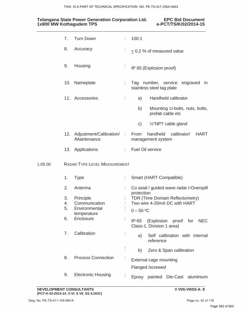
7. Turn Down : 100:1
8. Accuracy : +_ 0.2 % of measured value
9. Housing : IP 65 (Explosion proof)
10. Nameplate : Tag number, service engraved in stainless steel tag plate
11. Accessories : a) Handheld calibrator
b) Mounting U-bolts, nuts, bolts, prefab cable etc
c) ½”NPT cable gland
12. Adjustment/Calibration//Maintenance
: From handheld calibrator/ HART management system
13. Applications : Fuel Oil service 1.05.00 RADAR TYPE LEVEL MEASUREMENT
1. Type : Smart (HART Compatible)
2. Antenna : Co axial / guided wave radar / Overspill protection
3. Principle : TDR (Time Domain Reflectometry) 4. Communication : Two wire 4-20mA DC with HART 5. Environmental
temperature : 0 – 50 ºC
6. Enclosure : IP-65 (Explosion proof for NEC Class-1, Division 1 area)
7. Calibration : a) Self calibration with internal reference
: b) Zero & Span calibration 8. Process Connection : External cage mounting
Flanged /screwed 9. Electronic Housing : Epoxy painted Die-Cast aluminium
Dwg. No. PE-TS-411-145-I881A Page no. 42 of 118
THIS IS A PART OF TECHNICAL SPECIFICATION NO. PE-TS-417-155A-A001
Page 583 of 663
Telangana State Power Generation Corporation Ltd. EPC Bid Document 1x800 MW Kothagudem TPS e-PCT/TS/K/02/2014-15
DEVELOPMENT CONSULTANTS V VI/S-VII/SS-A: 9(PCT-K-03-2013-14_V-VI_S VII_SS A.DOC)
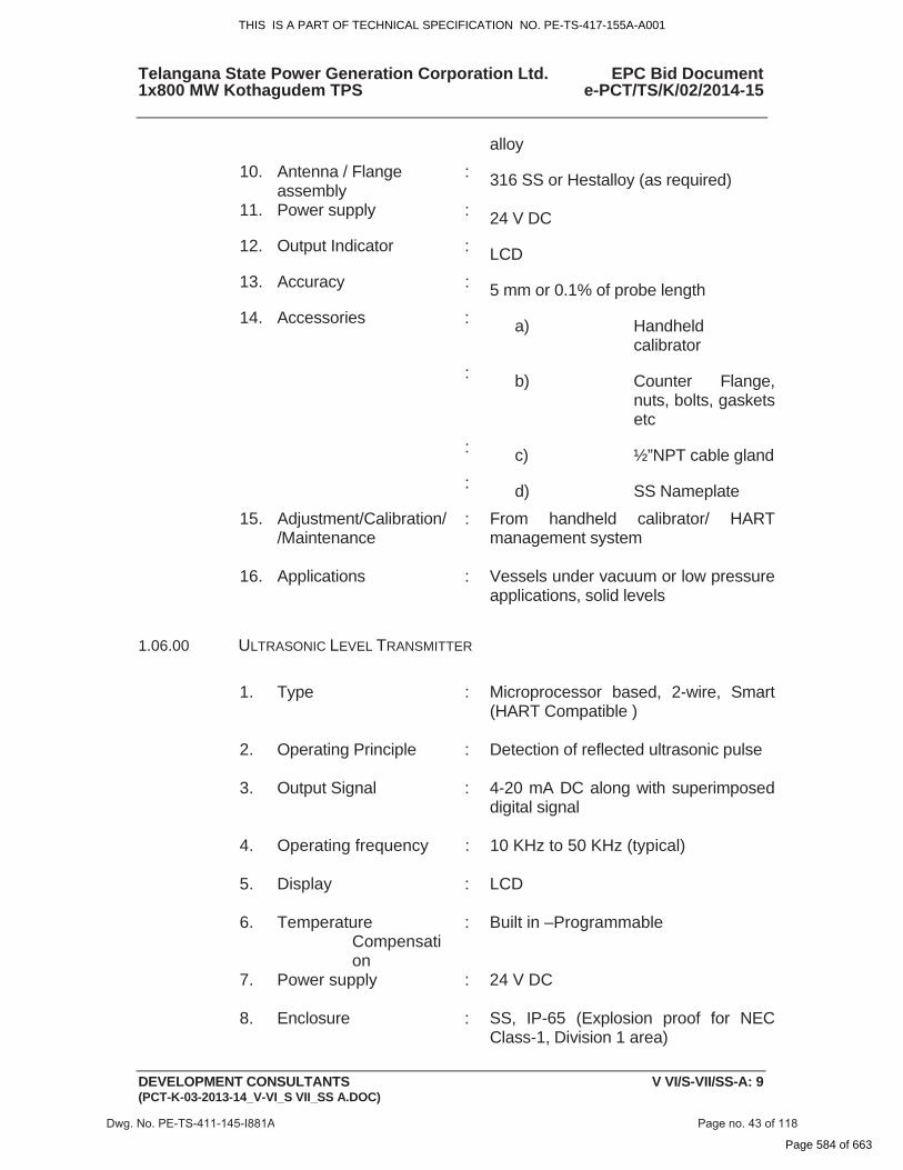
alloy 10. Antenna / Flange
assembly : 316 SS or Hestalloy (as required)
11. Power supply : 24 V DC 12. Output Indicator : LCD 13. Accuracy : 5 mm or 0.1% of probe length 14. Accessories : a) Handheld
calibrator : b) Counter Flange,
nuts, bolts, gaskets etc
: c) ½”NPT cable gland : d) SS Nameplate 15. Adjustment/Calibration/
/Maintenance : From handheld calibrator/ HART
management system
16. Applications : Vessels under vacuum or low pressure applications, solid levels
1.06.00 ULTRASONIC LEVEL TRANSMITTER
1. Type : Microprocessor based, 2-wire, Smart (HART Compatible )
2. Operating Principle : Detection of reflected ultrasonic pulse
3. Output Signal : 4-20 mA DC along with superimposed digital signal
4. Operating frequency : 10 KHz to 50 KHz (typical)
5. Display : LCD
6. Temperature Compensation
: Built in –Programmable
7. Power supply : 24 V DC
8. Enclosure : SS, IP-65 (Explosion proof for NEC Class-1, Division 1 area)
Dwg. No. PE-TS-411-145-I881A Page no. 43 of 118
THIS IS A PART OF TECHNICAL SPECIFICATION NO. PE-TS-417-155A-A001
Page 584 of 663
Telangana State Power Generation Corporation Ltd. EPC Bid Document 1x800 MW Kothagudem TPS e-PCT/TS/K/02/2014-15
DEVELOPMENT CONSULTANTS V VI/S-VII/SS-A: 10 (PCT-K-03-2013-14_V-VI_S VII_SS A.DOC)
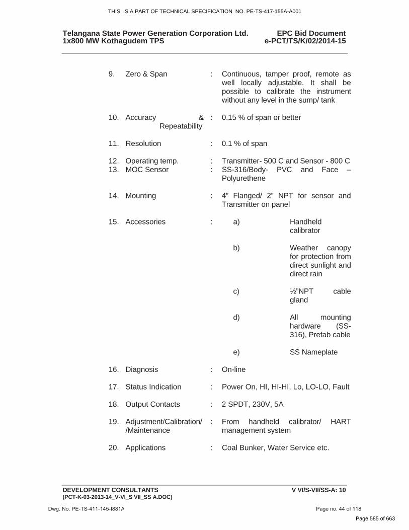
9. Zero & Span : Continuous, tamper proof, remote as
well locally adjustable. It shall be possible to calibrate the instrument without any level in the sump/ tank
10. Accuracy & Repeatability
: 0.15 % of span or better
11. Resolution : 0.1 % of span
12. Operating temp. : Transmitter- 500 C and Sensor - 800 C 13. MOC Sensor : SS-316/Body- PVC and Face –
Polyurethene
14. Mounting : 4” Flanged/ 2” NPT for sensor and Transmitter on panel
15. Accessories : a) Handheld calibrator
b) Weather canopy for protection from direct sunlight and direct rain
c) ½”NPT cable gland
d) All mounting hardware (SS-316), Prefab cable
e) SS Nameplate
16. Diagnosis : On-line
17. Status Indication : Power On, HI, HI-HI, Lo, LO-LO, Fault
18. Output Contacts : 2 SPDT, 230V, 5A
19. Adjustment/Calibration//Maintenance
: From handheld calibrator/ HART management system
20. Applications : Coal Bunker, Water Service etc.
Dwg. No. PE-TS-411-145-I881A Page no. 44 of 118
THIS IS A PART OF TECHNICAL SPECIFICATION NO. PE-TS-417-155A-A001
Page 585 of 663
Telangana State Power Generation Corporation Ltd. EPC Bid Document 1x800 MW Kothagudem TPS e-PCT/TS/K/02/2014-15
DEVELOPMENT CONSULTANTS V VI/S-VII/SS-A: 11 (PCT-K-03-2013-14_V-VI_S VII_SS A.DOC)
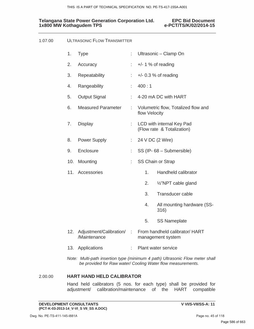
1.07.00 ULTRASONIC FLOW TRANSMITTER
1. Type : Ultrasonic – Clamp On
2. Accuracy : +/- 1 % of reading
3. Repeatability : +/- 0.3 % of reading
4. Rangeability : 400 : 1
5. Output Signal : 4-20 mA DC with HART
6. Measured Parameter : Volumetric flow, Totalized flow and flow Velocity
7. Display : LCD with internal Key Pad (Flow rate & Totalization)
8. Power Supply : 24 V DC (2 Wire)
9. Enclosure : SS (IP- 68 – Submersible)
10. Mounting : SS Chain or Strap
11. Accessories 1. Handheld calibrator
2. ½”NPT cable gland
3. Transducer cable
4. All mounting hardware (SS-316)
5. SS Nameplate
12. Adjustment/Calibration//Maintenance
: From handheld calibrator/ HART management system
13. Applications : Plant water service
Note: Multi-path insertion type (minimum 4 path) Ultrasonic Flow meter shall be provided for Raw water/ Cooling Water flow measurements.
2.00.00 HART HAND HELD CALIBRATOR
Hand held calibrators (5 nos. for each type) shall be provided for adjustment/ calibration/maintenance of the HART compatible
Dwg. No. PE-TS-411-145-I881A Page no. 45 of 118
THIS IS A PART OF TECHNICAL SPECIFICATION NO. PE-TS-417-155A-A001
Page 586 of 663
Telangana State Power Generation Corporation Ltd. EPC Bid Document 1x800 MW Kothagudem TPS e-PCT/TS/K/02/2014-15
DEVELOPMENT CONSULTANTS V VI/S-VII/SS-A: 12 (PCT-K-03-2013-14_V-VI_S VII_SS A.DOC)
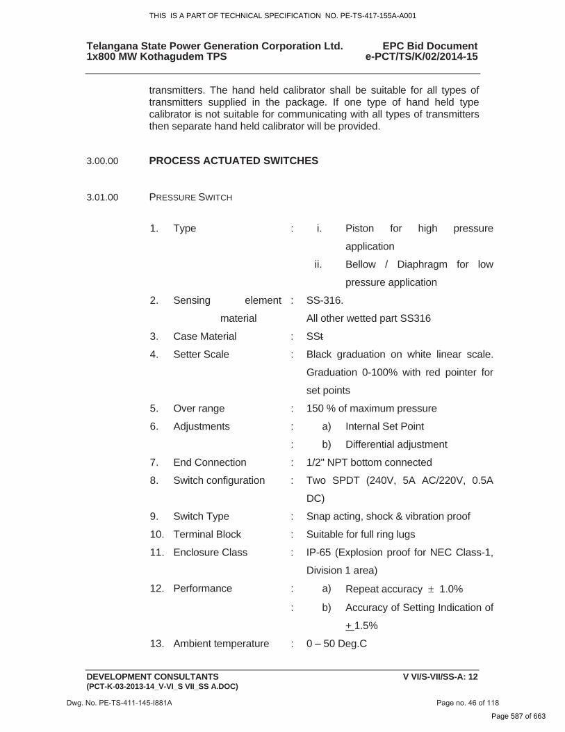
transmitters. The hand held calibrator shall be suitable for all types of transmitters supplied in the package. If one type of hand held type calibrator is not suitable for communicating with all types of transmitters then separate hand held calibrator will be provided.
3.00.00 PROCESS ACTUATED SWITCHES
3.01.00 PRESSURE SWITCH
1. Type : i. Piston for high pressure
application
ii. Bellow / Diaphragm for low
pressure application
2. Sensing element
material
: SS-316.
All other wetted part SS316
3. Case Material : SSt
4. Setter Scale : Black graduation on white linear scale.
Graduation 0-100% with red pointer for
set points
5. Over range : 150 % of maximum pressure
6. Adjustments : a) Internal Set Point
: b) Differential adjustment
7. End Connection : 1/2" NPT bottom connected
8. Switch configuration : Two SPDT (240V, 5A AC/220V, 0.5A
DC)
9. Switch Type : Snap acting, shock & vibration proof
10. Terminal Block : Suitable for full ring lugs
11. Enclosure Class : IP-65 (Explosion proof for NEC Class-1,
Division 1 area)
12. Performance : a) Repeat accuracy � 1.0%
: b) Accuracy of Setting Indication of
+ 1.5%
13. Ambient temperature : 0 – 50 Deg.C
Dwg. No. PE-TS-411-145-I881A Page no. 46 of 118
THIS IS A PART OF TECHNICAL SPECIFICATION NO. PE-TS-417-155A-A001
Page 587 of 663
Telangana State Power Generation Corporation Ltd. EPC Bid Document 1x800 MW Kothagudem TPS e-PCT/TS/K/02/2014-15
DEVELOPMENT CONSULTANTS V VI/S-VII/SS-A: 13 (PCT-K-03-2013-14_V-VI_S VII_SS A.DOC)
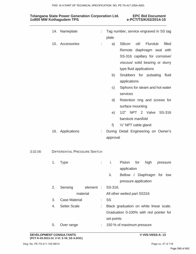
14. Nameplate : Tag number, service engraved in SS tag
plate
15. Accessories : a) Silicon oil/ Flurolub filled
Remote diaphragm seal with
SS-316 capillary for corrosive/
viscous/ solid bearing or slurry
type fluid applications
b) Snubbers for pulsating fluid
applications
c) Siphons for steam and hot water
services
d) Retention ring and screws for
surface mounting
e) 1/2” NPT 2 Valve SS-316
barstock manifold
f) ½” NPT cable gland
16. Applications : During Detail Engineering on Owner’s
approval
3.02.00 DIFFERENTIAL PRESSURE SWITCH
1. Type : i. Piston for high pressure
application
ii. Bellow / Diaphragm for low
pressure application
2. Sensing element
material
: SS-316.
All other wetted part SS316
3. Case Material : SS
4. Setter Scale : Black graduation on white linear scale.
Graduation 0-100% with red pointer for
set points
5. Over range : 150 % of maximum pressure
Dwg. No. PE-TS-411-145-I881A Page no. 47 of 118
THIS IS A PART OF TECHNICAL SPECIFICATION NO. PE-TS-417-155A-A001
Page 588 of 663
Telangana State Power Generation Corporation Ltd. EPC Bid Document 1x800 MW Kothagudem TPS e-PCT/TS/K/02/2014-15
DEVELOPMENT CONSULTANTS V VI/S-VII/SS-A: 14 (PCT-K-03-2013-14_V-VI_S VII_SS A.DOC)
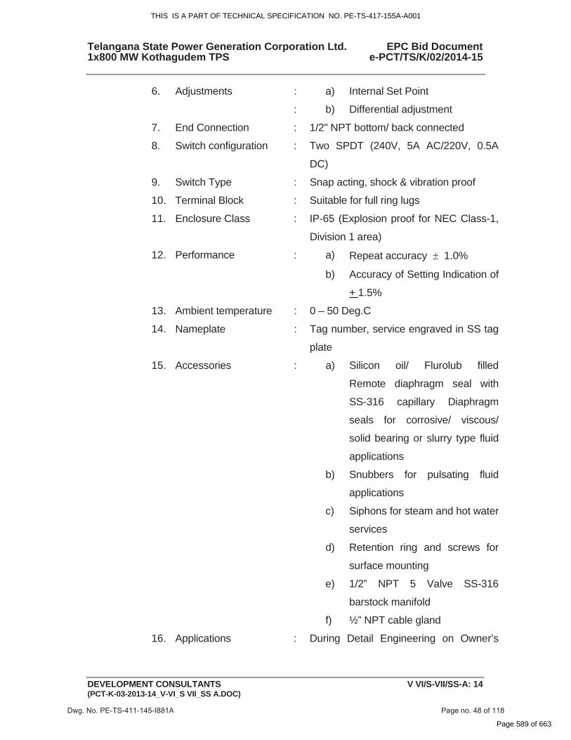
6. Adjustments : a) Internal Set Point
: b) Differential adjustment
7. End Connection : 1/2" NPT bottom/ back connected
8. Switch configuration : Two SPDT (240V, 5A AC/220V, 0.5A
DC)
9. Switch Type : Snap acting, shock & vibration proof
10. Terminal Block : Suitable for full ring lugs
11. Enclosure Class : IP-65 (Explosion proof for NEC Class-1,
Division 1 area)
12. Performance : a) Repeat accuracy � 1.0%
b) Accuracy of Setting Indication of
+ 1.5%
13. Ambient temperature : 0 – 50 Deg.C
14. Nameplate : Tag number, service engraved in SS tag
plate
15. Accessories : a) Silicon oil/ Flurolub filled
Remote diaphragm seal with
SS-316 capillary Diaphragm
seals for corrosive/ viscous/
solid bearing or slurry type fluid
applications
b) Snubbers for pulsating fluid
applications
c) Siphons for steam and hot water
services
d) Retention ring and screws for
surface mounting
e) 1/2” NPT 5 Valve SS-316
barstock manifold
f) ½” NPT cable gland
16. Applications : During Detail Engineering on Owner’s
Dwg. No. PE-TS-411-145-I881A Page no. 48 of 118
THIS IS A PART OF TECHNICAL SPECIFICATION NO. PE-TS-417-155A-A001
Page 589 of 663
Telangana State Power Generation Corporation Ltd. EPC Bid Document 1x800 MW Kothagudem TPS e-PCT/TS/K/02/2014-15
DEVELOPMENT CONSULTANTS V VI/S-VII/SS-A: 15 (PCT-K-03-2013-14_V-VI_S VII_SS A.DOC)
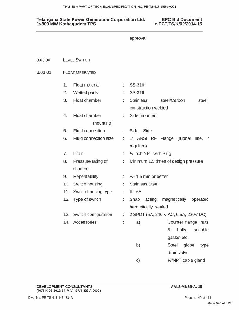
approval
3.03.00 LEVEL SWITCH
3.03.01 FLOAT OPERATED
1. Float material : SS-316
2. Wetted parts : SS-316
3. Float chamber : Stainless steel/Carbon steel,
construction welded
4. Float chamber
mounting
: Side mounted
5. Fluid connection : Side – Side
6. Fluid connection size : 1” ANSI RF Flange (rubber line, if
required)
7. Drain : ½ inch NPT with Plug
8. Pressure rating of
chamber
: Minimum 1.5 times of design pressure
9. Repeatability : +/- 1.5 mm or better
10. Switch housing : Stainless Steel
11. Switch housing type : IP- 65
12. Type of switch : Snap acting magnetically operated
hermetically sealed
13. Switch configuration : 2 SPDT (5A, 240 V AC, 0.5A, 220V DC)
14. Accessories : a) Counter flange, nuts
& bolts, suitable
gasket etc.
b) Steel globe type
drain valve
c) ½”NPT cable gland
Dwg. No. PE-TS-411-145-I881A Page no. 49 of 118
THIS IS A PART OF TECHNICAL SPECIFICATION NO. PE-TS-417-155A-A001
Page 590 of 663
Telangana State Power Generation Corporation Ltd. EPC Bid Document 1x800 MW Kothagudem TPS e-PCT/TS/K/02/2014-15
DEVELOPMENT CONSULTANTS V VI/S-VII/SS-A: 16 (PCT-K-03-2013-14_V-VI_S VII_SS A.DOC)
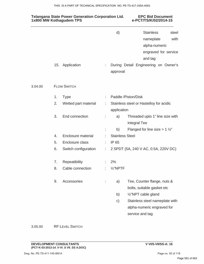
d) Stainless steel
nameplate with
alpha-numeric
engraved for service
and tag
15. Application : During Detail Engineering on Owner’s
approval
3.04.00 FLOW SWITCH
1. Type : Paddle /Piston/Disk
2. Wetted part material : Stainless steel or Hastelloy for acidic
application
3. End connection : a) Threaded upto 1” line size with
integral Tee
: b) Flanged for line size > 1 ½”
4. Enclosure material : Stainless Steel
5. Enclosure class : IP 65
6. Switch configuration : 2 SPDT (5A, 240 V AC, 0.5A, 220V DC)
7. Repeatibility : 2%
8. Cable connection : ½”NPTF
9. Accessories : a) Tee, Counter flange, nuts &
bolts, suitable gasket etc
b) ½”NPT cable gland
c) Stainless steel nameplate with
alpha-numeric engraved for
service and tag
3.05.00 RF LEVEL SWITCH
Dwg. No. PE-TS-411-145-I881A Page no. 50 of 118
THIS IS A PART OF TECHNICAL SPECIFICATION NO. PE-TS-417-155A-A001
Page 591 of 663

Telangana State Power Generation Corporation Ltd. EPC Bid Document 1x800 MW Kothagudem TPS e-PCT/TS/K/02/2014-15
DEVELOPMENT CONSULTANTS V VI/S-VII/SS-A: 17 (PCT-K-03-2013-14_V-VI_S VII_SS A.DOC)
1. Type : RADIO FREQUENCY
Sensing probe
2. Material : SS-316
3. Mounting : Threaded
4. Application
Temperature : 250°C (Max.)
Electronic Controller
5. Input Supply Voltage : 240V AC ±10%, 50 Hz.
6. Relay Output : 2 SPDT (240V AC, 5A)
7. Ambient Temperature : 50 °C
8. Enclosure Protection : IP-66
9. Enclosure Housing : SS
10. Local LED Indication :
Normal Level
Power On
Alarm Level
Probe Healthy
11. Switching Repeatability : ±0.5%
12. Accessories :
Co-axial cable for probe connection to
controller
SS Tag plate
½” NPT Cable Glands
13. Application : Solid level
3.06.00 CONDUCTIVITY TYPE LEVEL SWITCH
1. Type : Conductivity discrimination
2. Probe MOC : SS-316
3. Mounting : Flanged on external cage
4. Application
Temperature : 250°C (Max.)
5. Test Pressure : Two times rated pressure
Dwg. No. PE-TS-411-145-I881A Page no. 51 of 118
THIS IS A PART OF TECHNICAL SPECIFICATION NO. PE-TS-417-155A-A001
Page 592 of 663
Telangana State Power Generation Corporation Ltd. EPC Bid Document 1x800 MW Kothagudem TPS e-PCT/TS/K/02/2014-15
DEVELOPMENT CONSULTANTS V VI/S-VII/SS-A: 18 (PCT-K-03-2013-14_V-VI_S VII_SS A.DOC)
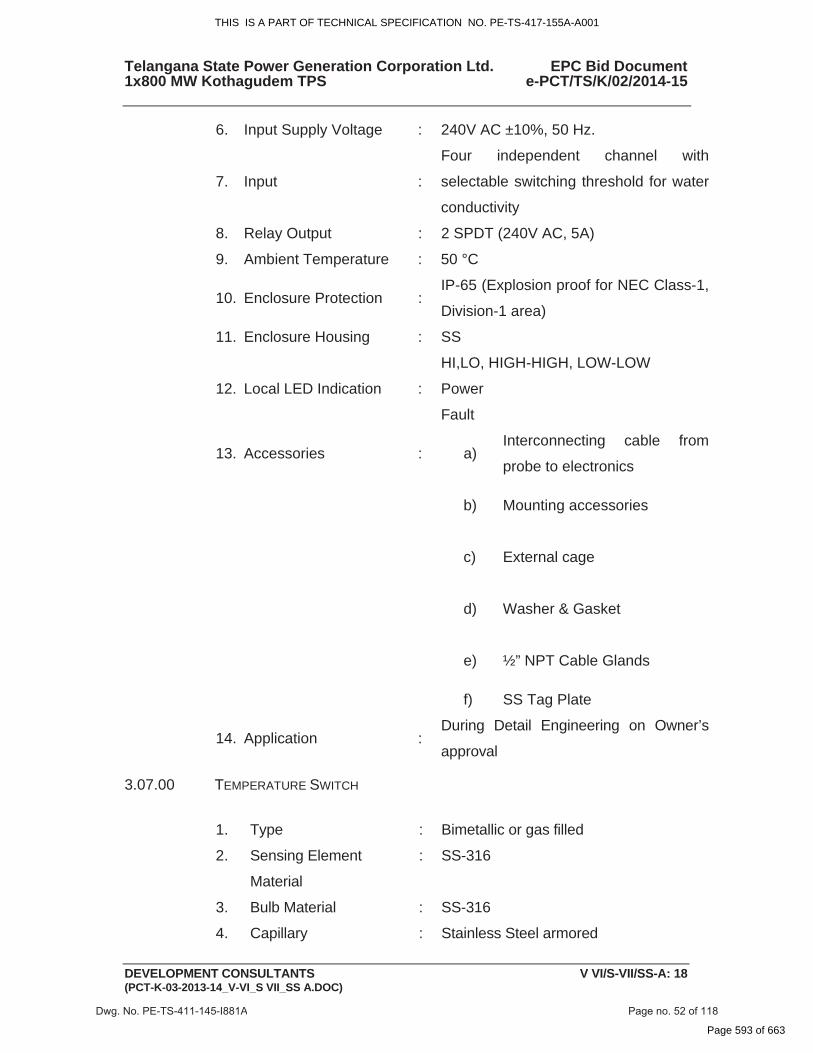
6. Input Supply Voltage : 240V AC ±10%, 50 Hz.
7. Input :
Four independent channel with
selectable switching threshold for water
conductivity
8. Relay Output : 2 SPDT (240V AC, 5A)
9. Ambient Temperature : 50 °C
10. Enclosure Protection : IP-65 (Explosion proof for NEC Class-1,
Division-1 area)
11. Enclosure Housing : SS
12. Local LED Indication :
HI,LO, HIGH-HIGH, LOW-LOW
Power
Fault
13. Accessories : a)Interconnecting cable from
probe to electronics
b) Mounting accessories
c) External cage
d) Washer & Gasket
e) ½” NPT Cable Glands
f) SS Tag Plate
14. Application : During Detail Engineering on Owner’s
approval
3.07.00 TEMPERATURE SWITCH
1. Type : Bimetallic or gas filled
2. Sensing Element
Material
: SS-316
3. Bulb Material : SS-316
4. Capillary : Stainless Steel armored
Dwg. No. PE-TS-411-145-I881A Page no. 52 of 118
THIS IS A PART OF TECHNICAL SPECIFICATION NO. PE-TS-417-155A-A001
Page 593 of 663
Telangana State Power Generation Corporation Ltd. EPC Bid Document 1x800 MW Kothagudem TPS e-PCT/TS/K/02/2014-15
DEVELOPMENT CONSULTANTS V VI/S-VII/SS-A: 19 (PCT-K-03-2013-14_V-VI_S VII_SS A.DOC)
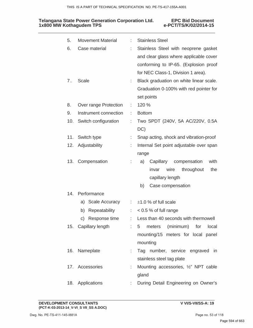
5. Movement Material : Stainless Steel
6. Case material : Stainless Steel with neoprene gasket
and clear glass where applicable cover
conforming to IP-65. (Explosion proof
for NEC Class-1, Division 1 area).
7.. Scale : Black graduation on white linear scale.
Graduation 0-100% with red pointer for
set points
8. Over range Protection : 120 %
9. Instrument connection : Bottom
10. Switch configuration : Two SPDT (240V, 5A AC/220V, 0.5A
DC)
11. Switch type : Snap acting, shock and vibration-proof
12. Adjustability : Internal Set point adjustable over span
range
13. Compensation : a) Capillary compensation with
invar wire throughout the
capillary length
b) Case compensation
14. Performance
a) Scale Accuracy : �1.0 % of full scale
b) Repeatability : < 0.5 % of full range
c) Response time : Less than 40 seconds with thermowell
15. Capillary length : 5 meters (minimum) for local
mounting/15 meters for local panel
mounting
16. Nameplate : Tag number, service engraved in
stainless steel tag plate
17. Accessories : Mounting accessories, ½” NPT cable
gland
18. Applications : During Detail Engineering on Owner’s
Dwg. No. PE-TS-411-145-I881A Page no. 53 of 118
THIS IS A PART OF TECHNICAL SPECIFICATION NO. PE-TS-417-155A-A001
Page 594 of 663

Telangana State Power Generation Corporation Ltd. EPC Bid Document 1x800 MW Kothagudem TPS e-PCT/TS/K/02/2014-15
DEVELOPMENT CONSULTANTS V VI/S-VII/SS-A: 20 (PCT-K-03-2013-14_V-VI_S VII_SS A.DOC)
approval
4.00.00 LOCAL INSTRUMENTS 4.01.00 PRESSURE GAUGE AND DIFFERENTIAL PRESSURE GAUGE
1. Type : Bourdon/Bellows/Diaphragm
2. Sensing & Socket : SS-316
3. Movement Material : SS-316
4. Case Material : Stainless steel. IP-65 (Explosion proof
for NEC Class-1, Division 1 area)
5. Dial Size : Generally 150 mm
6. Scale : Black lettering on white in 270 O arc.
7. Window : Shatterproof glass
8. Range Selection : Normal process pressure: 50~70 % of
range
9. Over-range Protection : 125% of maximum range by internal
stop. External stop at zero
10. Adjustment :
For Zero adjustment (Micrometer screw
external)
For Range adjustment (Micrometer
screw internal).
11. Element Connection : Argon welding
12. Process Connection : 1/2" NPT (M) Bottom for local, back for
panel mounting
13. Performance : Accuracy of � 1.0 % of span or better
14. Operating ambient : 0 - 50 OC
15. Safety Feature : Blow out disc /diaphragm at the back
16. Accessories : a)Snubbers for pulsating fluid
application.discharge
b) Stainless steel Diaphragm seals
Dwg. No. PE-TS-411-145-I881A Page no. 54 of 118
Safety Feature : Blow out disc /diaphragm at the back
(Explosion proof
THIS IS A PART OF TECHNICAL SPECIFICATION NO. PE-TS-417-155A-A001
Page 595 of 663

Telangana State Power Generation Corporation Ltd. EPC Bid Document 1x800 MW Kothagudem TPS e-PCT/TS/K/02/2014-15
DEVELOPMENT CONSULTANTS V VI/S-VII/SS-A: 21 (PCT-K-03-2013-14_V-VI_S VII_SS A.DOC)
for corrosive/ viscous/ solid
bearing or slurry type fluid
applications
c)3-Way SS316 Gauge cock for
pressure gauges
d)
5-valve SS316 manifold from
barstock for differential pressure
gauge
e)Siphons for steam and hot
water services
17. Nameplate : Tag number, service engraved in
stainless steel tag plate
4.02.00 LEVEL INDICATOR (FLOAT & BOARD TYPE)
1. Type : Float and Board
2. Float Material : SS-316
3. Float Cable : SS-316
4. Indicator Assembly : Epoxy painted Aluminium
5. Guide wire spring
assembly :
SS-316 (2 Nos.)
6. Guide Wire Anchor : SS-316
7. Scale Board :
Anodized Aluminium with engraved
marking ( Minimum graduation 10mm),
mounting brackets and suitable
hardware required as per tank height
8. Elbow Assembly : Anodized Aluminium
9. Flanges : RF , ANSI 150 , SS (3 Nos.)
10. Accuracy : + 10 mm or better
11. Accessories : All mounting accessories including
counter flange, nuts & bolts, suitable
Dwg. No. PE-TS-411-145-I881A Page no. 55 of 118
THIS IS A PART OF TECHNICAL SPECIFICATION NO. PE-TS-417-155A-A001
Page 596 of 663
Telangana State Power Generation Corporation Ltd. EPC Bid Document 1x800 MW Kothagudem TPS e-PCT/TS/K/02/2014-15
DEVELOPMENT CONSULTANTS V VI/S-VII/SS-A: 22 (PCT-K-03-2013-14_V-VI_S VII_SS A.DOC)
gasket etc. as applicable, SS Tag plate
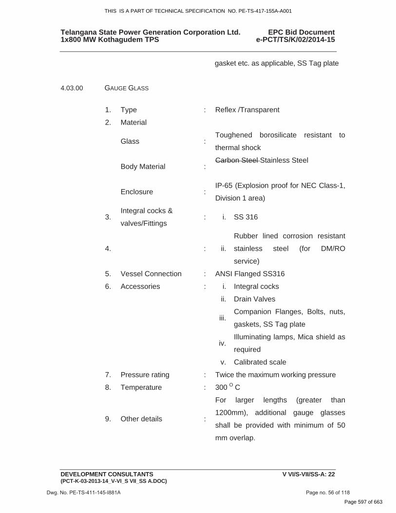
4.03.00 GAUGE GLASS
1. Type : Reflex /Transparent
2. Material
Glass : Toughened borosilicate resistant to
thermal shock
Body Material : Carbon Steel Stainless Steel
Enclosure : IP-65 (Explosion proof for NEC Class-1,
Division 1 area)
3. Integral cocks &
valves/Fittings : i. SS 316
4. : ii.
Rubber lined corrosion resistant
stainless steel (for DM/RO
service)
5. Vessel Connection : ANSI Flanged SS316
6. Accessories : i. Integral cocks
ii. Drain Valves
iii.Companion Flanges, Bolts, nuts,
gaskets, SS Tag plate
iv.Illuminating lamps, Mica shield as
required
v. Calibrated scale
7. Pressure rating : Twice the maximum working pressure
8. Temperature : 300 O C
9. Other details :
For larger lengths (greater than
1200mm), additional gauge glasses
shall be provided with minimum of 50
mm overlap.
Dwg. No. PE-TS-411-145-I881A Page no. 56 of 118
THIS IS A PART OF TECHNICAL SPECIFICATION NO. PE-TS-417-155A-A001
Page 597 of 663
Telangana State Power Generation Corporation Ltd. EPC Bid Document 1x800 MW Kothagudem TPS e-PCT/TS/K/02/2014-15
DEVELOPMENT CONSULTANTS V VI/S-VII/SS-A: 23 (PCT-K-03-2013-14_V-VI_S VII_SS A.DOC)
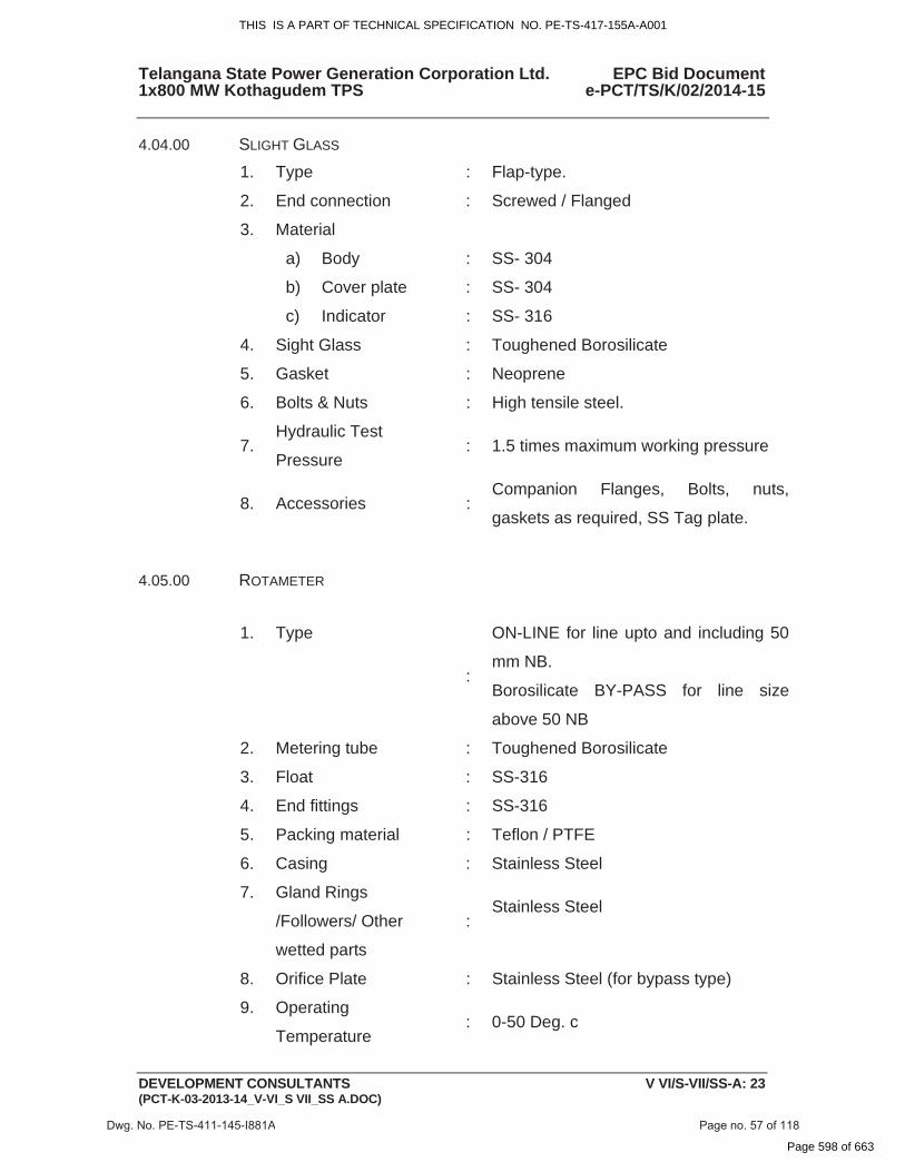
4.04.00 SLIGHT GLASS
1. Type : Flap-type.
2. End connection : Screwed / Flanged
3. Material
a) Body : SS- 304
b) Cover plate : SS- 304
c) Indicator : SS- 316
4. Sight Glass : Toughened Borosilicate
5. Gasket : Neoprene
6. Bolts & Nuts : High tensile steel.
7. Hydraulic Test
Pressure : 1.5 times maximum working pressure
8. Accessories : Companion Flanges, Bolts, nuts,
gaskets as required, SS Tag plate.
4.05.00 ROTAMETER
1. Type
:
ON-LINE for line upto and including 50
mm NB.
Borosilicate BY-PASS for line size
above 50 NB
2. Metering tube : Toughened Borosilicate
3. Float : SS-316
4. End fittings : SS-316
5. Packing material : Teflon / PTFE
6. Casing : Stainless Steel
7. Gland Rings
/Followers/ Other
wetted parts
: Stainless Steel
8. Orifice Plate : Stainless Steel (for bypass type)
9. Operating
Temperature : 0-50 Deg. c
Dwg. No. PE-TS-411-145-I881A Page no. 57 of 118
THIS IS A PART OF TECHNICAL SPECIFICATION NO. PE-TS-417-155A-A001
Page 598 of 663