Embed Size (px)
Citation preview
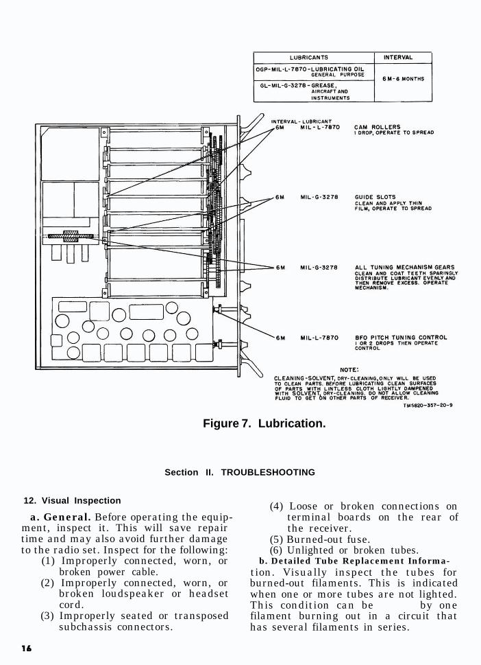
Figure 7. Lubrication.
Section II. TROUBLESHOOTING
12. Visual Inspection
a. General. Before operating the equip-ment, inspect it. This will save repairtime and may also avoid further damageto the radio set. Inspect for the following:
(1) Improperly connected, worn, orbroken power cable.
(2) Improperly connected, worn, orbroken loudspeaker or headsetcord.
(3) Improperly seated or transposedsubchassis connectors.
(4) Loose or broken connections onterminal boards on the rear ofthe receiver.
(5) Burned-out fuse.(6) Unlighted or broken tubes.
b. Detailed Tube Replacement Informa-tion. Visually inspect the tubes forburned-out filaments. This is indicatedwhen one or more tubes are not lighted.This condition can be caused by onefilament burning out in a circuit thathas several filaments in series.
(1) All filaments, except the four con-nected directly across the 25.2-volt filament supply, are connectedin series circuits which includetwo, three, or four filaments.
(2) In a series circuit, an open fil-ament in one stage will causeanother stage to appear defective.Tubes V605, V606, V801, andV802,oven heaters HR401, HR701, andHR901, and indicating lamps 1101and 1102 are connected directlyacross the 25.2-volt filament sup-ply. Cold-cathode, gas-filledtubesV608 and V609, also known asglow-discharge voltage regula-tors. do not require heated fil-aments.
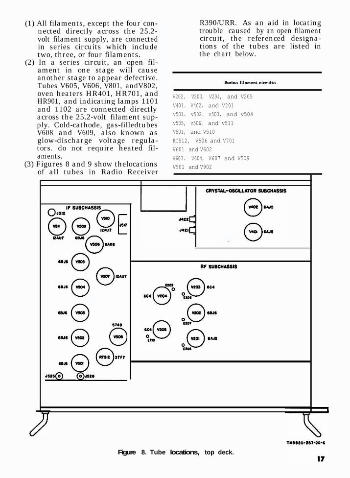
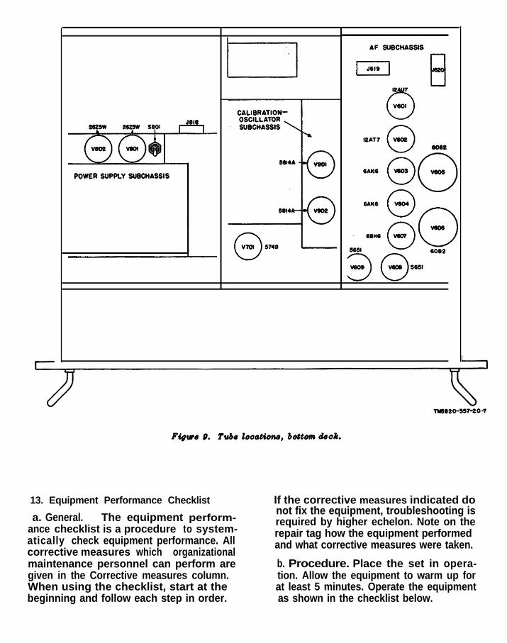
(3) Figures 8 and 9 show thelocationsof all tubes in Radio Receiver
c
R390/URR. As an aid in locatingtrouble caused by an open filamentcircuit, the referenced designa-tions of the tubes are listed inthe chart below.
V202. V203, V204, and V205V401. V402, and V201v501. v502. v503. and v504v505, v506, and v511V501, and V510RT512, V506 and V701V601 and V602V603. V604, V607 and V509V901 and V902
Figure 8. Tube locations, top deck.
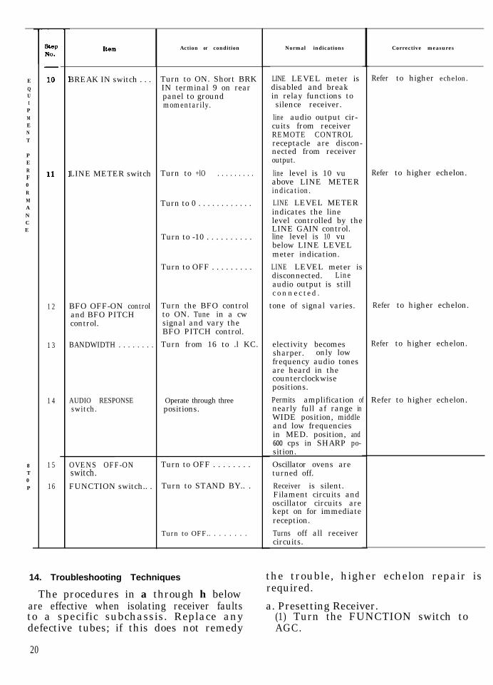
13. Equipment Performance Checklist If the corrective measures indicated do
a. General. The equipment perform-not fix the equipment, troubleshooting is
ance checklist is a procedure to system-required by higher echelon. Note on the
atically check equipment performance. Allrepair tag how the equipment performed
corrective measures which organizationaland what corrective measures were taken.
maintenance personnel can perform are b. Procedure. Place the set in opera-given in the Corrective measures column. tion. Allow the equipment to warm up forWhen using the checklist, start at the at least 5 minutes. Operate the equipmentbeginning and follow each step in order. as shown in the checklist below.
18

c. Checklist.
prEPARAt0RY
:uIPMENT
PERF0RMANCE
%JNO.
1 FUNCTION switch.. Turn to AGC . . . . . . . . .
2 MEGACYCLE Set to each band, in Normal signal outputCHANGE control. turn. on each band.
3 MLGCYCLECHANGE control.
Tune across a band...
4 ANT. TRIM control. Rotate control . . . . . . . .
5 LOCAL GAIN Rotate control in eithercontrol. direction.
6 LINE GAIN control . Rotate control in eitherdirection.
7
8
RF GAIN control.. . Rotate control . . . . . . . .
FUNCTION switch.. Turn to MGC . . . . , . . . .
Turn to AGC and tunethrough several dif-ferent signals.
Turn to CAL, and thenoperate the KILO-CYCLE CHANGE con-trol.
Turn to SQUELCH andthen operate theKILOCYCLE CHANGEcontrol.
Return FUNCTIONswitch to AGC andRF GAIN control to10 at completion ofthis check.
9 LIMITER control. . . Turn clockwise . . . . . . .
Item Normal indications
Dial lamp lights . . . . . .
Rushing noise or sig-nal heard in speakeror headset.
Signals. received,CARRIER LEVELmeter indicatesstrength of signal.
Obtain peak indicationon CARRIER LEVELmeter for each band.
Volume at loudspeakerincreases or de-creases.
Output level to 600-ohm line or headsetand LINE LEVELmeter increases ordecreases.
Audio output andCARRIER LEVELmeter Indication in-creases or decreases.
with no signal input,noise level should in-crease and CARRIERLEVEL meter doesnot indicate.
Output volume nearlyconstant.
Deflection on CARRIERLEVEL meter at each100-kc reading
No reception of noisewhile tuning betweenstations.
Noise peaks are re-duced in amplitude.
Check fuses FlOl and F102.
Check dial lamps.
Check power cable.
Rotate control several timestc clean contacts. De-termine which band orbands are inoperativethen check crystal used onthe bands (para 16).
Higher echelon repair re-quired.
Check antenna connector.
Check V601. V602, andV603.
If headset level varies andpointer of meter is stick-ing, tap meter lightly.
If local output is satisfac-tory but line output isweak, higher echelon re-pair is required.
Check tubes V201 and V202.
Check tubes V509, V510,and V511.
Reset ANT. TRIM control.Check tubes V9Ol andV902.
If noise is high, turn theRF GAIN control counter-:clockwise until the squelchcircuit is effective enoughto reduce the noise.Check V601.
Check tubes V507 and V510.
19
EQUIPMENT
PERF0RMANCE
8T0P
1 2
1 3
1 4
1 5
16
BREAK IN switch . . .
LINE METER switch Turn to +lO . . . . . . . . .
BFO OFF-ON controland BFO PITCHcontrol.
BANDWIDTH . . . . . . . . Turn from 16 to .l KC.
AUDIO RESPONSE Operate through threeswitch. positions.
OVENS OFF-ONswitch.FUNCTION switch.. .
Action or condition Normal indications Corrective measures
Turn to ON. Short BRK LINE LEVEL meter isIN terminal 9 on rear disabled and breakpanel to ground in relay functions tomomentarily. silence receiver.
Turn to 0 . . . . . . . . . . . .
Turn to -10 . . . . . . . . . .
Turn to OFF . . . . . . . . .
Turn the BFO controlto ON. Tune in a cwsignal and vary theBFO PITCH control.
Turn to OFF . . . . . . . .
Turn to STAND BY.. .
Turn to OFF.. . . . . . . .
Refer to higher echelon.
line audio output cir-cuits from receiverREMOTE CONTROLreceptacle are discon-nected from receiveroutput.
line level is 10 vuabove LINE METERindication.
Refer to higher echelon.
LINE LEVEL METERindicates the linelevel controlled by theLINE GAIN control.line level is 10 vubelow LINE LEVELmeter indication.
LINE LEVEL meter isdisconnected. Lineaudio output is stillconnected.
tone of signal varies. Refer to higher echelon.
electivity becomessharper. only lowfrequency audio tonesare heard in thecounterclockwisepositions.
Permits amplification ofnearly full af range inWIDE position, middleand low frequenciesin MED. position, and600 cps in SHARP po-sition.
Refer to higher echelon.
Refer to higher echelon.
Oscillator ovens areturned off.
Receiver is silent.Filament circuits andoscillator circuits arekept on for immediatereception.
Turns off all receivercircuits.
14. Troubleshooting Techniques the trouble, higher echelon repair is
The procedures in a through h below required.
are effective when isolating receiver faults a. Presetting Receiver.to a specific subchassis. Replace any (1) Turn the FUNCTION switch todefective tubes; if this does not remedy AGC.
20

(2) Turn the BANDWIDTH switch to16 KC.
(3) Turn the RF GAIN control to 10.(4) Turn the LOCAL GAIN control to
6.(5) Tune in a local station, or if no
station can be heard, listen to thenoise produced by the receiver.
(6) Turn the LINE METER switch to
(7) 0 adjust the LINE GAIN control fora midscale LINE LEVEL meterreading.
b. Power-Supply Subchassis Test . If alltubes light but the CARRIER LEVELmeter does not deflect and no sound orhum is heard in the headset or loud-speaker, check V801 and V802 (fig. 8)and fuses FlOl and F102 (TM-11-5820-357-10).c. Af Subchassis Test. (fig.8). Whilelistening to a station or to noise, groundDIODEpanel.
(1)
(2)
(3)
(4)
LOAD terminal 14 on the rear
The signal or noise at the localoutput and the LINE LEVEL meterindication should be greatly re-duced.If only the local output is reduced,check V602, V603, and the seatingof connector P120.If only the remote output is re-duced (LINE LEVEL meter pointermoves to the left), check V602,V604, and the seating of connectorP119.Remove tubes V507 and V510 and,with a pointed metallic probe thathas an insulated handle, touch tubesocket pin 1 of V510. A loud clickin the loudspeaker or headset in-dicates that the power supply andaudiofrequency (af) subchassis arefunctioning. Carefully replace thetubes after the test.
d. If Subchassis Test. (fig. 8). With thecontrols set as in a above, turn the BAND-WIDTH switch from 16 to each lower po-sition and listen to the signal or noise.
(1) The output should decrease ateach position, until it can hardlybe heard at the .l position.
(2) If there is little or no changeas the BANDWIDTH switch isturned, check V501 through V504and V506 through V509.
(3) Remove plug P226 (fig. 8) fromreceptacle 5526 and touch the con-tact of the receptacle with theprobe. A loud click from the loud-speaker or headset indicates thatthe af and if. circuits are function-ing. Carefully replace the plug.
e. Rf Subchassis Test. (fig. 8). Set thecontrols as in above. Start with themegacycle frequency indicator at 00 andturn the MEGACYCLE CHANGE controlthrough its range to the highest frequencyand listen to the noise in the headset orloudspeaker.
(1)
(2)
(3)
(4)
(5)
(6)
Across the tuning range, some ad-justment of the ANT. TRIM con-trol is necessary to produce max-imum noise.The noise at each detent positionshould be almost constant.There should be a pronouncedincrease in noise as the controlis seated in each detent.If the rf tuner does not pass thistest, check V201 through V204,V207 and V701.
Note. When V701 is replaced, the sub-chassis must be realigned at higher echelon.
If all bands except 00 through 08operate, change crystal Y201.Each crystal in crystal oven HR401operates a megacycle band or acombination of l-megacycle bands.To determine which crystal is de-fective, proceed as follows:
(a) Turn the MEGACYCLE CHANGEcontrol to each band to de-termine which bands are in-operative.
(b) Record the numbers of the de-fective bands.
(c) Match the combination of de-fective bands with the combi-nations listed in the chartbelow.
(d) Replace the defective crystal(fig. 10).
21

f. Noise at Grid Test Points. Set Mul-timeter AN/URM-105 to the highest re-sistance range. Connect one test lead tothe chassis and, in turn, touch the prodon the other lead to grid test points (fig.8 and 9) E210, E209, E208, E207, andE206in that order. A click should be heardeach time the prod touches the-test point.g. Calibration Oscillator Test. To testthe calibration oscillator, proceed as fol-lows :
(1)
(2)
(3)
(4)
(5)
Turn the FUNCTION switch toCAL.Turn the MEGACYCLE CHANGEcontrol to band 00.Tune the KILOCYCLE CHANGEcontrol through its entire range.Listen for a beat note at everylOO-Kilocycle (Kc) point as theKILOCYCLE CHANGE control istuned.If the calibrator fails to operate,make the following tests in theorder indicated:
Megacycle band affected Crystal in use
00, 17 Y40101, 18 Y40202, 08, 19, 30 Y40303, 20 Y40404, 09, 21 Y40505, 22 Y40606, 10, 23 Y40707, 15, 24 Y408II, 25 Y409i2, 27 Y41013, 29 Y41114, 31 Y41216 Y41326 Y41428 Y415
(a) Check V205 and V206 (fig. 8).(b) Replace Y203.(c) If the fault cannot be remedied
by this procedure, higher eche-lon repair is required.
h. Antenna Circuit Test. Rotate theANT. TRIM control. The CARRIER LEVELmeter should peak at one particular point.
(1) Disconnect the antenna and groundANTENNA J107 UNBALANCEDWHIP connector (TM 11-5820-357-10). A click should be heard andthe noise should drop sharply.
(2) Ground both contacts of ANTENNA. .5108 BALANCED 125 OHM con-nector. A click should be heardand the noise should drop sharply.
(3) If the receiver does not pass thistest, check the connectors on theantenna relay box.
15. Tube-Replacement Techniques
a. Isolate the trouble to a specific sub-chassis of the receiver (para 14).
b. Inspect all interior cable connectorsfor proper seating before removing a tube.
c. Substitute a new tube for an originalone. If no change is apparent in the opera-tion of the receiver, replace the new tubewith the original. Check each original tubeuntil the equipment becomes operative oruntil all suspected tubes have been tested.
(1)
(2)
(3)
(4)
Some circuits, such as oscillatorcircuits (V206, V207, V401, V505,and V701 (fig. 8 and 9))) may func-tion with one tube and not another,even though both tubes are new.If a replacement tube soonbecomesdefective, higher echelon repair isrequired.If tube substitution does not correctthe trouble, be sure that the orig-inal tubes are in the original sock-ets before forwarding the defectivereceiver for higher echelon repair.If another receiver of the same typeis available, refer to the instruc-tions in b below.
d. Discard tubes only in the cases givenin (1) and (2) below. Do not discard themmerely because they meet or are slightlyabove the lowest acceptable value listed inthe tube tester chart. Do not discardtubesmerely because they have been used forsome time. Satisfactory operation in thereceiver is the final proof of tube quality.
(1) Discard a tube when a tube testeror other instrument shows the tubeto be defective.
(2) Discard a tube when the defect,such as a broken glass envelope ora broken connecting pin can beseen.
22
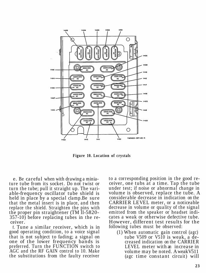
Figure 10. Location of crystals
e. Be careful when with drawing a minia-ture tube from its socket. Do not twist orturn the tube; pull it straight up. The vari-able-frequency oscillator tube shield isheld in place by a special clamp.Be surethat the metal insert is in place, and thenreplace the shield. Straighten the pins withthe proper pin straightener (TM ll-5820-357-10) before replacing tubes in the re-ceiver.f. Tune a similar receiver, which is in
good operating condition, to a voice signalthat is not subject to fading; a signal onone of the lower frequency bands ispreferred. Turn the FUNCTION switch toAGC and the RF GAIN control to 10. Makethe substitutions from the faulty receiver
to a corresponding position in the good re-ceiver, one tubs at a time. Tap the tubeunder test; if noise or abnormal change involume is observed, replace the tube. Aconsiderable decrease in indication on theCARRIER LEVEL meter, or a noticeabledecrease in volume or quality of the signalemitted from the speaker or headset indi-cates a weak or otherwise defective tube.However, different test results for thefollowing tubes must be observed:
(1) When automatic gain control (agc)tube V509 or V510 is weak, a de-creased indication on the CARRIERLEVEL meter with an increase involume may be noted. A weakV511(agc time constant circuit) will
23
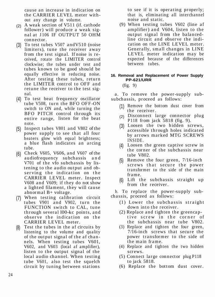
(2)
(3)
(4)
(5)
(6)
(7)
(8)
24
cause an increase in indication onthe CARRIER LEVEL meter with-out any change in volume.A weak section of V511 (if. cathodefollower) will produce a weak sig-nal at J106 IF OUTPUT 50 OHMconnector.To test tubes V507 andV510 (noiselimiters), tune the receiver awayfrom the test signal. If noise is re-ceived, rotate the LIMITER controlclockwise; the tubes under test andtubes known to be good should beequally effective in reducing noise.After testing these tubes, returnthe LIMITER control to OFF andretune the receiver to the test sig-nal.To test beat frequency oscillatortube V508, turn the BFO OFF-ONswitch to ON and, while turning theBFO PITCH control through itsentire range, listen for the beatnote.Inspect tubes V801 and V802 of thepower supply to see that all fourheaters glow with equal brightness;a blue flash indicates an arcingtube.Check V605, V606, and V607 of theaudiofrequency subchassis andV701 of the vfo subchassis by lis-tening to the audio output and ob-serving the indication on theCARRIER LEVEL meter. InspectV608 and V609; if they do not showa lighted filament, they will causeabnormal B+ voltage.When testing calibration circuittubes V901 and V902, turn theFUNCTION switch to CAL, tunethrough several l00-kc points, andobserve the indication on theCARRIER LEVEL meter.Test the tubes in the af circuits bylistening to the volume and qualityof the output signal of the af chan-nels. When testing tubes V601,V602, and V603 (local af amplifier),listen to the output signal of thelocal audio channel. When testingtube V601, also test the squelchcircuit by tuning between stations
to see if it is operating properly;that is, eliminating all interchannelnoise and static.
(9) When testing tubes V602 (line afamplifier) and V604, listen to theoutput signal from the balanced-line circuit and observe the indi-cation on the LINE LEVEL meter.Generally, small changes in LINELEVEL meter indication may beexpected because of the differencesbetween tubes.
16. Removal and Replacement of Power SupplyPP-621/URR
(fig. 9)
a. To remove the power-supply sub-subchassis, proceed as follows:
(1)
(2)
(3)
(4)
(5)
(6)
Remove the bottom dust cover fromthe receiver.Disconnect large connector plugP118 from jack 5818 (fig. 9).Loosen the two hidden screws,accessible through holes indicatedby arrows marked MTG SCREWSINSIDE.Loosen the green captive screw inthe corner of the subchassis neartube V802.Remove the four green, 7/16-inchscrews that secure the powertransformer to the side of the mainframe.Lift the subchassis straight upfrom the receiver.
b. To replace the power-supply sub-chassis, proceed as follows:
(1) Lower the subchassis straightdown into the receiver.
(2) Replace and tighten the greencap-tive screw in the corner ofthe subchassis near tube V802.
(3) Replace and tighten the four green,7/16-inch screws that secure thepower transformer to the side ofthe main frame.
(4) Replace and tighten the two hiddenscrews.
(5) Connect large connector plug P118to jack 5818.
(6) Replace the bottom dust cover.
Note. Except for installations where ex-treme dust conditions exist, the bottom andtop dust covers will not be used.
17. Removal and Replacement of Pilot Lamps
For location of pilot lamps, refer toTM11-5820-35’7-10.
a. Removal.(1) Remove the four Phillips screws
from the corners of the frequency-indicator window.
(2) Move the frequency-indicator win-dow a f ew inches f rom thefront panel. Its connecting wireswill hold it in position.
(3) Remove the defective pilot lamp.b. Replacement.
(1) Insert the new pilot lamps.(2) Place the frequency-indicator win-
dow in position; line up the fourscrew holes.
(3) Replace and tighten the four Phil-lips screws.
25
CHAPTER 4
SHIPMENT AND LIMITED STORAGE
18. Disassembly
The following instructions are recom-mended as a guide for preparing the re-ceiver for transportation and storage.a. Disconnect the antenna lead-in cable.b. Disconnect the power cable from theac outlet, and from the back of the receiver.Neatly coil the power cable and secure withtwo lengths of pressure-sensitive tape.c. Remove all connections to the termi-nal boards on the rear panel of the re-ceiver .
d. Unplug the headphone cord from thePHONES jack on the front panel.
e. If dust covers and tube shields wereremoved from the receiver for ventila-tion purposes, reinstall them before pack-ing. ,
19. Repacking for Shipment or Limited Storage
-The exact procedure for repacking de-pends on the material available and theconditions under which the receiver is tobe shipped or stored. Follow the procedurein through below whenever possible, aswell as the information concerning theoriginal packaging (para 3 and fig. 1).a. Material Requirements.
Material Quantity .
Fiberboard, corrugated, single-faced. 40 sq ft
Tape, water-resistant, pressure-sensitive, 3-inch. 16 ft
Steel strapping, 5/8-inch by 0. 020-inch. 13 ft
Wooden shipping crate, 22-l/4 x 20-l/2 x 14-3/4. 1
b. Packaging.(1)
(2)
(3)
Enclose each technical manual in aclose-fitting paper envelope. Sealthe seams of the envelope withwater-resistant, pressure-sensi-tive tape.Cushion the receiver on all sur-faces with pads made of single-faced corrugated fiberboard, inorder to absorb shocks that mightbe caused by handling and shipping.Securely pack the running spares.
(2)
c . Packing.
(3)
(4)(5)
(1) Line the wooden crate with enoughmaterial so that it may be sealed
(6)
over the receiver when it is placedin the crate.Place the packaged receiver, thepackaged manuals, and the runningspares in the crate.Seal the fiberboard carton with thewater-resistant, pressure-sensi-tive tape.Nail the top of the wooden crate.
On intertheater shipments only,apply two bands of steel strapping.
Mark the shipping crate accordingto the requirements of AR 220-10.
26

APPENDIX IREFERENCES
--------------------------------------------------------------------------------------------------------------------- Following is a list of references applicable and available to the unit repairman of Radio Receiver R-390/URR.AR 220-10 Preparation for Overseas Movement of Units (POM).AR 750-5 Maintenance Responsibilities and Ship Operation.DA Pam 108-l Index of Army Motion Pictures, Film Strips, Slides, and
Phono Recordings.DA Pam 310-4 Index of Technical Manuals, Technical Bulletins,
Supply Bulletins, Lubrication Orders, and ModificationWork Orders.
FM 21-5 Military Training.FM 21-6 Techniques of Military Instruction.FM 21-30 Military Symbols.SR 320-5 Dictionary of United States Army Terms.SR 320-50 Authorized Abbreviations and Brevity Codes.TM 11-666 Antennas and Radio Propagation.TM 11-2629 Antenna Kit for Double-Doublet Receiving Antenna
(Drawing ES-E-276-F).TM 1 l-5820-357-10 Operators Manual, Radio Receiver R -390/URR.TM 1 l-6625-203-12 Operation and Organizational Maintenance: Multimeter
AN/URM-105, including Multimeter ME-77/U..TM 1 l-6625-274-12 Operator’s and Organizational Maintenance Manual:
Test Sets, Electron Tube TV-7/U, TV-7A/U, TV-7B/U, and TV-7D/U.
By Order of the Secretary of the Army :
Official :
G. H. DECKER,General, United States Army,
Chief of Staff
R. V. LEE,Major General, United States Army,
The Adjutant General.
Distribution:
Active Army:
To be distributed in accordance with DA Form 12-7 requirements for TM 11 series (Unclas)plus the following:
USASA (2)CNGB (1 )Tech Stf, DA (1) exceptCSigO ( 1 8 )DASA (6 )ARADCOM (2)ARADCOM Rgn (2)MDW (1)Seventh US Army (2)EUSA (2 )USASCS (Ft Monmouth) (109)Units org under fol TOE:
(2 each UNOINDC)1 l-711-16
1 l-321 l-5711-851 l-8611-9811-11711-15511-600 A A - A E (4)1 l-5571 l-5871 l-5921 l-69732-5 132-5632-57
NG: State AG (3) Units same as Active Army except allowance is one copy to each unit.USAR: None.For explanation of abbreviations used, see AR 320-50.
28
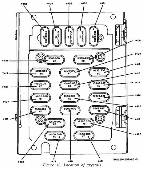
Figure 10. Location of crystals