Embed Size (px)
Citation preview

Section 3Crane control unit
Driver seat
Portable control unit
Control pedestal for offshore

Your tool for finding industrial controllers for cranes, electro-hy-draulic systems, floor conveyors, industrial applications, ships, rail vehicles, and construction machinery of any kind, joysticks and masterswitches with electronic interface adjustment for all machines matching our product portfolio. Take advantage of our fold-out order tool on this page and the detailed tables of contents at the beginning of each position.
Tool for Designers, Engineers and Purchasing Agents
Product range
3Crane control unit
Driver seat
Portable control unit
Control pedestal for offshore
As of2015

Product Portfolio
Multi-axis controller, double-handle controller, control switch (master-switch), gear limit switch for hoisting, electro-hydraulic application, material-handling technology and remote control
Geared limit switch for joisting equipment
Complete crane control unit, portable control unit, pendant control unit, including wiring for all types of cranes, vehicles and industrial applications
Operating panels for construction machinery, industrial applications, vehicles and harvesting machines
Control pedestals, ship-operating transmitters, sensor units and actual-value transmitters for ship drives
Pedal controllers for welding machines, road and rail vehicles
Master controllers, panels and control stations for rail vehicles
Displays for forklifts and construction machinery
Proportional control electronics for solenoid valves
Interface electronics with digital and analog outputs matching our controllers
Interface electronics with Profibus interface or CAN-bus interface matching our controllers (input/output cards)
DC controllers, selector switches (signal controllers) for high-voltage systems
Customized solutions for operating devices and electronic units for any type of machinery and vehicles
Gessmann is an international market leader. Our success in the market is based upon our decisive focus on innovative product development and the highest possible standards when it comes to quality. Our product range includes:
Management certification:
Contents
Multi-axis controller V6 / VV6 S. 1-5
V11 S. 6-9
V8 / VV8 S. 10-13
V85 / VV85 S. 14-22
V24 S. 23-26
V25 S. 27-32
V14 S. 33-36
V20 S. 37-38
V22 S. 39-40
V23 S. 41-42
V21 S. 43-44
Double-handle controller D64 / DD64 S. 45-49
D8 S. 50-53
D85 S. 54-59
D3 S. 60-64
Single-axis controller S1 S. 65-67
S11 S. 68-71
S14 S. 72-74
S2 / SS 2 / S21 S. 75-79
S22 / SS22 S. 80-83
S23 S. 84-86
S26 S. 87-90
S27 S. 91-94
S3 S. 95-98
S9 S. 99-100
Control switch N6 S. 101-103
N9 S. 104-105
Standard contact-arrangement S. 106-107
Ordering information S. 108-112
Technical data S. 113-114
Potentiometer S. 115
HG 1 S. 116-117
OEC 2 S. 118-120
OEC 4 S. 121
Electronic control unit S. 122-123
MATRIX grip S. 124
Hall-push button S. 125-127
Palm grip B1 S. 128-129
B2 S. 130-131
B3 S. 132-134
B5 S. 135-136
B6 S. 137-138
B7 / B8 S. 139-140
B9 S. 141-142
B10 S. 143-144
B14 / B15 S. 145-146
B20 S. 147-148
B22 S. 149-150
B23 S. 151-152
B24 S. 153-154
B25 S. 155-156
B28 S. 157-158
B29 S. 159-160
Housing S. 161-162
Crane control unit KST 4 S. 163-165
KST 5 S. 166-168
KST 6 S. 169-171
KST 7 / KST 75 S. 172-174
KST 8 S. 175-177
KST 85 S. 178-179
KST 10 S. 180-182
KST 19 S. 183-185
Driver seat KFS 2 S. 186-187
KFS 4 S. 188-189
KFS 82 S. 190-191
KFS 9 S. 192-193
KFS 10 S. 194-195
KFS 11 S. 196-197
KFS 12 S. 198-199
Portable control unit TS 1 S. 200-202
TS 2 S. 203-205
Control pedestal for offshore U 22/32 S. 206-208
U 23/23 S. 209-211
Naval cruise controller AZ 1 S. 212-213
Pedal-controller P7 / PP7 S. 214-215
P8 / PP8 S. 216-217
P10 / P11 / P12 S. 218-219
Gear limit switch GE 1/2 S. 220-222
DC-contact SO / SS S. 223-224
Signal-cam controller NU 1 S. 225-227

page 163
3
Crane control unit KST 4 swiveling
Technical details may vary based on configuration or application! Technical data subject to change without notice!
The KST 4 is an ergonomically designed swiveling crane control chair which provides a high degree of comfort.
Equipment boxes: The sheet steel equipment boxes are vertically and horizontally adjusted. The arrangement of the joysticks, indicators and control devices is customised according to customer specifications. Cabling is run through aduct in the cross-member. (Terminal block) Special boxes available upon request.
Driver seat: As standard the KST 4 is fitted with a KFS 6 seat. The seat itself is fitted with a hydraulic vibration absorption system complete with weight adjustment to ensure that the comfort level is fitted with armrests and a headrest. There is the option to have the seat covered with air-permeable artificial leather.
Cross-member with swivel base: The cover of the sheet steel cross-member including the driver’s seat is forward foldable. Thereby all wirings, terminals and bushings are easily accessible during commissioning and maintenance. Swivel base has zero-clearance bearing and can be locked by a friction brake.
Surface treatment: Base coat and textured varnish Standard colour RAL 9011 black
KST 41 - 3 - M1 - F1 - LK / KFS 11 / V64 / V64.1 / KL / X
Basic unit
KST 41 With equipment boxes 160x420 mm
KST 42 With equipment boxes 200x420 mm
Base unit
1 Swiveling 180° left, 90° right with friction brake
2 Electric swiveling 180° left, 90° right
3 Not swiveling
4 Without base frame
Attachment
M1 Monitor mounting with monitor housing
M2 Monitor mounting with monitor mounting braket
M3 Monitor mounting without monitor housing/ -mounting braket
F1 Footrest mounted dispatch 1 KBF/433
H Heater 2x2 kW with ventilator
LK Plate for horizontal manual adjustment of crane control unites +/- 250 mm
Driver seat
KFS 11* (included in the delivery!)
KFS 9*
KFS 10*
KFS 12*
*Description see driver seat page 186
Example

page 164
V20
15/1
10.
02.2
015
3
Crane control unit KST 4 swiveling
Technical details may vary based on configuration or application! Technical data subject to change without notice!
KST 41 - 3 - M1 - F1 - LK / KFS 11 / V64 / V64.1 / KL / X
Mountig for equipment boxes
V... Multi-axis controller (see page 1)
S... Single-axis controller (see page 65)
D... Double-handle controller (see page 45)
N... Control-switch (see page 101)
... More command and indicating devices (see page 162)
Wiring
KL Without wiring, each terminal block built in each terminal
KLV On terminal block 4 qmm with single wire 1 qmm each terminal
KLV On SPS (SPS provision) with single wire 1 qmm each terminal
KLVA External wiring single wire highly flexible 1,5 qmm 5 m long, each terminal
Special model
X Special / customer-specific
X� Special painted

page 165
3
Crane control unit KST 4 swiveling
Technical details may vary based on configuration or application! Technical data subject to change without notice!
510
±30
* 1
140
±30
*
A A 580
B
220
590
84
550
wei
ght
load
ed
KFS 11optionalKFS 12
640 ±25 *
40° 480 ±25 *
swing-upequipment
boxes 55°
10°
5°
370 ±125 *
Horizontal adjustmentseat with equipment boxes
100 100
Horizontal adjustmentof equipment boxes
25 25
Inclination adjustmentof equipmentboxes
420
C
90° 180°
2
1
43
6
5
87
Direction of view
leftbox
rightboxseat
14
300
240
Floor mounting
cable inlet Ø100
848
with heating
2 / 041
* adjustable
Type Dim. A Dim. B Dim. C
KST 41 160 900 max. 670min. 570
KST 42 200 980 max. 700min. 600

page 166
V20
15/1
10.
02.2
015
3
Crane control unit KST 5 swiveling
Technical details may vary based on configuration or application! Technical data subject to change without notice!
The KST 5 is an ergonomically designed swiveling crane control chair which provides a high degree of comfort.
Equipment boxes: The equipment boxes are made from sheet steel and as standard have a hinged lid with locking feature. This allows for easy inspection and maintenance. The side of the equipment boxes is as standard fitted with an inspection plate which again is lockable. The arrangement of the joystick, indicators and control devices is cutomised according to customer specifications. This combined with the custom sized and pro-filed equipment boxes that are available means that the KST 5 is very flexible and customisable solution.
Driver seat: As standard the KST 5 is fitted with a KFS 6 seat. The seat itself is fitted with a hydraulic vibration absorption system complete with weight adjustment to ensure that the comfort level is fitted with armrests and a headrest. There is the option to have the seat covered with air-permeable artificial leather.
Cross-member with swivel base: The cover of the sheet steel cross-member including the driver’s seat is forward foldable. Thereby all wirings, terminals and bushings are easily accessible during commissioning and maintenance. Swivel base has zero-clearance bearing and can be locked by a friction brake.
Surface treatment: Base coat and textured varnish Standard colour RAL 9011 black
KST 51 - 3 - M1 - F1 - LK / KFS 11 / V64 / V64.1 / KL / X
Basic unit
KST 51 With equipment boxes 200x580 mm
KST 52 With equipment boxes 270x580 mm
KST 54 With equipment boxes 320x580 mm
Special boxes for demand!
Base unit
1 Swiveling 180° left, 90° right with friction brake
2 Electric swiveling 180° left, 90° right
3 Not swiveling
Attachment
M1 Monitor mounting with monitor housing
M2 Monitor mounting with monitor mounting braket
M3 Monitor mounting without Monitor housing/-mounting braket
F1 Footrest KBF/433
H Heater 2x2 kW with ventilator 240V AC
LS Plate for horizontal manual adjustment for control units +/- 75 mm
LK Plate for horizontal manual adjustment for control units +/- 250 mm
Label without engraving for multi-axis-/ single-axis controller
Label with engraving for multi-axis-/ single-axis controller
Example

page 167
3
Crane control unit KST 5 swiveling
Technical details may vary based on configuration or application! Technical data subject to change without notice!
KST 51 - 3 - M1 - F1 - LK / KFS 11 / V64 / V64.1 / KL / X
Driver seat
KFS 11* (included in the delivery!)
KFS 9*
KFS 10*
KFS 12*
*Description see driver seat page 186
Mounting for equipment boxes
V... Multi-axis controller (see page 1)
S... Single-axis controller (see page 65)
D... Double-handle controller (see page 45)
N... Control-switch (see page 101)
... More command and indicating devices (see page 162)
Wiring
KL Without, but terminal block built each terminal
KLV On terminal block 4 qmm with single wire 1 qmm each terminal
KLV On SPS (SPS provision) with single wire 1 qmm each terminal
KLVA External wiring single wire highly flexible 1,5 qmm 5 m long, each terminal
Special model
X Special / customer-specific
X1 Special painted

page 168
V20
15/1
10.
02.2
015
3
V20
13/1
20.
08.2
013
Crane control unit KST 5 swiveling
Technical details may vary based on configuration or application! Technical data subject to change without notice!
360
8
4
544
114
0 ±3
0*
510
±30
*
600 990
A A
B
600
wei
ght l
oade
d
KFS 11optionalKFS 12
90
25
580 418
1200 ( traverse path 500 )
40°
Horizontaladjustment
of control unit250 250
Manualadjustmentof foot rest
15
15
Horizontal adjustment
of seat100 100
C
90° 180°
2
1
43
6
5
87
Direction of view
left box
rightbox
seat
14
300
240
Floor mounting
cable inlet Ø100
600
550
130
120
0
630
115
0
14
Floor mounting
2/0512014
* adjustable
Type Dim. A Dim. B Dim. C
KST 51 200 1000 580
KST 52 270 1140 640
KST 54 320 1240 690

page 169
3
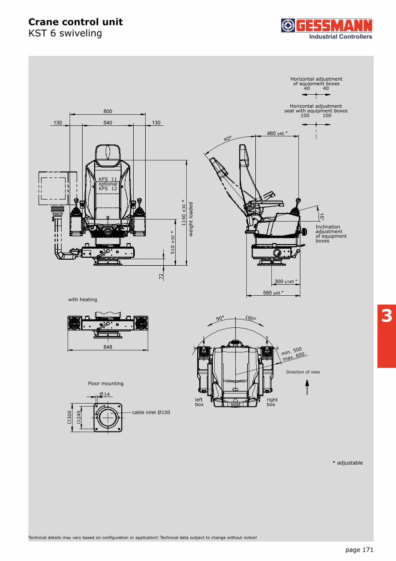
Crane control unit KST 6 swiveling
Technical details may vary based on configuration or application! Technical data subject to change without notice!
The KST 6 is an ergonomically designed swiveling crane control chair which provides a high degree of comfort.
Equipment boxes: The sheet steel equipment boxes are vertically and horizontally adjusted. The arrangement of the joysticks, indicators and control devices is customised according to customer specifications. Cabling is run through adcut in the cross-member. (Terminal block)
Driver seat: As standard the KST 6 is fitted with a KFS 6 seat. The seat itself is fitted with a hydraulic vibration absorption system complete with weight adjustment to ensure that the comfort level is fitted with armrests and a headrest. There is the option to have the seat covered with air-permeable artificial leather.
Cross-member with swivel base: The cover of the sheet steel cross-member including the driver’s seat is forward foldable. Thereby all wirings, terminals and bushings are easily accessible during commissioning and maintenance. Swivel base has zero-clearance bearing and can be locked by a friction brake.
Surface treatment: Base coat and textured varnish Standard colour RAL 9011 black
KST 6 - 3 - M1 - F1 - LK / KFS 11 / V64 / V64.1 / KL / X
Basic unit
KST 6 With equipment boxes
Base unit
1 Swiveling 180° left, 90° right with friction brake
2 Electric swiveling 180° left, 90° right
3 Not swiveling
4 Without base frame
Attachment
M1 Monitor mounting with monitor housing
M2 Monitor mounting with monitor mounting braket
M3 Monitor mounting without monitor housing/-mounting braket
F1 Footrest KBF/433
H Heater 2x2 kW with ventilator
LK Plate for horizontal manual adjustment for control unites +/- 250 mm
Driver seat
KFS 11* (included in the delivery!)
KFS 9*
KFS 10*
KFS 12*
*Description see driver seat page 186
Example

page 170
V20
15/1
10.
02.2
015
3
Crane control unit KST 6 swiveling
Technical details may vary based on configuration or application! Technical data subject to change without notice!
KST 6 - 3 - M1 - F1 - LK / KFS 11 / V64 / V64.1 / KL / X
Mounting for equipment boxes
V... Multi-axis controller (see page 1)
S... Single-axis controller (see page 65)
D... Double-handle controller (see page 45)
N... Control-switch (see page 101)
... More command and indicating devices (see page 162)
Wiring
KL Without, but terminal block built each terminal
KLV On terminal block 4 qmm with single wire 1 qmm each terminal
KLV On SPS (SPS provision) with single wire 1 qmm each terminal
KLVA External wiring single wire highly flexible 1,5 qmm 5 m long each terminal
Special model
X Special / customer-specific
X� Special painted
page 171
3
Crane control unit KST 6 swiveling
Technical details may vary based on configuration or application! Technical data subject to change without notice!
72
510
±30
* 1
140
±30
*
130 130 540
800
wei
ght
load
ed
KFS 11optionalKFS 12
585 ±40 *
40°
15°
300 ±140 *
460 ±40 *
Horizontal adjustmentseat with equipment boxes
100 100
Horizontal adjustmentof equipment boxes
40 40
Inclination adjustmentof equipmentboxes
max. 600min. 500
90° 180°
2
1
43
6
5
87
Direction of view
left box
rightboxseat
14
300
240
Floor mounting
cable inlet Ø100
* adjustable
848
with heating
2 / 061

page 172
V20
15/1
10.
02.2
015
3
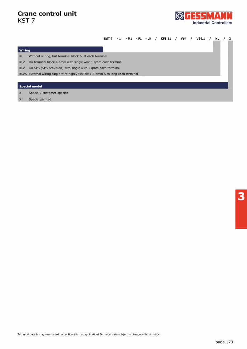
Crane control unit KST 7
Technical details may vary based on configuration or application! Technical data subject to change without notice!
The KST 7 is an ergonomically designed swiveling crane control chair which provides a high degree of comfort.
Equipment boxes: The equipment boxes are made from sheet steel and as standard have a hinged lid with locking feature. This allows for easy inspection and maintenance. The side of the equipment boxes is as standard fitted with an inspection plate which again is lockable. The arrangement of the joystick, indicators and control devices is cutomised according to customer specifications. This combined with the custom sized and pro-filed equipment boxes that are available means that the KST 7 is very flexible and customisable solution.
Driver seat: The tipped spring mounted seat KFS 4 is fit with an hydraulic vibration absorption system incl. weight adjustment. With the folding spring mounted seat you can also arrive your workplace in small cabins.
Base plate: The cran control unit is available with or without base plate.
Surface treatment: base coat and textured varnish Standard colour RAL 7032 pebble-grey
KST 7 - 1 / KFS 11 / V64 / V64.1 / KL / X
Basic unit
KST 7 with equipment boxes 290x500 mm
KST 75 with equipment boxes 210x500 mm
Special boxes for demand!
Base plate
1 With base plate prepare for driver seat KFS 4
2 With base plate prepare for driver seat KFS 2
3 With base plate with apron for driver seat KFS 9, KFS 11...
4 Without base plate
Driver seat
KFS 4* (included in the delivery!)
KFS 2*
KFS 11*
KFS 9*
*Description see driver seat page 186
Mounting for equipment boxes
V... Multi-axis controller (see page 1)
S... Single-axis controller (see page 65)
D... Double-handle controller (see page 45)
N... Control-switch (see page 101)
... More command and indicating devices (see page 162)
Example
page 173
3
Crane control unit KST 7
Technical details may vary based on configuration or application! Technical data subject to change without notice!
KST 7 - 1 - M1 - F1 - LK / KFS 11 / V64 / V64.1 / KL / X
Wiring
KL Without wiring, but terminal block built each terminal
KLV On terminal block 4 qmm with single wire 1 qmm each terminal
KLV On SPS (SPS provision) with single wire 1 qmm each terminal
KLVA External wiring single wire highly flexible 1,5 qmm 5 m long each terminal
Special model
X Special / customer-specific
X� Special painted

page 174
V20
15/1
10.
02.2
015
3
V20
13/1
20.
08.2
013
Crane control unit KST 7
Technical details may vary based on configuration or application! Technical data subject to change without notice!
290
320
45
30
20
300
25
245
9
30
570
650
...7
40
750
C
290 290 A
B
780
...9
90
X
KFS 2
Direction of view
250 250
375 375 62
1180
180
220
340
18
Base platefor KFS 4, 9
Cutting
250 250
300 300 62
1030
180
220
340
18
Base platefor KFS 2
Cutting
80
340
500
320
260...430
610...780
View X
Cutting 200x260
2/0712014
Without base plate
Type Dim. A Dim. B Dim. C
KFS 2 450 1030 50
KFS 4 600 1180 25
KFS 9 600 1180 25

page 175
3
Crane control unit KST 8 swiveling
Technical details may vary based on configuration or application! Technical data subject to change without notice!
The KST 8 is an ergonomically designed swiveling crane control chair which provides a high degree of comfort.
Equipment boxes: The sheet steel equipment boxes are vertically and horizontally adjusted. The arrangement of the joysticks, indicators and control devices is customised according to customer specifications. Cabling is run through aduct in the cross-member. (Terminal block) Special boxes available upon request.
Driver seat: As standard the KST 8 is fitted with a KFS 11 seat. The seat itself is fitted with a hydraulic vibration absorption system complete with weight adjustment to ensure that the comfort level is fitted with armrests and a headrest. There is the option to have the seat covered with air-permeable artificial leather.
Cross member with swivel base: The cover of the sheet steel cross-member including the driver’s seat is forward foldable. Thereby all wirings, terminals and bushings are easily accessible during commissioning and maintenance. Swivel base has zero-clearance bearing and can be locked by a friction brake.
Surface treatment: Base coat and textured varnish Standard colour RAL 9011 black
KST 8 - 3 - M1 - F1 - LK / KFS 11 / V64 / V64.1 / KL / X
Basic unit
KST 8 With equipment boxes
Base unit
1 Swiveling 180° left, 90° right with friction brake
2 Electric swiveling 180° left, 90° right
3 Not swiveling
4 Without base frame
Attachment
M1 Monitor mounting with monitor housing
M2 Monitor mounting with monitor mounting braket
M3 Monitor mounting without monitor housing/-mounting braket
F1 Footrest KBF/433
H Heater 2x2kW with ventilator
LK Plate for horizontal manual adjustment of control units +/- 250 mm
Driver seat
KFS 11* (included in the delivery!)
KFS 9*
KFS 10*
KFS 12*
*Description see driver seat page 186
Example

page 176
V20
15/1
10.
02.2
015
3
Crane control unit KST 8 swiveling
Technical details may vary based on configuration or application! Technical data subject to change without notice!
KST 8 - 3 - M1 - F1 - LK / KFS 11 / V64 / V64.1 / KL / X
Mounting for equipment boxes
V... Multi-axis controller (see page 1)
S... Single-axis controller (see page 65)
D... Double-handle controller (see page 45)
N... Control-switch (see page 101)
... More command and indicating devices (see page 162)
Wiring
KL Without wiring, but terminal block built each terminal
KLV On terminal block 4 qmm with single wire 1 qmm each terminal
KLV On SPS (SPS provision) with single wire 1 qmm each terminal
KLVA External wiring single wire highly flexible 1,5 qmm 5 m long each terminal
Special model
X Special / customer-specific
X� Special painted

page 177
3
Crane control unit KST 8 swiveling
Technical details may vary based on configuration or application! Technical data subject to change without notice!
72
510
±30
* 1
140
±30
*
130 130 580
840
wei
ght
load
edKFS 11optionalKFS 12
800 ±25 *
40° 470 ±25 *
swing-upequipment
boxes55°
10°
5°
531 ±125 *
Horizontal adjustmentseat with equipment boxes
100 100
Horizontal adjustmentof equipment boxes
25 25
Inclination adjustmentof equipmentboxes
max.780
min.660
90° 180°
2
1
43
6
5
87
Direction of view
leftbox
rightbox
seat14
300
240
Floor mounting
cable inlet Ø100
* adjustable
848
with heating
2 / 0812014

page 178
V20
15/1
10.
02.2
015
3
Crane control unit KST 85
Technical details may vary based on configuration or application! Technical data subject to change without notice!
The KST 85 is an ergonomically designed swiveling crane control chair which provides a high degree of comfort.
Equipment boxes: The sheet steel equipment boxes are vertically and horizontally adjusted. The arrangement of the joysticks, indicators and control devices is customised according to customer specifications. Cabling is run through aduct in the cross-member. (Terminal block) Special boxes available upon request.
Driver seat: The comfortable spring mounted seat KFS 85 with roller-bearing swivel systems.
Heating console: Cover with 2 steps heating (2x2 kW 400V AC) with integrated ventilator. The cover of the heating cover can be tilted forward to reach the terminal block of the heating and cable execution.
Surface treatment: Base coat and textured varnish Standard colour RAL 9011 black
KST 85 - M1 / KFS 82 / V64 / V64.1 / KL / X
Basic unit
KST 85 With heating in the apron
KST 87 With apron without heating
Attachment
M1 Monitor mounting with monitor housing
M2 Monitor mounting with monitor mounting braket
M3 Monitor mounting without monitor housing/-mounting braket
Driver seat
KFS 82* (included in the delivery!)
Mounting for equipment boxes
V... Multi-axis controller (see page 1)
S... Single-axis controller (see page 65)
D... Double-handle controller (see page 45)
N... Control-switch (see page 101)
.... More command and indicating devices (see page 162)
Wiring
KL Without wiring, but with terminal block built each terminal
KLV On terminal block 4 qmm with single wire 1 qmm each terminal
KLV On SPS (SPS provision) with single wire 1 qmm each terminal
KLVA External wiring single wire highly flexible 1,5 mm 5 m long each terminal
Special model
X Special / customer-specific
X� Special painted
Example

page 179
3
Crane control unit KST 85
Technical details may vary based on configuration or application! Technical data subject to change without notice!
130 130 560
820
595
±30
* 1
100
±30
*
wei
ght
load
ed
KFS 8
850 ±25 *
10°
5°
470 ±25 *
7,5° 20,5°
7x4° = 28°
306 ±75 *
Horizontal adjustmentof equipment boxes
25 25
Horizontal adjustmentseat with equipment boxes
75 75
Inclination adjustmentof equipmentboxes
90°
2
1
43
6
5
87
Direction of view
leftbox
rightboxseat
Swivelled one-sidedendpoints to lock
100
320
86 168,5 266,5
80
53
1
97
Floor mounting
* adjustable
Ø12x20
cable inlet Ø28
Middlepointseat
Fresh airopening
2 / 083

page 180
V20
15/1
10.
02.2
015
3
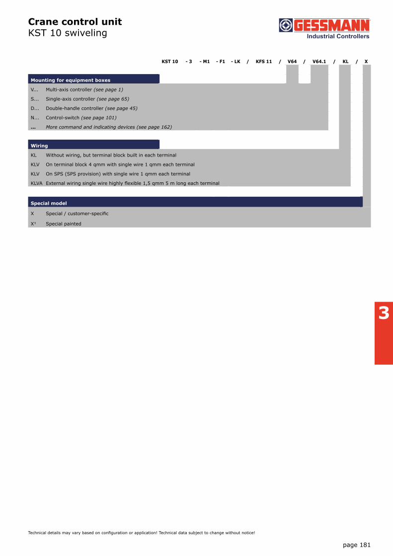
Crane control unit KST 10 swiveling
Technical details may vary based on configuration or application! Technical data subject to change without notice!
The KST 10 is an ergonomically designed swiveling crane control chair which provides a high degree of comfort.
Equipment boxes: The sheet steel equipment boxes are vertically and horizontally adjusted. The arrangement of the joysticks, indicators and control devices is customised according to customer specifications. Cabling is run through aduct in the cross-member. (Terminal block) Special boxes available upon request.
Driver seat: As standard the KST 10 is fitted with a KFS 11 seat. The seat itself is fitted with a hydraulic vibration absorption system complete with weight adjustment to ensure that the comfort level is fitted with armrests and a headrest. There is the option to have the seat covered with air-permeable artificial leather.
Cross-member with swivel base: The cover of the sheet steel cross-member including the driver’s seat is forward foldable. Thereby all wirings, terminals and bushings are easily accessible during commissioning and maintenance. Swivel base has zero-clearance bearing and can be locked by a friction brake.
Surface treatment: Base coat and textured varnish Standard colour RAL 9011 black
KST 10 - 3 - M1 - F1 - LK / KFS 11 / V85 / V85.1 / KL / X
Basic unit
KST 10 With equipment boxes
Base unit
1 Swiveling 180° left, 90° right with friction brake
2 Electric swiveling 180° left, 90° right
3 Not swiveling
4 Without base frame
Attachment
M1 Monitor mounting with monitor housing
M2 Monitor mounting with monitor mounting braket
M3 Monitor mounting without monitor housing/-mounting braket
F1 Footrest KBF/433
H Heater 2x2 kW with ventilator
LK Plate for horizontal manual adjustment of control units +/- 250 mm
Driver seat
KFS 11* (included in the delivery!)
KFS 9*
KFS 10*
KFS 12*
*Description see driver seat page 186
Example
page 181
3
Crane control unit KST 10 swiveling
Technical details may vary based on configuration or application! Technical data subject to change without notice!
KST 10 - 3 - M1 - F1 - LK / KFS 11 / V64 / V64.1 / KL / X
Mounting for equipment boxes
V... Multi-axis controller (see page 1)
S... Single-axis controller (see page 65)
D... Double-handle controller (see page 45)
N... Control-switch (see page 101)
... More command and indicating devices (see page 162)
Wiring
KL Without wiring, but terminal block built in each terminal
KLV On terminal block 4 qmm with single wire 1 qmm each terminal
KLV On SPS (SPS provision) with single wire 1 qmm each terminal
KLVA External wiring single wire highly flexible 1,5 qmm 5 m long each terminal
Special model
X Special / customer-specific
X� Special painted

page 182
V20
15/1
10.
02.2
015
3
V20
13/1
20.
08.2
013
Crane control unit KST 10 swiveling
Technical details may vary based on configuration or application! Technical data subject to change without notice!
max. 685min. 470
90° 180°
2
1
43
6
5
87
Direction of view
leftbox
right box
seat14
300
240
Floor mounting
cable inlet Ø100
* adjustable
473 ±25 *
440 ±125 *
707 ±25 *
40°
swing-upequipment
boxes 55°
10°
5°
Inclination adjustmentof equipmentboxes
Horizontal adjustmentseat with equipment boxes
100 100
Horizontal adjustmentof equipment boxes
25 25
848
with heating
72
510
±30
* 1
140
±30
*
130 510 130
770
KFS 11optionalKFS 12
2 / 101
wei
ght l
oade
d
page 183
3
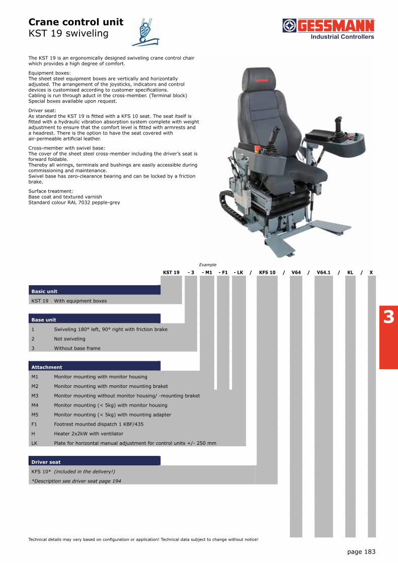
Crane control unit KST 19 swiveling
Technical details may vary based on configuration or application! Technical data subject to change without notice!
The KST 19 is an ergonomically designed swiveling crane control chair which provides a high degree of comfort.
Equipment boxes: The sheet steel equipment boxes are vertically and horizontally adjusted. The arrangement of the joysticks, indicators and control devices is customised according to customer specifications. Cabling is run through aduct in the cross-member. (Terminal block) Special boxes available upon request.
Driver seat: As standard the KST 19 is fitted with a KFS 10 seat. The seat itself is fitted with a hydraulic vibration absorption system complete with weight adjustment to ensure that the comfort level is fitted with armrests and a headrest. There is the option to have the seat covered with air-permeable artificial leather.
Cross-member with swivel base: The cover of the sheet steel cross-member including the driver’s seat is forward foldable. Thereby all wirings, terminals and bushings are easily accessible during commissioning and maintenance. Swivel base has zero-clearance bearing and can be locked by a friction brake.
Surface treatment: Base coat and textured varnish Standard colour RAL 7032 pepple-grey
KST 19 - 3 - M1 - F1 - LK / KFS 10 / V64 / V64.1 / KL / X
Basic unit
KST 19 With equipment boxes
Base unit
1 Swiveling 180° left, 90° right with friction brake
2 Not swiveling
3 Without base frame
Attachment
M1 Monitor mounting with monitor housing
M2 Monitor mounting with monitor mounting braket
M3 Monitor mounting without monitor housing/ -mounting braket
M4 Monitor mounting (< 5kg) with monitor housing
M5 Monitor mounting (< 5kg) with mounting adapter
F1 Footrest mounted dispatch 1 KBF/435
H Heater 2x2kW with ventilator
LK Plate for horizontal manual adjustment for control units +/- 250 mm
Driver seat
KFS 10* (included in the delivery!)
*Description see driver seat page 194
Example

page 184
V20
15/1
10.
02.2
015
3
Crane control unit KST 19 swiveling
Technical details may vary based on configuration or application! Technical data subject to change without notice!
KST15 - 3 - M1 - F1 - LK / KFS10 / V64 / V64.1 / KL / X
Mounting for equipment boxes
V... Multi-axis controller (see page 1)
S... Single-axis controller (see page 65)
D... Double-handle controller (see page 45)
N... Control-switch (see page 101)
... More command and indicating devices (see page 162)
Wiring
KL Without wiring, but terminal block built in each terminal
KLV On terminal block 4 qmm with single wire 1 qmm each terminal
KLV On SPS (SPS provision) with single wire 1 qmm each terminal
KLVA External wiring single wire highly flexible 1,5 qmm 5 m long each terminal
Special model
X Special / customer-specific
X� Special painted

page 185
3
Crane control unit KST 19 swiveling
Technical details may vary based on configuration or application! Technical data subject to change without notice!
539
±20
*
Equipment boxin centre
adjustable±22
Equipment boxin centre
adjustable±22
KFS 10
Ver
tical
wei
ght
adju
stm
ent
seat
incl
. eq
uipm
ent
boxe
s(w
eigh
t lo
aded
)
Monitor mountingsupport rotableabout monitor <5kgleft or right
Monitor mountingsupport rotableabout monitor >5kgleft or right
205
-50
*
170
284 ±80 *
658 +338-288 *
7,5° 90° stepless
Horizontaladjustment seat
200 40
Horizontal adjustmentseat with equipment boxes
125 125
Horizontal adjustmentof equipment boxes
90 176
Ver
tical
adj
ustm
ent
equi
pmen
t bo
xes
to s
eat
12°
12°
Inclinationadjustementof equipmentboxes
Backrestadjustable
max. 1050
45° 45°
90° 180°
min.590max.1100 Direction of view
left box45° to the middlerotable
right box45° to the middlerotable
±17
0se
atcu
shio
nde
pth
adju
stm
ent
monitor mountingsupport rotable
monitor mountingsupport rotable
24
0
30
0
14 Floor mounting
cable inlet Ø100
2/1112014
* adjustable

page 186
V20
15/1
10.
02.2
015
3
Driver seatKFS 2
Technical details may vary based on configuration or application! Technical data subject to change without notice!
The crane driver`s seat KFS 2 has stepless high adjustment by means of a gas-loaded spring. The backrest can be tilted, forwards onto the cushion, which in turn can then be tilted 90° sideways. All these functions are performed easily via levers.
Technical data:
Horizontal adjustment 100 mm
Inclination of the backrest max. 10°
Height adjustment 120 mm
KFS 22
Driver seat
KFS 21 with air-permeable artificial leather cover black
KFS 22 with textil cover grey / black
Example

page 187
3
Driver seatKFS 2
Technical details may vary based on configuration or application! Technical data subject to change without notice!
54
200 275
120 400...470
160...260
420
...5
40
750
...9
60
320
...3
90
120
160
14
Floor mounting
2/1302014

page 188
V20
15/1
10.
02.2
015
3
Driver seatKFS 4
Technical details may vary based on configuration or application! Technical data subject to change without notice!
The crane driver`s seat KFS 4 has stepless high adjustment by means of a gas-loaded spring and an oilhydraulic vibration absorption system with weight adjustment. The backrest can be tilted, forwards into the cushion, which in turn can then be tilted 90° sideways. All functions are performed by a simple lever operation. The metal parts are protected against corrosion and painted black.
Technical data:
Suspension stoke 80 mm
Weight adjustment 50 - 130 kg
Horizontal adjustment 100 mm
Inclination of the backrest max. 20°
Height adjustment 100 mm
KFS 42 - A1
Driver seat
KFS 41 Driver seat with air-permeable artificial leather cover black
KFS 42 Driver seat with textil cover grey / black
Attachment
A1 Armrest fully adjustable (2 pieces) 50 mm wide
A2 Armrest fully adjustable (2 pieces) 100 mm wide
Example

page 189
3
Driver seatKFS 4
Technical details may vary based on configuration or application! Technical data subject to change without notice!
420
500 ... 630
20°
890
...
990
130 ... 280
314
410
4
80 .
.. 5
80
335 255
450
150
290
210
8,
5
Floor mounting

page 190
V20
15/1
10.
02.2
015
3
Driver seatKFS 8
Technical details may vary based on configuration or application! Technical data subject to change without notice!
The crane driver`s seat KFS 8 is a static seat with ergonomically designed and provides a high grade of comfort. The driver`s seat is equipped with roller-bearing swivel system. All adjustment controls are positioned ergonomically within easy access. The metal parts are protected against corrosion and painted black.
Technical data:
Horizontal adjustment 150 mm
Inclination of the backrest max. 28°
Height adjustment 65 mm
KFS 82 - A1 - S1 - U
Driver seat
KFS 82 Driver seat with textil cover grey / black
Attachment
K Headrest
A1 Armrest fully adjustable (2 pieces) 50 mm wide
A2 Armrest fully adjustable (2 pieces) 100 mm wide
S1 Safety belt 2-point mounting
U Base frame (Apron)
Example

page 191
3
Driver seat KFS 8
Technical details may vary based on configuration or application! Technical data subject to change without notice!
216
325
9
510...760
28°
7x4°
480...610
450
75 75
horizontaladjustment
560
210
±30
*
742
±30
*
490
Seat swivelled90° (right)endpointsto lock
wei
ght
load
ed
Mounting dimensionsof the seat rails
2/1392014
* adjustable
page 192
V20
15/1
10.
02.2
015
3
Driver seat KFS 9
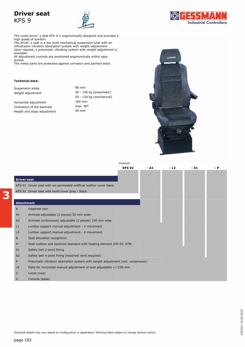
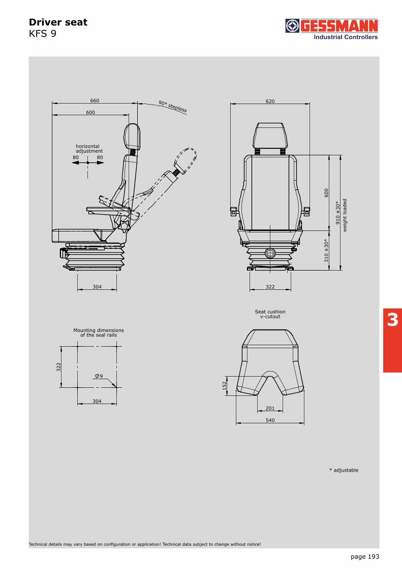
Technical details may vary based on configuration or application! Technical data subject to change without notice!
The crane driver`s seat KFS 9 is ergonomically designed and provides a high grade of comfort. The driver`s seat is a low level mechanical suspension seat with an oilhydraulic vibration absorption system with weight adjustment. Upon request, a pneumatic vibrating system with weight adjustment is available. All adjustment controls are positioned ergonomically within easy access. The metal parts are protected against corrosion and painted black.
Technical data:
Suspension stoke 80 mm
Weight adjustment 50 - 150 kg (pneumatic)50 - 130 kg (mechanical)
Horizontal adjustment 160 mm
Inclination of the backrest max. 90°
Height and slope adjustment 60 mm
KFS 92 - A1 - L2 - S1 - P
Driver seat
KFS 91 Driver seat with air-permeable artificial leather cover black
KFS 92 Driver seat with textil cover grey / black
Attachment
K Headrest rain
A1 Armrest adjustable (2 pieces) 50 mm wide
A2 Armrest continuously adjustable (2 pieces) 100 mm wide
L1 Lumbar support manual adjustment - 2 movement
L2 Lumbar support manual adjustment - 4 movement
B Seat allocation recognition
H Seat cushion and backrest standard with heating element 24V DC 47W
S1 Safety belt 2 point fixing
S2 Safety belt 4 point fixing (headrest raint required)
P Pneumatic vibration absorption system with weight adjustment (incl. compressor)
LK Plate for horizontal manual adjustment of seat adjustable +/-250 mm
C Loose cover
U Console (base)
Example
page 193
3
Driver seat KFS 9
Technical details may vary based on configuration or application! Technical data subject to change without notice!
322
304
9
660
304
600
90° stepless
80 80
horizontaladjustment
310
±30
* 6
00
620
322
910
±30
* w
eigh
t lo
aded
201
540
152
Seat cushionv-cutout
Mounting dimensionsof the seal rails
2/1412014
* adjustable

page 194
V20
15/1
10.
02.2
015
3
Driver seat KFS 10
Technical details may vary based on configuration or application! Technical data subject to change without notice!
KFS 102 - A1 - L2 - S2 - R1
Driver seat
KFS 101 Driver seat with air-permeable artificial leather cover black
KFS 102 Driver seat with textil cover grey / black
Attachment
K Headrest raint
A1 Armrest adjustable (2 pieces) 50 mm wide
A2 Armrest continuously adjustable (2 pieces) 100 mm wide
L1 Lumbar support manual adjustment - 2 movement
L2 Lumbar support manual adjustment - 4 movement
B Seat allocation recognition
H Seat cushion and backrest with heating element 24VDC 47W
S1 Safety belt 2 point fixing
S2 Safety belt 4 point fixing (headrest raint required)
U Console (base)
R1 Price reduction pneumatic vibration absorption system
R2 Price reduction for seat cushion without V-cut
The crane driver`s seat KFS 10 is ergonomically designed and provides a high grade of comfort. The driver`s seat has a pneumatic vibration absorption system with weight adjustment by compressor (24 V DC 8 Ampere) and a standard seat cushion V-cut. Through its three horizontal adjustment, it can be flexibly adapted to very many applications. All adjustment controls are positioned ergonomically within easy access. The metal parts are protected against corrosion and painted black.
Technical data:
Suspension stoke 80 mm
Weight adjustment 50 - 150 kg (pneumatic)50 - 130 kg (mechanical)
Horizontal adjustmentSeat with suspension system 160 mm
Seat part individuell 240 mm
Seat cushion 160 mm
Inclination of the backrest max. 90°
Height and slope adjustment 60 mm
Example

page 195
3
Driver seat KFS 10
Technical details may vary based on configuration or application! Technical data subject to change without notice!
322
304
9
370
±20
* 6
00
970
±20
*
530
620
Pneumatic suspension systemby compressor
wei
ght
load
ed
480...610
510 -160 90° stepless
60
Vertical adjustmentmechanical/manual
80 80
40 200
Horizontaladjustment seatwith suspension system
Horizontaladjustment seatwith backrest
160
Horizontal adjustmentonly seat cushion
201
540
152
Seat cushionV-cutout
* adjustable
2/1432014
Mounting dimensions seat

page 196
V20
15/1
10.
02.2
015
3
Driver seatKFS 11
Technical details may vary based on configuration or application! Technical data subject to change without notice!
The crane driver`s seat KFS 11 is ergonomically designed and provides a high grade of comfort. The driver`s seat is a low level mechanical suspension seat with an oilhydraulic vibration absorption system with weight adjustment. All adjustment controls are positioned ergonomically within easy access. The metal parts are protected against corrosion and painted black.
Technical data:
Suspension stoke 80 mm
Weight adjustment 50 - 150 kg
Horizontal adjustment 230 mm
Inclination of the backrest -12°/+40°
Slope adjustment -10°/+12°
Height adjustment 65 mm
KFS 11 - A1 - S1
Driver seat
KFS 11 Driver seat with textil cover grey / black
Attachment
K Headrest raint
A1 Armrest adjustable (2 pieces) 50 mm wide
A2 Armrest continuously adjustable (2 pieces) 100 mm wide
H Seat cushion and backrest with heating element 24VDC 47W
S1 Safety belt 2 point fixing
LK Plate for horizontal manual adjustment of seat adjustable +/-250 mm
C Loose cover
U Console (base)
Example

page 197
3
Driver seatKFS 11
Technical details may vary based on configuration or application! Technical data subject to change without notice!
225
390
10,50
560 .... 970 30°
Horizontaladjustment
100 100
Mounting base dimensions
Mounting dimensionsof the seat rails
490
590
220
2
90 ±
30 *
6
30
114
0 ±
30 *
225
265
9
216 3
58
10
20
Special equipment
Floor mounting plate
730
114
0 ±
30 *
Armrest 100mm wide
555 95
20
215
3 x 330 = 690
720
2 x
215
= 4
30
460
Countersink DIN74-A4
Driver seat KFS 11
* adjustable

page 198
V20
15/1
10.
02.2
015
3
Driver seat KFS 12
Technical details may vary based on configuration or application! Technical data subject to change without notice!
The crane driver`s seat KFS 12 is ergonomically designed and provides a high grade of comfort. The driver's seat is equipped with an air-sprung vibration system. The weight adjustment is infinitely. Heated seats 24V, lumbar support, seat cushion adjustment, seat allocation recognition and headrest raint are included in the standard delivery. All adjustment controls are positioned ergonomically within easy access. The metal parts are protected against corrosion and painted black.
Technical data:
Suspension stoke 80 mm
Weight adjustment 50 - 150 kg
Horizontal adjustment 230 mm
Inclination of the backrest -12°/+40°
Slope adjustment -10°/+12°
Height adjustment 100 mm
Seat cushion adjustment 60 mm
KFS 12 - A1 - S1
Driver seat
KFS 12 Driver seat with textil cover grey / black
Attachment
A1 Armrest adjustable (2 pieces) 50 mm wide
A2 Armrest continuously adjustable (2 pieces) 100 mm wide
S1 Safety belt 2 point fixing
LK Plate for horizontal manual adjustment of seat adjustable +/-250 mm
C Loose cover
U Console (base)
Example

page 199
3
Driver seatKFS 12
Technical details may vary based on configuration or application! Technical data subject to change without notice!
lumbar support
225
390
10,50
560 .... 970 40°
Horizontaladjustment
100 100
Mounting basedimensions
Mounting dimensionsof the seat rails
490
590
220
2
90 ±
30 *
6
30
114
0 ±
30 *
225
265
9
216 3
58
10
20
Special equipment
Floor mounting plate
730
114
0 ±
30 *
Armrest 100mm wide
555 95
20
215
3 x 330 = 690
720
2 x
215
= 4
30
460
Countersink DIN74-A4
Driver seat KFS 12
* adjustable

page 200
V20
15/1
10.
02.2
015
3
Portable control unit TS 1
Cable and wiring
Cable Oelflex 18x1 mm 13,4 mm Ø -5°C til +80°C each metre
Cable Oelflex 25x1 mm 15,4 mm Ø -5°C til +80°C each metre
Cable Oelflex 34x1 mm 18,6 mm Ø -5°C til +80°C each metre
Cable Neonflex 18x1 mm 19,2 mm Ø -30°C til +80°C each metre
Cabel Neonflex 24x1 mm 22,1 mm Ø -30°C til +80°C each metre
Cabel Neonflex 38x1 mm 26,1 mm Ø -30°C til +80°C each metre
KLS Wired on connector / plug in socket per core
KLK Wiring for cable per core Technical details may vary based on configuration or application! Technical data subject to change without notice!
The portable control unit TS 1 is used for controlling and monitoring the necessary equipment. The chest panel and straps enable the operator to carry it without becoming tired. An adjustable carrying strap can also be fitted for use without the chest plate.
Surface treatment: Priming and structur-finishing paint Standard colour RAL 7032 pepple-grey
Technical data:
Operation temperature -40°C to +60°C
Degree of protection IP 54
TS 1 - SB 1 - RH 1 - K 4 - HS 1 / V... / KLS / X
Basic unit
TS 1 with chest plate and straps
TS 11 with straps
Attachment
SB 1 Legs for control unit alu-tube 2 pieces
SB 2 Legs for control unit stainless steel-tube V2 A 2 pieces
RH 1 Reeling hooks for control unit stainless steel V2 A
K 1 Cable entry M 32 cable 11-21 mm
K 2 Cable entry M 40 cable 19-28 mm
K 3 Cable entry 180° swiveling M 32 cable 11-21 mm
K 4 Cable entry 180° swiveling M 40 cable 19-28 mm
HS 1 Plug in socket 16-pole male insert HAN 16 E without wiring
HB 1 Connector 16-pole female insert HAN 16 E without wiring
HS 2 Plug in socket 24-pole female insert HAN 24 E without wiring
HB 2 Connector 24-pole female insert HAN 24 E without wiring
HS 3 Plug in socket 32-pole male insert HAN 32 E without wiring
HB 3 Connector 32-pole female insert HAN 32 E without wiring
Indicating labels not engraved for multi-axis-/ single-axis controller
Indicating labels engraved for multi-axis-/ single-axis controller
Mountig for equipment boxes
V Multi-axis controller (see page 1)
S Single-axis controller (see page 65)
N Control-switch (see page 101)
... More command and indicating devices (see page 162)
Example

page 201
3
Portable control unit TS 1
TS 1 - SB 1 - RH 1 - K 4 - HS 1 / V... / KLS / X
Special model
X Special / customer-specific
X1 Housing antistatic design < 109 Ohm/cm
X2 Finishing colour yellow RAL 1021
Technical details may vary based on configuration or application! Technical data subject to change without notice!

page 202
V20
15/1
10.
02.2
015
3
V20
13/1
20.
08.2
013
Portable control unit TS 1
Technical details may vary based on configuration or application! Technical data subject to change without notice!
106
1
20
With chest plate and strapsProtection IP 65with multi-axis controllers IP 54
Cable entry with anti-kink protectionand stain relief or connectors
250
442
305
265
Direction of view
2
3 4
1 5
6
87
With adjustable carrying strapProtection IP 65 with multi-axis controllers IP 54

page 203
3
Portable control unit TS 2
Technical details may vary based on configuration or application! Technical data subject to change without notice!
The portable control unit TS 2 is used for controlling and monitoring the necessary equipment. The chest panel and straps enable the operator to carry it without becoming tired. An adjustable carrying strap can also be fitted for use without the chest plate.
Surface treatment: Priming and structur-finishing paint Standard colour RAL 7032 pepple-grey
Technical data:
Operation temperature -40°C to +60°C
Degree of protection IP 65
TS 2 - SB 1 - RH 1 - K 4 - HS 1 / V... / KLS / X
Basic unit
TS 2 with chest plate, straps
TS 21 with straps
TS 22 with bracket and straps
Attachment
SB 1 Legs for control unit alu-tube 2 pieces
SB 2 Legs for control unit stainless steel-tube V2 A 2 pieces
RH 1 Reeling hooks for control unit stainless steel V2 A
K 1 Cable entry M 32 cable 11-21 mm
K 2 Cable entry M 40 cable 19-28 mm
K 3 Cable entry 180° swiveling M 32 cable 11-21 mm
K 4 Cable entry 180° swiveling M 40 cable 19-28 mm
HS 1 Plug in socket 16-pole male insert HAN 16 E without wiring
HB 1 Connector 16-pole female insert HAN 16 E without wiring
HS 2 Plug in socket 24-pole female insert HAN 24 E without wiring
HB 2 Connector 24-pole female insert HAN 24 E without wiring
HS 3 Plug in socket 32-pole male insert HAN 32 E without wiring
HB 3 Connector 32-pole female insert HAN 32 E without wiring
Indicating labels not engraved for multi-axis-/ single-axis controller
Indicating labels engraved for multi-axis-/ single-axis controller
Mountig for equipment boxes
V Multi-axis controller (see page 1)
S Single-axis controller (see page 65)
N Control-switch (see page 101)
... More command and indicating devices (see page 162)
Example

page 204
V20
15/1
10.
02.2
015
3
Portable control unit TS 2
Special model
X Special / customer-specific
X1 Housing antistatic design < 109 Ohm/cm
X2 Finishing color yellow RAL 1021
TS 2 - SB 1 - RH 1 - K 4 - HS 1 / V... / KLS / X
Cable and wiring
Cable Oelflex 18x1 mm 13,4 mm Ø -5°C til +80°C each metre
Cable Oelflex 25x1 mm 15,4 mm Ø -5°C til +80°C each metre
Cable Oelflex 34x1 mm 18,6 mm Ø -5°C til +80°C each metre
Cable Neonflex 18x1 mm 19,2 mm Ø -30°C til +80°C each metre
Cable Neonflex 24x1 mm 22,1 mm Ø -30°C til +80°C each metre
Cable Neonflex 38x1 mm 26,1 mm Ø -30°C til +80°C each metre
KLS Wired on connector / plug in socket per core
KLK Wiring for cable per core
Technical details may vary based on configuration or application! Technical data subject to change without notice!

page 205
3
Portable control unit TS 2
Technical details may vary based on configuration or application! Technical data subject to change without notice!
140
1
14
With chest plate and strapsProtection IP 65with multi-axis controllers IP 54
Cable entrywith anti-kink protectionand stain relief or connectors
250
2
20
335
Direction of view
With adjustable carrying strapProtection IP 65 with multi-axis controllers IP 54
120
With bracket and cable entry swivellingProtection IP 65with multi-axis controllers IP 54
Cable entry 180° swivellingwith anti-kink protectionand stain relief or connectors
464
page 206
V20
15/1
10.
02.2
015
3
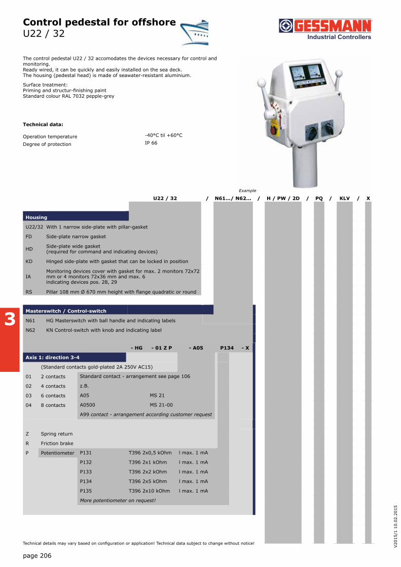
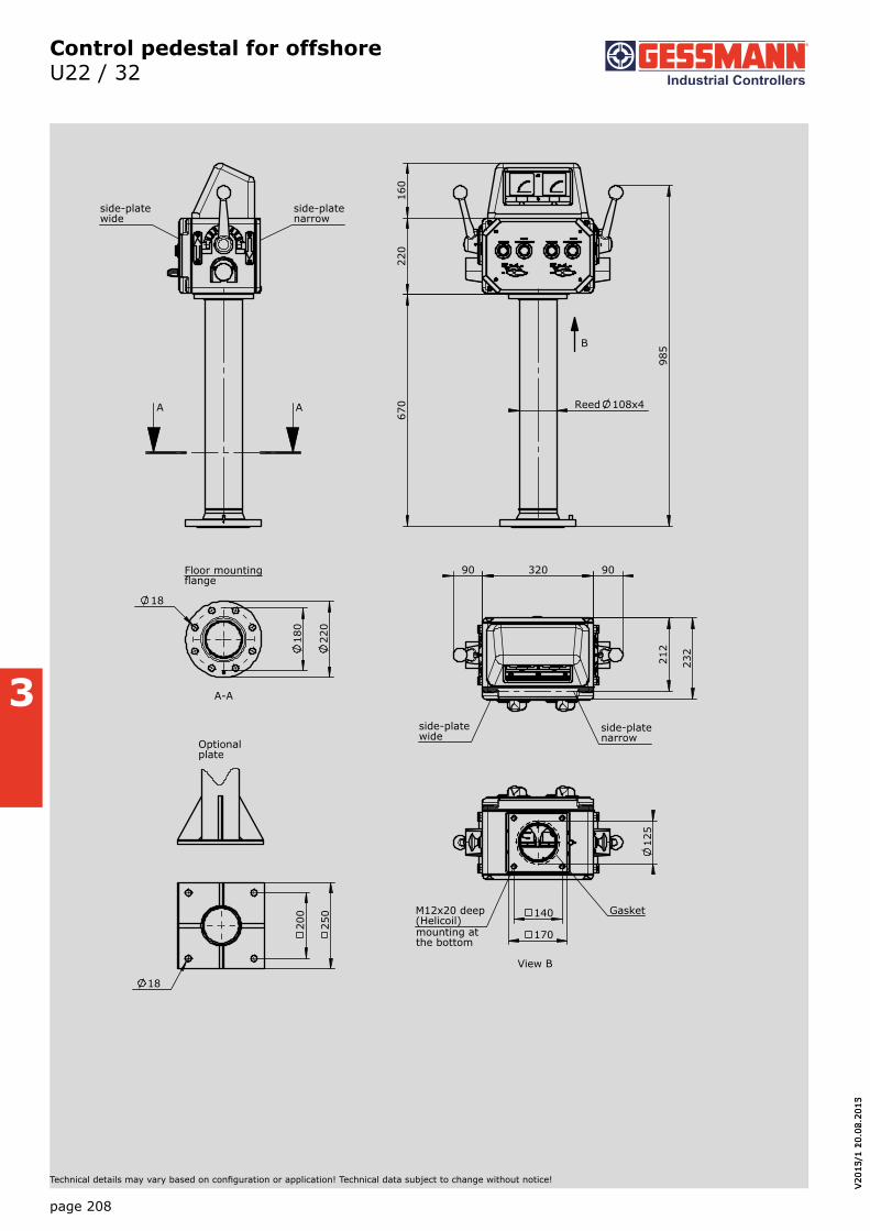
Control pedestal for offshoreU22 / 32
Technical details may vary based on configuration or application! Technical data subject to change without notice!
The control pedestal U22 / 32 accomodates the devices necessary for control and monitoring. Ready wired, it can be quickly and easily installed on the sea deck. The housing (pedestal head) is made of seawater-resistant aluminium.
Surface treatment: Priming and structur-finishing paint Standard colour RAL 7032 pepple-grey
Technical data:
Operation temperature -40°C til +60°C
Degree of protection IP 66
U22 / 32 / N61.../ N62... / H / PW / 2D / PQ / KLV / X
Housing
U22/32 With 1 narrow side-plate with pillar-gasket
FD Side-plate narrow gasket
HD Side-plate wide gasket (required for command and indicating devices)
KD Hinged side-plate with gasket that can be locked in position
IAMonitoring devices cover with gasket for max. 2 monitors 72x72 mm or 4 monitors 72x36 mm and max. 6 indicating devices pos. 28, 29
RS Pillar 108 mm Ø 670 mm height with flange quadratic or round
Masterswitch / Control-switch
N61 HG Masterswitch with ball handle and indicating labels
N62 KN Control-switch with knob and indicating label
Example
- HG - 01 Z P - A05 P134 - X
Axis 1: direction 3-4
(Standard contacts gold-plated 2A 250V AC15)
01 2 contacts Standard contact - arrangement see page 106
02 4 contacts z.B.
03 6 contacts A05 MS 21
04 8 contacts A0500 MS 21-00
A99 contact - arrangement according customer request
Z Spring return
R Friction brake
P Potentiometer P131 T396 2x0,5 kOhm l max. 1 mA
P132 T396 2x1 kOhm l max. 1 mA
P133 T396 2x2 kOhm l max. 1 mA
P134 T396 2x5 kOhm l max. 1 mA
P135 T396 2x10 kOhm l max. 1 mA
More potentiometer on request!

page 207
3
Control pedestal for offshoreU22 / 32
Technical details may vary based on configuration or application! Technical data subject to change without notice!
U22 / 32 / N61.../N62... / H / PW / 2D / PQ / KLV / X
Command and indicating devices
H Heating 20 Watt 220 or 110 V 50/60 Hz
PV Mushroom head push button latching 22 latching with indicating label 1 Ö
P Mushroom head push button 22 with indicating label 1 S
D Push button 22 with indicating label 1 S
W Selector switch 0--1 22 with indicating label 1 S
L Indicator light 22 with indicating label Diode 24 Volt
L Indicator light 22 with indicating label Diode 230 Volt AC
Contact block additional 1 S or 1 Ö
L Indicator light 22 with indicating label Diode 24 Volt protection IP65
L Indicator light 10 with indicating label Diode 24 Volt protection IP65
Display devices
PQ Powermeter PQ 72 1mA DC Engraved your instructions
PQI Powermeter PQ 72 1mA DC illuminated 24 Volt Engraved your instructions
PQ Powermeter PQ 72x36 1 mA DC Engraved your instructions
PQI Powermeter PQ 72x36 1 mA DC illuminated 24 Volt Engraved your instructions
EQ Amperemeter EQ 72 100/200/ 1A Engraved your instructions
EQI Amperemeter EQ 72 100/200/ 1A illuminated 24 Volt Engraved your instructions
EQ Amperemeter EQ 72x36 100/200/1A Engraved your instructions
EQI Amperemeter EQ 72x36 100/200/1A illuminated 24 Volt Engraved your instructions
Wiring
KLV on terminal block 2,5 qmm with wire line 0,75 qmm
Special model
X Special / customer-specific
page 208
V20
15/1
10.
02.2
015
3
V20
13/1
20.
08.2
013
Control pedestal for offshoreU22 / 32
Technical details may vary based on configuration or application! Technical data subject to change without notice!
670
2
20
160
985
Reed 108x4
B
AA
side-platenarrow
side-platewide
320 90 90
232
212
side-platenarrow
side-platewide
170
140
12
5
GasketM12x20 deep(Helicoil)
View B
22
0
18
0
18
A-A
Floor mountingflange
20
0
25
0
18
Optional plate
2/1612014
mounting atthe bottom

page 209
3
Control pedestal for offshoreU23 / 23
Technical details may vary based on configuration or application! Technical data subject to change without notice!
The control pedestal U22 / 23 accomodates the devices necessary for control and monitoring. Ready wired, it can be quickly and easily installed on the sea deck. The housing (pedalstel head) is made of seawater-resistant aluminium.
Surface treatment: Priming and structur-finishing paint Standard colour RAL 7032 pepple-grey
Technical data:
Operation temperature -40°C to +60°C
Degree of protection IP 66
Example
U23 / 23 / N61.../N62... / H / PW / 2D / PQ / KLV / X
Housing
U23/23 with 1 narrow side-plate with pillar-gasket
U23/23A Side-plate narrow gasket
IAMonitoring devices cover with gasket for max. 2 monitors 72x72 mm or 4 monitors 72x36 mm and max. 6 indicating devices pos. 28, 29
RS Pillar 108 mm Ø 670 mm height with flange quadratic or round
Masterswitch / Control-switch
N61 HG Masterswitch with ball handle and indicating labels
N62 KN Control-switch with knob and indicating label
- HG - 01 Z P - A05 P134 - X
Axis 1: direction 3-4
(Standard contacts gold-plated 2A 250V AC15)
01 2 contacts Standard contact - arrangement see page 106
02 4 contacts z.B.
03 6 contacts A05 MS 21
04 8 contacts A0500 MS 21-00
A99 contact - arrangement according customer request
Z Spring return
R Friction brake
P Potentiometer P131 T396 2x0,5 kOhm l max. 1 mA
P132 T396 2x1 kOhm l max. 1 mA
P133 T396 2x2 kOhm l max. 1 mA
P134 T396 2x5 kOhm l max. 1 mA
P135 T396 2x10 kOhm l max. 1 mA
More potentiometer on request!

page 210
V20
15/1
10.
02.2
015
3
Control pedestal for offshoreU23 / 23
Technical details may vary based on configuration or application! Technical data subject to change without notice!
U23 / 23 / N61.../N62... / H / PW / 2D / PQ / KLV / X
Command and indicating devices
H Heating 20 Watt 220 or 110 V 50/60 Hz
PV Mushroom head push button latching 22 latching with indicating label 1 Ö
P Mushroom head push button 22 with indicating label 1 S
D Push button 22 with indicating label 1 S
W Selector switch 0--1 22 with indicating label 1 S
L Indicator light 22 with indicating label Diode 24 Volt
L Indicator light 22 with indicating label Diode 230 Volt AC
Contact block additional 1 S or 1 Ö
L Indicator light 22 with indicating label Diode 24 Volt protection IP65
L Indicator light 10 with indicating label Diode 24 Volt protection IP65
Display devices
PQ Powermeter PQ 72 1mA DC Engraved your instructions
PQI Powermeter PQ 72 1mA DC illuminated 24 Volt Engraved your instructions
PQ Powermeter PQ 72x36 1 mA DC Engraved your instructions
PQI Powermeter PQ 72x36 1 mA DC illuminated 24 Volt Engraved your instructions
EQ Amperemeter EQ 72 100/200/ 1A Engraved your instructions
EQI Amperemeter EQ 72 100/200/ 1A illuminated 24 Volt Engraved your instructions
EQ Amperemeter EQ 72x36 100/200/1A Engraved your instructions
EQI Amperemeter EQ 72x36 100/200/1A illuminated 24 Volt Engraved your instructions
Wiring
KLV on terminal block 2,5 qmm with wire line 0,75 qmm
Special model
X Special / customer-specific

page 211
3
Control pedestal for offshoreU23 / 23
Technical details may vary based on configuration or application! Technical data subject to change without notice!
Reed 108x4
670
1
15
135
902
B
AA
140
200
23
0
12
5 li
M12x20 deep(Helicoil)
View B
Gasket
Mounting atthe bottom
Ø9Mounting at the top
18
18
0
22
0
A-A
Floor mountingflange
20
0
25
0
18
12
Optionalplate
170
135
Protection withnarrow cover
2/1632014

4
Naval cruise controller AZ1
Example
page 212
V20
15/1
10.
02.2
015
Technical details may vary based on configuration or application! Technical data subject to change without notice!
The naval cruise controller AZ1 is a rugged switching device. The modular design enables the switching device to be used universally. The design includes: The mechanical control-system for the engine speed 0-max. rpm. switching angle 60 degrees with pressure print at 7 degrees and friction brake direction 0-2. The mechanical control-system for the steering left/right direction 13-14, 360 degrees with pressure points 4x90 degrees and friction brake. The AZ1 is resistant to oil, maritime climate, ozone and UV radiation.
Technical data
Mechanical life AZ 1 12 million operating cycles
Operation temperature -40°C til +60°C
Degree of protection IP 66
AZ1 - L - N E2112 - X
Basic unit
AZ1 Naval cruise controller
Options
L Scale illuminated (LED) 24V dimmable
N Follow-up control system 24 Volt DC for direction 0-2 and 13-14
Interface
Voltage output (not stabilized)
Supply voltage 4,75-5,25VDC
Characteristic: 1 = contra rotating, 2 = concurrently rotating
0,5...2,5...4,5V redundant per axis 1 axis E103 1
2 axis 2
Voltage output
Supply voltage 9-32VDC (*11,5-32VDC)
Characteristic: 1 = contra rotating, 2 = concurrently rotating
0,5...2,5...4,5V redundant per axis 1 axis E111 1
2 axis 2
Output power
Supply voltage 9-32VDC
Characteristic: 1 = contra rotating, 2 = concurrently rotating
4...12...20mA redundant per axis 1 axis E211 1
2 axis 2
Special model
X Special / customer-specific

4
Naval cruise controller AZ1
145
137
+1
102,50
4,5
Hole pattern
289
,50
136
Edition:with motor rosseting control system
Plug-in socket/connector
155
136
197
141
50
68
66
41
60°
deten
t poin
t 7°
Installation depth withdistance washer
Installation depthwithout distance washer
Friction brakeengine speed
Friction break steering
13 14
Steering 360°, with detent 4 x 90°
Ausführung:Drucktaster Einbau Pos. 1,3,4,6,7,8Sensortaster ein oder beidseitig
3/051
page 213
Technical details may vary based on configuration or application! Technical data subject to change without notice!

4
Pedal-controller P7 / PP7
The pedal-controller P7 and PP7 is a rugged switching devices for footing applications. The pedal-controller is resistant to oil, maritime conditions e.g. offshore /vessels, UV radi-ation typically from the sun.
Technical data
mechanical life P7 6 million operating cycles
mechanical life PP7 10 million operating cycles
Operation temperature -40°C til +60°C
Degree of protection P7 IP 54
Degree of protection PP7 IP 65
Colour RAL 7032 pebble-grey
P7 - 1 Z P - A01 P124 -X
Basic unit
P7 Pedal-controller
reinforced version
PP7 Pedal-controller
Detent
without
R1 0-2
R2 0-3
R3 0-4
R4 1-0-1
R5 2-0-2
Direction 1-2
1 1 contact Standard contact - Arrangement see page 106
2 2 contacts z.B.
3 3 contacts MS 11 A01
4 4 contacts MS 12 A02
5 5 contacts MS 13 A03
6 6 contacts MS 14 A04
*only possible without potentiometer! MS 21 A05
A99 contact - arrangement according customer request
Z Spring return
R Friction brake
(P) Mounting options for potentiometer and encoder (Gessmann-types)
P Potentiometer P121 T374 0,5 kOhm l max. 1 mA
P122 T374 1 kOhm l max. 1 mA
P123 T374 2 kOhm l max. 1 mA
P124 T374 5 kOhm l max. 1 mA
P125 T374 10 kOhm l max. 1 mA
More potentiometer on demand!
Special model
X Special / customer-specific
Example
page 214
V20
15/1
10.
02.2
015
Technical details may vary based on configuration or application! Technical data subject to change without notice!

4
Pedal-controller P7 / PP7
195 47
90
250 175
25°
48
165
12,5° 12,5°
Cable entry M20
Mou
ntin
g ou
tsid
e 9
0
9(4 x M8)
Mou
ntin
g in
side
8
0
100
5,5(4 x M5x50)
115
50 7,5 12,5
3 /100
page 215
Technical details may vary based on configuration or application! Technical data subject to change without notice!


![W pn P S - PortfolioH7NMLC@NFDI ?I8> N? C7N>EI9>MNA K5B5432 6 B G < WVSQP 9L@Nz7 &$ $ e r $ ^ K e u ^_ a e2 ^] $6ev $ ^" 3 3 Y ^ vv6$ e 3f @ u3 " 3 3$ 3 ^ u3 vv6$ e 3 ^](https://img.pdfslide.net/doc/110x75/5f0c494e7e708231d434a60a/w-pn-p-s-portfolio-h7nmlcnfdi-i8-n-c7nei9mna-k5b5432-6-b-g-.jpg)