Embed Size (px)
Citation preview
Applications & Tools
Answers for industry.
Cover
Secure Remote Access to SIMATIC Stations with the SOFTNET Security Client via Internet and UMTS
Security with SCALANCE M875, SOFTNET Security Client
Application Description Jan 2013
2 RemoteAccess_SSC
V1.0, Entry ID: 24960449
Cop
yrig
ht
Sie
men
s A
G 2
012
All
right
s re
serv
ed
Siemens Industry Online Support This document is taken from Siemens Industry Online Support. The following link takes you directly to the download page of this document: http://support.automation.siemens.com/WW/view/en/24960449 Caution: The functions and solutions described in this entry are mainly limited to the realization of the automation task. In addition, please note that suitable security measures in compliance with the applicable Industrial Security standards must be taken, if your system is interconnected with other parts of the plant, the company’s network or the Internet. More information can be found under entry ID 50203404. http://support.automation.siemens.com/WW/view/en/50203404 For further information on this topic, you may also actively use our Technical Forum in the Siemens Industry Online Support. Share your questions, suggestions or problems and discuss them with our strong forum community: http://www.siemens.com/forum-applications
RemoteAccess_SSC V1.0, Entry D: 24960449 3
Cop
yrig
ht
Sie
men
s A
G 2
012
All
right
s re
serv
ed
s
SIMATIC Secure Remote Access Application Description
Task 1
Solution 2
Basic Information 3
Installation of the Application
4 Configuration of the Hardware
5
Operating the Application 6
Literature 7
History 8
Warranty and Liability
4 RemoteAccess_SSC
V1.0, Entry ID: 24960449
Cop
yrig
ht
Sie
men
s A
G 2
012
All
right
s re
serv
ed
Warranty and Liability
Note The application examples are not binding and do not claim to be complete regarding configuration, equipment and any eventuality. The application examples do not represent customer-specific solutions. They are only intended to provide support for typical applications. You are responsible for ensuring that the described products are used correctly. These application examples do not relieve you of your responsibility to use sound practices in application, installation, operation and maintenance. When using these application examples, you recognize that we will not be liable for any damage/claims beyond the liability clause described. We reserve the right to make changes to these application examples at any time and without prior notice. If there are any deviations between the recommendations provided in this application example and other Siemens publications – e.g. catalogs – the contents of the other documents have priority.
We do not accept any liability for the information contained in this document. Any claims against us – based on whatever legal reason – resulting from the use of the examples, information, programs, engineering and performance data etc., described in this Application Example shall be excluded. Such an exclusion shall not apply in the case of mandatory liability, e.g. under the German Product Liability Act (“Produkthaftungsgesetz”), in case of intent, gross negligence, or injury of life, body or health, guarantee for the quality of a product, fraudulent concealment of a deficiency or breach of a condition which goes to the root of the contract (“wesentliche Vertragspflichten”). The damages for a breach of a substantial contractual obligation are, however, limited to the foreseeable damage, typical for the type of contract, except in the event of intent or gross negligence or injury to life, body or health. The above provisions do not imply a change in the burden of proof to your disadvantage. It is not permissible to transfer or copy these application examples or excerpts thereof without express authorization from Siemens Industry Sector.
Table of Contents
RemoteAccess_SSC V1.0, Entry D: 24960449 5
Cop
yrig
ht
Sie
men
s A
G 2
012
All
right
s re
serv
ed
Table of Contents Warranty and Liability..............................................................................................4 Table of Contents.....................................................................................................5 1 Task.................................................................................................................6
1.1 Introduction .......................................................................................6 1.2 Overview of the automation task ........................................................6
2 Solution...........................................................................................................7 2.1 Overview of the general solution........................................................7 2.2 Detailed hardware setup ....................................................................8 2.3 Description of the core functions ......................................................10 2.3.1 Secure and reliable data communication..........................................10 2.3.2 Fixed access address despite dynamic IP address ..........................11 2.3.3 Introducing the displayed scenarios .................................................12 2.4 Hardware and software components used .......................................13
3 Basic Information .........................................................................................14 3.1 The VPN connection modes of the SCALANCE M875 .....................14 3.2 Establishing a connection via defined norms....................................15 3.2.1 The domain name system................................................................15 3.2.2 The dynamic domain name system service......................................17 3.3 Problems by using normal APNs......................................................17
4 Installation of the Application......................................................................18 5 Configuration of the Hardware.....................................................................20
5.1 Networking the components.............................................................20 5.2 Adapting the IP addresses...............................................................20 5.2.1 IP address of the service center.......................................................20 5.2.2 IP address of the components..........................................................21 5.3 Loading of the remote station...........................................................21 5.4 Commissioning of VPN tunnels........................................................23 5.4.1 Requirements..................................................................................23 5.4.2 Configuration with the Security Configuration Tool ...........................24 5.5 Configuration of the SCALANCE M875............................................30 5.6 Configuration of the SOFTNET Security Client.................................39 5.7 Final configuration ...........................................................................40
6 Operating the Application ............................................................................41 6.1 Scenario: Standard STEP 7 PG and online functions .......................41 6.2 Scenario: HTML-based access to the web-servers...........................44
7 Literature ......................................................................................................45 7.1 Bibliographic references ..................................................................45 7.2 Internet links....................................................................................45
8 History ..........................................................................................................46
1 Task 1.1 Introduction
6 RemoteAccess_SSC
V1.0, Entry ID: 24960449
Cop
yrig
ht
Sie
men
s A
G 2
012
All
right
s re
serv
ed
1 Task 1.1 Introduction
The increased Ethernet networking right up to field level offers significantly added value and advantages for automation systems especially for remote maintenance and diagnosis. However, this makes production processes that have so far been secure, vulnerable from outside and inside. Reliable security can only be provided by an approach that unites security mechanisms and a comprehensive understanding of automation.
1.2 Overview of the automation task
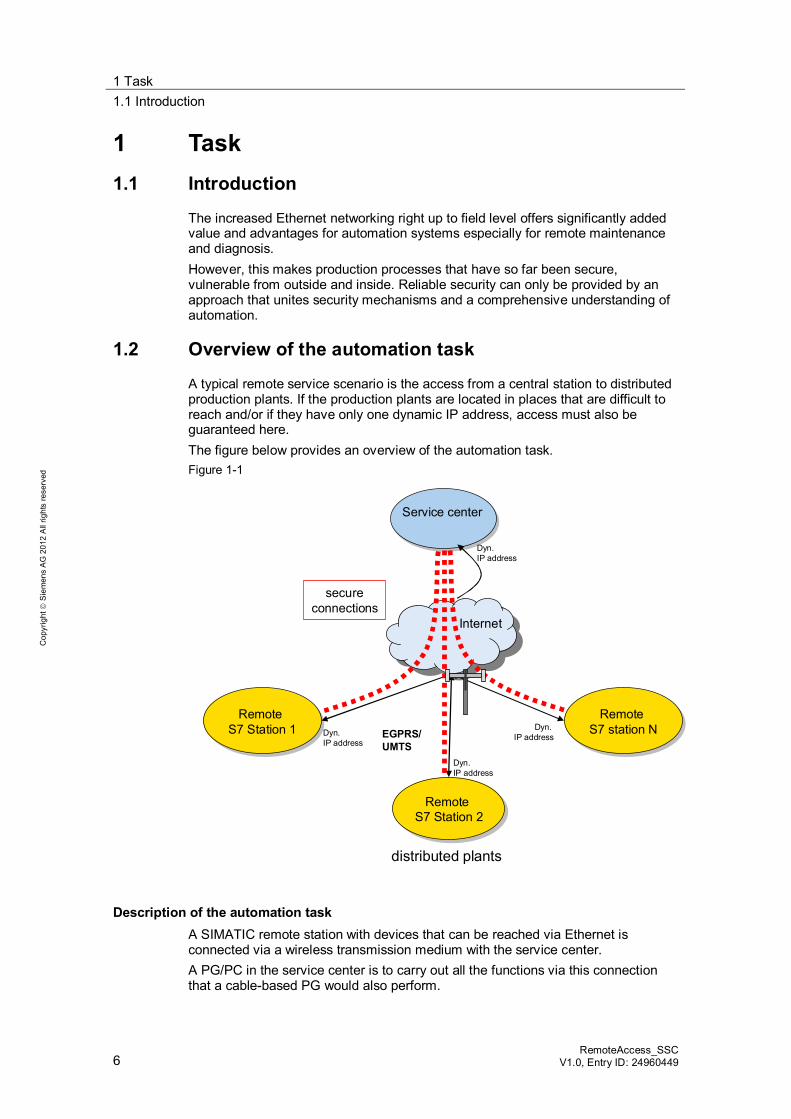
A typical remote service scenario is the access from a central station to distributed production plants. If the production plants are located in places that are difficult to reach and/or if they have only one dynamic IP address, access must also be guaranteed here. The figure below provides an overview of the automation task. Figure 1-1
Service centerService center
Remote S7 Station 1
Remote S7 Station 1
Remote S7 Station 2Remote
S7 Station 2
Remote S7 station N
Remote S7 station N
distributed plants
Internet
EGPRS/UMTS
secureconnections
Dyn. IP address
Dyn. IP address
Dyn. IP address
Dyn. IP address
Description of the automation task A SIMATIC remote station with devices that can be reached via Ethernet is connected via a wireless transmission medium with the service center. A PG/PC in the service center is to carry out all the functions via this connection that a cable-based PG would also perform.
2 Solution 2.1 Overview of the general solution
RemoteAccess_SSC V1.0, Entry D: 24960449 7
Cop
yrig
ht
Sie
men
s A
G 2
012
All
right
s re
serv
ed
2 Solution 2.1 Overview of the general solution
Schematic layout Siemens offers the following components with security functionality to secure accesses from and to production plants: Security modules SCALANCE S612 V3 and S623 The SOFTNET Security Client software CP1628 communication modules, CP 343-1 Advanced V3 and CP 443-1
Advanced V3 SCALANCE M875 UMTS router EDGE/GPRS router MD741-1
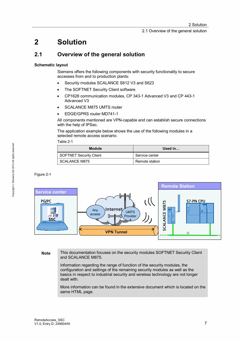
All components mentioned are VPN-capable and can establish secure connections with the help of IPSec. The application example below shows the use of the following modules in a selected remote access scenario. Table 2-1
Module Used in…
SOFTNET Security Client Service center SCALANCE M875 Remote station
Figure 2-1
Remote StationService center
PG/PC S7-PN CPU
IE
SCA
LAN
CE
M87
5
UMTSProvider
A
Internet
SSC
VPN Tunnel
Anyaccess
Note This documentation focuses on the security modules SOFTNET Security Client and SCALANCE M875.
Information regarding the range of function of the security modules, the configuration and settings of the remaining security modules as well as the basics in respect to industrial security and wireless technology are not longer dealt with.
More information can be found in the extensive document which is located on the same HTML page.
2 Solution 2.2 Detailed hardware setup
8 RemoteAccess_SSC
V1.0, Entry ID: 24960449
Cop
yrig
ht
Sie
men
s A
G 2
012
All
right
s re
serv
ed
Core contents of this application The following core points are discussed in this application: Integrating the SOFTNET Security Client and SCALANCE M875 in an example
concept: Establishing a secure connection between a central station and a remote station.
Step-by step explanation of the required configuration steps for implementing the example.
Presenting a solution for the use of dynamic IP addresses.
2.2 Detailed hardware setup
The following figures show the setup of this application in detail.
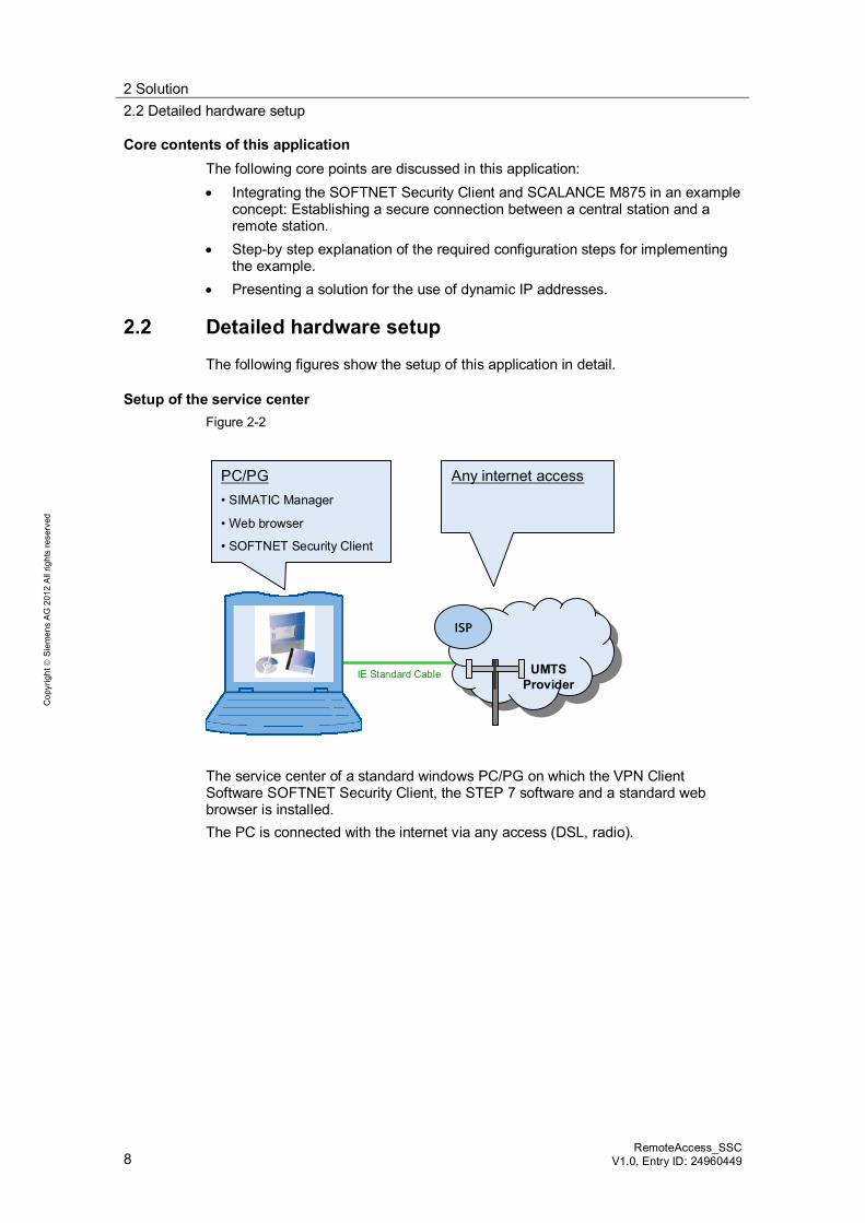
Setup of the service center Figure 2-2
Any internet accessPC/PG• SIMATIC Manager
• Web browser
• SOFTNET Security Client
IE Standard Cable
ISP
UMTSProvider
The service center of a standard windows PC/PG on which the VPN Client Software SOFTNET Security Client, the STEP 7 software and a standard web browser is installed. The PC is connected with the internet via any access (DSL, radio).
2 Solution 2.2 Detailed hardware setup
RemoteAccess_SSC V1.0, Entry D: 24960449 9
Cop
yrig
ht
Sie
men
s A
G 2
012
All
right
s re
serv
ed
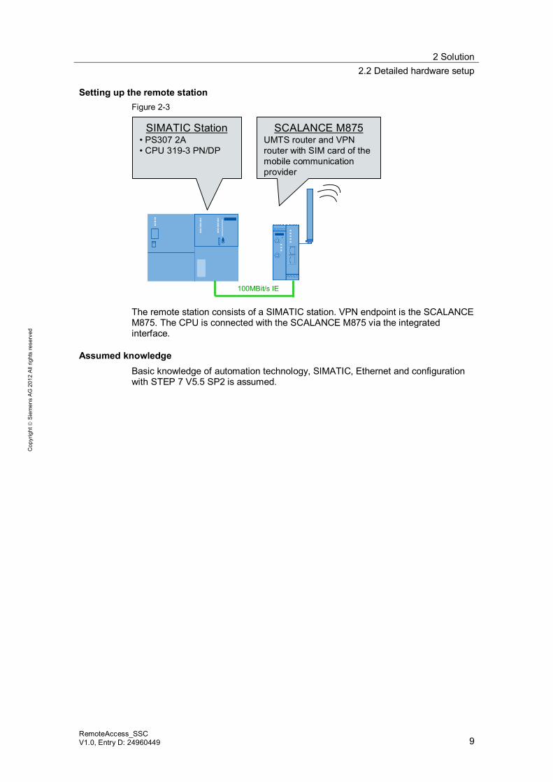
Setting up the remote station Figure 2-3
SCALANCE M875UMTS router and VPN router with SIM card of the mobile communicationprovider
100MBit/s IE
SIMATIC Station• PS307 2A• CPU 319-3 PN/DP
The remote station consists of a SIMATIC station. VPN endpoint is the SCALANCE M875. The CPU is connected with the SCALANCE M875 via the integrated interface.
Assumed knowledge Basic knowledge of automation technology, SIMATIC, Ethernet and configuration with STEP 7 V5.5 SP2 is assumed.
2 Solution 2.3 Description of the core functions
10 RemoteAccess_SSC
V1.0, Entry ID: 24960449
Cop
yrig
ht
Sie
men
s A
G 2
012
All
right
s re
serv
ed
2.3 Description of the core functions
In this application the focus is on two main core functions: Reliable and secure data exchange between a central control center and
remote stations. Accessibility of the stations despite dynamic IP address assignment by the
provider.
2.3.1 Secure and reliable data communication
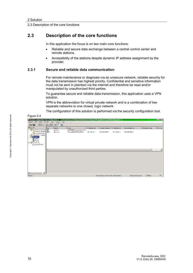
For remote maintenance or diagnosis via an unsecure network, reliable security for the data transmission has highest priority. Confidential and sensitive information must not be sent in plaintext via the internet and therefore be read and/or manipulated by unauthorized third parties. To guarantee secure and reliable data transmission, this application uses a VPN solution. VPN is the abbreviation for virtual private network and is a combination of two separate networks to one closed, logic network. The configuration of this solution is performed via the security configuration tool.
Figure 2-4
2 Solution 2.3 Description of the core functions
RemoteAccess_SSC V1.0, Entry D: 24960449 11
Cop
yrig
ht
Sie
men
s A
G 2
012
All
right
s re
serv
ed
2.3.2 Fixed access address despite dynamic IP address
Each network compatible device requires an IP address for the data exchange. As a matter of principle, two types are distinguished: Static IP addresses: The network device is assigned a unique and non-
changing IP address. Dynamic IP addresses: The network device receives a new and unknown IP
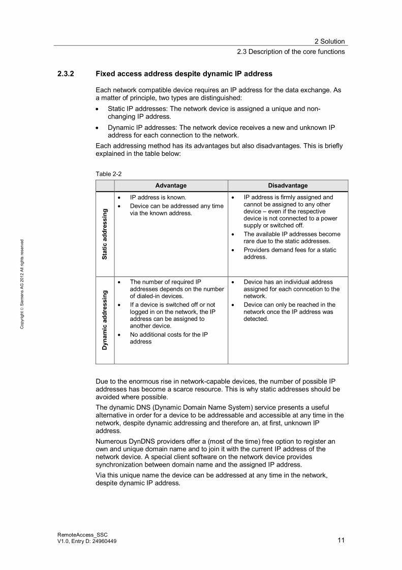
address for each connection to the network. Each addressing method has its advantages but also disadvantages. This is briefly explained in the table below: Table 2-2
Advantage Disadvantage
Stat
ic a
ddre
ssin
g
IP address is known. Device can be addressed any time
via the known address.
IP address is firmly assigned and cannot be assigned to any other device – even if the respective device is not connected to a power supply or switched off.
The available IP addresses become rare due to the static addresses.
Providers demand fees for a static address.
Dyn
amic
add
ress
ing
The number of required IP addresses depends on the number of dialed-in devices.
If a device is switched off or not logged in on the network, the IP address can be assigned to another device.
No additional costs for the IP address
Device has an individual address assigned for each conncetion to the network.
Device can only be reached in the network once the IP address was detected.
Due to the enormous rise in network-capable devices, the number of possible IP addresses has become a scarce resource. This is why static addresses should be avoided where possible. The dynamic DNS (Dynamic Domain Name System) service presents a useful alternative in order for a device to be addressable and accessible at any time in the network, despite dynamic addressing and therefore an, at first, unknown IP address. Numerous DynDNS providers offer a (most of the time) free option to register an own and unique domain name and to join it with the current IP address of the network device. A special client software on the network device provides synchronization between domain name and the assigned IP address. Via this unique name the device can be addressed at any time in the network, despite dynamic IP address.
2 Solution 2.3 Description of the core functions
12 RemoteAccess_SSC
V1.0, Entry ID: 24960449
Cop
yrig
ht
Sie
men
s A
G 2
012
All
right
s re
serv
ed
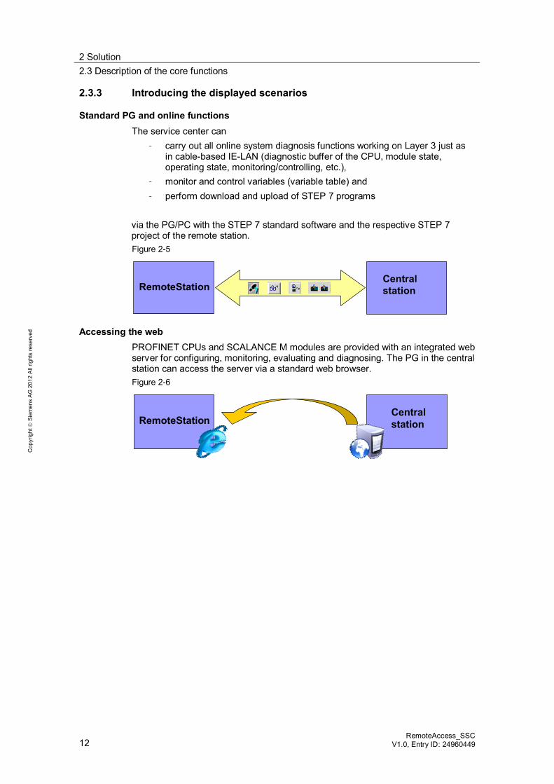
2.3.3 Introducing the displayed scenarios
Standard PG and online functions The service center can
– carry out all online system diagnosis functions working on Layer 3 just as in cable-based IE-LAN (diagnostic buffer of the CPU, module state, operating state, monitoring/controlling, etc.),
– monitor and control variables (variable table) and – perform download and upload of STEP 7 programs
via the PG/PC with the STEP 7 standard software and the respective STEP 7 project of the remote station. Figure 2-5
Central stationRemoteStation
Accessing the web PROFINET CPUs and SCALANCE M modules are provided with an integrated web server for configuring, monitoring, evaluating and diagnosing. The PG in the central station can access the server via a standard web browser. Figure 2-6
Central stationRemoteStation
2 Solution 2.4 Hardware and software components used
RemoteAccess_SSC V1.0, Entry D: 24960449 13
Cop
yrig
ht
Sie
men
s A
G 2
012
All
right
s re
serv
ed
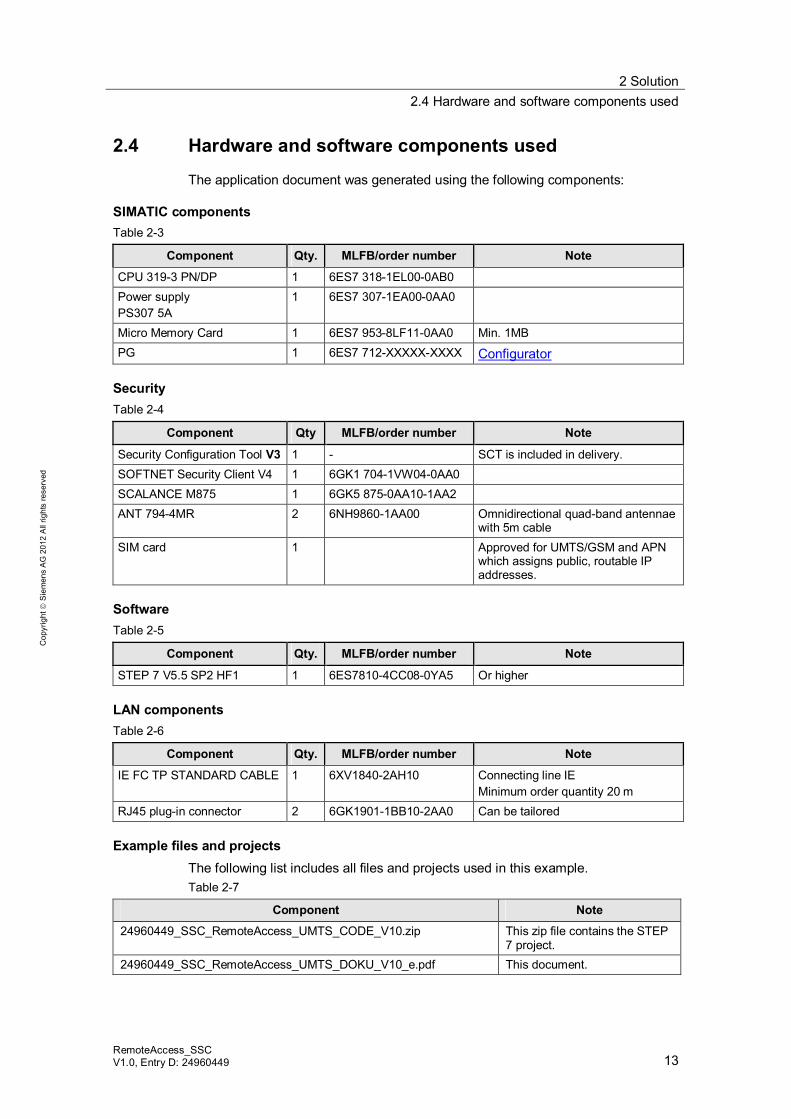
2.4 Hardware and software components used
The application document was generated using the following components:
SIMATIC components Table 2-3
Component Qty. MLFB/order number Note
CPU 319-3 PN/DP 1 6ES7 318-1EL00-0AB0 Power supply PS307 5A
1 6ES7 307-1EA00-0AA0
Micro Memory Card 1 6ES7 953-8LF11-0AA0 Min. 1MB PG 1 6ES7 712-XXXXX-XXXX Configurator
Security Table 2-4
Component Qty MLFB/order number Note
Security Configuration Tool V3 1 - SCT is included in delivery. SOFTNET Security Client V4 1 6GK1 704-1VW04-0AA0 SCALANCE M875 1 6GK5 875-0AA10-1AA2 ANT 794-4MR 2 6NH9860-1AA00 Omnidirectional quad-band antennae
with 5m cable SIM card 1 Approved for UMTS/GSM and APN
which assigns public, routable IP addresses.
Software Table 2-5
Component Qty. MLFB/order number Note
STEP 7 V5.5 SP2 HF1 1 6ES7810-4CC08-0YA5 Or higher
LAN components Table 2-6
Component Qty. MLFB/order number Note
IE FC TP STANDARD CABLE 1 6XV1840-2AH10 Connecting line IE Minimum order quantity 20 m
RJ45 plug-in connector 2 6GK1901-1BB10-2AA0 Can be tailored
Example files and projects The following list includes all files and projects used in this example. Table 2-7
Component Note
24960449_SSC_RemoteAccess_UMTS_CODE_V10.zip This zip file contains the STEP 7 project.
24960449_SSC_RemoteAccess_UMTS_DOKU_V10_e.pdf This document.
3 Basic Information 3.1 The VPN connection modes of the SCALANCE M875
14 RemoteAccess_SSC
V1.0, Entry ID: 24960449
Cop
yrig
ht
Sie
men
s A
G 2
012
All
right
s re
serv
ed
3 Basic Information 3.1 The VPN connection modes of the SCALANCE M875
The SCALANCE M875 is capable of establishing VPN connections to a remote network. The telegrams are encrypted and transmitted via IPSec in the tunnel mode. This protects data from unauthorized manipulations and confidentiality or data integrity is maintained. The remote network has to have a VPN gateway as remote station, in order for the M875 to be able to establish a VPN tunnel. For the VPN connections the SCALANCE M875 distinguishes two modes: Standard mode Roadwarrior mode
Standard mode In the standard mode the address of the peer has to be known so that the VPN connection can be established. The SCALANCE M875 can either establish the VPN connection actively as VPN client or it can wait passively for the establishment of the connection through the peer.
Roadwarrior mode In this mode the SCALANCE M875 can only act as VPN server; the module can only wait for the VPN connections but it cannot establish a VPN tunnel as an active partner. The address of the peer does not have to be known in this mode. The use of a dynamic IP address is therefore possible.
Note In this application the roadwarrior mode of the SCALANCE M875 is used.
3 Basic Information 3.2 Establishing a connection via defined norms
RemoteAccess_SSC V1.0, Entry D: 24960449 15
Cop
yrig
ht
Sie
men
s A
G 2
012
All
right
s re
serv
ed
3.2 Establishing a connection via defined norms
3.2.1 The domain name system
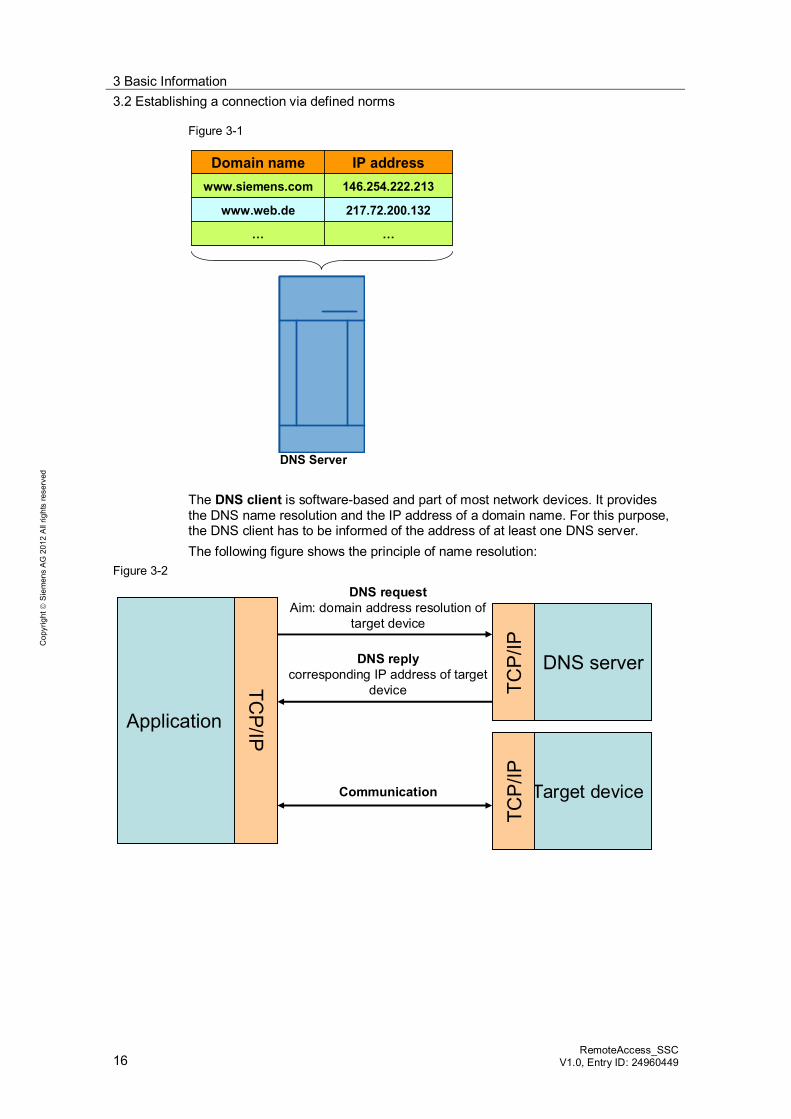
What is DNS? In IP-based networks (internet, mobile communications, local network) the access to the devices (computers, servers, mobile devices, routers etc.) is performed via their IP address. In smaller networks this can still be realized. However, on the internet the number of devices and servers is by far greater so that access via their IP address is unclear and barely memorable. For accessing the numerous devices and servers on the internet it is therefore common to use a unique name, e.g. www.siemens.com. These so called domain names are catchier but have to be translated to the respective IP addresses. This translation is mainly performed by the DNS (Domain Name System) service. For example, for www.siemens.com the IP address 146.254.222.213 is stored.
The components of DNS The DNS service integrates several components: Domain name DNS server DNS client
The domain name is used in order to give network devices which are addressed with hardly memorable IP addresses real names. Each domain name is subject to a defined structure (URL) and consists of a minimum of three parts (service, unique name, country code). To be able to find a target device on the internet, the domain name and the IP address have to be known. For this purpose databases are kept on several DNS servers that save the matching addresses.
3 Basic Information 3.2 Establishing a connection via defined norms
16 RemoteAccess_SSC
V1.0, Entry ID: 24960449
Cop
yrig
ht
Sie
men
s A
G 2
012
All
right
s re
serv
ed
Figure 3-1
DNS Server
Domain name IP addresswww.siemens.com 146.254.222.213
www.web.de 217.72.200.132
… …
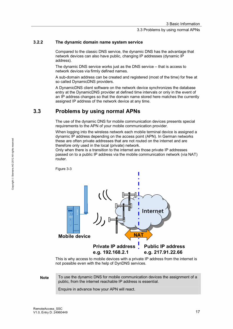
The DNS client is software-based and part of most network devices. It provides the DNS name resolution and the IP address of a domain name. For this purpose, the DNS client has to be informed of the address of at least one DNS server. The following figure shows the principle of name resolution:
Figure 3-2
Application
DNS server
Target device
TCP
/IPTC
P/IP
TCP/IP
DNS requestAim: domain address resolution of
target device
DNS replycorresponding IP address of target
device
Communication
3 Basic Information 3.3 Problems by using normal APNs
RemoteAccess_SSC V1.0, Entry D: 24960449 17
Cop
yrig
ht
Sie
men
s A
G 2
012
All
right
s re
serv
ed
3.2.2 The dynamic domain name system service
Compared to the classic DNS service, the dynamic DNS has the advantage that network devices can also have public, changing IP addresses (dynamic IP address). The dynamic DNS service works just as the DNS service – that is access to network devices via firmly defined names. A sub-domain address can be created and registered (most of the time) for free at so called DynamicDNS providers. A DynamicDNS client software on the network device synchronizes the database entry at the DynamicDNS provider at defined time intervals or only in the event of an IP address changes so that the domain name stored here matches the currently assigned IP address of the network device at any time.
3.3 Problems by using normal APNs
The use of the dynamic DNS for mobile communication devices presents special requirements to the APN of your mobile communication provider. When logging into the wireless network each mobile terminal device is assigned a dynamic IP address depending on the access point (APN). In German networks these are often private addresses that are not routed on the internet and are therefore only used in the local (private) network. Only when there is a transition to the internet are those private IP addresses passed on to a public IP address via the mobile communication network (via NAT) router. Figure 3-3
Internet
Private IP addresse.g. 192.168.2.1
Public IP addresse.g. 217.91.22.66
NATMobile device
This is why access to mobile devices with a private IP address from the internet is not possible even with the help of DynDNS services.
Note To use the dynamic DNS for mobile communication devices the assignment of a public, from the internet reachable IP address is essential.
Enquire in advance how your APN will react.
4 Installation of the Application 3.3 Problems by using normal APNs
18 RemoteAccess_SSC
V1.0, Entry ID: 24960449
Cop
yrig
ht
Sie
men
s A
G 2
012
All
right
s re
serv
ed
4 Installation of the Application Download
The STEP 7 example project is available on the HTML page from which you downloaded this document.
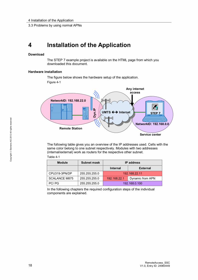
Hardware installation The figure below shows the hardware setup of the application. Figure 4-1
NetworkID: 192.168.0.0
STEP 7
Dyn
.IP
NetworkID: 192.168.22.0
UMTS Internet
Remote Station
Service center
Any internetaccess
The following table gives you an overview of the IP addresses used. Cells with the same color belong to one subnet respectively. Modules with two addresses (internal/external) work as routers for the respective other subnet. Table 4-1
Module Subnet mask IP address
Internal External
CPU319-3PN/DP 255.255.255.0 192.168.22.11 SCALANCE M875 255.255.255.0 192.168.22.1 Dynamic from APN PC/ PG 255.255.255.0 192.168.0.100
In the following chapters the required configuration steps of the individual components are explained.
4 Installation of the Application 3.3 Problems by using normal APNs
RemoteAccess_SSC V1.0, Entry D: 24960449 19
Cop
yrig
ht
Sie
men
s A
G 2
012
All
right
s re
serv
ed
Software installation The following software packages are required for this configuration: STEP 7 Security Configuration Tool V3 SOFTNET Security Client V4
Follow the instructions of the corresponding installation program.
Note This application was done with a Windows XP-PC.
If you want to install the SOFTNET Security Client on a Windows 7-PC, please pay attention to the following note: With Windows 7 the SSC uses the Windows IPsec-stack which is coupled with the firewall. The SSC doesn´t work, if the firewall is deactivated. A activated firewall is essential for the working of this application!
Installing example project Start STEP 7 and retrieve the 24960449_SSC_RemoteAccess _UMTS_CODE_V10.zip file via “File > Retrieve”.
5 Configuration of the Hardware 5.1 Networking the components
20 RemoteAccess_SSC
V1.0, Entry ID: 24960449
Cop
yrig
ht
Sie
men
s A
G 2
012
All
right
s re
serv
ed
5 Configuration of the Hardware 5.1 Networking the components
Remote station The CPU is connected in the external station via the integrated PROFINET interface with the local interface of the SCALANCE M875.
Service center In the service center the PG is connected with the internet. This can be achieved via a modem, DSL router or via a mobile communication card.
Note For the first commissioning of the individual components it is sometimes necessary to disconnect the network connection.
Pay attention to the respective notes in the configuration instructions.
5.2 Adapting the IP addresses
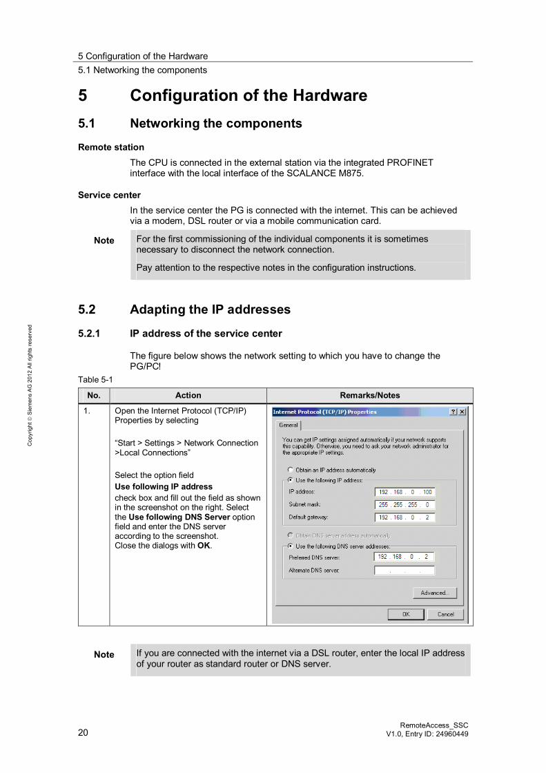
5.2.1 IP address of the service center
The figure below shows the network setting to which you have to change the PG/PC!
Table 5-1
No. Action Remarks/Notes
1. Open the Internet Protocol (TCP/IP) Properties by selecting “Start > Settings > Network Connection >Local Connections” Select the option field Use following IP address check box and fill out the field as shown in the screenshot on the right. Select the Use following DNS Server option field and enter the DNS server according to the screenshot. Close the dialogs with OK.
Note If you are connected with the internet via a DSL router, enter the local IP address of your router as standard router or DNS server.
5 Configuration of the Hardware 5.3 Loading of the remote station
RemoteAccess_SSC V1.0, Entry D: 24960449 21
Cop
yrig
ht
Sie
men
s A
G 2
012
All
right
s re
serv
ed
5.2.2 IP address of the components
Requirement In order to be able to change the IP address of a component, the following points are assumed: A PC with STEP 7 configuration software is required (e.g. the PG/PC of the
service center). The PC has to be connected directly with the component or via a switch.
SIMATIC components To load the STEP7 project to the CPU, the IP address has to be changed according to Table 4-1. For this purpose, use the SIMATIC MANAGER and the “Edit Ethernet node" option or the Primary Setup Tool (download link see \7\).
5.3 Loading of the remote station
Note The IP addresses are already preset in the STEP 7 project included in delivery (see Table 4-1). To use the project your modules have to be configured with the preset addresses.
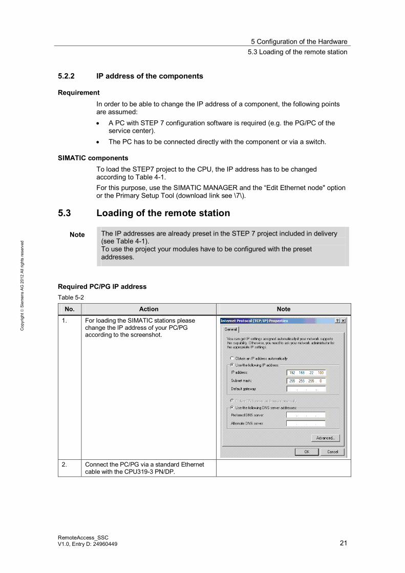
Required PC/PG IP address Table 5-2
No. Action Note
1. For loading the SIMATIC stations please change the IP address of your PC/PG according to the screenshot.
2. Connect the PC/PG via a standard Ethernet
cable with the CPU319-3 PN/DP.
5 Configuration of the Hardware 5.3 Loading of the remote station
22 RemoteAccess_SSC
V1.0, Entry ID: 24960449
Cop
yrig
ht
Sie
men
s A
G 2
012
All
right
s re
serv
ed
Loading the SIMATIC station Table 5-3
No. Action Note
1. Select the SIMATIC 300 station (RemoteStation) in the SIMATIC Manager and load it via “PLC > Download” to the CPU.
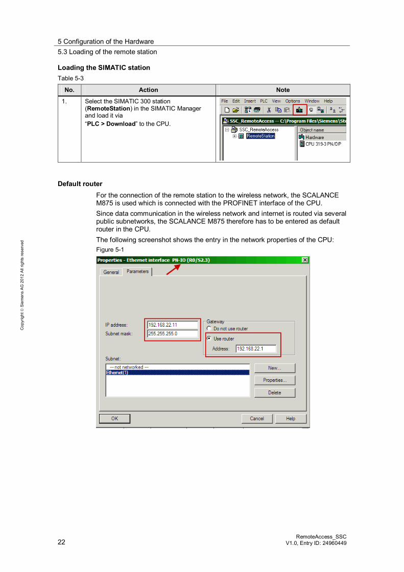
Default router For the connection of the remote station to the wireless network, the SCALANCE M875 is used which is connected with the PROFINET interface of the CPU. Since data communication in the wireless network and internet is routed via several public subnetworks, the SCALANCE M875 therefore has to be entered as default router in the CPU. The following screenshot shows the entry in the network properties of the CPU: Figure 5-1
5 Configuration of the Hardware 5.4 Commissioning of VPN tunnels
RemoteAccess_SSC V1.0, Entry D: 24960449 23
Cop
yrig
ht
Sie
men
s A
G 2
012
All
right
s re
serv
ed
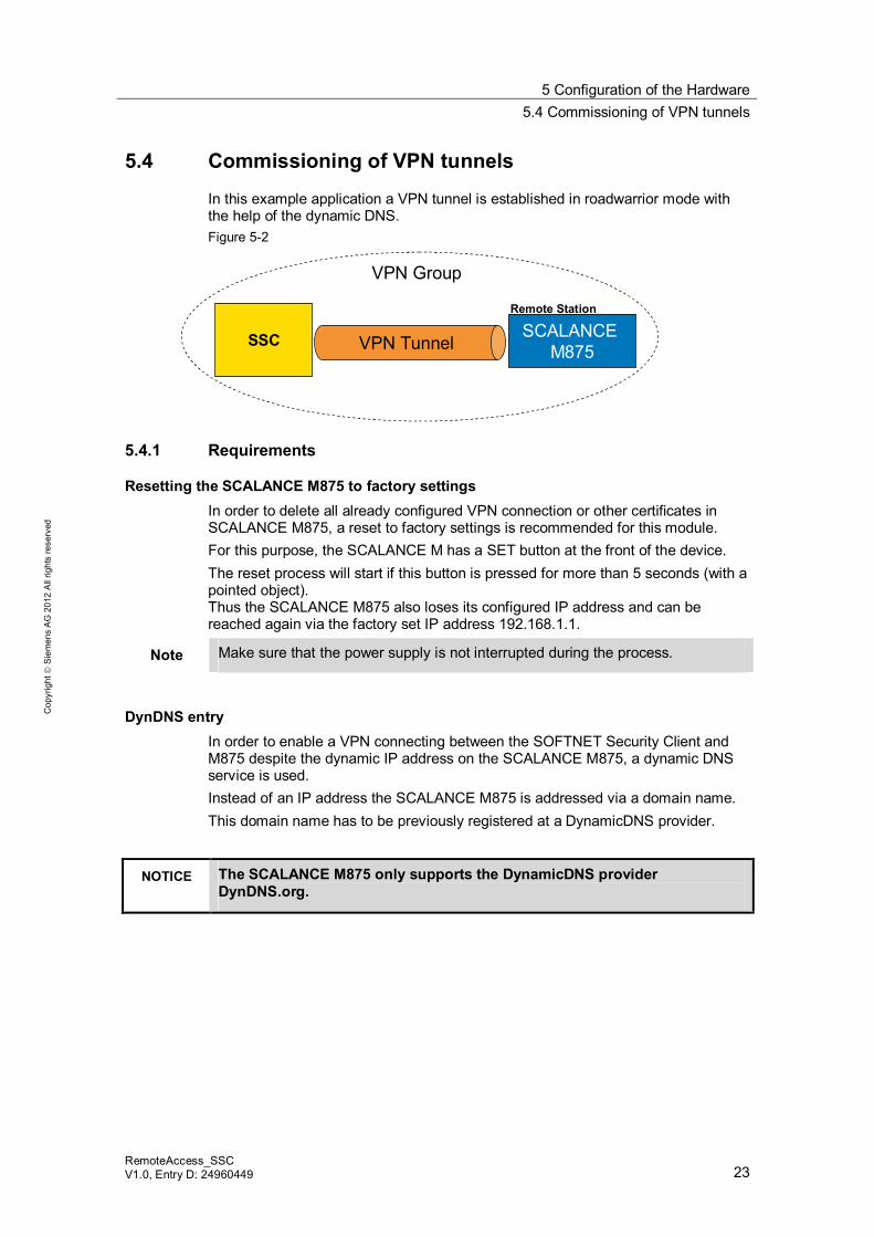
5.4 Commissioning of VPN tunnels
In this example application a VPN tunnel is established in roadwarrior mode with the help of the dynamic DNS. Figure 5-2
SCALANCE M875
Remote Station
SSC VPN Tunnel
VPN Group
5.4.1 Requirements
Resetting the SCALANCE M875 to factory settings In order to delete all already configured VPN connection or other certificates in SCALANCE M875, a reset to factory settings is recommended for this module. For this purpose, the SCALANCE M has a SET button at the front of the device. The reset process will start if this button is pressed for more than 5 seconds (with a pointed object). Thus the SCALANCE M875 also loses its configured IP address and can be reached again via the factory set IP address 192.168.1.1.
Note Make sure that the power supply is not interrupted during the process.
DynDNS entry In order to enable a VPN connecting between the SOFTNET Security Client and M875 despite the dynamic IP address on the SCALANCE M875, a dynamic DNS service is used. Instead of an IP address the SCALANCE M875 is addressed via a domain name. This domain name has to be previously registered at a DynamicDNS provider.
NOTICE The SCALANCE M875 only supports the DynamicDNS provider DynDNS.org.
5 Configuration of the Hardware 5.4 Commissioning of VPN tunnels
24 RemoteAccess_SSC
V1.0, Entry ID: 24960449
Cop
yrig
ht
Sie
men
s A
G 2
012
All
right
s re
serv
ed
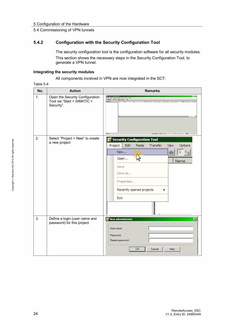
5.4.2 Configuration with the Security Configuration Tool
The security configuration tool is the configuration software for all security modules. This section shows the necessary steps in the Security Configuration Tool, to generate a VPN tunnel.
Integrating the security modules All components involved in VPN are now integrated in the SCT:
Table 5-4
No. Action Remarks
1. Open the Security Configuration Tool via “Start > SIMATIC > Security”.
2. Select “Project > New” to create
a new project.
3. Define a login (user name and
password) for this project.
5 Configuration of the Hardware 5.4 Commissioning of VPN tunnels
RemoteAccess_SSC V1.0, Entry D: 24960449 25
Cop
yrig
ht
Sie
men
s A
G 2
012
All
right
s re
serv
ed
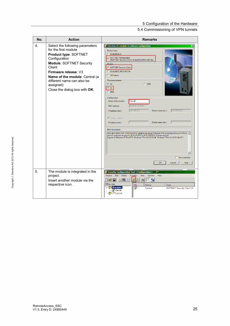
No. Action Remarks
4. Select the following parameters for the first module Product type: SOFTNET Configuration Module: SOFTNET Security Client Firmware release: V3 Name of the module: Central (a different name can also be assigned) Close the dialog box with OK.
5. The module is integrated in the
project. Insert another module via the respective icon.
5 Configuration of the Hardware 5.4 Commissioning of VPN tunnels
26 RemoteAccess_SSC
V1.0, Entry ID: 24960449
Cop
yrig
ht
Sie
men
s A
G 2
012
All
right
s re
serv
ed
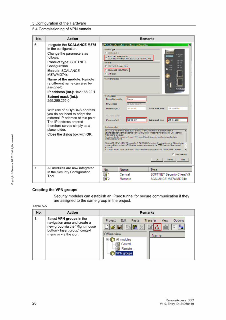
No. Action Remarks
6. Integrate the SCALANCE M875 in the configuration. Change the parameters as follows: Product type: SOFTNET Configuration Module: SCALANCE M87x/MD74x Name of the module: Remote (a different name can also be assigned) IP address (int.): 192.168.22.1 Subnet mask (int.): 255.255.255.0 With use of a DynDNS address you do not need to adapt the external IP address at this point. The IP address entered therefore serves simply as a placeholder. Close the dialog box with OK.
7. All modules are now integrated
in the Security Configuration Tool.
Creating the VPN groups Security modules can establish an IPsec tunnel for secure communication if they are assigned to the same group in the project.
Table 5-5
No. Action Remarks
1. Select VPN groups in the navigation area and create a new group via the “Right mouse button> Insert group” context menu or via the icon.
5 Configuration of the Hardware 5.4 Commissioning of VPN tunnels
RemoteAccess_SSC V1.0, Entry D: 24960449 27
Cop
yrig
ht
Sie
men
s A
G 2
012
All
right
s re
serv
ed
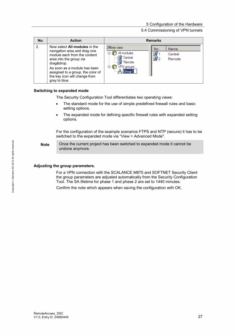
No. Action Remarks
2. Now select All modules in the navigation area and drag one module each from the content area into the group via drag&drop. As soon as a module has been assigned to a group, the color of the key icon will change from gray to blue.
Switching to expanded mode The Security Configuration Tool differentiates two operating views: The standard mode for the use of simple predefined firewall rules and basic
setting options. The expanded mode for defining specific firewall rules with expanded setting
options. For the configuration of the example scenarios FTPS and NTP (secure) it has to be switched to the expanded mode via “View > Advanced Mode".
Note Once the current project has been switched to expanded mode it cannot be undone anymore.
Adjusting the group parameters. For a VPN connection with the SCALANCE M875 and SOFTNET Security Client the group parameters are adjusted automatically from the Security Configuration Tool. The SA lifetime for phase 1 and phase 2 are set to 1440 minutes. Confirm the note which appears when saving the configuration with OK.
5 Configuration of the Hardware 5.4 Commissioning of VPN tunnels
28 RemoteAccess_SSC
V1.0, Entry ID: 24960449
Cop
yrig
ht
Sie
men
s A
G 2
012
All
right
s re
serv
ed
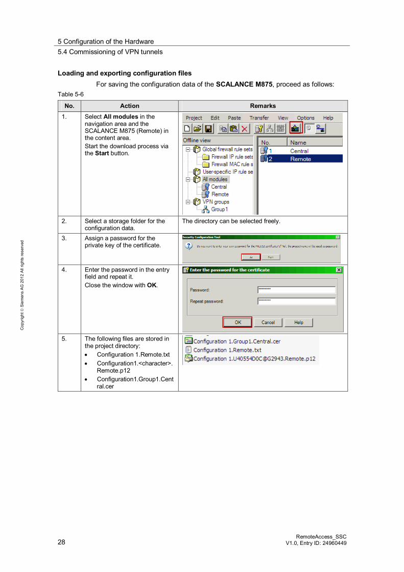
Loading and exporting configuration files For saving the configuration data of the SCALANCE M875, proceed as follows:
Table 5-6
No. Action Remarks
1. Select All modules in the navigation area and the SCALANCE M875 (Remote) in the content area. Start the download process via the Start button.
2. Select a storage folder for the
configuration data. The directory can be selected freely.
3. Assign a password for the private key of the certificate.
4. Enter the password in the entry
field and repeat it. Close the window with OK.
5. The following files are stored in
the project directory: Configuration 1.Remote.txt Configuration1.<character>.
Remote.p12 Configuration1.Group1.Cent
ral.cer
5 Configuration of the Hardware 5.4 Commissioning of VPN tunnels
RemoteAccess_SSC V1.0, Entry D: 24960449 29
Cop
yrig
ht
Sie
men
s A
G 2
012
All
right
s re
serv
ed
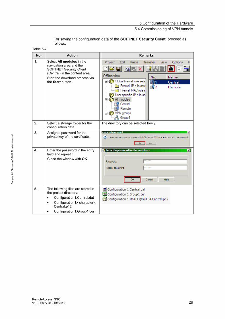
For saving the configuration data of the SOFTNET Security Client, proceed as follows:
Table 5-7
No. Action Remarks
1. Select All modules in the navigation area and the SOFTNET Security Client (Central) in the content area. Start the download process via the Start button.
2. Select a storage folder for the
configuration data. The directory can be selected freely.
3. Assign a password for the private key of the certificate.
4. Enter the password in the entry
field and repeat it. Close the window with OK.
5. The following files are stored in
the project directory: Configuration1.Central.dat Configuration1.<character>.
Central.p12 Configuration1.Group1.cer
5 Configuration of the Hardware 5.5 Configuration of the SCALANCE M875
30 RemoteAccess_SSC
V1.0, Entry ID: 24960449
Cop
yrig
ht
Sie
men
s A
G 2
012
All
right
s re
serv
ed
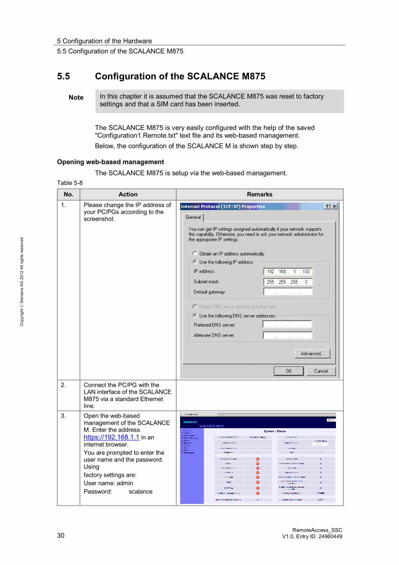
5.5 Configuration of the SCALANCE M875
Note In this chapter it is assumed that the SCALANCE M875 was reset to factory settings and that a SIM card has been inserted.
The SCALANCE M875 is very easily configured with the help of the saved "Configuration1.Remote.txt" text file and its web-based management. Below, the configuration of the SCALANCE M is shown step by step.
Opening web-based management The SCALANCE M875 is setup via the web-based management.
Table 5-8
No. Action Remarks
1. Please change the IP address of your PC/PGs according to the screenshot.
2. Connect the PC/PG with the
LAN interface of the SCALANCE M875 via a standard Ethernet line.
3. Open the web-based management of the SCALANCE M. Enter the address https://192.168.1.1 in an internet browser. You are prompted to enter the user name and the password. Using factory settings are: User name: admin Password: scalance
5 Configuration of the Hardware 5.5 Configuration of the SCALANCE M875
RemoteAccess_SSC V1.0, Entry D: 24960449 31
Cop
yrig
ht
Sie
men
s A
G 2
012
All
right
s re
serv
ed
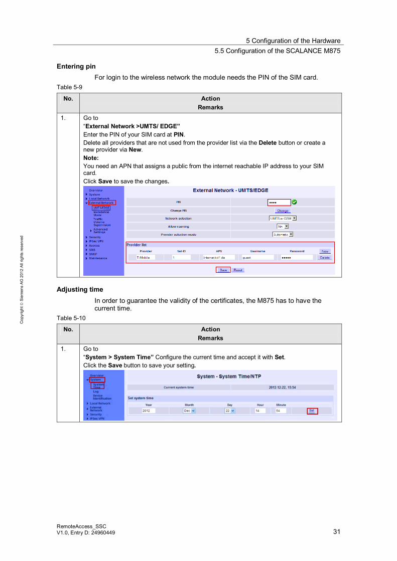
Entering pin For login to the wireless network the module needs the PIN of the SIM card.
Table 5-9
No. Action Remarks
1. Go to “External Network >UMTS/ EDGE” Enter the PIN of your SIM card at PIN. Delete all providers that are not used from the provider list via the Delete button or create a new provider via New. Note: You need an APN that assigns a public from the internet reachable IP address to your SIM card. Click Save to save the changes.
Adjusting time In order to guarantee the validity of the certificates, the M875 has to have the current time.
Table 5-10
No. Action Remarks
1. Go to “System > System Time” Configure the current time and accept it with Set. Click the Save button to save your setting.
5 Configuration of the Hardware 5.5 Configuration of the SCALANCE M875
32 RemoteAccess_SSC
V1.0, Entry ID: 24960449
Cop
yrig
ht
Sie
men
s A
G 2
012
All
right
s re
serv
ed
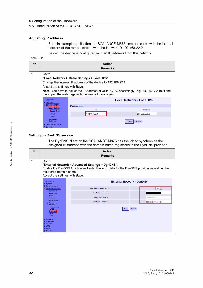
Adjusting IP address For this example application the SCALANCE M875 communicates with the internal network of the remote station with the NetworkID 192.168.22.0. Below, the device is configured with an IP address from this network.
Table 5-11
No. Action Remarks
1. Go to “Local Network > Basic Settings > Local IPs” Change the internal IP address of the device to 192.168.22.1 Accept the settings with Save. Note: You have to adjust the IP address of your PC/PG accordingly (e.g. 192.168.22.100) and then open the web page with the new address again.
Setting up DynDNS service The DynDNS client on the SCALANCE M875 has the job to synchronize the assigned IP address with the domain name registered in the DynDNS provider.
No. Action Remarks
1. Go to "External Network > Advanced Settings > DynDNS". Enable the DynDNS function and enter the login data for the DynDNS provider as well as the registered domain name. Accept the settings with Save.
5 Configuration of the Hardware 5.5 Configuration of the SCALANCE M875
RemoteAccess_SSC V1.0, Entry D: 24960449 33
Cop
yrig
ht
Sie
men
s A
G 2
012
All
right
s re
serv
ed
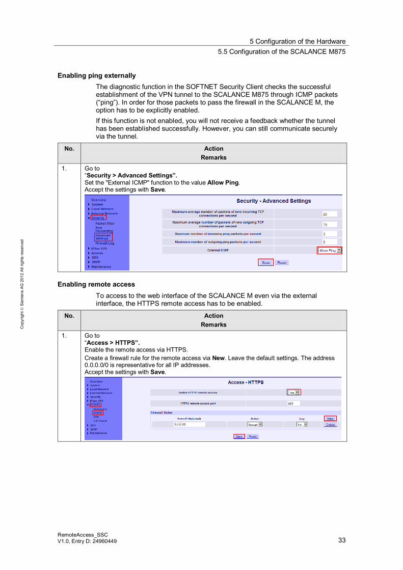
Enabling ping externally The diagnostic function in the SOFTNET Security Client checks the successful establishment of the VPN tunnel to the SCALANCE M875 through ICMP packets (“ping”). In order for those packets to pass the firewall in the SCALANCE M, the option has to be explicitly enabled. If this function is not enabled, you will not receive a feedback whether the tunnel has been established successfully. However, you can still communicate securely via the tunnel.
No. Action Remarks
1. Go to “Security > Advanced Settings”. Set the "External ICMP" function to the value Allow Ping. Accept the settings with Save.
Enabling remote access To access to the web interface of the SCALANCE M even via the external interface, the HTTPS remote access has to be enabled.
No. Action Remarks
1. Go to “Access > HTTPS”. Enable the remote access via HTTPS. Create a firewall rule for the remote access via New. Leave the default settings. The address 0.0.0.0/0 is representative for all IP addresses. Accept the settings with Save.
5 Configuration of the Hardware 5.5 Configuration of the SCALANCE M875
34 RemoteAccess_SSC
V1.0, Entry ID: 24960449
Cop
yrig
ht
Sie
men
s A
G 2
012
All
right
s re
serv
ed
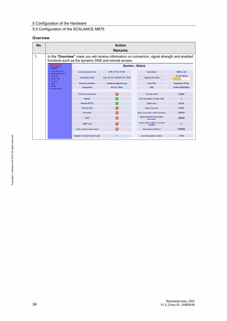
Overview
No. Action Remarks
1. In the “Overview” mask you will receive information on connection, signal strength and enabled functions such as the dynamic DNS and remote access.
5 Configuration of the Hardware 5.5 Configuration of the SCALANCE M875
RemoteAccess_SSC V1.0, Entry D: 24960449 35
Cop
yrig
ht
Sie
men
s A
G 2
012
All
right
s re
serv
ed
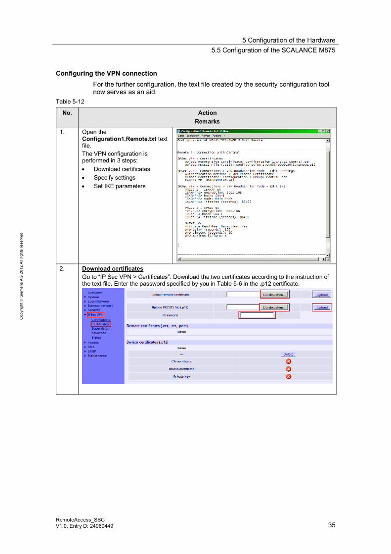
Configuring the VPN connection For the further configuration, the text file created by the security configuration tool now serves as an aid.
Table 5-12
No. Action Remarks
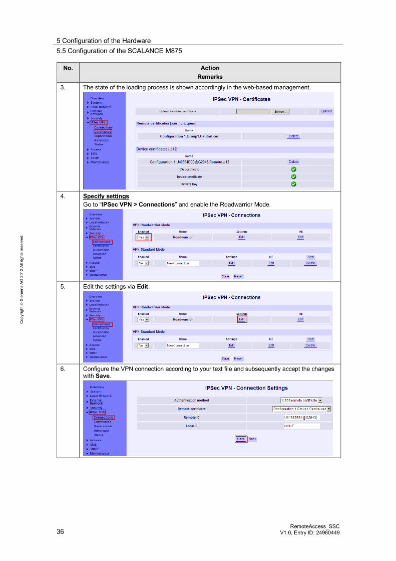
1. Open the Configuration1.Remote.txt text file. The VPN configuration is performed in 3 steps: Download certificates Specify settings Set IKE parameters
2. Download certificates
Go to “IP Sec VPN > Certificates”. Download the two certificates according to the instruction of the text file. Enter the password specified by you in Table 5-6 in the .p12 certificate.
5 Configuration of the Hardware 5.5 Configuration of the SCALANCE M875
36 RemoteAccess_SSC
V1.0, Entry ID: 24960449
Cop
yrig
ht
Sie
men
s A
G 2
012
All
right
s re
serv
ed
No. Action Remarks
3. The state of the loading process is shown accordingly in the web-based management.
4. Specify settings
Go to “IPSec VPN > Connections” and enable the Roadwarrior Mode.
5. Edit the settings via Edit.
6. Configure the VPN connection according to your text file and subsequently accept the changes
with Save.
5 Configuration of the Hardware 5.5 Configuration of the SCALANCE M875
RemoteAccess_SSC V1.0, Entry D: 24960449 37
Cop
yrig
ht
Sie
men
s A
G 2
012
All
right
s re
serv
ed
No. Action Remarks
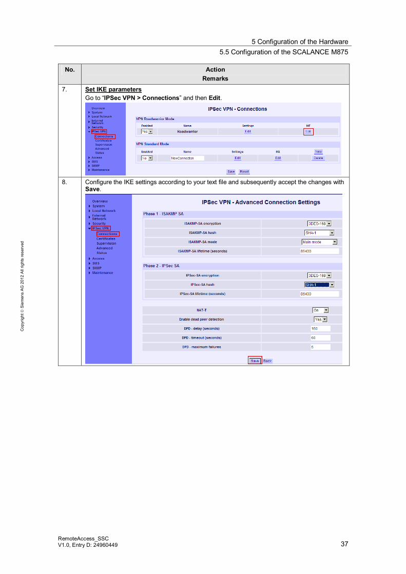
7. Set IKE parameters Go to “IPSec VPN > Connections” and then Edit.
8. Configure the IKE settings according to your text file and subsequently accept the changes with
Save.
5 Configuration of the Hardware 5.5 Configuration of the SCALANCE M875
38 RemoteAccess_SSC
V1.0, Entry ID: 24960449
Cop
yrig
ht
Sie
men
s A
G 2
012
All
right
s re
serv
ed
Hinweis A successful tunnel connection between a SCALANCE M and the SOFTNET Security Client can only be established if you keep exactly to the following parameters. If you use different parameter settings, it is possible that the two tunnel partners will not be able to set up a VPN connection between them.
Authentication method: Certificate
Advanced Settings Phase 1:
IKE mode: Main Phase 1 DH group: Group2 Phase 1 Encryption: 3DES-168 SA lifetime (minutes): 1440 minutes Phase 1 Authentication: SHA1
Advanced Settings Phase 2:
SA lifetime type: Time Phase 2 Encryption: 3DES-168 SA lifetime: 1440 minutes Phase 2 Authentication: SHA1
5 Configuration of the Hardware 5.6 Configuration of the SOFTNET Security Client
RemoteAccess_SSC V1.0, Entry D: 24960449 39
Cop
yrig
ht
Sie
men
s A
G 2
012
All
right
s re
serv
ed
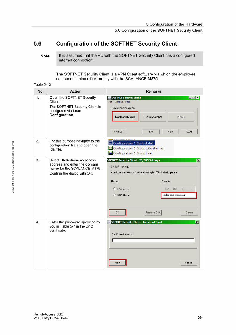
5.6 Configuration of the SOFTNET Security Client
Note It is assumed that the PC with the SOFTNET Security Client has a configured internet connection.
The SOFTNET Security Client is a VPN Client software via which the employee can connect himself externally with the SCALANCE M875.
Table 5-13
No. Action Remarks
1. Open the SOFTNET Security Client. The SOFTNET Security Client is configured via Load Configuration.
2. For this purpose navigate to the
configuration file and open the .dat file.
3. Select DNS-Name as access
address and enter the domain name for the SCALANCE M875. Confirm the dialog with OK.
4. Enter the password specified by
you in Table 5-7 in the .p12 certificate.
5 Configuration of the Hardware 5.7 Final configuration
40 RemoteAccess_SSC
V1.0, Entry ID: 24960449
Cop
yrig
ht
Sie
men
s A
G 2
012
All
right
s re
serv
ed
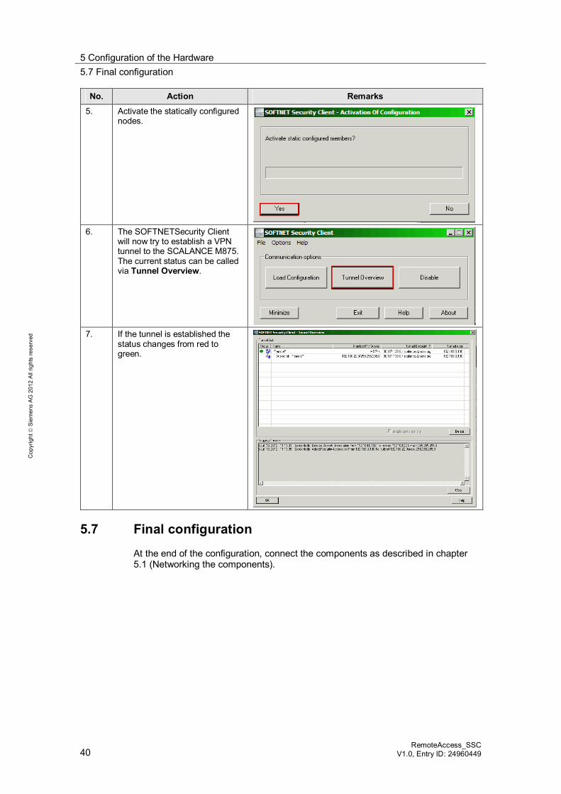
No. Action Remarks
5. Activate the statically configured nodes.
6. The SOFTNETSecurity Client
will now try to establish a VPN tunnel to the SCALANCE M875. The current status can be called via Tunnel Overview.
7. If the tunnel is established the
status changes from red to green.
5.7 Final configuration
At the end of the configuration, connect the components as described in chapter 5.1 (Networking the components).
6 Operating the Application 6.1 Scenario: Standard STEP 7 PG and online functions
RemoteAccess_SSC V1.0, Entry D: 24960449 41
Cop
yrig
ht
Sie
men
s A
G 2
012
All
right
s re
serv
ed
6 Operating the Application Requirement
For the operation of these scenarios, the following requirements apply: The IP addresses of the components have to be configured according to Table
4-1. The final configuration has to be completed as described in chapter 5.7 (Final
configuration).
Scenarios This chapter shows the following functionalities according to selected scenarios: Standard STEP 7 PG and online functions HTML-based access to the web server of the CPU.
6.1 Scenario: Standard STEP 7 PG and online functions
Description In this scenario the following items are shown: All online system diagnostic functions (diagnostic buffer of the CPU, module
state, operating state, monitoring/controlling, etc.) based on Layer 3. Controlling and monitoring of variables. Download and upload of the STEP 7 program.
Online system functions Table 6-1
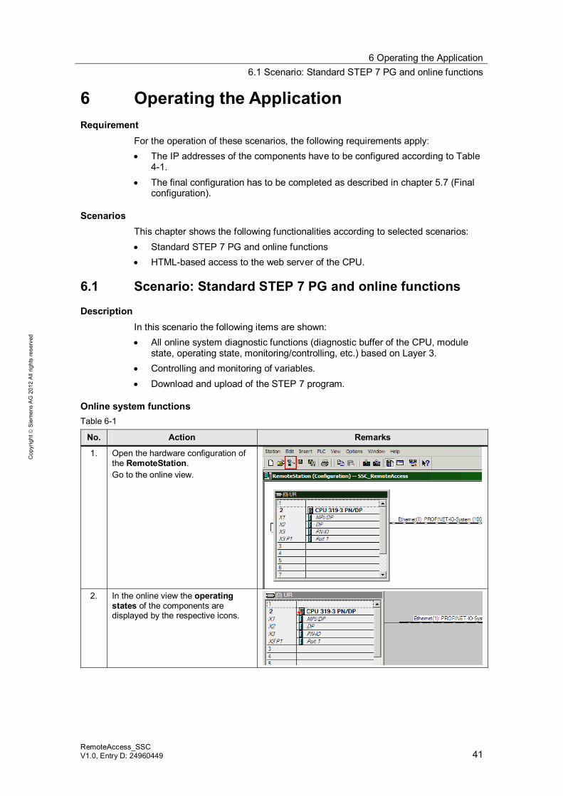
No. Action Remarks
1. Open the hardware configuration of the RemoteStation. Go to the online view.
2. In the online view the operating
states of the components are displayed by the respective icons.
6 Operating the Application 6.1 Scenario: Standard STEP 7 PG and online functions
42 RemoteAccess_SSC
V1.0, Entry ID: 24960449
Cop
yrig
ht
Sie
men
s A
G 2
012
All
right
s re
serv
ed
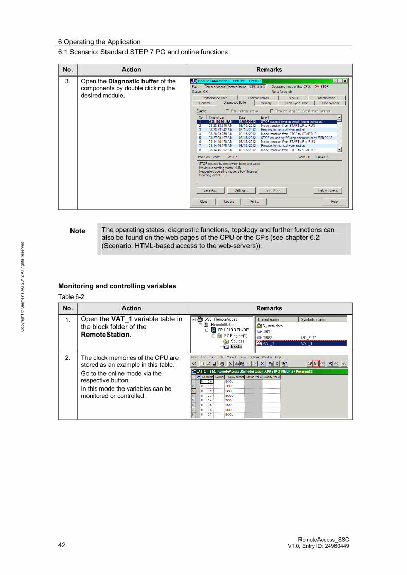
No. Action Remarks
3. Open the Diagnostic buffer of the components by double clicking the desired module.
Note The operating states, diagnostic functions, topology and further functions can also be found on the web pages of the CPU or the CPs (see chapter 6.2 (Scenario: HTML-based access to the web-servers)).
Monitoring and controlling variables Table 6-2
No. Action Remarks
1. Open the VAT_1 variable table in the block folder of the RemoteStation.
2. The clock memories of the CPU are
stored as an example in this table. Go to the online mode via the respective button. In this mode the variables can be monitored or controlled.
6 Operating the Application 6.1 Scenario: Standard STEP 7 PG and online functions
RemoteAccess_SSC V1.0, Entry D: 24960449 43
Cop
yrig
ht
Sie
men
s A
G 2
012
All
right
s re
serv
ed
Upload and download of the STEP 7 program Table 6-3
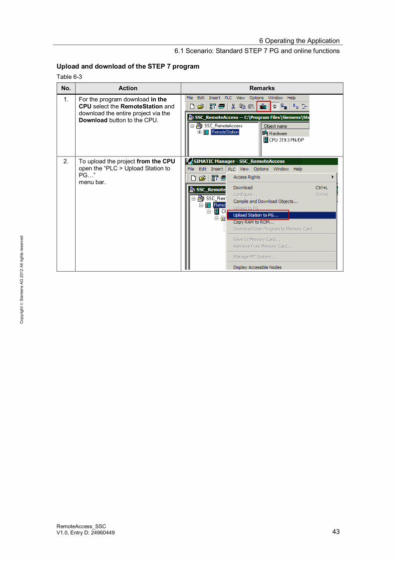
No. Action Remarks
1. For the program download in the CPU select the RemoteStation and download the entire project via the Download button to the CPU.
2. To upload the project from the CPU
open the “PLC > Upload Station to PG…” menu bar.
6 Operating the Application 6.2 Scenario: HTML-based access to the web-servers
44 RemoteAccess_SSC
V1.0, Entry ID: 24960449
Cop
yrig
ht
Sie
men
s A
G 2
012
All
right
s re
serv
ed
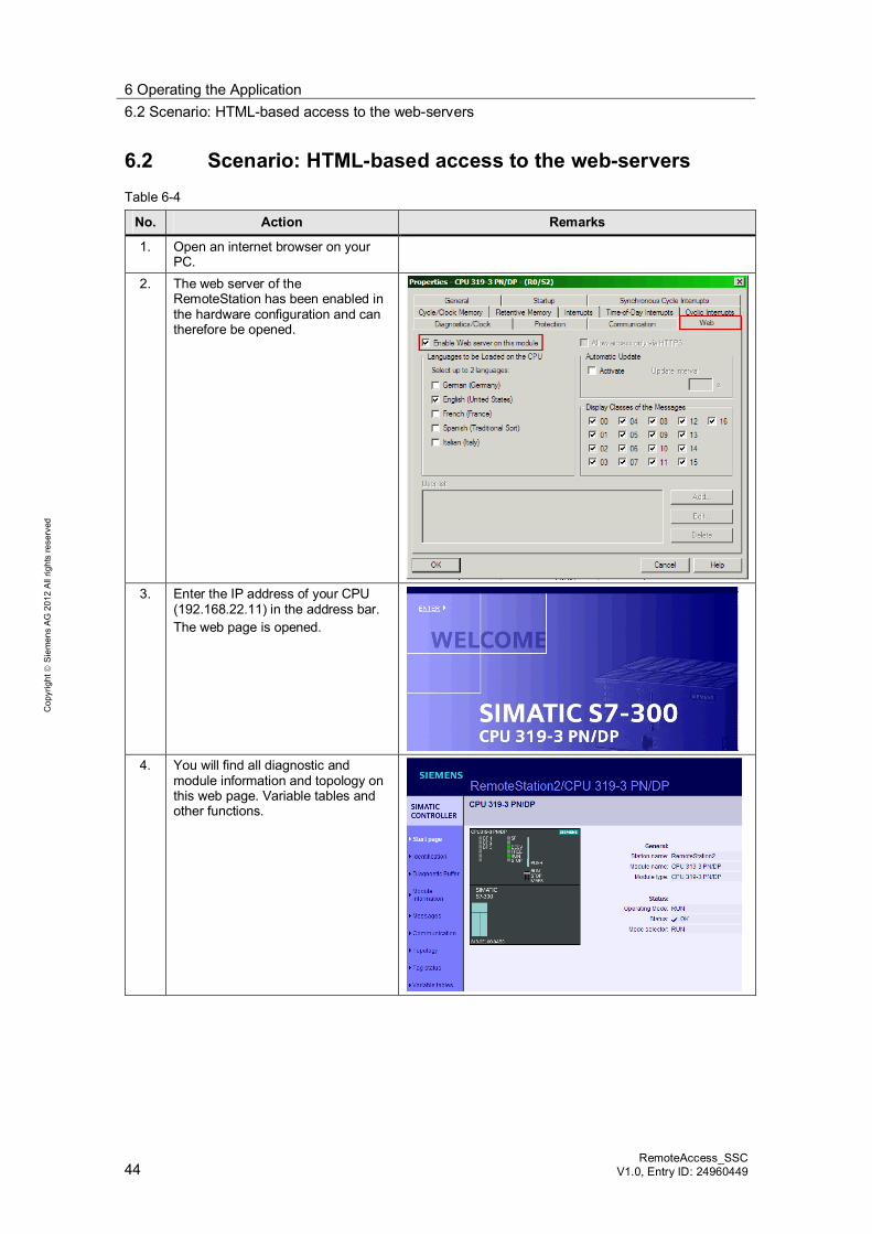
6.2 Scenario: HTML-based access to the web-servers Table 6-4
No. Action Remarks
1. Open an internet browser on your PC.
2. The web server of the RemoteStation has been enabled in the hardware configuration and can therefore be opened.
3. Enter the IP address of your CPU
(192.168.22.11) in the address bar. The web page is opened.
4. You will find all diagnostic and
module information and topology on this web page. Variable tables and other functions.
7 Literature
RemoteAccess_SSC V1.0, Entry D: 24960449 45
Cop
yrig
ht
Sie
men
s A
G 2
012
All
right
s re
serv
ed
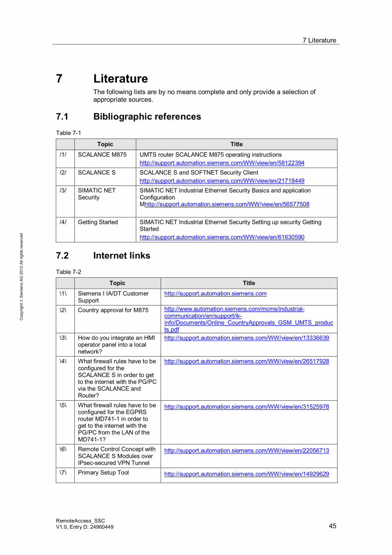
7 Literature The following lists are by no means complete and only provide a selection of appropriate sources.
7.1 Bibliographic references Table 7-1
Topic Title
/1/ SCALANCE M875 UMTS router SCALANCE M875 operating instructions http://support.automation.siemens.com/WW/view/en/58122394
/2/ SCALANCE S SCALANCE S and SOFTNET Security Client http://support.automation.siemens.com/WW/view/en/21718449
/3/ SIMATIC NET Security
SIMATIC NET Industrial Ethernet Security Basics and application Configuration Mhttp://support.automation.siemens.com/WW/view/en/56577508
/4/ Getting Started SIMATIC NET Industrial Ethernet Security Setting up security Getting Started http://support.automation.siemens.com/WW/view/en/61630590
7.2 Internet links Table 7-2
Topic Title
\1\ Siemens I IA/DT Customer Support
http://support.automation.siemens.com
\2\ Country approval for M875 http://www.automation.siemens.com/mcms/industrial-communication/en/support/ik-info/Documents/Online_CountryApprovals_GSM_UMTS_products.pdf
\3\ How do you integrate an HMI operator panel into a local network?
http://support.automation.siemens.com/WW/view/en/13336639
\4\ What firewall rules have to be configured for the SCALANCE S in order to get to the internet with the PG/PC via the SCALANCE and Router?
http://support.automation.siemens.com/WW/view/en/26517928
\5\ What firewall rules have to be configured for the EGPRS router MD741-1 in order to get to the internet with the PG/PC from the LAN of the MD741-1?
http://support.automation.siemens.com/WW/view/en/31525978
\6\ Remote Control Concept with SCALANCE S Modules over IPsec-secured VPN Tunnel
http://support.automation.siemens.com/WW/view/en/22056713
\7\ Primary Setup Tool http://support.automation.siemens.com/WW/view/en/14929629

8 History
46 RemoteAccess_SSC
V1.0, Entry ID: 24960449
Cop
yrig
ht
Sie
men
s A
G 2
012
All
right
s re
serv
ed
8 History Table 8-1 History
Version Date Revisions
V1.0 01.08.2012 First issue