Embed Size (px)
Citation preview
Security Products
Secure Services Gateway (SSG) 20Hardware Installation and Configuration Guide
ScreenOS 5.4.0
Juniper Networks, Inc.
1194 North Mathilda Avenue
Sunnyvale, CA 94089
USA
408-745-2000
www.juniper.net
Part Number: 530-015646-01, Revision A

2
Copyright Notice
Copyright © 2006 Juniper Networks, Inc. All rights reserved.
Juniper Networks and the Juniper Networks logo are registered trademarks of Juniper Networks, Inc. in the United States and other countries. All other trademarks, service marks, registered trademarks, or registered service marks in this document are the property of Juniper Networks or their respective owners. All specifications are subject to change without notice. Juniper Networks assumes no responsibility for any inaccuracies in this document or for any obligation to update information in this document. Juniper Networks reserves the right to change, modify, transfer, or otherwise revise this publication without notice.
FCC Statement
The following information is for FCC compliance of Class A devices: This equipment has been tested and found to comply with the limits for a Class A digital device, pursuant to part 15 of the FCC rules. These limits are designed to provide reasonable protection against harmful interference when the equipment is operated in a commercial environment. The equipment generates, uses, and can radiate radio-frequency energy and, if not installed and used in accordance with the instruction manual, may cause harmful interference to radio communications. Operation of this equipment in a residential area is likely to cause harmful interference, in which case users will be required to correct the interference at their own expense.
The following information is for FCC compliance of Class B devices: The equipment described in this manual generates and may radiate radio-frequency energy. If it is not installed in accordance with Juniper Networks’ installation instructions, it may cause interference with radio and television reception. This equipment has been tested and found to comply with the limits for a Class B digital device in accordance with the specifications in part 15 of the FCC rules. These specifications are designed to provide reasonable protection against such interference in a residential installation. However, there is no guarantee that interference will not occur in a particular installation.
If this equipment does cause harmful interference to radio or television reception, which can be determined by turning the equipment off and on, the user is encouraged to try to correct the interference by one or more of the following measures:
Reorient or relocate the receiving antenna.
Increase the separation between the equipment and receiver.
Consult the dealer or an experienced radio/TV technician for help.
Connect the equipment to an outlet on a circuit different from that to which the receiver is connected.
Caution: Changes or modifications to this product could void the user's warranty and authority to operate this device.
Disclaimer
THE SOFTWARE LICENSE AND LIMITED WARRANTY FOR THE ACCOMPANYING PRODUCT ARE SET FORTH IN THE INFORMATION PACKET THAT SHIPPED WITH THE PRODUCT AND ARE INCORPORATED HEREIN BY THIS REFERENCE. IF YOU ARE UNABLE TO LOCATE THE SOFTWARE LICENSE OR LIMITED WARRANTY, CONTACT YOUR JUNIPER NETWORKS REPRESENTATIVE FOR A COPY.

Table of Contents
About This Guide 7
Organization ....................................................................................................7WebUI Conventions .........................................................................................8CLI Conventions...............................................................................................8Obtaining Documentation and Technical Support ............................................9
Chapter 1 Hardware Overview 11
Port and Power Connectors ...........................................................................12Front Panel ....................................................................................................13
System Status LEDs .................................................................................13Port Descriptions .....................................................................................14
Ethernet Ports ...................................................................................15Console Port .....................................................................................15AUX Port...........................................................................................15
Mini Physical Interface Module Port Descriptions ....................................16Back Panel .....................................................................................................18
Power Adapter.........................................................................................18Radio Transceivers ..................................................................................18Grounding Lug.........................................................................................18Antennae Types.......................................................................................19Universal Serial Bus Host Module ............................................................19
Chapter 2 Installing and Connecting the Device 21
Before You Begin ...........................................................................................21Equipment Installation ...................................................................................22Connecting the Interface Cable to a Device....................................................23Connecting the Power....................................................................................23Connecting the Device to a Network ..............................................................23
Connecting an SSG 20 Device to an Untrusted Network ..........................24Connecting Ethernet Ports ................................................................24Connecting Serial AUX/Console Ports................................................24
Connecting Mini PIMs to an Untrusted Network ......................................25ADSL2/2+ Mini PIM .........................................................................25ISDN, T1, E1, and V.92 Mini PIMs.....................................................26
Connecting the Device to an Internal Network or a Workstation .............26Connecting Ethernet Ports ................................................................26Connecting the Wireless Antennae....................................................26
Chapter 3 Configuring the Device 27
Access the Device ..........................................................................................28Using a Console Connection ....................................................................28Using the WebUI .....................................................................................29
Table of Contents 3
4
SSG 20 Hardware Installation and Configuration Guide
Using Telnet ............................................................................................30Default Device Settings ..................................................................................31Basic Device Configuration ............................................................................33
Changing the Root Admin Name and Password ......................................33Setting the Date and Time .......................................................................34Bridge Group Interfaces ...........................................................................34Administrative Access .............................................................................35Management Services..............................................................................35Host and Domain Name ..........................................................................36Default Route...........................................................................................36Management Interface Address ...............................................................36Backup Untrust Interface Configuration...................................................37
Wireless Configuration...................................................................................37Wireless Network Configuration ..............................................................38
Wireless Configuration Example .......................................................39Authentication and Encryption..........................................................41
Mini PIM Configuration ..................................................................................41Asymmetrical DSL (ADSL) 2/2+ Interface ...............................................41
Virtual Circuits to an ADSL2/2+ Interface.........................................42VPI/VCI and Multiplexing Method......................................................43PPPoE or PPPoA ...............................................................................43Static IP Address and Netmask..........................................................44
ISDN Interface .........................................................................................45T1 Interface .............................................................................................46E1 Interface .............................................................................................47V.92 Modem Interface .............................................................................48
Basic Firewall Protections ..............................................................................49Verifying External Connectivity......................................................................49Resetting the Device to Factory Defaults ........................................................50
The Reset Pinhole....................................................................................50
Chapter 4 Servicing the Device 53
Required Tools and Parts ...............................................................................53Replacing a Physical Interface Module ...........................................................53
Removing a Blank Faceplate....................................................................54Removing a Mini PIM ..............................................................................54Installing a Mini PIM................................................................................55
Memory Upgrade ...........................................................................................56
Appendix A Specifications 59
SSG 20 Physical Specifications .......................................................................59Electrical Specification ...................................................................................59Environmental ...............................................................................................60Certifications..................................................................................................60
Safety ......................................................................................................60EMC (Emissions)......................................................................................60EMC Immunity ........................................................................................60European Telecommunications Standards Institute (ETSI) .......................61T1 Interface .............................................................................................61
Connectors.....................................................................................................61
Table of Contents

Table of Contents
Appendix B Initial Configuration Wizard 65
Index.......................................................................................................................... 85
Table of Contents 5

6
SSG 20 Hardware Installation and Configuration Guide
Table of Contents

About This Guide
The Juniper Networks Secure Services Gateway (SSG) 20 device is an integrated router and firewall platform that provides Internet Protocol Security (IPSec) Virtual Private Network (VPN) and firewall services for a branch office or a retail outlet.
Juniper Networks offers two models of the SSG 20 device:
SSG 20 which supports auxiliary (AUX)
SSG 20-WLAN which supports integrated 802.11a/b/g wireless standards
Both of the SSG 20 devices support universal storage bus (USB) storage and two mini physical interface module (PIM) slots that can hold any of the mini PIMs. The devices also provide protocol conversions between local area networks (LANs) and wide area networks (WANs).
Organization
This guide contains the following chapters:
Chapter 1, “Hardware Overview,” describes the chassis and components of an SSG 20 device.
Chapter 2, “Installing and Connecting the Device,” describes how to mount an SSG 20 device and how to connect cables and power to the device.
Chapter 3, “Configuring the Device,” describes how to configure and manage an SSG 20 device and how to perform some basic configuration tasks.
Chapter 4, “Servicing the Device,” describes service and maintenance procedures for an SSG 20 device.
Appendix A, “Specifications,” provides general system specifications for an SSG 20 device.
Appendix B, “Initial Configuration Wizard,” describes the Initial Configuration Wizard steps.
Organization 7
SSG 20 Hardware Installation and Configuration Guide
8
WebUI Conventions
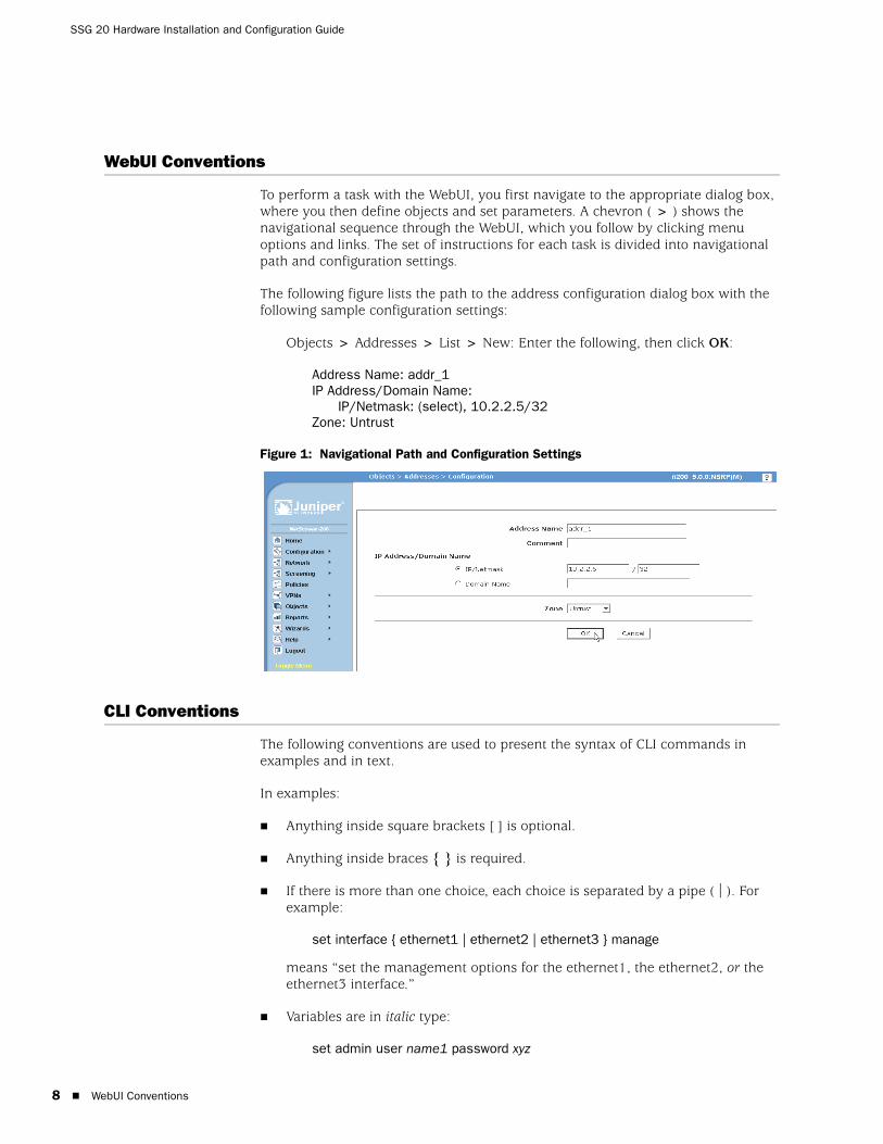
To perform a task with the WebUI, you first navigate to the appropriate dialog box, where you then define objects and set parameters. A chevron ( > ) shows the navigational sequence through the WebUI, which you follow by clicking menu options and links. The set of instructions for each task is divided into navigational path and configuration settings.
The following figure lists the path to the address configuration dialog box with the following sample configuration settings:
Objects > Addresses > List > New: Enter the following, then click OK:
Address Name: addr_1IP Address/Domain Name:
IP/Netmask: (select), 10.2.2.5/32Zone: Untrust
Figure 1: Navigational Path and Configuration Settings
CLI Conventions
The following conventions are used to present the syntax of CLI commands in examples and in text.
In examples:
Anything inside square brackets [ ] is optional.
Anything inside braces { } is required.
If there is more than one choice, each choice is separated by a pipe ( | ). For example:
set interface { ethernet1 | ethernet2 | ethernet3 } manage
means “set the management options for the ethernet1, the ethernet2, or the ethernet3 interface.”
Variables are in italic type:
set admin user name1 password xyz
WebUI Conventions
About This Guide
In text:
Commands are in boldface type.
Variables are in italic type.
Obtaining Documentation and Technical Support
To obtain technical documentation for any Juniper Networks product, visit www.juniper.net/techpubs/.
For technical support, open a support case using the Case Manager link at http://www.juniper.net/support/ or call 1-888-314-JTAC (within the United States) or 1-408-745-9500 (outside the United States).
If you find any errors or omissions in this document, please contact us at the following email address:
NOTE: When entering a keyword, you need to type only enough letters to identify the word uniquely. For example, typing set adm u kath j12fmt54 is enough to enter the command set admin user kathleen j12fmt54. Although you can use this shortcut when entering commands, all the commands documented here are presented in their entirety.
Obtaining Documentation and Technical Support 9

SSG 20 Hardware Installation and Configuration Guide
10
Obtaining Documentation and Technical Support
Chapter 1
Hardware Overview
This chapter provides detailed descriptions of the SSG 20 chassis and its components. It contains the following sections:
“Port and Power Connectors” on page 12
“Front Panel” on page 13
“Back Panel” on page 18
11
SSG 20 Hardware Installation and Configuration Guide
12
Port and Power Connectors
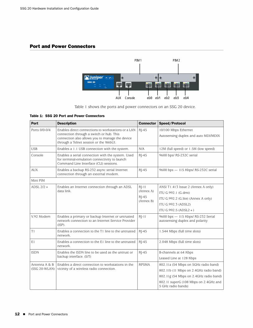
Table 1 shows the ports and power connectors on an SSG 20 device.
Table 1: SSG 20 Port and Power Connectors
AUX 0/0 10 /100AUX 0/0 10/100 0 /0 10/100 0/0 10 /100 0/0 10 /100
LINK
STATUS
POWER
PIM 2
PIM 1
b/g
802.11a
WLAN
SSG 20
1 2
PIM 2PIM 1
AUX Console e0/0 e0/1 e0/2 e0/3 e0/4
Port Description Connector Speed/Protocol
Ports 0/0-0/4 Enables direct connections to workstations or a LAN connection through a switch or hub. This connection also allows you to manage the device through a Telnet session or the WebUI.
RJ-45 10/100 Mbps Ethernet
Autosensing duplex and auto MDI/MDIX
USB Enables a 1.1 USB connection with the system. N/A 12M (full speed) or 1.5M (low speed)
Console Enables a serial connection with the system. Used for terminal-emulation connectivity to launch Command Line Interface (CLI) sessions.
RJ-45 9600 bps/ RS-232C serial
AUX Enables a backup RS-232 async serial Internet connection through an external modem.
RJ-45 9600 bps — 115 Kbps/ RS-232C serial
Mini PIM
ADSL 2/2+ Enables an Internet connection through an ADSL data link.
RJ-11 (Annex A)
RJ-45 (Annex B)
ANSI T1.413 Issue 2 (Annex A only)
ITU G.992.1 (G.dmt)
ITU G.992.2 (G.lite) (Annex A only)
ITU G.992.3 (ADSL2)
ITU G.992.5 (ADSL2+)
V.92 Modem Enables a primary or backup Internet or untrusted network connection to an Internet Service Provider (ISP).
RJ-11 9600 bps — 115 Kbps/ RS-232 Serial autosensing duplex and polarity
T1 Enables a connection to the T1 line to the untrusted network.
RJ-45 1.544 Mbps (full time slots)
E1 Enables a connection to the E1 line to the untrusted network.
RJ-45 2.048 Mbps (full time slots)
ISDN Enables the ISDN line to be used as the untrust or backup interface. (S/T)
RJ-45 B-channels at 64 Kbps
Leased Line at 128 Kbps
Antenna A & B (SSG 20-WLAN)
Enables a direct connection to workstations in the vicinity of a wireless radio connection.
RPSMA 802.11a (54 Mbps on 5GHz radio band)
802.11b (11 Mbps on 2.4GHz radio band)
802.11g (54 Mbps on 2.4GHz radio band)
802.11 superG (108 Mbps on 2.4GHz and 5 GHz radio bands)
Port and Power Connectors
Front Panel
This section describes the following elements on the front panel of an SSG 20 device:
System Status LEDs
Port Descriptions
Mini Physical Interface Module Port Descriptions
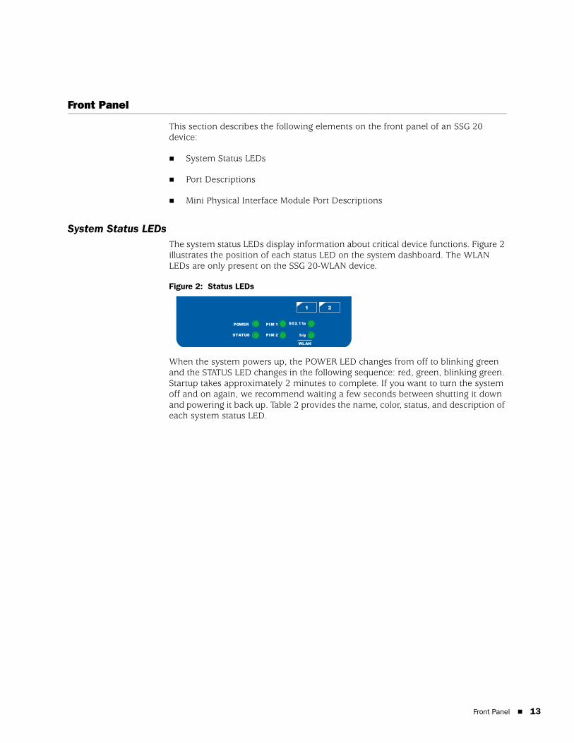
System Status LEDsThe system status LEDs display information about critical device functions. Figure 2 illustrates the position of each status LED on the system dashboard. The WLAN LEDs are only present on the SSG 20-WLAN device.
Figure 2: Status LEDs
When the system powers up, the POWER LED changes from off to blinking green and the STATUS LED changes in the following sequence: red, green, blinking green. Startup takes approximately 2 minutes to complete. If you want to turn the system off and on again, we recommend waiting a few seconds between shutting it down and powering it back up. Table 2 provides the name, color, status, and description of each system status LED.
STATUS
POWER
PIM 2
PIM 1
b/g
802. 11a
WLAN
1 2
Front Panel 13
SSG 20 Hardware Installation and Configuration Guide
14
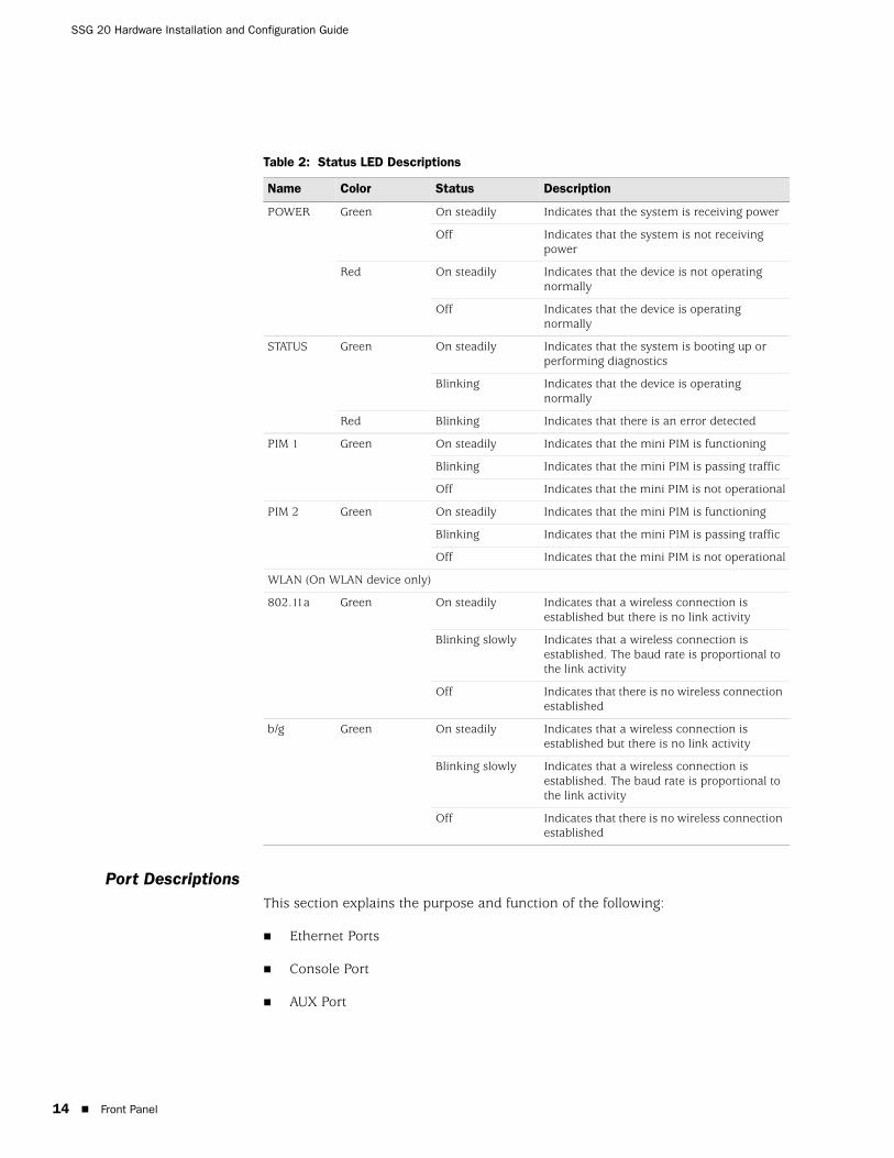
Table 2: Status LED Descriptions
Port DescriptionsThis section explains the purpose and function of the following:
Ethernet Ports
Console Port
AUX Port
Name Color Status Description
POWER Green On steadily Indicates that the system is receiving power
Off Indicates that the system is not receiving power
Red On steadily Indicates that the device is not operating normally
Off Indicates that the device is operating normally
STATUS Green On steadily Indicates that the system is booting up or performing diagnostics
Blinking Indicates that the device is operating normally
Red Blinking Indicates that there is an error detected
PIM 1 Green On steadily Indicates that the mini PIM is functioning
Blinking Indicates that the mini PIM is passing traffic
Off Indicates that the mini PIM is not operational
PIM 2 Green On steadily Indicates that the mini PIM is functioning
Blinking Indicates that the mini PIM is passing traffic
Off Indicates that the mini PIM is not operational
WLAN (On WLAN device only)
802.11a Green On steadily Indicates that a wireless connection is established but there is no link activity
Blinking slowly Indicates that a wireless connection is established. The baud rate is proportional to the link activity
Off Indicates that there is no wireless connection established
b/g Green On steadily Indicates that a wireless connection is established but there is no link activity
Blinking slowly Indicates that a wireless connection is established. The baud rate is proportional to the link activity
Off Indicates that there is no wireless connection established
Front Panel
Ethernet PortsFive 10/100 Ethernet ports provide LAN connections to hubs, switches, local servers, and workstations. You can also designate an Ethernet port for management traffic. The ports are labeled 0/0 through 0/4. For the default zone bindings for each Ethernet port, see “Default Device Settings” on page 31.
When configuring one of the ports, reference the interface name that corresponds to the location of the port. From left to right on the front panel, the interface names for the ports are named ethernet0/0 through ethernet0/4.
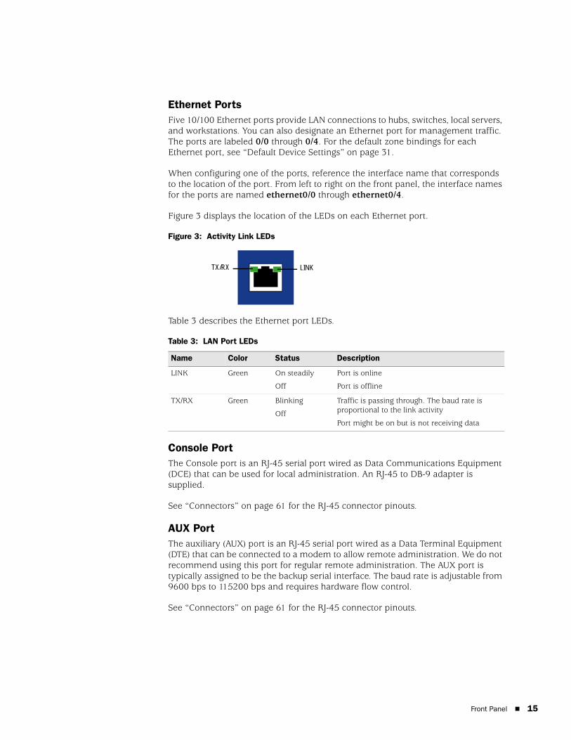
Figure 3 displays the location of the LEDs on each Ethernet port.
Figure 3: Activity Link LEDs
Table 3 describes the Ethernet port LEDs.
Table 3: LAN Port LEDs
Console PortThe Console port is an RJ-45 serial port wired as Data Communications Equipment (DCE) that can be used for local administration. An RJ-45 to DB-9 adapter is supplied.
See “Connectors” on page 61 for the RJ-45 connector pinouts.
AUX PortThe auxiliary (AUX) port is an RJ-45 serial port wired as a Data Terminal Equipment (DTE) that can be connected to a modem to allow remote administration. We do not recommend using this port for regular remote administration. The AUX port is typically assigned to be the backup serial interface. The baud rate is adjustable from 9600 bps to 115200 bps and requires hardware flow control.
See “Connectors” on page 61 for the RJ-45 connector pinouts.
Name Color Status Description
LINK Green On steadily
Off
Port is online
Port is offline
TX/RX Green Blinking
Off
Traffic is passing through. The baud rate is proportional to the link activity
Port might be on but is not receiving data
LINKTX/RX
Front Panel 15
SSG 20 Hardware Installation and Configuration Guide
16
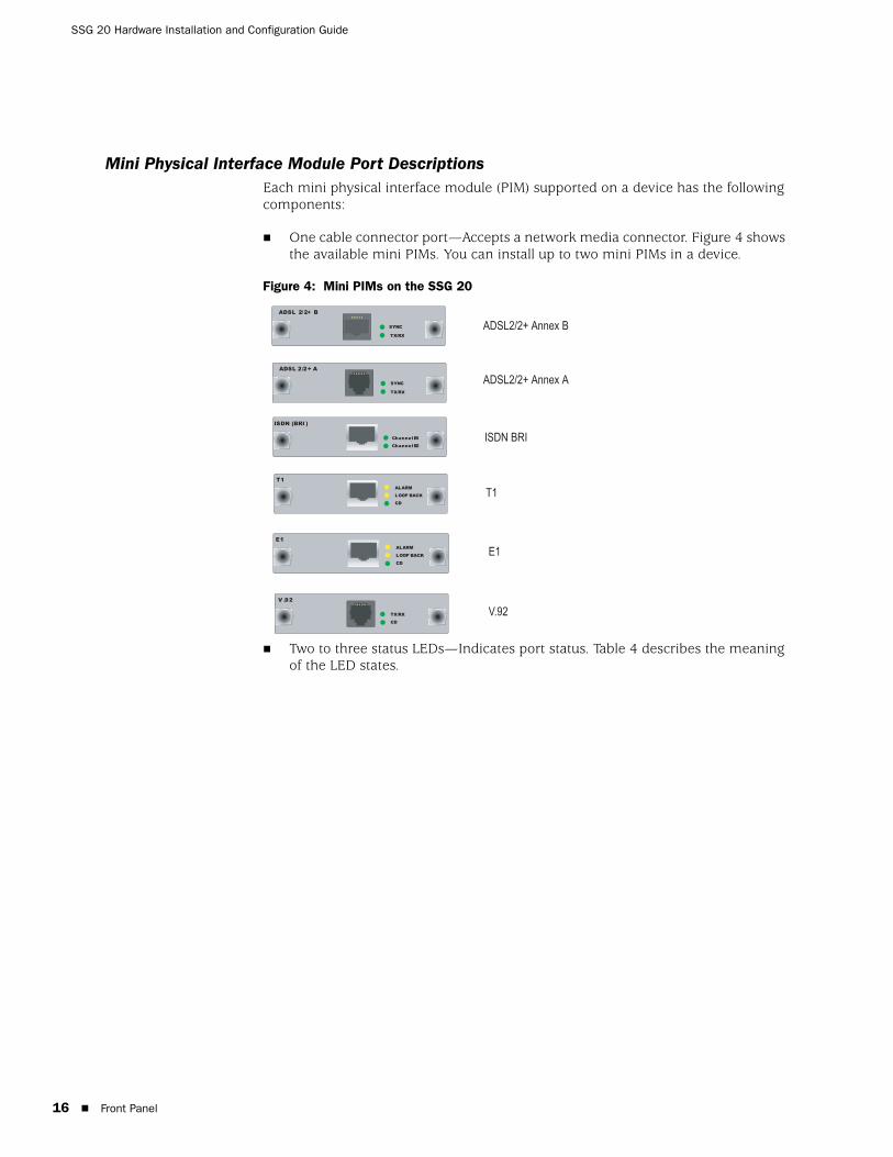
Mini Physical Interface Module Port DescriptionsEach mini physical interface module (PIM) supported on a device has the following components:
One cable connector port—Accepts a network media connector. Figure 4 shows the available mini PIMs. You can install up to two mini PIMs in a device.
Figure 4: Mini PIMs on the SSG 20
Two to three status LEDs—Indicates port status. Table 4 describes the meaning of the LED states.
ISDN BRI
T1
V.92
E1
ADSL2/2+ Annex A
ADSL2/2+ Annex B
ISDN (BRI )
Channel B2
Channel B1
V .92
CD
TX/RX
ADSL 2 /2+ A
TX/RX
SYNC
T1
CD
LOOP BACK
ALARM
E1
CD
LOOP BACK
ALARM
TX/RX
SYNC
ADSL 2/2+ B
Front Panel

Table 4: Mini PIM LED States on the SSG 20
Type Name Color State Description
ADSL 2/2+
(Annex A and B)
SYNC Green On steadily Indicates that the ADSL interface is trained
Blinking Indicates training is in progress
Off Interface is idle
TX/RX Green Blinking Indicates that traffic is passing through
Off Indicates that no traffic is passing through
ISDN (BRI) CH B1 Green On steadily Indicates that B-Channel 1 is active
Off Indicates that B-Channel 1 is not active
CH B2 Green On steadily Indicates that B-Channel 2 is active
Off Indicates that B-Channel 2 is not active
T1/E1 ALARM Yellow On steadily Indicates that there is a local or remote alarm; device has detected a failure
Off Indicates that there are no alarms or failures
LOOP BACK Yellow On steadily Indicates that a loopback or line state is detected
Off Indicates that the loopback is not active
CD Green On steadily Indicates a carrier was detected and the internal DSU/CSU in the mini PIM is communicating with another DSU/CSU
Off Indicates that carrier detect is not active
V.92 CD Green On steadily Indicates that the link is active
Off Indicates that the serial interface is not in service
TX/RX Green Blinking Indicates that traffic is passing through
Off Indicates that no traffic is passing through
CAUTION: Mini PIMs are not hot-swappable. You must install them in the front panel slots before powering on the device.
Front Panel 17

SSG 20 Hardware Installation and Configuration Guide
18
Back Panel
This section describes the following elements on the back panel of an SSG 20 device:
Power Adapter
Radio Transceivers
Grounding Lug
Antennae Types
Universal Serial Bus Host Module
Figure 5: Back Panel of an SSG 20-WLAN Device
Power AdapterThe POWER LED on the front panel of a device either glows green or is off. Green indicates correct function and off indicates power adapter failure.
Radio TransceiversThe SSG 20-WLAN contains two wireless connectivity radio transceivers, which support 802.11a/b/g standards. The first transceiver (WLAN 0), uses the 2.4 GHz radio band, which supports the 802.11b standard at 11 Mbps, the 802.11g standard at 54 Mbps, and 802.11 SuperG standard at 108 Mbps. The second radio transceiver (WLAN 1), uses the 5 GHz radio band, which supports the 802.11a standard at 54 Mbps. For information on configuring the wireless radio band, see “Wireless Network Configuration” on page 38.
Grounding LugA one-hole grounding lug is provided on the back of the chassis to connect the device to earth ground.
To ground the device before connecting power, connect a grounding cable to earth ground and then attach the cable to the lug on the rear of the chassis.
B A
LOCK
DC POWER12V A4
RESETUSB
power adapter
USB host module
grounding lug
Antenna B Antenna A
reset pinhole
device security lock
Back Panel

Antennae TypesThe SSG 20-WLAN device supports three types of custom-built radio antennae:
Diversity antennae — The diversity antennae provide 2dBi directional coverage and a fairly uniform level of signal strength within the area of coverage and are suitable for most installations. This type of antennae is shipped with the device.
External omnidirectional antenna — The external antenna provides 2dBi omnidirectional coverage. Unlike diversity antennae, which function as a pair, an external antenna operates to eliminate an echo effect that can sometimes occur from slightly delayed characteristics in signal reception when two are in use.
External directional antenna — The external directional antenna provides 2dBi unidirectional coverage and is well suited for such places as hallways and outer walls (with the antenna facing inward).
Universal Serial Bus Host ModuleThe slot labeled USB on the back panel of an SSG 20 device implements a host-only universal serial bus (USB) 1.1 host module for a USB device adapter or USB flash key, as defined in the CompactFlash Specification published by the CompactFlash Association. When the USB storage device is installed and configured, it automatically acts as a secondary storage device.
The USB host module allows file transfers, such as device configurations, user certifications, and update version images between an external USB flash key and the internal flash storage located in the security device. The USB host module supports USB 1.1 specification at either low-speed (1.5M) or full-speed (12M) file transfer.
To use a USB flash key to transfer files between the device, do the following:
1. Insert the USB flash key into the USB host module on the security device.
2. Save the files from the USB flash key to the internal flash storage on the device with the save { software | config | image-key } from usb filename to flash CLI command.
3. Before removing the USB flash key, stop the host module with the exec usb-device stop CLI command.
4. It is now safe to remove the USB flash key.
If you want to delete a file from the USB flash key, use the delete file usb:/filename CLI command.
If you want to view the saved file information on the USB flash key or internal flash storage, use the get file CLI command.
Back Panel 19

SSG 20 Hardware Installation and Configuration Guide
20
Back Panel
Chapter 2
Installing and Connecting the Device
This chapter describes how to mount an SSG 20 device and connect cables and power to the device. Topics in this chapter include:
“Before You Begin” on this page
“Equipment Installation” on page 22
“Connecting the Interface Cable to a Device” on page 23
“Connecting the Power” on page 23
“Connecting the Device to a Network” on page 23
Before You Begin
The location of the chassis, the layout of the mounting equipment, and the security of your wiring room are crucial for proper system operation.
Observing the following precautions can prevent shutdowns, equipment failures, and injuries:
Before installation, always check that the power supply is disconnected from any power source.
Ensure that the room in which you operate the device has adequate air circulation and that the room temperature does not exceed 104 °F (40 °C).
NOTE: For safety warnings and instructions, please refer to the Juniper Networks Security Products Safety Guide. Before working on any equipment, you should be aware of the hazards involved with electrical circuitry and be familiar with standard practices for preventing accidents.
WARNING: To prevent abuse and intrusion by unauthorized personnel, install an SSG 20 device in a secure environment.
Before You Begin 21
SSG 20 Hardware Installation and Configuration Guide
22
Do not place the device in an equipment rack frame that blocks an intake or exhaust port. Ensure that enclosed racks have fans and louvered sides.
Correct these hazardous conditions before any installation: moist or wet floors, leaks, ungrounded or frayed power cables, or missing safety grounds.
Equipment Installation
You can front-mount, wall-mount, or desk-mount an SSG 20 device. The mounting kits may be purchased separately.
To mount an SSG 20 device, you need a number 2 phillips screwdriver (not provided) and screws that are compatible with the equipment rack (included in the kit).
To front-mount an SSG 20 device onto a standard 19-inch equipment rack, do the following:
1. Align the rack mount ears to the device.
2. Place the screws in the holes and use a phillips screwdriver to secure them.
3. Mount the device on the rack with the provided screws.
4. Plug the power supply into the power outlet.
To wall-mount an SSG 20 device, do the following:
1. Align the wall mount ears to the device.
2. Place the screws in the holes and use a phillips screwdriver to secure them.
3. Ensure that the wall to be used is smooth, flat, dry and sturdy.
4. Mount the device on the wall with the provided screws.
5. Plug the power supply into the power outlet.
To desk-mount an SSG 20 device, do the following:
1. Attach the desktop stand to the side of the device. We recommend the side closest to the power adapter.
2. Place the mounted device on the desktop.
3. Plug the power supply into the power outlet.
NOTE: When mounting a device, make sure that it is within reach of the power outlet.
Equipment Installation
Connecting the Interface Cable to a Device
To connect the interface cable to a device, do the following:
1. Have ready a length of the type of cable used by the interface.
2. Insert the cable connector into the cable-connector port on the interface faceplate.
3. Arrange the cable as follows to prevent it from dislodging or developing stress points:
a. Secure the cable so that it is not supporting its own weight as it hangs to the floor.
b. Place any excess cable out of the way in a neatly coiled loop.
c. Use fasteners to maintain the shape of the cable loops.
Connecting the Power
To connect the power to a device, do the following:
1. Plug the DC connector end of the power cable into the DC power receptacle on the back of the device.
2. Plug the AC adapter end of the power cable into an AC power source.
Connecting the Device to a Network
An SSG 20 device provides firewall and general security for networks when it is placed between internal networks and the untrusted network. This section describes the following:
Connecting an SSG 20 Device to an Untrusted Network
Connecting the Device to an Internal Network or a Workstation
WARNING: We recommend using a surge protector for the power connection.
Connecting the Interface Cable to a Device 23
SSG 20 Hardware Installation and Configuration Guide
24
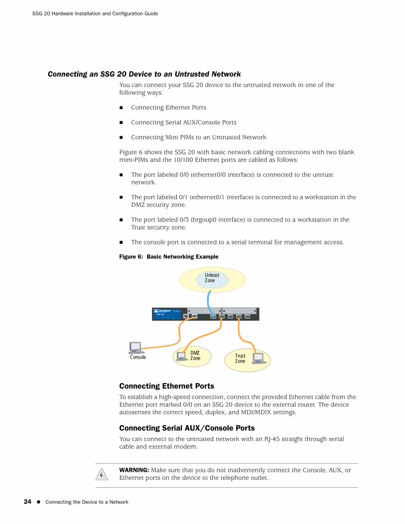
Connecting an SSG 20 Device to an Untrusted NetworkYou can connect your SSG 20 device to the untrusted network in one of the following ways:
Connecting Ethernet Ports
Connecting Serial AUX/Console Ports
Connecting Mini PIMs to an Untrusted Network
Figure 6 shows the SSG 20 with basic network cabling connections with two blank mini-PIMs and the 10/100 Ethernet ports are cabled as follows:
The port labeled 0/0 (ethernet0/0 interface) is connected to the untrust network.
The port labeled 0/1 (ethernet0/1 interface) is connected to a workstation in the DMZ security zone.
The port labeled 0/3 (brgoup0 interface) is connected to a workstation in the Trust security zone.
The console port is connected to a serial terminal for management access.
Figure 6: Basic Networking Example
Connecting Ethernet PortsTo establish a high-speed connection, connect the provided Ethernet cable from the Ethernet port marked 0/0 on an SSG 20 device to the external router. The device autosenses the correct speed, duplex, and MDI/MDIX settings.
Connecting Serial AUX/Console PortsYou can connect to the untrusted network with an RJ-45 straight through serial cable and external modem.
AUX 0/0 10 /100AUX 0/0 10/100 0 /0 10/100 0/0 10 /100 0/0 10 /100
LINK
STATUS
POWER
PIM 2
PIM 1
b/g
802.11a
WLAN
SSG 20
1 2
Untrust Zone
Trust Zone
DMZ ZoneConsole
WARNING: Make sure that you do not inadvertently connect the Console, AUX, or Ethernet ports on the device to the telephone outlet.
Connecting the Device to a Network

Connecting Mini PIMs to an Untrusted NetworkThis section explains how to connect the device mini PIMs to an untrusted network.
ADSL2/2+ Mini PIMConnect the provided ADSL cable from the ADSL2/2+ mini PIM to your telephone outlet. The ADSL port on the Annex A version of the device uses an RJ-11 connector, while the Annex B version uses an RJ-45 connector. In the case of Annex B models, the cable you connect from the ADSL port to the telephone outlet is identical in appearance and wiring to a straight through 10 Base-T Ethernet cable.
Connecting Splitters and Microfilters
A signal splitter divides the telephone signal into low-frequency voice signals for voice calls and high-frequency data signals for data traffic. Your service provider usually installs the splitter as part of the equipment that connects your site telephone lines to the provider network.
There are also splitters that you may be able to install yourself, depending upon your service-provider equipment. If you are installing such a splitter yourself, connect the ADSL cable from the device and the telephone line to the appropriate connectors (for example, “data” or “voice”) on the splitter. You connect the other end of the splitter to the telephone outlet.
You may need to install a microfilter on each telephone, fax machine, answering machine, or analog modem that connects to the ADSL line. The microfilter filters out high-frequency noise on the telephone line. You install the microfilter on the telephone line between the telephone, fax machine, answering machine, or analog modem and the voice connector on the splitter.
Figure 7 shows an example of a microfilter and a splitter that you install on your site. (You must obtain the appropriate microfilters or splitters from your service provider.)
Figure 7: Microfilter and Splitter on Your Network Connection
CONSOLEAUX
SSG 20TX/RX LINK
TX/RX
SYNC1 2
ADSL 2 /2+
0/0 10/100 0 /1 10 /100 0 /2 10 /100 0 /4 10 /100 0/5 10 /100
STATUS
POWER
PIM 2
PIM 1
b/g
802.11a
WLAN
TX RX
SYNC
ADSL 2+
DATA VOICE
Connecting the Device to a Network 25
SSG 20 Hardware Installation and Configuration Guide
26
ISDN, T1, E1, and V.92 Mini PIMsTo connect the mini PIMs to a device, do the following:
1. Have ready a length of the type of cable used by the interface.
2. Insert the cable connector into the cable-connector port on the interface faceplate.
3. Arrange the cable as follows to prevent it from dislodging or developing stress points:
a. Secure the cable so that it is not supporting its own weight as it hangs to the floor.
b. Place any excess cable out of the way in a neatly coiled loop.
c. Use fasteners to maintain the shape of the cable loops.
To configure the ISDN, E1, T1, or V.92 Mini PIM, see “Mini PIM Configuration” on page 41.
Connecting the Device to an Internal Network or a WorkstationYou can connect your local area network (LAN) or workstation with the Ethernet and/or wireless interfaces.
Connecting Ethernet PortsAn SSG 20 device contains five Ethernet ports. You can use one or more of these ports to connect to LANs through switches or hubs. You can also connect one or all of the ports directly to workstations, eliminating the need for a hub or switch. You can use either crossover or straight through cables to connect the Ethernet ports to other devices. See “Default Device Settings” on page 31 for the default zone to interface bindings.
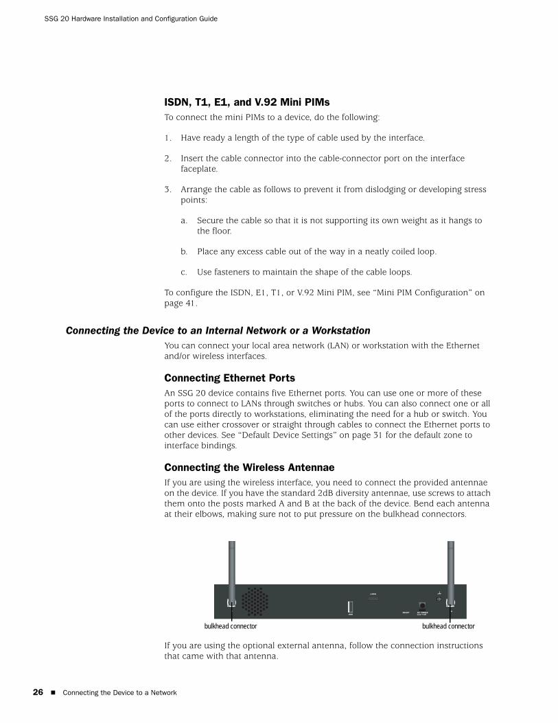
Connecting the Wireless AntennaeIf you are using the wireless interface, you need to connect the provided antennae on the device. If you have the standard 2dB diversity antennae, use screws to attach them onto the posts marked A and B at the back of the device. Bend each antenna at their elbows, making sure not to put pressure on the bulkhead connectors.
If you are using the optional external antenna, follow the connection instructions that came with that antenna.
B A
LOCK
DC POWER12V A4
RESETUSB
bulkhead connectorbulkhead connector
Connecting the Device to a Network
Chapter 3
Configuring the Device
ScreenOS software is preinstalled on an SSG 20 device. When the device is powered on, it is ready to be configured. While the device has a default factory configuration that allows you to initially connect to the device, you need to perform further configuration for your specific network requirements.
This chapter contains the following sections:
“Access the Device” on page 28
“Default Device Settings” on page 31
“Basic Device Configuration” on page 33
“Wireless Configuration” on page 37
“Mini PIM Configuration” on page 41
“Basic Firewall Protections” on page 49
“Verifying External Connectivity” on page 49
“Resetting the Device to Factory Defaults” on page 50
NOTE: After you configure a device and verify connectivity through the remote network, you must register your product at www.juniper.net/support/ so certain ScreenOS services, such as Deep Inspection Signature Service and Anti-Virus (purchased separately), can be activated on the device. After registering your product, use the WebUI to obtain the subscription for the service. For more information about registering your product and obtaining subscriptions for specific services, refer to the Fundamentals volume of the Concepts & Examples ScreenOS Reference Guide for the ScreenOS version running on the device.
27

SSG 20 Hardware Installation and Configuration Guide
28
Access the Device
You can configure and manage a device in several ways:
Console: The Console port on the device allows you to access the device through a serial cable connected to your workstation or terminal. To configure the device, you enter ScreenOS Command Line Interface (CLI) commands on your terminal or in a terminal-emulation program on your workstation.
WebUI: The ScreenOS WebUI is a graphical interface available through a Web browser. To initially use the WebUI, the workstation on which you run the Web browser must be on the same subnetwork as the device. You can also access the WebUI through a secure server using secure sockets layer (SSL) using secure HTTP (S-HTTP).
Telnet/SSH: Telnet and Secure Shell (SSH) are applications that allows you to access devices through an IP network. To configure the device, you enter ScreenOS CLI commands in a Telnet session from your workstation. For more information, see the Administration volume of the Concepts & Examples ScreenOS Reference Guide.
NetScreen-Security Manager: NetScreen-Security Manager is a Juniper Networks enterprise-level management application that enables you to control and manage Juniper Networks firewall/IPSec VPN devices. For instructions on how to manage your device with NetScreen-Security Manager, refer to the NetScreen-Security Manager Administrator’s Guide.
Using a Console Connection
To establish a console connection, do the following:
1. Plug the female end of the supplied DB-9 adapter into the serial port of your workstation. (Be sure that the DB-9 is inserted properly and secured.) Figure 8 shows the type of DB-9 connector that is needed.
Figure 8: DB-9 Adapter
2. Plug the male end of the RJ-45 CAT5 serial cable into the Console port on the SSG 20. (Be sure that the other end of the CAT5 cable is inserted properly and secured in the DB-9 adapter.)
NOTE: Use a straight through RJ-45 CAT5 serial cable with a male RJ-45 connector to plug into the Console port on the devices.
RJ-45 Jack
DB-9 adapter
RJ-45 cable
Access the Device

3. Launch a serial terminal-emulation program on your workstation. The required settings to launch a console session with the devices are as follows:
Baud rate: 9600
Parity: None
Data bits: 8
Stop bit: 1
Flow Control: None
4. If you have not yet changed the default login for the admin name and password, enter netscreen in both the login and password prompts. (Use lowercase letters only. The login and password fields are both case-sensitive.)
For information on how to configure the device with the CLI commands, see the Concepts & Examples ScreenOS Reference Guide.
5. (Optional) By default, the console times out and terminates automatically after 10 minutes of idle time. To remove the timeout, enter set console timeout 0.
Using the WebUITo use the WebUI, the workstation from which you are managing the device must initially be on the same subnetwork as the device. To access the device with the WebUI, do the following:
1. Connect your workstation to the 0/2 — 0/4 port (bgroup0 interface in the Trust zone) on the device.
2. Ensure that your workstation is configured for DHCP or is statically configured with an IP address in the 192.168.1.0/24 subnet.
3. Launch your browser, enter the IP address for the bgroup0 interface (the default IP address is 192.168.1.1/24), then press Enter.
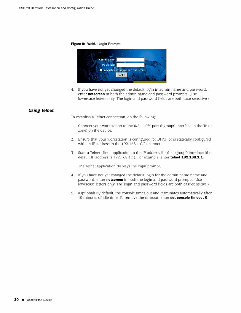
The WebUI application displays the login prompt as shown in Figure 9.
NOTE: When the device is accessed through the WebUI the first time, the Initial Configuration Wizard appears. If you decide to use the Initial Configuration Wizard to configure your device, see “Initial Configuration Wizard” on page 65.
Access the Device 29
SSG 20 Hardware Installation and Configuration Guide
30
Figure 9: WebUI Login Prompt
4. If you have not yet changed the default login in admin name and password, enter netscreen in both the admin name and password prompts. (Use lowercase letters only. The login and password fields are both case-sensitive.)
Using TelnetTo establish a Telnet connection, do the following:
1. Connect your workstation to the 0/2 — 0/4 port (bgroup0 interface in the Trust zone) on the device.
2. Ensure that your workstation is configured for DHCP or is statically configured with an IP address in the 192.168.1.0/24 subnet.
3. Start a Telnet client application to the IP address for the bgroup0 interface (the default IP address is 192.168.1.1). For example, enter telnet 192.168.1.1.
The Telnet application displays the login prompt.
4. If you have not yet changed the default login for the admin name name and password, enter netscreen in both the login and password prompts. (Use lowercase letters only. The login and password fields are both case-sensitive.)
5. (Optional) By default, the console times out and terminates automatically after 10 minutes of idle time. To remove the timeout, enter set console timeout 0.
Access the Device
Default Device Settings
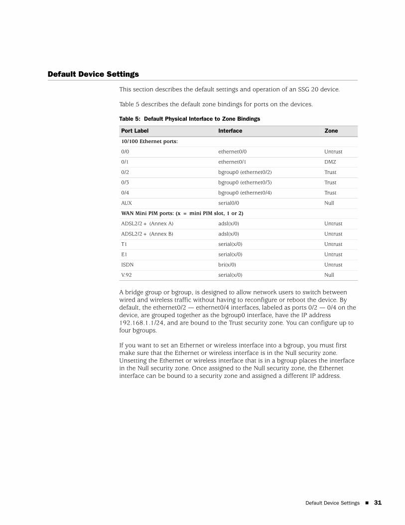
This section describes the default settings and operation of an SSG 20 device.
Table 5 describes the default zone bindings for ports on the devices.
Table 5: Default Physical Interface to Zone Bindings
A bridge group or bgroup, is designed to allow network users to switch between wired and wireless traffic without having to reconfigure or reboot the device. By default, the ethernet0/2 — ethernet0/4 interfaces, labeled as ports 0/2 — 0/4 on the device, are grouped together as the bgroup0 interface, have the IP address 192.168.1.1/24, and are bound to the Trust security zone. You can configure up to four bgroups.
If you want to set an Ethernet or wireless interface into a bgroup, you must first make sure that the Ethernet or wireless interface is in the Null security zone. Unsetting the Ethernet or wireless interface that is in a bgroup places the interface in the Null security zone. Once assigned to the Null security zone, the Ethernet interface can be bound to a security zone and assigned a different IP address.
Port Label Interface Zone
10/100 Ethernet ports:
0/0 ethernet0/0 Untrust
0/1 ethernet0/1 DMZ
0/2 bgroup0 (ethernet0/2) Trust
0/3 bgroup0 (ethernet0/3) Trust
0/4 bgroup0 (ethernet0/4) Trust
AUX serial0/0 Null
WAN Mini PIM ports: (x = mini PIM slot, 1 or 2)
ADSL2/2+ (Annex A) adsl(x/0) Untrust
ADSL2/2+ (Annex B) adsl(x/0) Untrust
T1 serial(x/0) Untrust
E1 serial(x/0) Untrust
ISDN bri(x/0) Untrust
V.92 serial(x/0) Null
Default Device Settings 31
SSG 20 Hardware Installation and Configuration Guide
32
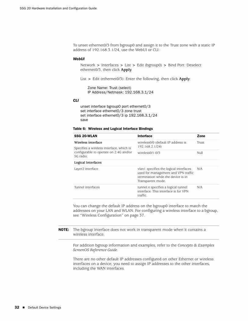
To unset ethernet0/3 from bgroup0 and assign it to the Trust zone with a static IP address of 192.168.3.1/24, use the WebUI or CLI:
WebUI
Network > Interfaces > List > Edit (bgroup0) > Bind Port: Deselect ethernet0/3, then click Apply.
List > Edit (ethernet0/3): Enter the following, then click Apply:
Zone Name: Trust (select)IP Address/Netmask: 192.168.3.1/24
CLI
unset interface bgroup0 port ethernet0/3set interface ethernet0/3 zone trustset interface ethernet0/3 ip 192.168.3.1/24save
Table 6: Wireless and Logical Interface Bindings
You can change the default IP address on the bgroup0 interface to match the addresses on your LAN and WLAN. For configuring a wireless interface to a bgroup, see “Wireless Configuration” on page 37.
For addition bgroup information and examples, refer to the Concepts & Examples ScreenOS Reference Guide.
There are no other default IP addresses configured on other Ethernet or wireless interfaces on a device; you need to assign IP addresses to the other interfaces, including the WAN interfaces.
SSG 20-WLAN Interface Zone
Wireless interface
Specifies a wireless interface, which is configurable to operate on 2.4G and/or 5G radio.
wireless0/0 (default IP address is 192.168.2.1/24)
Trust
wireless0/1-0/3 Null
Logical Interfaces
Layer2 interface vlan1 specifies the logical interfaces used for management and VPN traffic termination while the device is in Transparent mode.
N/A
Tunnel interfaces tunnel.n specifies a logical tunnel interface. This interface is for VPN traffic.
N/A
NOTE: The bgroup interface does not work in transparent mode when it contains a wireless interface.
Default Device Settings
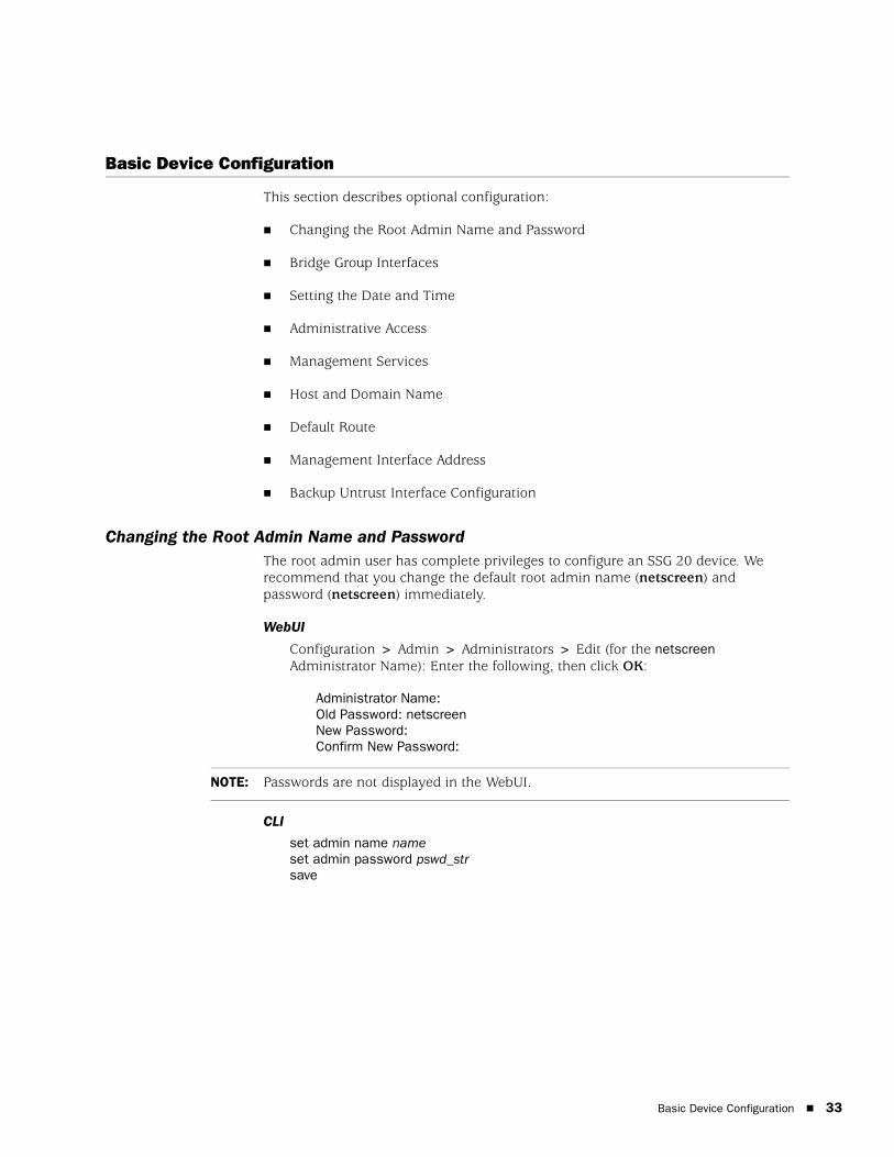
Basic Device Configuration
This section describes optional configuration:
Changing the Root Admin Name and Password
Bridge Group Interfaces
Setting the Date and Time
Administrative Access
Management Services
Host and Domain Name
Default Route
Management Interface Address
Backup Untrust Interface Configuration
Changing the Root Admin Name and PasswordThe root admin user has complete privileges to configure an SSG 20 device. We recommend that you change the default root admin name (netscreen) and password (netscreen) immediately.
WebUI
Configuration > Admin > Administrators > Edit (for the netscreen Administrator Name): Enter the following, then click OK:
Administrator Name:Old Password: netscreenNew Password:Confirm New Password:
CLI
set admin name nameset admin password pswd_strsave
NOTE: Passwords are not displayed in the WebUI.
Basic Device Configuration 33
SSG 20 Hardware Installation and Configuration Guide
34
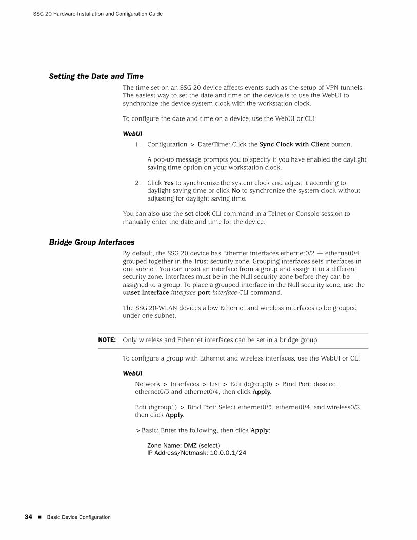
Setting the Date and TimeThe time set on an SSG 20 device affects events such as the setup of VPN tunnels. The easiest way to set the date and time on the device is to use the WebUI to synchronize the device system clock with the workstation clock.
To configure the date and time on a device, use the WebUI or CLI:
WebUI
1. Configuration > Date/Time: Click the Sync Clock with Client button.
A pop-up message prompts you to specify if you have enabled the daylight saving time option on your workstation clock.
2. Click Yes to synchronize the system clock and adjust it according to daylight saving time or click No to synchronize the system clock without adjusting for daylight saving time.
You can also use the set clock CLI command in a Telnet or Console session to manually enter the date and time for the device.
Bridge Group InterfacesBy default, the SSG 20 device has Ethernet interfaces ethernet0/2 — ethernet0/4 grouped together in the Trust security zone. Grouping interfaces sets interfaces in one subnet. You can unset an interface from a group and assign it to a different security zone. Interfaces must be in the Null security zone before they can be assigned to a group. To place a grouped interface in the Null security zone, use the unset interface interface port interface CLI command.
The SSG 20-WLAN devices allow Ethernet and wireless interfaces to be grouped under one subnet.
To configure a group with Ethernet and wireless interfaces, use the WebUI or CLI:
WebUI
Network > Interfaces > List > Edit (bgroup0) > Bind Port: deselect ethernet0/3 and ethernet0/4, then click Apply.
Edit (bgroup1) > Bind Port: Select ethernet0/3, ethernet0/4, and wireless0/2, then click Apply.
>Basic: Enter the following, then click Apply:
Zone Name: DMZ (select)IP Address/Netmask: 10.0.0.1/24
NOTE: Only wireless and Ethernet interfaces can be set in a bridge group.
Basic Device Configuration
CLI
unset interface bgroup0 port ethernet0/3unset interface bgroup0 port ethernet0/4set interface bgroup1 port ethernet0/3set interface bgroup1 port ethernet0/4set interface bgroup1 port wireless0/2set interface bgroup1 zone DMZset interface bgroup1 ip 10.0.0.1/24save
Administrative AccessBy default, anyone in your network can manage a device if they know the login and password. To configure the device to be managed only from a specific host on your network, use the WebUI or CLI:
WebUI
Configuration > Admin > Permitted IPs: Enter the following, then click Add:
IP Address/Netmask: ip_addr/mask
CLI
set admin manager-ip ip_addr/masksave
Management ServicesScreenOS provides services for configuring and managing the device, such as SNMP, SSL, and SSH, which you can enable on a per-interface basis. To configure the management services on the device, use the WebUI or CLI:
WebUI
Network > Interfaces > List > Edit (for ethernet0/0): Under Management Services, select or clear the management services you want to use on the interface, then click Apply.
CLI
set interface ethernet0/0 manage webunset interface ethernet0/0 manage snmpsave
Basic Device Configuration 35

SSG 20 Hardware Installation and Configuration Guide
36
Host and Domain NameThe domain name defines the network or subnetwork that the device belongs to, while the hostname refers to a specific device. The hostname and domain name together uniquely identify the device in the network. To configure the host and domain name on a device, use the WebUI or CLI:
WebUI
Network > DNS > Host: Enter the following, then click Apply:
Host Name: nameDomain Name: name
CLI
set hostname nameset domain namesave
Default RouteThe default route is a static route used to direct packets addressed to networks that are not explicitly listed in the routing table. If a packet arrives at the device with an address that the device does not have routing information for, the device sends the packet to the destination specified by the default route. To configure the default route on the device, use the WebUI or CLI:
WebUI
Network > Routing > Destination > New (trust-vr): Enter the following, then click OK:
IP Address/Netmask: 0.0.0.0/0.0.0.0Next Hop
Gateway: (select)Interface: ethernet0/2 (select)Gateway IP Address: ip_addr
CLIset route 0.0.0.0/0 interface ethernet0/2 gateway ip_addrsave
Management Interface AddressThe Trust interface has the default IP address 192.168.1.1/24 and is configured for management services. If you connect the 0/2 — 0/4 ports on the device to a workstation, you can configure the device from a workstation in the 192.168.1.1/24 subnetwork using a management service such as Telnet.
You can change the default IP address on the trust interface. For example, you might want to change the interface to match IP addresses that already exist on your LAN.
Basic Device Configuration
Backup Untrust Interface ConfigurationThe SSG 20 device allows you to configure a backup interface for untrust failover. To set a backup interface for untrust failover, do the following:
1. Set the backup interface in the Null security zone with the unset interface interface [ port interface ] CLI command.
2. Bind the backup interface to the same security zone as the primary interface with the set interface interface zone zone_name CLI command.
To set the ethernet0/4 interface as the backup interface to the ethernet0/0 interface, use the WebUI or CLI:
WebUI
Network > Interfaces > Backup > Enter the following, then click Apply.
Primary: ethernet0/0Backup: ethernet0/4Type: track-ip (select)
CLI
unset interface bgroup0 port ethernet0/4set interface ethernet0/4 zone untrustset interface ethernet0/0 backup interface ethernet0/4 type track-ipsave
Wireless Configuration
This section provides information for configuring the wireless interface on the SSG 20-WLAN device. To use the wireless local area network (WLAN) capabilities on the device, you must configure at least one Service Set Identifier (SSID) and bind it to a wireless interface.
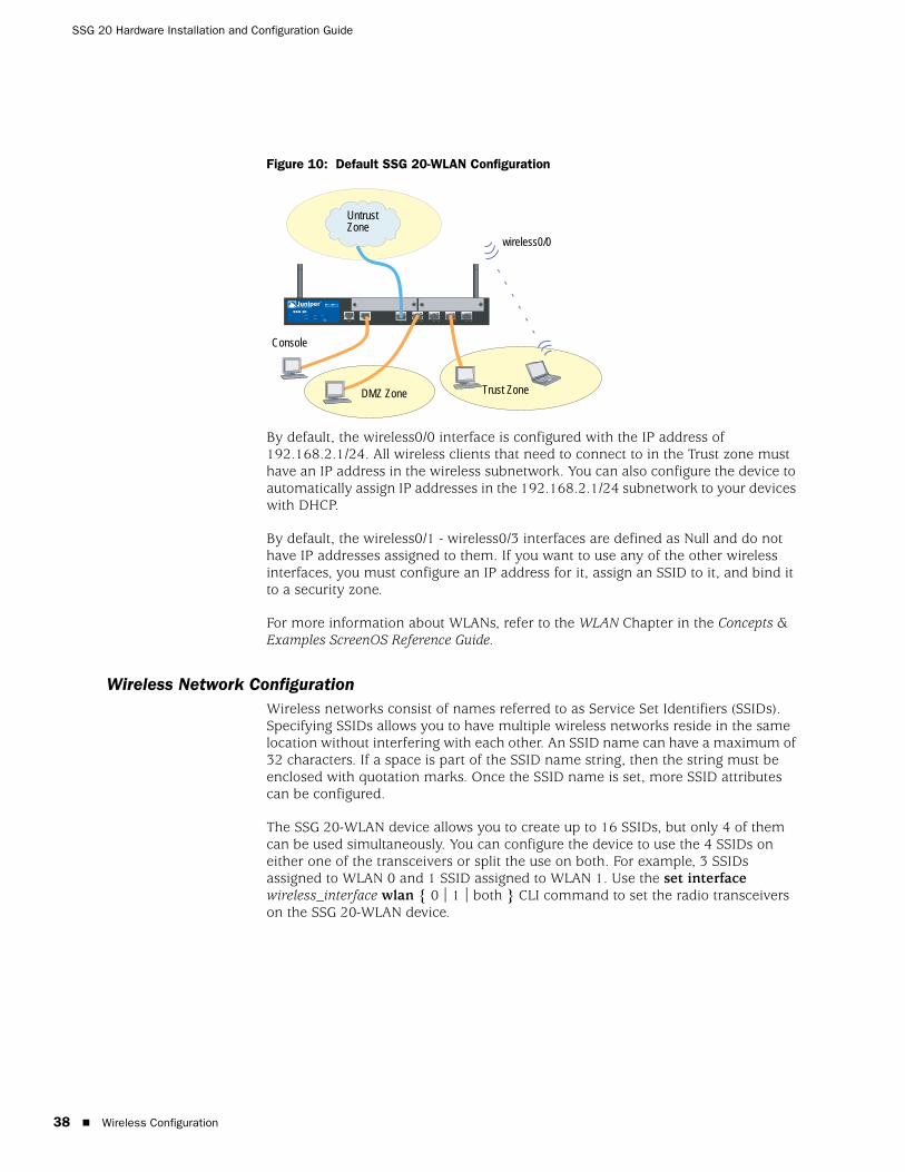
Figure 10 shows the default configuration for the SSG 20-WLAN device.
NOTE: The primary and backup interfaces must be in the same security zone. One primary interface has only one backup interface, and one backup interface has only one primary interface.
NOTE: If you are operating the SSG 20-WLAN device in a country other than the United States, Japan, Canada, China, Taiwan, Korea, Israel, or Singapore., then you must use the set wlan country-code CLI command or set it on the Wireless > General Settings WebUI page before a WLAN connection can be established. This command sets the selectable channel range and the transmit power level.
NOTE: If your regional code is ETSI, you must set the correct country code that meets you local radio spectrum regulation.
Wireless Configuration 37
SSG 20 Hardware Installation and Configuration Guide
38
Figure 10: Default SSG 20-WLAN Configuration
By default, the wireless0/0 interface is configured with the IP address of 192.168.2.1/24. All wireless clients that need to connect to in the Trust zone must have an IP address in the wireless subnetwork. You can also configure the device to automatically assign IP addresses in the 192.168.2.1/24 subnetwork to your devices with DHCP.
By default, the wireless0/1 - wireless0/3 interfaces are defined as Null and do not have IP addresses assigned to them. If you want to use any of the other wireless interfaces, you must configure an IP address for it, assign an SSID to it, and bind it to a security zone.
For more information about WLANs, refer to the WLAN Chapter in the Concepts & Examples ScreenOS Reference Guide.
Wireless Network ConfigurationWireless networks consist of names referred to as Service Set Identifiers (SSIDs). Specifying SSIDs allows you to have multiple wireless networks reside in the same location without interfering with each other. An SSID name can have a maximum of 32 characters. If a space is part of the SSID name string, then the string must be enclosed with quotation marks. Once the SSID name is set, more SSID attributes can be configured.
The SSG 20-WLAN device allows you to create up to 16 SSIDs, but only 4 of them can be used simultaneously. You can configure the device to use the 4 SSIDs on either one of the transceivers or split the use on both. For example, 3 SSIDs assigned to WLAN 0 and 1 SSID assigned to WLAN 1. Use the set interface wireless_interface wlan { 0 | 1 | both } CLI command to set the radio transceivers on the SSG 20-WLAN device.
AUX 0/0 10 /100AUX 0/0 10/100 0 /0 10/100 0/0 10 /100 0/0 10 /100
LINK
STATUS
POWER
PIM 2
PIM 1
b/g
802.11a
WLAN
SSG 20
1 2
Untrust Zone
Trust Zone
wireless0/0
Console
DMZ Zone
Wireless Configuration
To set the SSID name netscreen open, allow the SSID to be open to all users, bind the SSID to the wireless0/0 interface, and use both radio transceivers, use the WebUI or CLI:
WebUI
Wireless > SSID > New: Enter the following, then click Activate Changes:
SSID: netscreen openAuthentication: openEncryption: noneWireless Interface Binding: wireless0/0 (select)
CLI
set ssid name “netscreen open”set ssid “netscreen open” authentication open encryption noneset ssid “netscreen open” interface wireless0/0saveexec wlan reactivate
You can set an SSID to operate in the same subnet as the wired subnet. This action allows clients to work in either interface without having to reconnect in another subnet.
Wireless Configuration ExampleTo set up a wireless interface for basic wireless configuration, use the WebUI or CLI:
WebUI
1. Set the WLAN country-code and IP address
Wireless > General Settings > Select the following, then click Apply:
Country code: Select your codeIP Address/Netmask: ip_add/netmask
2. Set the SSID
Wireless > SSID > New: Enter the following, then click OK:
SSID: Authentication: Encryption: Wireless Interface Binding:
3. (optional) Set the WEP Key
SSID > WEP Keys: Select the key-id, then click Apply.
4. Set the WLAN mode
Network > Interfaces > List > Edit (wireless interface): Select Both for the WLAN mode, then click Apply.
Wireless Configuration 39
SSG 20 Hardware Installation and Configuration Guide
40
5. Activate wireless changes
Wireless > General Settings > Click Activate Changes
CLI
1. Set the WLAN country-code and IP address
set wlan country-code { code_id }set interface wireless_interface ip ip_addr/netmask
2. Set the SSID
set ssid name name_strset ssid name_str authentication auth_type encryption encryption_typeset ssid name_str interface interface(optional) set ssid name_str key-id number
3. Set the WLAN mode
set interface wireless_interface wlan both
4. Activate wireless changes
saveexec wlan reactivate
To set an ethernet and wireless interface to the same bridge group interface, use the WebUI or CLI:
WebUI
Network > Interfaces > List > Edit (bgroup_name) > Bind Port: Select the wireless and ethernet interfaces, then click Apply.
CLI
set interface bgroup_name port wireless_interfaceset interface bgroup_name port ethernet_interface
NOTE: Bgroup_name can be bgroup0—bgroup3.
Ethernet_interface can be ethernet0/0—ethernet0/4.
Wireless_interface can be wireless0/0—wireless0/3.
If a wireless interface is configured, then you need to reactivate the WLAN with the exec wlan reactivate CLI command or click Activate Changes on the Wireless > General Settings WebUI page.
Wireless Configuration
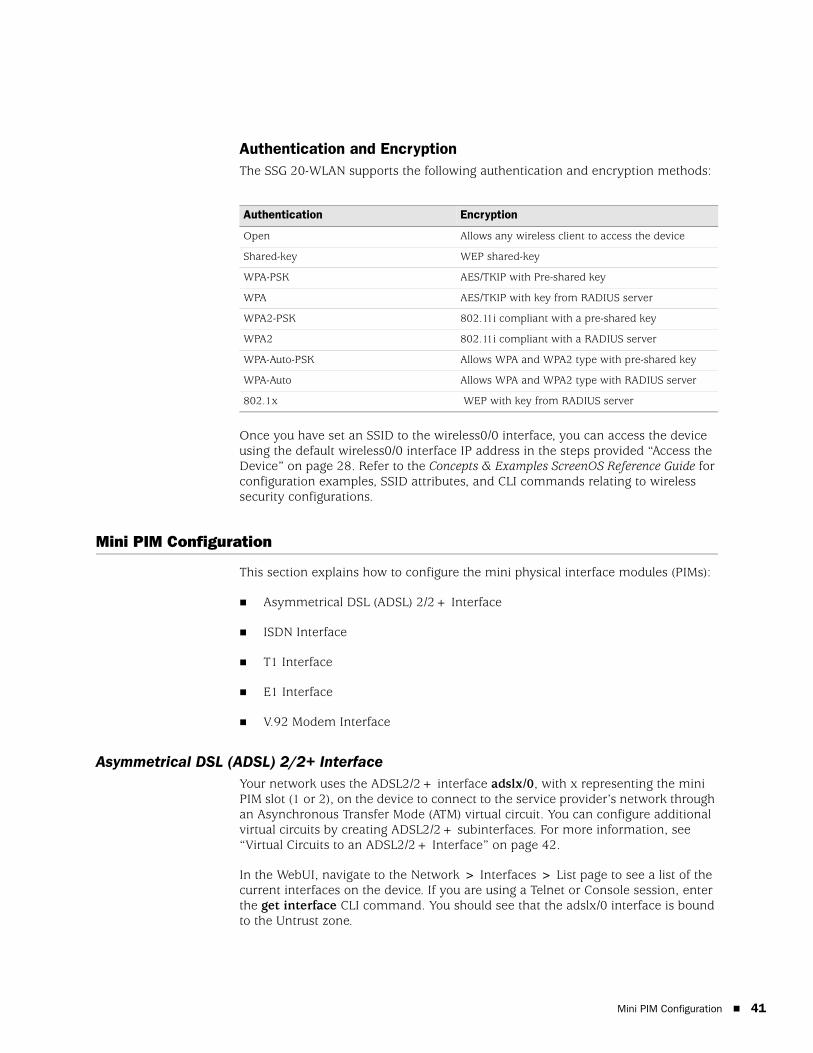
Authentication and EncryptionThe SSG 20-WLAN supports the following authentication and encryption methods:
Once you have set an SSID to the wireless0/0 interface, you can access the device using the default wireless0/0 interface IP address in the steps provided “Access the Device” on page 28. Refer to the Concepts & Examples ScreenOS Reference Guide for configuration examples, SSID attributes, and CLI commands relating to wireless security configurations.
Mini PIM Configuration
This section explains how to configure the mini physical interface modules (PIMs):
Asymmetrical DSL (ADSL) 2/2+ Interface
ISDN Interface
T1 Interface
E1 Interface
V.92 Modem Interface
Asymmetrical DSL (ADSL) 2/2+ InterfaceYour network uses the ADSL2/2+ interface adslx/0, with x representing the mini PIM slot (1 or 2), on the device to connect to the service provider’s network through an Asynchronous Transfer Mode (ATM) virtual circuit. You can configure additional virtual circuits by creating ADSL2/2+ subinterfaces. For more information, see “Virtual Circuits to an ADSL2/2+ Interface” on page 42.
In the WebUI, navigate to the Network > Interfaces > List page to see a list of the current interfaces on the device. If you are using a Telnet or Console session, enter the get interface CLI command. You should see that the adslx/0 interface is bound to the Untrust zone.
Authentication Encryption
Open Allows any wireless client to access the device
Shared-key WEP shared-key
WPA-PSK AES/TKIP with Pre-shared key
WPA AES/TKIP with key from RADIUS server
WPA2-PSK 802.11i compliant with a pre-shared key
WPA2 802.11i compliant with a RADIUS server
WPA-Auto-PSK Allows WPA and WPA2 type with pre-shared key
WPA-Auto Allows WPA and WPA2 type with RADIUS server
802.1x WEP with key from RADIUS server
Mini PIM Configuration 41

SSG 20 Hardware Installation and Configuration Guide
42
If you are using the ADSL2/2+ interface to connect to the service network of the provider, you must configure the adsl(x/0) interface. To do this, you must obtain the following information from your service provider:
Virtual Path Identifier and Virtual Channel Identifier (VPI/VCI) values
ATM Adaptation Layer 5 (AAL5) multiplexing method, which can be one of the following:
Virtual Circuit-based multiplexing, in which each protocol is carried over a separate ATM virtual circuit
Logical Link Control (LLC) encapsulation, which allows several protocols to be carried on the same ATM virtual circuit (the default multiplexing method)
Username and password assigned by the service provider for connection to the service provider’s network using either Point-to-Point Protocol over Ethernet (PPPoE) or Point-to-Point Protocol over ATM (PPPoA)
Authentication method, if any, provided for the PPPoE or PPPoA connection
Optionally, a static IP address and netmask value for your network
Virtual Circuits to an ADSL2/2+ InterfaceTo add virtual circuits, you create subinterfaces to the ADSL2/2+ interface. You can create up to 10 ADSL2/2+ subinterfaces. For example, to create a new subinterface named adsl1/0.1 bound to the predefined zone named Untrust, use the WebUI or CLI:
WebUI
Network > Interfaces > List > New ADSL Sub-IF: Enter the following, then click Apply:
Interface Name: adsl1/0.1VPI/VCI: 0/35Zone Name: Untrust (select)
CLI
set interface adsl 1/0.1 pvc 0 35 zone Untrustsave
You need to configure an ADSL 2/2+subinterface in the same way as the main ADSL2/2+ interface, including setting the VPI/VCI values, as described in “Asymmetrical DSL (ADSL) 2/2+ Interface” on page 41. You configure an ADSL2/2+ subinterface independently of the main ADSL2/2+ interface; that is, you can configure a different multiplexing method, VPI/VCI, and PPP client on the subinterface than on the main ADSL2/2+ interface. You can also configure a static IP address on a subinterface, even if the main ADSL2/2+ interface does not have a static IP address.
Mini PIM Configuration
VPI/VCI and Multiplexing MethodYour service provider assigns a VPI/VCI pair for each virtual circuit connection. For example, you may receive the VPI/VCI pair 1/32, which means a VPI value of 1 and a VCI value of 32. These values must match the values that the service provider has configured on the subscriber’s side of the Digital Subscriber Line Access Multiplexer (DSLAM).
To configure the VPI/VCI pair 1/32 on the adsl1/0 interface, use the WebUI or CLI:
WebUI
Network > Interfaces > List > Edit (for the adsl1/0 interface): Enter 1/32 in the VPI/VCI field, then click Apply.
CLI
set interface adsl1/0 pvc 1 32save
By default, the device uses LLC-based multiplexing for each virtual circuit. To configure the VPI/VCI 1/32 on the adslx/0 interface and use LLC encapsulation on the virtual circuit, use the WebUI or CLI:
WebUI
Network > Interfaces > List > Edit (for the adsl1/0 interface): Enter the following, then click Apply:
VPI/VCI: 1 / 32Multiplexing Method: LLC (selected)
CLI
set interface adsl1/0 pvc 1 32 mux llcsave
PPPoE or PPPoAAn SSG 20 device includes both PPPoE and PPPoA clients to connect to the service provider’s network over the ADSL link. PPPoE is the most common form of ADSL encapsulation and is intended for termination on each host on your network. PPPoA is used primarily for business class-service as PPP sessions can be terminated on the device. To allow the device to connect to the network of the service provider, you need to configure the username and password assigned by the service provider. The configuration for PPPoA is similar to the configuration for PPPoE.
NOTE: The device supports only one PPPoE session on each virtual circuit.
Mini PIM Configuration 43

SSG 20 Hardware Installation and Configuration Guide
44
To configure the user name roswell and password area51 for PPPoE and bind the PPPoE configuration to the adsl1/0 interface, use the WebUI or CLI:
WebUI
Network > PPP > PPPoE Profile> New: Enter the following, then click OK:
PPPoE Instance: poe1Bound to Interface: adsl1/0 (select)Username: roswellPassword: area51
CLI
set pppoe name poe1 username roswell password area51set pppoe name poe1 interface adsl1/0save
There are other PPPoE or PPPoA parameters that you can configure on the device, including method of authentication (by default, the device supports either Challenge Handshake Authentication Protocol or Password Authentication Protocol), idle timeout (default is 30 minutes), and so on. Ask your service provider if there are additional PPPoE or PPPoA parameters that you need to configure to enable proper communications with the service provider’s server.
Static IP Address and NetmaskIf your ISP gave you a specific, fixed IP address and netmask for your network, then configure the IP address and netmask for the network and the IP address of the router port connected to the device. You need to also specify that the device is to use the static IP address. (Typically, the device acts as a PPPoE or PPPoA client and receives an IP address for the ADSL interface through negotiations with the PPPoE or PPPoA server.)
You need to configure a PPPoE or PPPoA instance and bind it to the adsl1/0 interface, as described in “PPPoE or PPPoA” on page 43. Make sure that you select Obtain IP using PPPoE or Obtain IP using PPPoA and the name of the PPPoE or PPPoA instance.
To configure the static IP address 1.1.1.1/24 for the network, use the WebUI or CLI:
WebUI
Network > Interfaces > List > Edit (for the adsl1/0 interface): Enter the following, then click Apply:
IP Address/Netmask: 1.1.1.1/24Static IP: (select)
CLI
set interface adsl1/0 ip 1.1.1.1/24set pppoe name poe1 static-ipsave
or
set interface adsl1/0 ip 1.1.1.1/24set pppoa name poa1 static-ipsave
Mini PIM Configuration

To use Domain Name System (DNS) for domain name and address resolution, the computers in your network need to have the IP address of at least one DNS server. If the device receives an IP address for the ADSL2/2+ interface through PPPoE or PPPoA, then it also automatically receives IP addresses for the DNS server(s). If the computers in your network obtain their IP address(es) from the DHCP server on the device, then the computers also obtain these DNS server addresses.
If you assign a static IP address to the ADSL2/2+ interface, then the service provider must give you the IP address(es) of the DNS server(s). You can either configure the DNS server address on each computer in your network or configure the DHCP server on the Trust zone interface so that it provides the DNS server address to each computer.
To configure the DHCP server on the bgroup0 interface to provide the DNS server address 1.1.1.152 to computers in your network, use the WebUI or CLI:
WebUI
Network > DHCP > Edit (for the bgroup0 interface) > DHCP Server: Enter 1.1.1.152 for DNS1, then click Apply.
CLI
set interface bgroup0 dhcp server option dns1 1.1.1.152save
For more information about configuring the ADSL and ADSL2/2+ interfaces, refer to the Concepts & Examples ScreenOS Reference Guide.
ISDN InterfaceIntegrated Services Digital Network (ISDN) is a set of standards for digital transmission over different media created by the Consultative Committee for International Telegraphy and Telephone (CCITT) and International Telecommunications Union (ITU). As a dial-on-demand service, it has fast call setup and low latency as well as the ability to carry high-quality voice, data, and video transmissions. ISDN is also a circuit-switched service that can be used on both multipoint and point-to-point connections. ISDN provides a service router with a multi-link Point-to-Point Protocol (PPP) connection for network interfaces. The ISDN interface is usually configured as the backup interface of the Ethernet interface to access external networks.
To configure the ISDN interface, use the WebUI or CLI:
WebUI
Network > Interfaces > List > Edit (bri1/0): Enter or select the following, then click OK.
BRI Mode: Dial Using BRIPrimary Number: 123456WAN Encapsulation: PPPPPP Profile: isdnprofile
Mini PIM Configuration 45
SSG 20 Hardware Installation and Configuration Guide
46
CLI
set interface bri1/0 dialer-enableset interface bri1/0 primary-number "123456"set interface bri1/0 encap pppset interface bri1/0 ppp profile isdnprofilesave
For more information on how to configure the ISDN interface, refer to the Concepts & Examples ScreenOS Reference Guide.
To configure the ISDN interface as the backup interface, see “Backup Untrust Interface Configuration” on page 37.
T1 InterfaceThe T1 interface is a basic Physical Layer protocol used by the Digital Signal level 1 (DS-1) multiplexing method in North America. A T1 interface operates at a bit-rate of 1.544 Mbps or speeds up to 24 DS0 channels.
The devices support the following T1 DS-1 standards:
ANSI TI.107, TI.102
GR 499-core, GR 253-core
AT&T Pub 54014
ITU G.751, G.703
To configure the T1 mini PIM, use the WebUI or CLI:
WebUI
Network > Interfaces > List > Edit (serial1/0): Enter or select the following, then click OK.
WAN Configure: main linkWAN Encapsulation: cisco-hdlcClick ApplyFixed IP: (select)
IP Address/Netmask 172.18.1.1/24
CLI
set interface serial1/0 encap cisco-hdlcset interface serial1/0 ip 172.18.1.1/24
For information on how to configure the T1 interface, refer to the Concepts & Examples ScreenOS Reference Guide.
Mini PIM Configuration

E1 InterfaceThe E1 interface is a standard wide area network (WAN) digital communications format designed to operate over copper facilities at a rate of 2.048 Mbps. Widely used outside North America, E1 is a basic time-division multiplexing scheme used to carry digital circuits.
The devices support the following E1 standards:
ITU-T G.703
ITU-T G.751
ITU-T G.775
To configure the E1 mini PIM, use the WebUI or CLI:
WebUI
Network > Interfaces > List > Edit (serial1/0): Enter or select the following, then click OK.
WAN Configure: main linkWAN Encapsulation: PPPBinding a PPP Profile: junipertestClick ApplyFixed IP: (select)
IP Address/Netmask 172.18.1.1/24
CLI
set interface serial1/0 encapsulation pppset ppp profile “junipertest” static-ipset ppp profile “junipertest” auth type chapset ppp profile “junipertest” auth local-name “juniper”set ppp profile “junipertest” auth secret “password”set interface serial1/0 ppp profile “junipertest”set interface serial1/0 ip 172.18.1.1/24set user “server” type wanset user “server” password “server”
For information on how to configure the E1 interface, refer to the Concepts & Examples ScreenOS Reference Guide.
Mini PIM Configuration 47
SSG 20 Hardware Installation and Configuration Guide
48
V.92 Modem InterfaceThe V.92 interface provides an internal analog modem to establish a PPP connection to an ISP. You can configure the serial interface as a primary or backup interface, which is used in case of interface failover.
To configure the V.92 interface, use the WebUI or CLI:
WebUI
Network > Interfaces > List > Edit (for serial1/0): Enter the following, then click OK:
Zone Name: untrust (select)
ISP: Enter the following, then click OK:
ISP Name: isp_juniperPrimary Number: 1234567Login Name: juniperLogin Password: juniper
Modem: Enter the following, then click OK:
Modem Name: mod1Init String: AT&FS7=255S32=6Active Modem setting
Inactivity Timeout: 20
CLI
set interface serial1/0 zone untrustset interface serial1/0 modem isp isp_juniper account login juniper password juniperset interface serial1/0 modem isp isp_juniper primary-number 1234567set interface serial1/0 modem idle-time 20set interface serial1/0 modem settings mod1 init-strings AT&FS7=255S32=6set interface serial1/0 modem settings mod1 active
For information on how to configure the V.92 modem interface, refer to the Concepts & Examples ScreenOS Reference Guide.
NOTE: The V.92 interface does not work in transparent mode.
Mini PIM Configuration
Basic Firewall Protections
The devices are configured with a default policy that permits workstations in the Trust zone of your network to access any resource in the Untrust security zone, while outside computers are not allowed to access or start sessions with your workstations. You can configure policies that direct the device to permit outside computers to start specific kinds of sessions with your computers. For information about creating or modifying policies, refer to the Concepts & Examples ScreenOS Reference Guide.
The SSG 20 device provides various detection methods and defense mechanisms to combat probes and attacks aimed at compromising or harming a network or network resource:
ScreenOS SCREEN options secure a zone by inspecting, and then allowing or denying, all connection attempts that require crossing an interface to that zone. For example, you can apply port scan protection on the Untrust zone to stop a source from an remote network from trying to identify services to target for further attacks.
The device applies firewall policies, which can contain content filtering and intrusion detection and prevention (IDP) components, to the traffic that passes the SCREEN filters from one zone to another. By default, no traffic is permitted to pass through the device from one zone to another. To permit traffic to cross the device from one zone to another, you must create a policy that overrides the default behavior.
To set ScreenOS SCREEN options for a zone:
WebUI
Screening > Screen: Select the zone to which the options apply. Select the SCREEN options that you want, then click Apply:
CLI
set zone zone screen optionsave
For more information about configuring the network security options available in ScreenOS, see the Attack Detection and Defense Mechanisms volume in the Concepts & Examples ScreenOS Reference Guide.
Verifying External Connectivity
To verify that workstations in your network can access resources on the Internet, start a browser from any workstation in the network and enter the following URL: www.juniper.net.
Basic Firewall Protections 49
SSG 20 Hardware Installation and Configuration Guide
50
Resetting the Device to Factory Defaults
If you lose the admin password, you can reset the device to its default settings. This action destroys any existing configurations but restores access to the device.
You can restore the device to its default settings in one of the following ways:
Using a Console connection. For further information, see the Administration chapter in the Administration volume of the Concepts & Examples ScreenOS Reference Guide.
Using the reset pinhole on the back panel of the device, as described in the next section.
The Reset PinholeYou can reset the device and restore the factory default settings by pressing the reset pinhole. To perform this operation, you need to either view the device status LEDs on the front panel or start a Console session as described in “Using a Console Connection” on page 28.
To use the reset pinhole to reset and restore the default settings, do the following:
1. Locate the reset pinhole on the rear panel. Using a thin, firm wire (such as a paper clip), push the pinhole for four to six seconds and then release.
The STATUS LED blinks red. A message on the Console states that erasure of the configuration has started and the system sends an SNMP/SYSLOG alert.
2. Wait for one to two seconds.
After the first reset, the STATUS LED blinks green; the device is now waiting for the second reset. The Console message now states that the device is waiting for a second confirmation.
3. Push the reset pinhole again for four to six seconds.
The Console message verifies the second reset. The STATUS LED glows red for one-half second and then returns to the blinking green state.
The device then resets to its original factory settings. When the device resets, the STATUS LED glows red for one-half second and then glows green. The Console displays device bootup messages. The system generates SNMP and SYSLOG alerts to configured SYSLOG or SNMP trap hosts.
After the device has rebooted, the Console displays the login prompt for the device. The STATUS LED blinks green. The login for the admin name and password is netscreen.
WARNING: Resetting the device deletes all existing configuration settings and disables all existing firewall and VPN services.
Resetting the Device to Factory Defaults

If you do not follow the complete sequence, the reset process cancels without any configuration change and the console message states that the erasure of the configuration is aborted. The STATUS LED returns to blinking green. If the device did not reset, an SNMP alert is sent to confirm the failure.
Resetting the Device to Factory Defaults 51

SSG 20 Hardware Installation and Configuration Guide
52
Resetting the Device to Factory Defaults
Chapter 4
Servicing the Device
This chapter describes service and maintenance procedures for an SSG 20 device. It contains the following sections:
“Required Tools and Parts” on this page
“Replacing a Physical Interface Module” on page 53
“Memory Upgrade” on page 56
Required Tools and Parts
To replace a component on an SSG 20 device, you need the following tools and parts:
Electrostatic bag or antistatic mat
Electrostatic discharge (ESD) grounding wrist strap
Phillips screwdriver, 1/8-inch
Replacing a Physical Interface Module
Both SSG 20 models have two slots in the front panel for wide area network physical interface modules (WAN mini PIMs). Mini PIMs in an SSG 20 device can be installed and replaced. The SSG device must be powered off before you can remove or install a mini PIM.
NOTE: For safety warnings and instructions, refer to the Juniper Networks Security Products Safety Guide. The instructions in the guide warn you about situations that could cause bodily injury. Before working on any equipment, you should be aware of the hazards involved with electrical circuitry and be familiar with standard practices for preventing accidents.
CAUTION: Make sure the power is off to the device when removing a mini PIM. They are not hot-swappable.
Required Tools and Parts 53

SSG 20 Hardware Installation and Configuration Guide
54
Removing a Blank FaceplateTo maintain proper airflow through the SSG device, blank faceplates should remain over slots that do not contain mini PIMs. Do not remove a blank faceplate unless you are installing a mini PIM in its empty slot.
To remove a blank faceplate, do the following:
1. Place an electrostatic bag or antistatic mat on a flat, stable surface to place the mini PIM.
2. Attach an ESD grounding strap to your bare wrist and connect the strap to the ESD point on the chassis or to an outside ESD point if the SSG device is disconnected from earth ground.
3. Unplug the power adapter from the device. Verify that the POWER LED is off.
4. Loosen and remove the screws on each side of the faceplate using a screwdriver.
5. Remove the faceplate, then place the faceplate in the electrostatic bag or on the antistatic mat.
Removing a Mini PIMMini PIMs are installed in the front panel of the SSG device. A mini PIM weighs less than 0.2 lb (106g).
To remove a mini PIM, do the following:
1. Place an electrostatic bag or antistatic mat on a flat, stable surface to place the mini PIM.
2. Attach an ESD grounding strap to your bare wrist and connect the strap to the ESD point on the chassis or to an outside ESD point if the SSG device is disconnected from earth ground.
3. Unplug the power adapter from the device. Verify that the POWER LED is off.
4. Label the cables connected to the mini PIM so that you can later reconnect each cable to the correct mini PIM.
5. Disconnect the cables from the mini PIM.
6. If necessary, arrange the cables to prevent them from dislodging or developing stress points:
a. Secure the cables so that it they are not supporting their own weight as they hang to the floor.
b. Place any excess cables out of the way in neatly coiled loops.
c. Use fasteners to maintain the shape of the cable loops.
7. Loosen and remove the screws on each side of the mini PIM faceplate using a screwdriver.
Replacing a Physical Interface Module

8. Grasp the screws on each side of the mini PIM faceplate and slide it out of the device. Place the mini PIM in the electrostatic bag or on the antistatic mat.
Figure 11: Removing a Mini PIM
9. If you are not reinstalling a mini PIM into the emptied slot, install a blank faceplate over the slot to maintain proper airflow.
Installing a Mini PIMTo install a mini PIM, do the following:
1. Attach an ESD grounding strap to your bare wrist and connect the strap to the ESD point on the chassis or to an outside ESD point if the SSG device is disconnected from earth ground.
2. Unplug the power adapter from the device. Verify that the POWER LED is off.
3. Grasp the screws on each side of the mini PIM faceplate and align the notches in the connector at the rear of the mini PIM with the notches in the mini PIM slot in the SSG device. Then slide the mini PIM in until it lodges firmly in the device.
Figure 12: Installing a Mini PIM
4. Tighten the screws on each side of the mini PIM faceplate using a 1/8” slotted screwdriver.
5. Insert the appropriate cables into the cable connectors on the mini PIM.
CAUTION: Slide the mini PIM straight into the slot to avoid damaging the components on the mini PIM.
Replacing a Physical Interface Module 55

SSG 20 Hardware Installation and Configuration Guide
56
6. If necessary, arrange the cables to prevent them from dislodging or developing stress points:
a. Secure the cables so that they are not supporting their own weight as they hang to the floor.
b. Place any excess cables out of the way in neatly coiled loops.
c. Use fasteners to maintain the shape of the cable loops.
7. Unplug the power adapter from the device. Verify that the POWER LED glows steadily green after you press the power button.
8. Verify that the PIM status LED on the system dashboard glows steadily green to confirm that the mini PIM is online.
Memory Upgrade
You can upgrade an SSG 20 device from a single 128 MB SDIMM DRAM memory module to a 256 MB module.
To upgrade the memory on an SSG 20 device, do the following:
1. Attach an ESD grounding strap to your bare wrist and connect the strap to the ESD point on the chassis, or to an outside ESD point if the device is disconnected from earth ground.
2. Unplug the AC cord from the power outlet.
3. Turn over device so that the top of the device is laying on a flat surface.
4. Use a phillips screwdriver to remove the screws from the memory card cover. Keep the screws nearby for use when securing the cover later.
5. Remove the memory card cover.
Figure 13: Bottom of device
6. Release the 128 MB SDIMM DRAM memory module by pressing your thumbs outward on the locking tabs on each side of the module so that the tabs move away from it.
Memory Upgrade
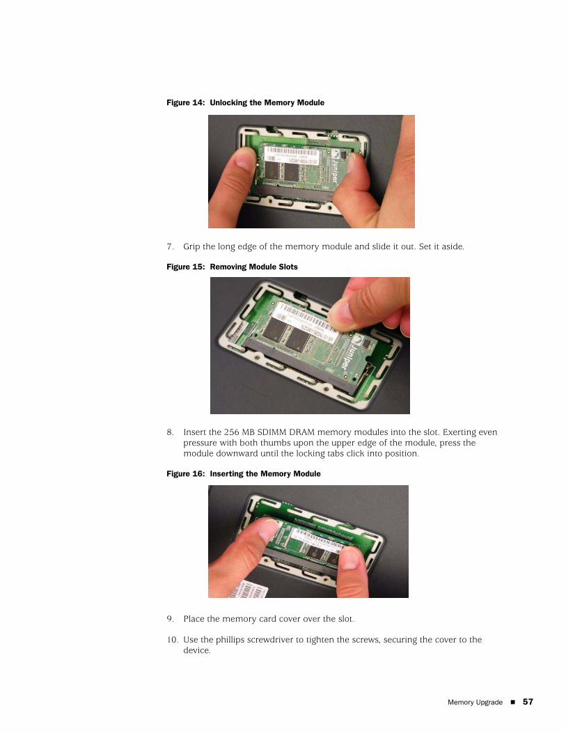
Figure 14: Unlocking the Memory Module
7. Grip the long edge of the memory module and slide it out. Set it aside.
Figure 15: Removing Module Slots
8. Insert the 256 MB SDIMM DRAM memory modules into the slot. Exerting even pressure with both thumbs upon the upper edge of the module, press the module downward until the locking tabs click into position.
Figure 16: Inserting the Memory Module
9. Place the memory card cover over the slot.
10. Use the phillips screwdriver to tighten the screws, securing the cover to the device.
Memory Upgrade 57

SSG 20 Hardware Installation and Configuration Guide
58
Memory Upgrade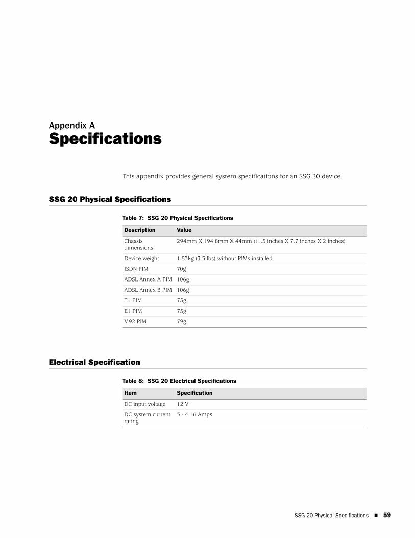
Appendix A
Specifications
This appendix provides general system specifications for an SSG 20 device.
SSG 20 Physical Specifications
Table 7: SSG 20 Physical Specifications
Electrical Specification
Table 8: SSG 20 Electrical Specifications
Description Value
Chassis dimensions
294mm X 194.8mm X 44mm (11.5 inches X 7.7 inches X 2 inches)
Device weight 1.53kg (3.3 lbs) without PIMs installed.
ISDN PIM 70g
ADSL Annex A PIM 106g
ADSL Annex B PIM 106g
T1 PIM 75g
E1 PIM 75g
V.92 PIM 79g
Item Specification
DC input voltage 12 V
DC system current rating
3 - 4.16 Amps
SSG 20 Physical Specifications 59
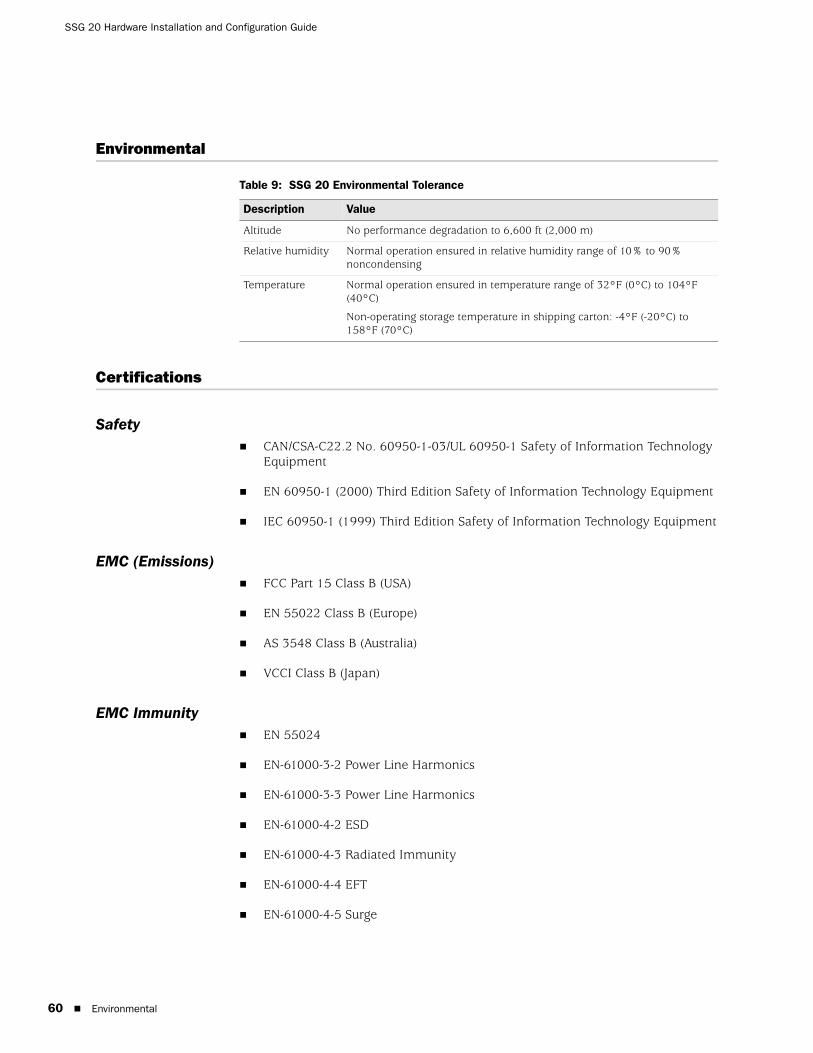
SSG 20 Hardware Installation and Configuration Guide
60
Environmental
Table 9: SSG 20 Environmental Tolerance
Certifications
SafetyCAN/CSA-C22.2 No. 60950-1-03/UL 60950-1 Safety of Information Technology Equipment
EN 60950-1 (2000) Third Edition Safety of Information Technology Equipment
IEC 60950-1 (1999) Third Edition Safety of Information Technology Equipment
EMC (Emissions)FCC Part 15 Class B (USA)
EN 55022 Class B (Europe)
AS 3548 Class B (Australia)
VCCI Class B (Japan)
EMC ImmunityEN 55024
EN-61000-3-2 Power Line Harmonics
EN-61000-3-3 Power Line Harmonics
EN-61000-4-2 ESD
EN-61000-4-3 Radiated Immunity
EN-61000-4-4 EFT
EN-61000-4-5 Surge
Description Value
Altitude No performance degradation to 6,600 ft (2,000 m)
Relative humidity Normal operation ensured in relative humidity range of 10% to 90% noncondensing
Temperature Normal operation ensured in temperature range of 32°F (0°C) to 104°F (40°C)
Non-operating storage temperature in shipping carton: -4°F (-20°C) to 158°F (70°C)
Environmental
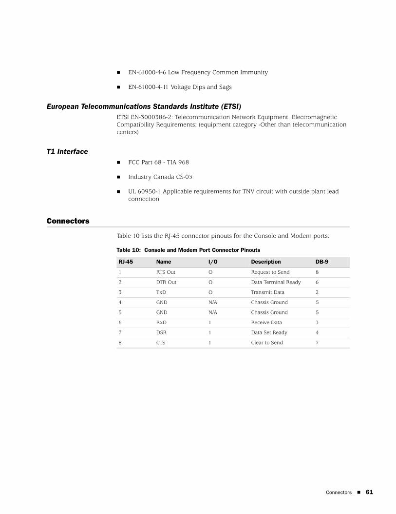
EN-61000-4-6 Low Frequency Common Immunity
EN-61000-4-11 Voltage Dips and Sags
European Telecommunications Standards Institute (ETSI)ETSI EN-3000386-2: Telecommunication Network Equipment. Electromagnetic Compatibility Requirements; (equipment category -Other than telecommunication centers)
T1 InterfaceFCC Part 68 - TIA 968
Industry Canada CS-03
UL 60950-1 Applicable requirements for TNV circuit with outside plant lead connection
Connectors
Table 10 lists the RJ-45 connector pinouts for the Console and Modem ports:
Table 10: Console and Modem Port Connector Pinouts
RJ-45 Name I/O Description DB-9
1 RTS Out O Request to Send 8
2 DTR Out O Data Terminal Ready 6
3 TxD O Transmit Data 2
4 GND N/A Chassis Ground 5
5 GND N/A Chassis Ground 5
6 RxD 1 Receive Data 3
7 DSR 1 Data Set Ready 4
8 CTS 1 Clear to Send 7
Connectors 61

SSG 20 Hardware Installation and Configuration Guide
62
Connectors
Appendix B
Initial Configuration Wizard
This appendix provides detailed information about the Initial Configuration Wizard (ICW) for an SSG 20 device.
After you have physically connected your device to the network, you can use the ICW to configure the interfaces that are installed on your device.
This section describes the following ICW windows:
1. Rapid Deployment Window on page 66
2. Administrator Login Window on page 66
3. WLAN Access Point Window on page 67
4. Physical Ethernet Interface Window on page 67
5. ADSL2/2+ Interface Window on page 68
6. T1 Interface Windows on page 69
7. E1 Interface Windows on page 74
8. ISDN Interface Windows on page 76
9. V.92 Modem Interface Window on page 78
10. Untrust Zone (Ethernet0/0 Interface) Window on page 79
11. DMZ Zone (Ethernet0/1 Interface) Window on page 80
12. Trust Zone (Ethernet0/2 Interface) Window on page 80
13. Wireless Interface (wireless0/0) in Trust Zone Window on page 81
14. Interface Summary Window on page 82
15. Physical Ethernet DHCP Interface Window on page 82
16. Wireless DHCP Interface Window on page 83
17. Confirmation Window on page 83
65
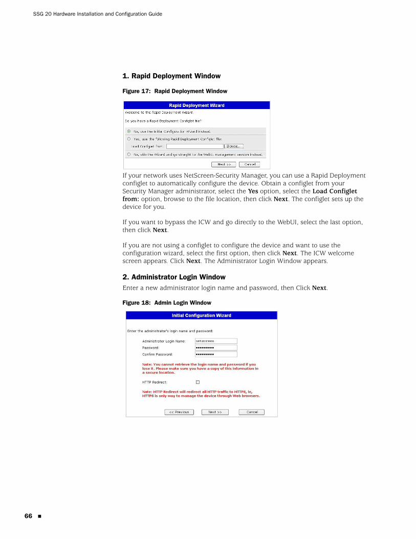
SSG 20 Hardware Installation and Configuration Guide
66
1. Rapid Deployment Window
Figure 17: Rapid Deployment Window
If your network uses NetScreen-Security Manager, you can use a Rapid Deployment configlet to automatically configure the device. Obtain a configlet from your Security Manager administrator, select the Yes option, select the Load Configlet from: option, browse to the file location, then click Next. The configlet sets up the device for you.
If you want to bypass the ICW and go directly to the WebUI, select the last option, then click Next.
If you are not using a configlet to configure the device and want to use the configuration wizard, select the first option, then click Next. The ICW welcome screen appears. Click Next. The Administrator Login Window appears.
2. Administrator Login WindowEnter a new administrator login name and password, then Click Next.
Figure 18: Admin Login Window

3. WLAN Access Point WindowIf you are using the device in the WORLD regulatory domain, you must choose a country code. Select the appropriate option, then click Next.
Figure 19: Wireless Access Point Country Code Window
4. Physical Ethernet Interface WindowOn the interface-to-zone bindings screen, you set the interface to which you want to bind the Untrust security zone. Bgroup0 is prebound to the Trust security zone. Ethernet0/1 is bound to the DMZ security zone but is optional.
Figure 20: Ethernet Interface Window
After binding an interface to a zone, you can configure the interface. The configuration windows that are displayed after this point are dependent on which mini-PIMs are installed in the device. To continue configuring your device with the ICW, click Next.
67
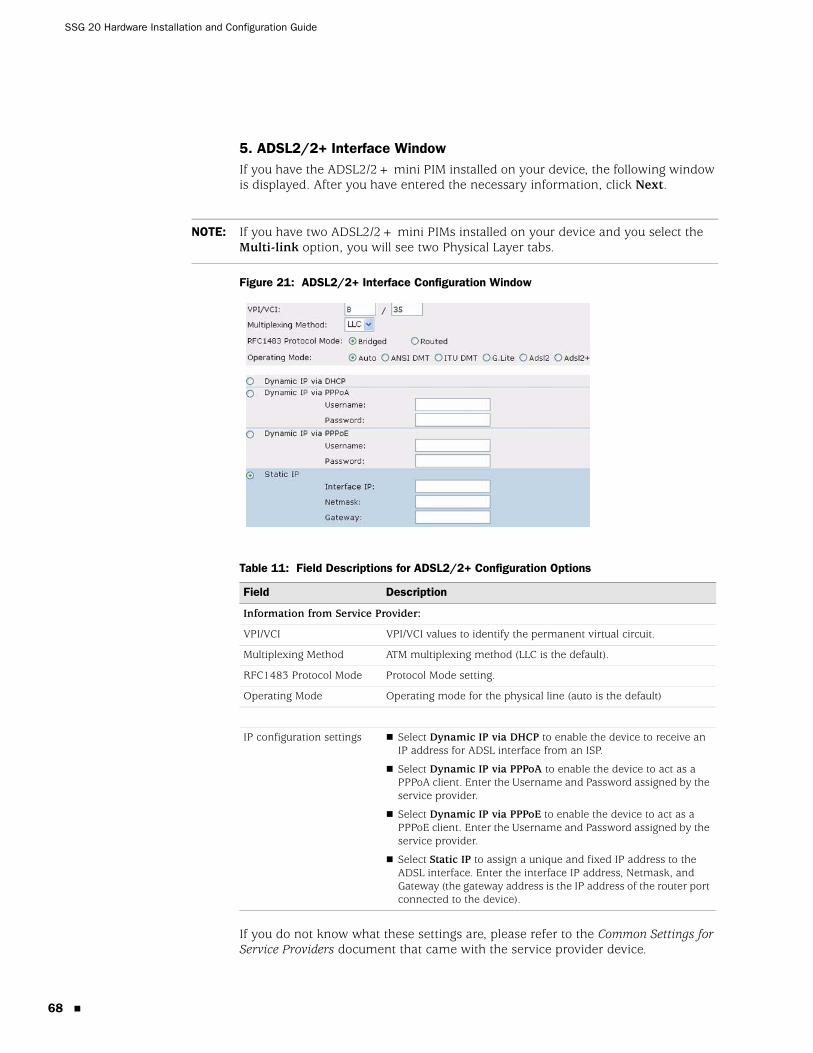
SSG 20 Hardware Installation and Configuration Guide
68
5. ADSL2/2+ Interface WindowIf you have the ADSL2/2+ mini PIM installed on your device, the following window is displayed. After you have entered the necessary information, click Next.
Figure 21: ADSL2/2+ Interface Configuration Window
Table 11: Field Descriptions for ADSL2/2+ Configuration Options
If you do not know what these settings are, please refer to the Common Settings for Service Providers document that came with the service provider device.
NOTE: If you have two ADSL2/2+ mini PIMs installed on your device and you select the Multi-link option, you will see two Physical Layer tabs.
Field Description
Information from Service Provider:
VPI/VCI VPI/VCI values to identify the permanent virtual circuit.
Multiplexing Method ATM multiplexing method (LLC is the default).
RFC1483 Protocol Mode Protocol Mode setting.
Operating Mode Operating mode for the physical line (auto is the default)
IP configuration settings Select Dynamic IP via DHCP to enable the device to receive an IP address for ADSL interface from an ISP.
Select Dynamic IP via PPPoA to enable the device to act as a PPPoA client. Enter the Username and Password assigned by the service provider.
Select Dynamic IP via PPPoE to enable the device to act as a PPPoE client. Enter the Username and Password assigned by the service provider.
Select Static IP to assign a unique and fixed IP address to the ADSL interface. Enter the interface IP address, Netmask, and Gateway (the gateway address is the IP address of the router port connected to the device).
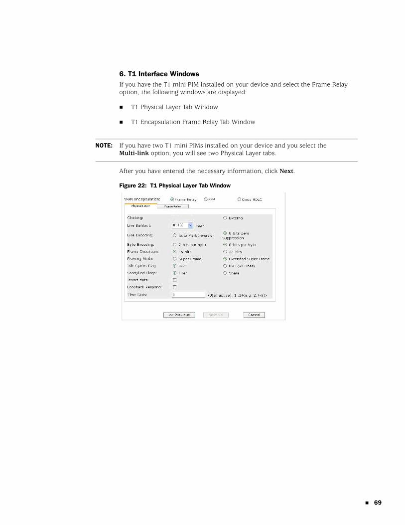
6. T1 Interface WindowsIf you have the T1 mini PIM installed on your device and select the Frame Relay option, the following windows are displayed:
T1 Physical Layer Tab Window
T1 Encapsulation Frame Relay Tab Window
After you have entered the necessary information, click Next.
Figure 22: T1 Physical Layer Tab Window
NOTE: If you have two T1 mini PIMs installed on your device and you select the Multi-link option, you will see two Physical Layer tabs.
69
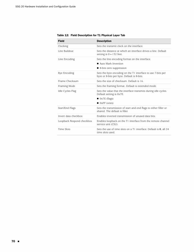
SSG 20 Hardware Installation and Configuration Guide
70
Table 12: Field Description for T1 Physical Layer Tab
Field Description
Clocking Sets the transmit clock on the interface.
Line Buildout Sets the distance at which an interface drives a line. Default setting is 0~132 feet.
Line Encoding Sets the line encoding format on the interface.
Auto Mark Inversion
8-bits zero suppression
Bye Encoding Sets the byte encoding on the T1 interface to use 7-bits per byte or 8-bits per byte. Default is 8-bits.
Frame Checksum Sets the size of checksum. Default is 16.
Framing Mode Sets the framing format. Default is extended mode.
Idle Cycles Flag Sets the value that the interface transmits during idle cycles. Default setting is 0x7E.
0x7E (flags)
0xFF (ones)
Start/End Flags Sets the transmission of start and end flags to either filler or shared. The default is filler.
Invert data checkbox Enables inverted transmission of unused data bits.
Loopback Respond checkbox Enables loopback on the T1 interface from the remote channel service unit (CSU).
Time Slots Sets the use of time slots on a T1 interface. Default is 0, all 24 time slots used.
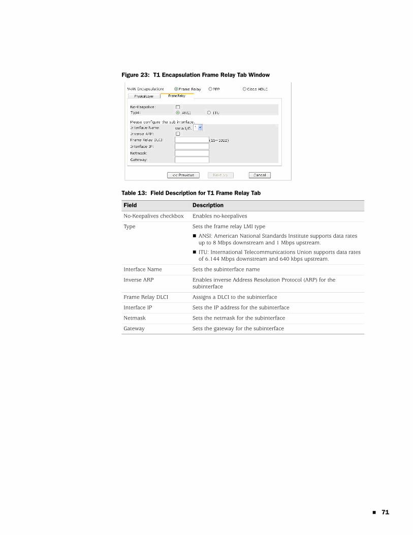
Figure 23: T1 Encapsulation Frame Relay Tab Window
Table 13: Field Description for T1 Frame Relay Tab
Field Description
No-Keepalives checkbox Enables no-keepalives
Type Sets the frame relay LMI type
ANSI: American National Standards Institute supports data rates up to 8 Mbps downstream and 1 Mbps upstream.
ITU: International Telecommunications Union supports data rates of 6.144 Mbps downstream and 640 kbps upstream.
Interface Name Sets the subinterface name
Inverse ARP Enables inverse Address Resolution Protocol (ARP) for the subinterface
Frame Relay DLCI Assigns a DLCI to the subinterface
Interface IP Sets the IP address for the subinterface
Netmask Sets the netmask for the subinterface
Gateway Sets the gateway for the subinterface
71
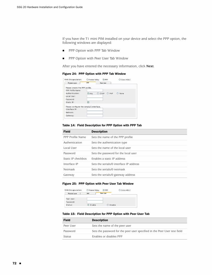
SSG 20 Hardware Installation and Configuration Guide
72
If you have the T1 mini PIM installed on your device and select the PPP option, the following windows are displayed:
PPP Option with PPP Tab Window
PPP Option with Peer User Tab Window
After you have entered the necessary information, click Next.
Figure 24: PPP Option with PPP Tab Window
Table 14: Field Description for PPP Option with PPP Tab
Figure 25: PPP Option with Peer User Tab Window
Table 15: Field Description for PPP Option with Peer User Tab
Field Description
PPP Profile Name Sets the name of the PPP profile
Authentication Sets the authentication type
Local User Sets the name of the local user
Password Sets the password for the local user
Static IP checkbox Enables a static IP address
Interface IP Sets the serialx/0 interface IP address
Netmask Sets the serialx/0 netmask
Gateway Sets the serialx/0 gateway address
Field Description
Peer User Sets the name of the peer user
Password Sets the password for the peer user specified in the Peer User text field
Status Enables or disables PPP
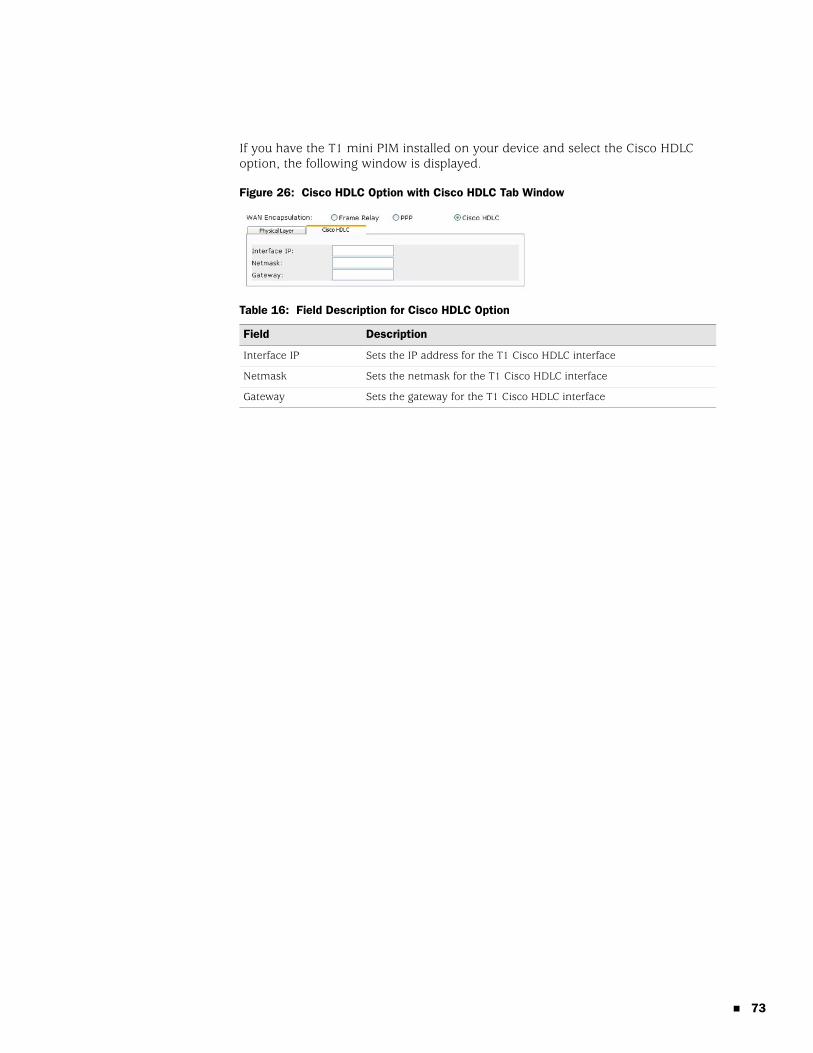
If you have the T1 mini PIM installed on your device and select the Cisco HDLC option, the following window is displayed.
Figure 26: Cisco HDLC Option with Cisco HDLC Tab Window
Table 16: Field Description for Cisco HDLC Option
Field Description
Interface IP Sets the IP address for the T1 Cisco HDLC interface
Netmask Sets the netmask for the T1 Cisco HDLC interface
Gateway Sets the gateway for the T1 Cisco HDLC interface
73
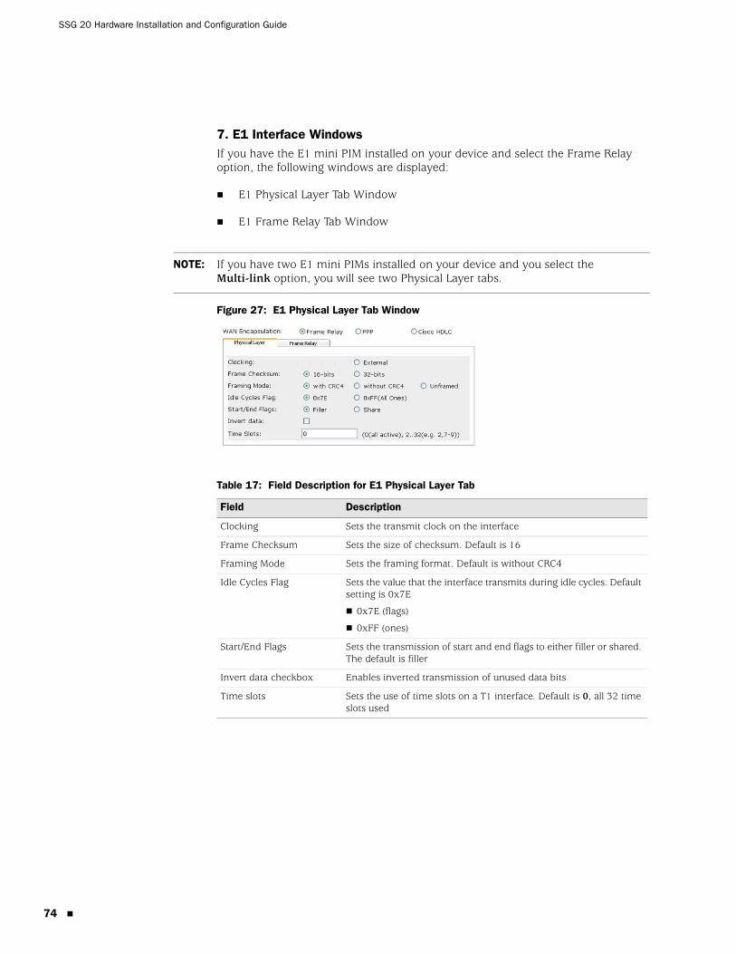
SSG 20 Hardware Installation and Configuration Guide
74
7. E1 Interface WindowsIf you have the E1 mini PIM installed on your device and select the Frame Relay option, the following windows are displayed:
E1 Physical Layer Tab Window
E1 Frame Relay Tab Window
Figure 27: E1 Physical Layer Tab Window
Table 17: Field Description for E1 Physical Layer Tab
NOTE: If you have two E1 mini PIMs installed on your device and you select the Multi-link option, you will see two Physical Layer tabs.
Field Description
Clocking Sets the transmit clock on the interface
Frame Checksum Sets the size of checksum. Default is 16
Framing Mode Sets the framing format. Default is without CRC4
Idle Cycles Flag Sets the value that the interface transmits during idle cycles. Default setting is 0x7E
0x7E (flags)
0xFF (ones)
Start/End Flags Sets the transmission of start and end flags to either filler or shared. The default is filler
Invert data checkbox Enables inverted transmission of unused data bits
Time slots Sets the use of time slots on a T1 interface. Default is 0, all 32 time slots used
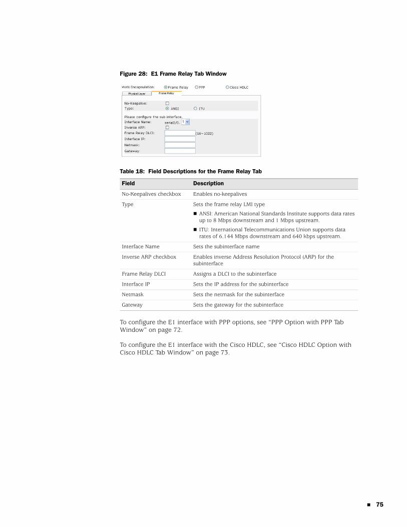
Figure 28: E1 Frame Relay Tab Window
Table 18: Field Descriptions for the Frame Relay Tab
To configure the E1 interface with PPP options, see “PPP Option with PPP Tab Window” on page 72.
To configure the E1 interface with the Cisco HDLC, see “Cisco HDLC Option with Cisco HDLC Tab Window” on page 73.
Field Description
No-Keepalives checkbox Enables no-keepalives
Type Sets the frame relay LMI type
ANSI: American National Standards Institute supports data rates up to 8 Mbps downstream and 1 Mbps upstream.
ITU: International Telecommunications Union supports data rates of 6.144 Mbps downstream and 640 kbps upstream.
Interface Name Sets the subinterface name
Inverse ARP checkbox Enables inverse Address Resolution Protocol (ARP) for the subinterface
Frame Relay DLCI Assigns a DLCI to the subinterface
Interface IP Sets the IP address for the subinterface
Netmask Sets the netmask for the subinterface
Gateway Sets the gateway for the subinterface
75
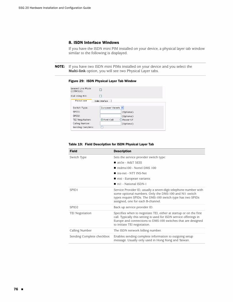
SSG 20 Hardware Installation and Configuration Guide
76
8. ISDN Interface WindowsIf you have the ISDN mini PIM installed on your device, a physical layer tab window similar to the following is displayed.
Figure 29: ISDN Physical Layer Tab Window
Table 19: Field Description for ISDN Physical Layer Tab
NOTE: If you have two ISDN mini PIMs installed on your device and you select the Multi-link option, you will see two Physical Layer tabs.
Field Description
Switch Type Sets the service provider switch type:
att5e - At&T 5ESS
ntdms100 - Nortel DMS 100
ins-net - NTT INS-Net
etsi - European variants
ni1 - National ISDN-1
SPID1 Service Provider ID, usually a seven-digit telephone number with some optional numbers. Only the DMS-100 and NI1 switch types require SPIDs. The DMS-100 switch type has two SPIDs assigned, one for each B-channel.
SPID2 Back up service provider ID.
TEI Negotiation Specifies when to negotiate TEI, either at startup or on the first call. Typically this setting is used for ISDN service offerings in Europe and connections to DMS-100 switches that are designed to initiate TEI negotiation.
Calling Number The ISDN network billing number.
Sending Complete checkbox Enables sending complete information to outgoing setup message. Usually only used in Hong Kong and Taiwan.
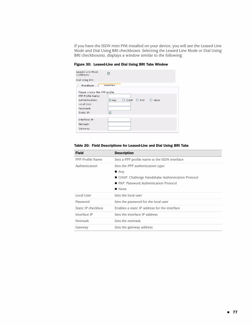
If you have the ISDN mini PIM installed on your device, you will see the Leased Line Mode and Dial Using BRI checkboxes. Selecting the Leased Line Mode or Dial Using BRI checkbox(es), displays a window similar to the following:
Figure 30: Leased-Line and Dial Using BRI Tabs Window
Table 20: Field Descriptions for Leased-Line and Dial Using BRI Tabs
Field Description
PPP Profile Name Sets a PPP profile name to the ISDN interface
Authentication Sets the PPP authentication type:
Any
CHAP: Challenge Handshake Authentication Protocol
PAP: Password Authentication Protocol
None
Local User Sets the local user
Password Sets the password for the local user
Static IP checkbox Enables a static IP address for the interface
Interface IP Sets the interface IP address
Netmask Sets the netmask
Gateway Sets the gateway address
77
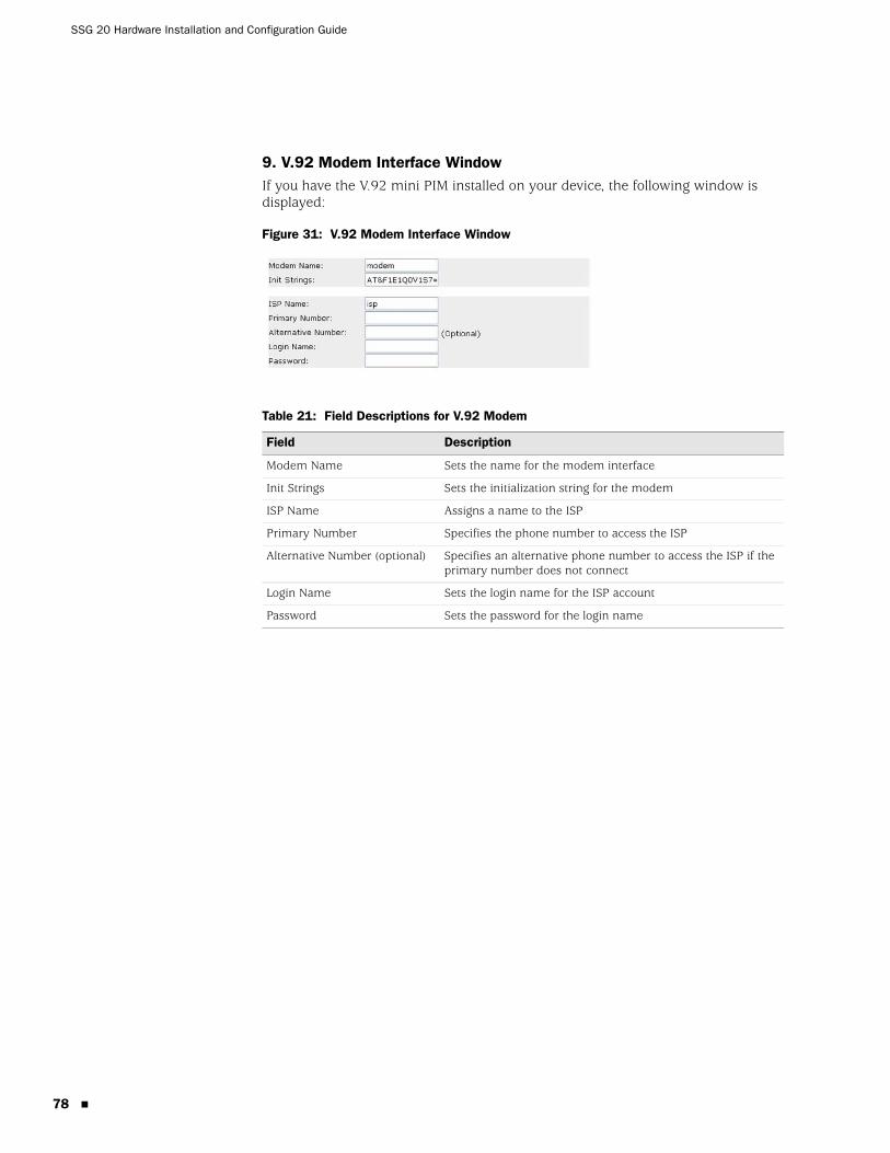
SSG 20 Hardware Installation and Configuration Guide
78
9. V.92 Modem Interface WindowIf you have the V.92 mini PIM installed on your device, the following window is displayed:
Figure 31: V.92 Modem Interface Window
Table 21: Field Descriptions for V.92 Modem
Field Description
Modem Name Sets the name for the modem interface
Init Strings Sets the initialization string for the modem
ISP Name Assigns a name to the ISP
Primary Number Specifies the phone number to access the ISP
Alternative Number (optional) Specifies an alternative phone number to access the ISP if the primary number does not connect
Login Name Sets the login name for the ISP account
Password Sets the password for the login name
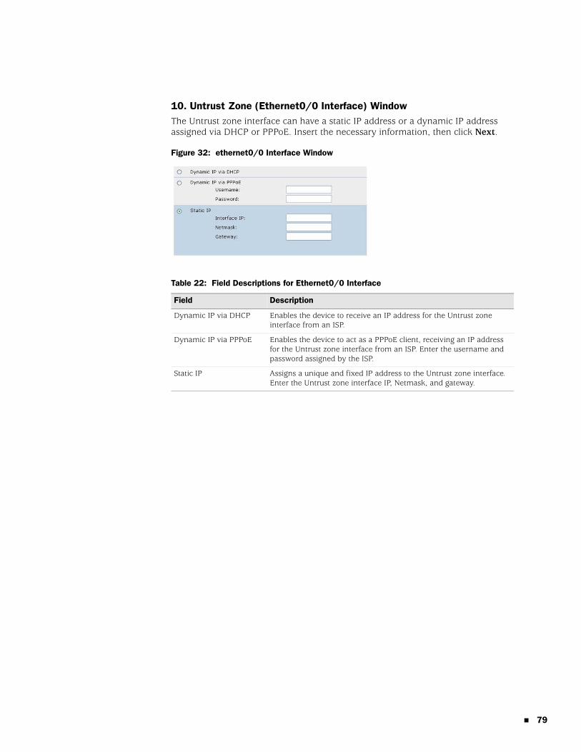
10. Untrust Zone (Ethernet0/0 Interface) WindowThe Untrust zone interface can have a static IP address or a dynamic IP address assigned via DHCP or PPPoE. Insert the necessary information, then click Next.
Figure 32: ethernet0/0 Interface Window
Table 22: Field Descriptions for Ethernet0/0 Interface
Field Description
Dynamic IP via DHCP Enables the device to receive an IP address for the Untrust zone interface from an ISP.
Dynamic IP via PPPoE Enables the device to act as a PPPoE client, receiving an IP address for the Untrust zone interface from an ISP. Enter the username and password assigned by the ISP.
Static IP Assigns a unique and fixed IP address to the Untrust zone interface. Enter the Untrust zone interface IP, Netmask, and gateway.
79
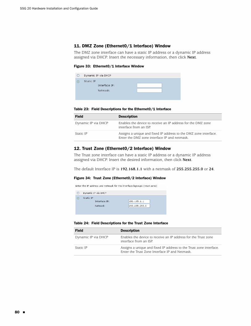
SSG 20 Hardware Installation and Configuration Guide
80
11. DMZ Zone (Ethernet0/1 Interface) WindowThe DMZ zone interface can have a static IP address or a dynamic IP address assigned via DHCP. Insert the necessary information, then click Next.
Figure 33: Ethernet0/1 Interface Window
Table 23: Field Descriptions for the Ethernet0/1 Interface
12. Trust Zone (Ethernet0/2 Interface) WindowThe Trust zone interface can have a static IP address or a dynamic IP address assigned via DHCP. Insert the desired information, then click Next.
The default Interface IP is 192.168.1.1 with a netmask of 255.255.255.0 or 24.
Figure 34: Trust Zone (Ethernet0/2 Interface) Window
Table 24: Field Descriptions for the Trust Zone Interface
Field Description
Dynamic IP via DHCP Enables the device to receive an IP address for the DMZ zone interface from an ISP.
Static IP Assigns a unique and fixed IP address to the DMZ zone interface. Enter the DMZ zone interface IP and netmask.
Field Description
Dynamic IP via DHCP Enables the device to receive an IP address for the Trust zone interface from an ISP.
Static IP Assigns a unique and fixed IP address to the Trust zone interface. Enter the Trust Zone Interface IP and Netmask.
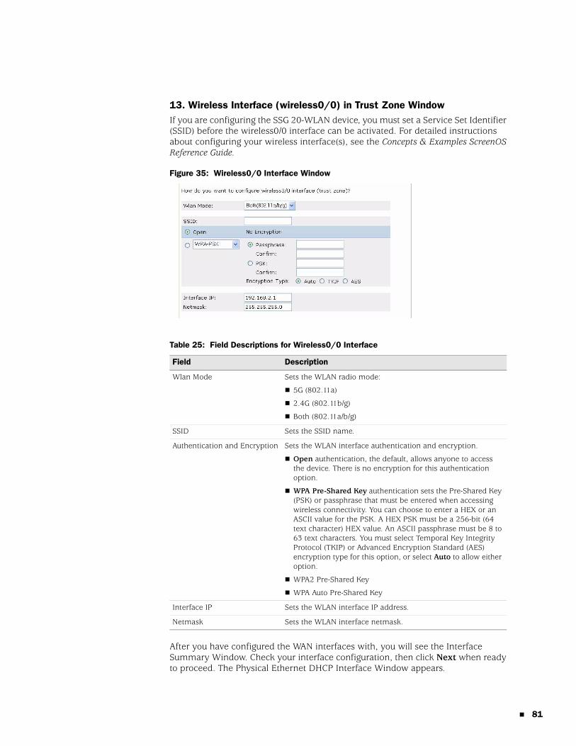
13. Wireless Interface (wireless0/0) in Trust Zone WindowIf you are configuring the SSG 20-WLAN device, you must set a Service Set Identifier (SSID) before the wireless0/0 interface can be activated. For detailed instructions about configuring your wireless interface(s), see the Concepts & Examples ScreenOS Reference Guide.
Figure 35: Wireless0/0 Interface Window
Table 25: Field Descriptions for Wireless0/0 Interface
After you have configured the WAN interfaces with, you will see the Interface Summary Window. Check your interface configuration, then click Next when ready to proceed. The Physical Ethernet DHCP Interface Window appears.
Field Description
Wlan Mode Sets the WLAN radio mode:
5G (802.11a)
2.4G (802.11b/g)
Both (802.11a/b/g)
SSID Sets the SSID name.
Authentication and Encryption Sets the WLAN interface authentication and encryption.
Open authentication, the default, allows anyone to access the device. There is no encryption for this authentication option.
WPA Pre-Shared Key authentication sets the Pre-Shared Key (PSK) or passphrase that must be entered when accessing wireless connectivity. You can choose to enter a HEX or an ASCII value for the PSK. A HEX PSK must be a 256-bit (64 text character) HEX value. An ASCII passphrase must be 8 to 63 text characters. You must select Temporal Key Integrity Protocol (TKIP) or Advanced Encryption Standard (AES) encryption type for this option, or select Auto to allow either option.
WPA2 Pre-Shared Key
WPA Auto Pre-Shared Key
Interface IP Sets the WLAN interface IP address.
Netmask Sets the WLAN interface netmask.
81
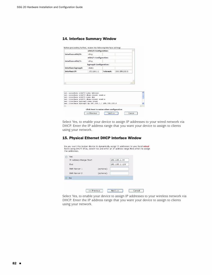
SSG 20 Hardware Installation and Configuration Guide
82
14. Interface Summary Window
Select Yes, to enable your device to assign IP addresses to your wired network via DHCP. Enter the IP address range that you want your device to assign to clients using your network.
15. Physical Ethernet DHCP Interface Window
Select Yes, to enable your device to assign IP addresses to your wireless network via DHCP. Enter the IP address range that you want your device to assign to clients using your network.

16. Wireless DHCP Interface Window
Confirm your device configuration and change as needed. Click Next to save, reboot the device, then run the configuration.
17. Confirmation Window
83

SSG 20 Hardware Installation and Configuration Guide
84

Index
AAAL5 multiplexing.........................................................42adding virtual circuit .....................................................42ADSLconfiguring interface ...............................................41connecting the cable ...............................................24connecting the port .................................................24
Annex A ..........................................................................24Annex B ..........................................................................24antennae.........................................................................26ATM Adaptation Layer 5...............................................42
Bbackup interface to Untrust zone ................................37
Ccables
ADSL..........................................................................25basic network connections.....................................24serial ..........................................................................24
certificationsEMC (Emissions) ......................................................60EMC Immunity.........................................................60European Telecommunications Standards Institute
(ETSI) ......................................................................61safety.........................................................................60T1 Interface ..............................................................61
configurationadmin name and password....................................33administrative access ..............................................35ADSL 2/2+ mini-PIM ..............................................41backup untrust interface.........................................37bridge groups (bgroup)............................................34date and time ...........................................................34default route .............................................................36E1 mini-PIM..............................................................47host and domain name...........................................36ISDN mini-PIM .........................................................45management address..............................................36management services .............................................35T1 mini-PIM..............................................................46USB ............................................................................19V.92 Modem mini-PIM............................................48virtual circuits...........................................................42VPI/VCI pair ..............................................................43
wireless and ethernet combined............................40wireless authentication and encryption ................41wireless example .....................................................39
connectionbasic network ...........................................................24
Ddefault ip addresses.......................................................32
IISP IP address and netmask.........................................44
LLEDs
activity link on Ethernet ports................................15PIM 1 .........................................................................14PIM 2 .........................................................................14POWER .....................................................................14STATUS .....................................................................14
Mmanagement services ...................................................35managing
through a console ....................................................28through a Telnet connection...................................30through the WebUI ..................................................29
memory upgrade procedure ........................................56Mini-PIM
blank faceplate .........................................................54installation ................................................................55removal .....................................................................54
mounting installationdesk-mount...............................................................22front-mount ..............................................................22wall-mount................................................................22
multiplexing, configuring..............................................43
PPoint-to-Point Protocol over ATM
See PPPoAPoint-to-Point Protocol over Ethernet
See PPPoEports and power connector descriptions ....................12PPPoA .............................................................................42PPPoE..............................................................................42
Index 85
86
SSG 20 Hardware Installation and Configuration Guide
Rradio transceivers
WLAN 0..................................................................... 18WLAN 1..................................................................... 18
reset pinhole, using....................................................... 50
Sserial port
auxiliary .................................................................... 15Console ..................................................................... 15
static IP address............................................................. 42
UUntrust zone, configuring backup interface............... 37
Vvirtual circuit, adding .................................................... 42Virtual Path Identifier/Virtual Channel Identifier
See VPI/VCIVPI/VCI
configuring ............................................................... 43values ........................................................................ 42
WWireless
antennae................................................................... 26using the default interface...................................... 26
WLAN LEDs802.11a..................................................................... 14b/g..............................................................................14
Index