Embed Size (px)
Citation preview

EMC® VMAX®
Securing Kit Installation Guide
For:VMAX3™ Family: VMAX 100K, 200K, 400KVMAX All Flash: 250F, 450F, 850FREVISION 04

Copyright © 2014-2016 EMC Corporation. All rights reserved. Published in the USA.
Published September 2016
EMC believes the information in this publication is accurate as of its publication date. The information is subject to changewithout notice.
The information in this publication is provided as is. EMC Corporation makes no representations or warranties of any kind withrespect to the information in this publication, and specifically disclaims implied warranties of merchantability or fitness for aparticular purpose. Use, copying, and distribution of any EMC software described in this publication requires an applicablesoftware license.
EMC², EMC, and the EMC logo are registered trademarks or trademarks of EMC Corporation in the United States and othercountries. All other trademarks used herein are the property of their respective owners.
For the most up-to-date regulatory document for your product line, go to EMC Online Support (https://support.emc.com).
EMC CorporationHopkinton, Massachusetts 01748-91031-508-435-1000 In North America 1-866-464-7381www.EMC.com
2 Securing Kit Installation Guide For: VMAX3 Family: VMAX 100K, 200K, 400K VMAX All Flash: 250F, 450F, 850F

Preface 5
Revision history...............................................................................................8
Securing Kit Overview 9
Installation overview..................................................................................... 10Required Tools................................................................................. 10Securing Kit contents....................................................................... 10Types of brackets............................................................................. 11Task overview.................................................................................. 13
Laying out the securing brackets................................................................... 14Dimensions and layout.................................................................... 14
Hole drilling requirements............................................................................. 18Hole dimensions - VMAX 250F.......................................................................19Hole dimensions - VMAX3 Family and VMAX 450F/VMAX 850F...................... 21
Bracket Installation 23
Installing brackets.........................................................................................24Securing the bay to the floor..........................................................................26
Nonraised floor................................................................................ 26Raised floor......................................................................................26
Chapter 1
Chapter 2
CONTENTS
Securing Kit Installation Guide For: VMAX3 Family: VMAX 100K, 200K, 400K VMAX All Flash: 250F, 450F, 850F 3

CONTENTS
4 Securing Kit Installation Guide For: VMAX3 Family: VMAX 100K, 200K, 400K VMAX All Flash: 250F, 450F, 850F

Preface
Contact your EMC technical support professional if a product does not function properlyor does not function as described in this document.
Note
This document was accurate at publication time. Go to EMC Online Support (https://support.emc.com) to ensure that you are using the latest version of this document.
PurposeThis document describes how to install Securing Kits for:l VMAX3 Family: VMAX 100K, VMAX 200K, VMAX 400Kl VMAX All Flash: VMAX 250F, VMAX 450F, VMAX 450FX, VMAX 850F, VMAX 850FX
AudienceThis document is intended for customers who are installing Securing Kits for theirVMAX3 Family or VMAX All Flash system bays.
Related documentationThe following EMC publications provide additional information:
EMC VMAX3 Family Product Guide for VMAX 100K, VMAX 200K, VMAX 400K with HYPERMAXOS
Provides product information regarding the purchase of a VMAX3 Family 100K, 200K,400K.
EMC VMAX All Flash Product Guide for VMAX 250F, 450F, 850F with HYPERMAX OS
Provides product information regarding the purchase of a VMAX 250F, 450F, 850Fwith HYPERMAX OS.
EMC VMAX3 Family Site Planning Guide for VMAX 100K, VMAX 200K, VMAX 400K withHYPERMAX OS
Provides planning information regarding the purchase and installation of a VMAX3Family 100K, 200K, 400K.
EMC VMAX All Flash Site Planning Guide for VMAX 250F, 450F, 850F with HYPERMAX OS
Provides planning information regarding the purchase and installation of a VMAX250F, 450F, 850F with HYPERMAX OS.
EMC VMAX Best Practices Guide for AC Power Connections
Describes the best practices to assure fault-tolerant power to a VMAX3 Family arrayor VMAX All Flash array.
EMC VMAX Power-down/Power-up Procedure
Describes how to power-down and power-up a VMAX3 Family array or VMAX All Flasharray.
SolVe Desktop
Provides links to documentation, procedures for common tasks, and connectivityinformation for 2-site and 3-site SRDF configurations. To download the SolVeDesktop tool, go to EMC Online Support at https://support.EMC.com and search forSolVe Desktop. Download the SolVe Desktop and load the VMAX All Flash, VMAX3Family, VMAX, and DMX procedure generator.
Preface 5

Note
You need to authenticate (authorize) your SolVe Desktop. After it is installed,familiarize yourself with the information under Help tab.
Special notice conventions used in this documentEMC uses the following conventions for special notices:
DANGER
Indicates a hazardous situation which, if not avoided, will result in death or seriousinjury.
WARNING
Indicates a hazardous situation which, if not avoided, could result in death or seriousinjury.
CAUTION
Indicates a hazardous situation which, if not avoided, could result in minor or moderateinjury.
NOTICE
Addresses practices not related to personal injury.
Note
Presents information that is important, but not hazard-related.
Typographical conventionsEMC uses the following type style conventions in this document:
Table 1 Typographical conventions used in this content
Bold Used for names of interface elements, such as names of windows,dialog boxes, buttons, fields, tab names, key names, and menu paths(what the user specifically selects or clicks)
Italic Used for full titles of publications referenced in text
Monospace Used for:
l System code
l System output, such as an error message or script
l Pathnames, filenames, prompts, and syntax
l Commands and options
Monospace italic Used for variables
Monospace bold Used for user input
[ ] Square brackets enclose optional values
| Vertical bar indicates alternate selections - the bar means “or”
{ } Braces enclose content that the user must specify, such as x or y or z
Preface
6 Securing Kit Installation Guide For: VMAX3 Family: VMAX 100K, 200K, 400K VMAX All Flash: 250F, 450F, 850F

Table 1 Typographical conventions used in this content (continued)
... Ellipses indicate nonessential information omitted from the example
Where to get helpEMC support, product, and licensing information can be obtained as follows:
Product information
EMC technical support, documentation, release notes, software updates, orinformation about EMC products can be obtained on the https://support.emc.comsite (registration required).
Technical support
To open a service request through the https://support.emc.com site, you must havea valid support agreement. Contact your EMC sales representative for details aboutobtaining a valid support agreement or to answer any questions about your account.
eLicensing support
To activate your entitlements and obtain your VMAX license files, visit the ServiceCenter on https://support.EMC.com, as directed on your License Authorization Code(LAC) letter emailed to you.
l For help with missing or incorrect entitlements after activation (that is, expectedfunctionality remains unavailable because it is not licensed), contact your EMCAccount Representative or Authorized Reseller.
l For help with any errors applying license files through Solutions Enabler, contactthe EMC Customer Support Center.
l If you are missing a LAC letter, or require further instructions on activating yourlicenses through the Online Support site, contact EMC's worldwide Licensingteam at [email protected] or call:
n North America, Latin America, APJK, Australia, New Zealand: SVC4EMC(800-782-4362) and follow the voice prompts.
n EMEA: +353 (0) 21 4879862 and follow the voice prompts.
EMC SolVe Desktop
Provides links to documentation, procedures for common tasks, and connectivityinformation for 2-site and 3-site SRDF configurations. To download the SolVeDesktop tool, go to EMC Online Support at https://support.EMC.com and search forSolVe Desktop. Download the SolVe Desktop and load the VMAX All Flash, VMAX3Family, VMAX, and DMX procedure generator.
Note
You need to authenticate (authorize) your SolVe Desktop. After it is installed,familiarize yourself with the information under Help tab.
Your commentsYour suggestions help us improve the accuracy, organization, and overall quality of thedocumentation. Send your comments and feedback to: [email protected]
Preface
7

Revision historyThe following table presents the revision history of this document:
Revision Description and/orChange
Date
04 Added information forVMAX 250F.
September, 2016
03 Update name and docreferences. Minor edits forclarity.
February, 2016
02 Update name and docreferences.
September, 2015
01 Initial release September, 2014
Preface
8 Securing Kit Installation Guide For: VMAX3 Family: VMAX 100K, 200K, 400K VMAX All Flash: 250F, 450F, 850F
CHAPTER 1
Securing Kit Overview
This section provides an overview of securing kits installation process for a VMAX array.
Topics include:
l Installation overview............................................................................................. 10l Laying out the securing brackets........................................................................... 14l Hole drilling requirements..................................................................................... 18l Hole dimensions - VMAX 250F...............................................................................19l Hole dimensions - VMAX3 Family and VMAX 450F/VMAX 850F.............................. 21
Securing Kit Overview 9

Installation overviewSome customers require that their EMC equipment be installed to withstand significantshock and vibration. Installation of Securing Kits, in combination with adequatesubstrate construction, can mitigate collateral damage during such events.
The Securing Kits contain heavy floor and top brackets for the system bays. The floorbrackets are attached to the floor using bolts that engage the flooring substructure withinthe computer room or data center. The top brackets secure the tops of adjacent bays.
Securing Kits can be installed on system bays without lifting the bays.
Table 2 Securing Kit part numbers
VMAX 250F VMAX3 Family and VMAX All Flash 450F, 850F Description
ES-SECURE E-SECURE Single bay
ES-SECUREJK E-SECUREADD Joining bays
Required ToolsThe following tools are required to complete the installation of the securing kits.
Table 3 Required Tools
Tool Uses
Power drill Drilling holes for floor brackets.
1/2” (1.27cm) drill bit Drilling holes for floor brackets.
Tape measure To measure hole locations.
Socket wrench kit, imperial Installing bracket fasteners.
Securing Kit contents
Table 4 Single bay kits
Kit Contents (Qty)
E-SECURE Anti-move bracket, front/rear (floor) securing brackets, short (2)
Seismic restraint bracket, right/left (floor) securing brackets, long (2)
Black oxide steel extra thick flat washer (12)
Screw, hex cap, grade 8, black oxide, 3/8-1 (12)
ES-SECURE Front and rear (floor) securing brackets
Right and left (floor) securing brackets
Securing screws and washers
Securing Kit Overview
10 Securing Kit Installation Guide For: VMAX3 Family: VMAX 100K, 200K, 400K VMAX All Flash: 250F, 450F, 850F
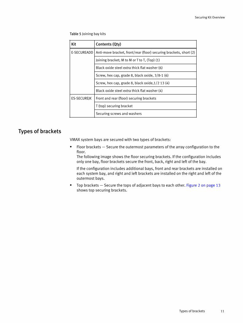
Table 5 Joining bay kits
Kit Contents (Qty)
E-SECUREADD Anti-move bracket, front/rear (floor) securing brackets, short (2)
Joining bracket; M to M or T to T, (Top) (1)
Black oxide steel extra thick flat washer (6)
Screw, hex cap, grade 8, black oxide, 3/8-1 (6)
Screw, hex cap, grade 8, black oxide,1/2 13 (4)
Black oxide steel extra thick flat washer (4)
ES-SECUREJK Front and rear (floor) securing brackets
T (top) securing bracket
Securing screws and washers
Types of bracketsVMAX system bays are secured with two types of brackets:
l Floor brackets — Secure the outermost parameters of the array configuration to thefloor.The following image shows the floor securing brackets. If the configuration includesonly one bay, floor brackets secure the front, back, right and left of the bay.
If the configuration includes additional bays, front and rear brackets are installed oneach system bay, and right and left brackets are installed on the right and left of theoutermost bays.
l Top brackets — Secure the tops of adjacent bays to each other. Figure 2 on page 13shows top securing brackets.
Securing Kit Overview
Types of brackets 11

Figure 1 Floor securing brackets
SYM-002822
Left/rightbracket
Front/rearbracket
Hex screw, flat washer
(3 each bracket) Front/rearbracket
Hex screw, flat washer
(3 each bracket)
Securing Kit Overview
12 Securing Kit Installation Guide For: VMAX3 Family: VMAX 100K, 200K, 400K VMAX All Flash: 250F, 450F, 850F

Figure 2 Top securing brackets
SYM-002823
Hex screw (4 on T-brackets)Flat washer (4 each on all T-brackets)
System bay
System bay
T-bracket between system bays
System bay
T-bracket betweensystem bays
Task overviewInstalling Securing Kits involves:
l Understanding the system layout and the position of the floor and top brackets thatsecure the system.
l Positioning brackets and drilling holes in the computer room floor to accommodatebracket securing bolts.
l Securing the system bays.
Securing Kit Overview
Task overview 13

Laying out the securing bracketsTo layout the securing brackets on raised or unraised floors, you must understand thelayout and dimensions of the system bays.
System bays are the same size. System bays are secured to the floor with floor brackets,and along the top with T brackets.
Floor brackets are attached directly to raised or non raised floors.
Dimensions and layoutOn arrays with system bay 1 only, the system bay is secured to the floor with a front, rear,right and left bracket.
On systems with multiple, adjacent bays, bays are secured with:
l A front and rear bracket on each bay
l A right and left bracket on the outermost bays
l An upper T bracket between bays (secures the top)
Securing Kit Overview
14 Securing Kit Installation Guide For: VMAX3 Family: VMAX 100K, 200K, 400K VMAX All Flash: 250F, 450F, 850F

Single system bayThe following image shows how to position securing brackets on an array with singlesystem bay.
Figure 3 System placement, single system bay
SYM-002821
Left/rightbracket
Front/rearbracket
Securing Kit Overview
Dimensions and layout 15

Multiple system baysThe following image shows how to position a VMAX 250F system with securing bracketson unraised floors.
Figure 4 VMAX 250F system bay placement, unraised floors
Note: Dimensions are in inches and centimeters
Front
Rear
Cement !oor
0.25 (.64) Gap
between cabinets
24 (61)
42 (106.7)
Service area
42 (106.7)
Service area
42 (106.7)
Service area
sec_nonraised
42 (106.7)
Service area
24 (61)
The following image shows how to position a VMAX 250F system with securing bracketson raised floors.
Figure 5 VMAX 250F system bay placement, raised floors
A A
Front
Rear
Floor tiles
24 (61) sq.
0.25 (0.64) Gap
between cabinets
24 (61)
42 (106.7)
Service area
42 (106.7)
Service area
42 (106.7)
Service area
42 (106.7)
Service area
24 (61)
Note:
Typical tiles are 24 in. (61 cm) by 24 in. (61 cm).
Typical cutouts are 8 in. (20.3 cm) by 6 in. (15.2 cm) maximum.
Typical cutouts are 9 in. (22.9 cm) from the front and
rear of the tile.
Typical cutouts are centered on the tiles, 9 in. (22.9 cm)
from the front and rear and 8 in. (20.3 cm) from sides.
There is a .25 in. (.64 cm) gap between bays.
There is a 42 in. (106.7 cm) service area front
and rear on both the storage bay and system bay.
Securing Kit Overview
16 Securing Kit Installation Guide For: VMAX3 Family: VMAX 100K, 200K, 400K VMAX All Flash: 250F, 450F, 850F
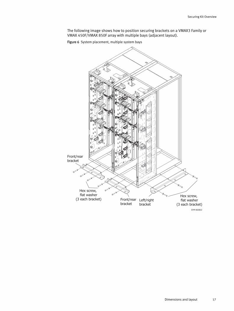
The following image shows how to position securing brackets on a VMAX3 Family orVMAX 450F/VMAX 850F array with multiple bays (adjacent layout).
Figure 6 System placement, multiple system bays
SYM-002822
Left/rightbracket
Front/rearbracket
Hex screw, flat washer
(3 each bracket) Front/rearbracket
Hex screw, flat washer
(3 each bracket)
Securing Kit Overview
Dimensions and layout 17

Hole drilling requirementsInstalling floor brackets requires the drilling of holes that affix the floor brackets directlyto a raised or non raised floor.
When drilling holes:
l Remove system bay doors for easier access.
l To maximize pullout force and transverse stability, EMC recommends securing allbrackets, and all holes within each bracket.
l Make sure the floor can be drilled without compromising its strength.It may be necessary to reinforce the floor. Contact the flooring contractor/supplier orbuilding engineer to determine the best way to proceed.
l Raised floors do not offer significant resistive strength. On a raised floor, the anchorbolts should go through the raised floor and be tied using cables and turnbuckles, orfastened directly with high strength threaded fasteners into the subfloor or superstructure on the subfloor.
Note
One method to locate the holes accurately is to mount the anchor brackets loosely to thesystem bays, using the instructions in the following sections. Mark the hole locations inpencil, and then remove the brackets and drill the holes.
l Drilled holes should be of 1/2-inch diameter (1.27cm) or larger.If you are mounting the system bays on a nonraised floor, the diameter of the holesmust be large enough to take 1/2-inch threaded inserts. Install the inserts in themanner recommended by the manufacturer. EMC recommends a proprietaryfastening system, such as HILTI, for use on nonraised floors.
For a raised-floor installation, drill the holes 5/8-inch (1.59cm) diameter. This sizeallows for any tolerance buildup in the hole pattern.
Securing Kit Overview
18 Securing Kit Installation Guide For: VMAX3 Family: VMAX 100K, 200K, 400K VMAX All Flash: 250F, 450F, 850F

Hole dimensions - VMAX 250FThe following image shows the hole dimensions for a VMAX 250F array in inches.
Figure 7 VMAX 250F drilling hole dimensions (inches)
23.93 .06
System bay
frame dimension
23.93 .06
System bay
frame dimension
.38 Dimension
between cabs
37.00 .06
Frame
dimension
1.91
1.9123.32
31.78
16.92
8.46
4
40.24+ .18
- .30
.5
.62
.81
12.45
40.81
24.90
18.67
6.22
7.82
Note: Dimensions are in inches
.81
48.24 .180
Frame stack up dimension with
.380 between frames
Securing Kit Overview
Hole dimensions - VMAX 250F 19

The following image shows the dimensions for VMAX 250F array drilling holes incentimeters.
Figure 8 VMAX 250F drilling hole dimensions (centimeters)
93.98 0.15
Frame
dimension
4.84
4.8458.96
42.98
21.49
102.20+ 0.46
- 0.76
1.27
1.59
2.06
31.62
103.67
63.25
47.43
15.81
19.88
Note: Dimensions are in centimeters
2.06
59.41 .0.15
System bay
frame dimension
59.41 .0.15
System bay
frame dimension
122.52 0.46
Frame stack up dimension with
.380 between frames
10.2
80.72
Securing Kit Overview
20 Securing Kit Installation Guide For: VMAX3 Family: VMAX 100K, 200K, 400K VMAX All Flash: 250F, 450F, 850F

Hole dimensions - VMAX3 Family and VMAX 450F/VMAX 850FThe following image shows the hole dimensions for a VMAX3 Family or VMAX 450F/VMAX 850F array in inches.Figure 9 VMAX3 Family or VMAX 450F/VMAX 850F drilling hole dimensions (inches)
23.93 .06System bay
frame dimension
23.93 .06System bay
frame dimension
.38 Dimensionbetween cabs
42.00 .06Frame
dimension
1.91
SYM-002824
1.91
23.32
31.78
16.92
8.46
4
40.24+ .18
.5
.62
.81
19.94
46.00
29.91
9.97
7.88
Note: Dimensions are in inches
.81
- .30
Frame stack up dimension with .380 between frames
48.24 .18
Securing Kit Overview
Hole dimensions - VMAX3 Family and VMAX 450F/VMAX 850F 21

The following image shows the dimensions for VMAX3 Family or VMAX 450F/VMAX 850Farray drilling holes in centimeters.
Figure 10 VMAX3 Family or VMAX 450F/VMAX 850F drilling hole dimensions (centimeters)
60.78 .15System bay
frame dimension
60.78 .15System bay
frame dimension
.965 dimensionbetween cabs
106.68 .15Frame
dimension
4.85
4.85
59.23
80.72
42.97
21.4910.16
102.21+ .45
1.27
1.57
2.06
50.65
116.84
75.97
25.32
20.01
Note: Dimensions are in centimeters
2.06
- .76
Frame stack up dimension with .965 between frames
122.53 .46
Securing Kit Overview
22 Securing Kit Installation Guide For: VMAX3 Family: VMAX 100K, 200K, 400K VMAX All Flash: 250F, 450F, 850F

CHAPTER 2
Bracket Installation
This section provides specific instructions regarding the installation of the securingbrackets for a system bay.
Topics include:
l Installing brackets.................................................................................................24l Securing the bay to the floor..................................................................................26
Bracket Installation 23

Installing bracketsTo install brackets on a system bay:
Procedure
1. If desired, remove bay doors for easier access to the floor.
2. At the rear of the system bay, loosely attach a front/rear bracket to the bay frameusing three 3/8 ID flat washers and three 3/8-16X1.5L hex cap screws, as shown inthe following image.
Figure 11 Attach floor brackets to system bays
SYM-002822
Left/rightbracket
Front/rearbracket
Hex screw, flat washer
(3 each bracket) Front/rearbracket
Hex screw, flat washer
(3 each bracket)
3. At the front of the system bay, loosely attach a front/rear bracket to the bay frameusing three 3/8 ID flat washers and three 3/8-16X1.5L hex cap screws.
4. At the rear of the adjacent bay, if present, loosely attach a bracket to the bay frameusing three 3/8 ID flat washers and three 3/8-6X1.5L hex cap screws, as shown in theprevious image.
Bracket Installation
24 Securing Kit Installation Guide For: VMAX3 Family: VMAX 100K, 200K, 400K VMAX All Flash: 250F, 450F, 850F

5. At the front of the adjacent bay, loosely attach a front/rear bracket to the bay frameusing three 3/8 ID flat washers and three 3/8-16X1.5L hex cap screws.
6. Repeat step 1 through step 4 to secure additional bays.
7. When all front and rear brackets are installed, attach a left/right bracket to each sideof the outer bays using three 3/8 ID flat washers and three 3/8-16X1.5L hex capscrews, as shown in the previous image.
8. Align one T-bracket with the installation holes at the top of each two bays to beconnected, as shown in the following image.
Figure 12 Install joining brackets between bays
SYM-002823
Hex screw (4 on T-brackets)Flat washer (4 each on all T-brackets)
System bay
System bay
T-bracket between system bays
System bay
T-bracket betweensystem bays
9. Secure the T-bracket to the bays using four 1/2 ID flat washers and four 1/2-13x1.25Lhex cap screws.
10. Repeat step 6 and step 7 until all bays are connected to each other.
11. Tighten all screws on the front, rear, and side brackets.
Bracket Installation
Installing brackets 25

Securing the bay to the floorThis section provides guidelines to fasten the system bays with brackets, previouslyinstalled on the bays, to the floor.
Nonraised floorTo fasten a bay to a nonraised floor, the following guidelines are provided:
Procedure
1. Make sure the holes on the brackets line up with the inserts you installed in the floor.
2. Fasten the brackets with 1/2-inch diameter grade 8 bolts to the inserts you installedin the floor.
3. Repeat step 1 and step 2 for all bays.
4. Reinstall all bay doors.
Raised floorTo fasten the bays to a raised floor, the following guidelines are provided:
Procedure
1. Make sure the holes on the brackets line up with the holes you drilled in the floor.
2. Fasten the brackets to the floor using 1/2-inch diameter grade 8 bolts, to a substrateor reinforcing member beneath the floor.
3. Repeat steps 1 and step 2 for all bays.
4. Reinstall all bay doors.
Bracket Installation
26 Securing Kit Installation Guide For: VMAX3 Family: VMAX 100K, 200K, 400K VMAX All Flash: 250F, 450F, 850F