Embed Size (px)
Citation preview
Securing Wireless Networks from ARP Cache
Poisoning
A Project
Presented to
The Faculty of the Department of Computer Science
San Jose State University
In partial Fulfillment
of the Requirements for the Degree
Master of Computer Science
By
Roney Philip
May 2007

APPROVED FOR THE DEPARTMENT OF COMPUTER SCIENCE
_____________________________________________________________
Dr. Mark Stamp
____________________________________________________________
Dr. Robert Chun
_____________________________________________________________
Dr. Jon Pearce
_____________________________________________________________
APPROVED FOR THE UNIVERSITY
Roney Philip
CS298 Report SJSU
i
ABSTRACT
Securing Wireless Networks from ARP Cache Poisoning
by Roney Philip
Wireless networks have become an integral part of today’s networks. The ease
of deployment, low cost, mobility and high data rates have contributed
significantly to their popularity. The medium of data transmission in wireless
networks makes them inherently less secure than wired networks. For wireless
networks to access the Internet they must be connected to a wired network via
an Access Point or a wireless router. This has led wireless network equipment
manufacturers to implement wireless Access Points and wireless routers with a
built in switch for wired clients and a WiFi access point for wireless clients. The
set up within the equipment is such that the wired and wireless networks are
internally bridged together such that they are in a single Local Area Network
(LAN). This mix of wired and wireless networks poses a new class of attacks on
wired networks via insecure wireless LANs. One such class of attack is the
Address Resolution Protocol (ARP) Cache Poisoning attack. Depending on the
wireless LAN set-up, previously secure wired networks may become vulnerable
to attacks from wireless clients in the same LAN as the wired client.
My project aims to develop a solution to prevent ARP Cache Poisoning attacks in
a wireless Access Point-based network, involving wireless and wired clients. I
have proposed a design to prevent ARP cache poisoning attacks and, as a proof-
of-concept, have implemented the design in a Wireless router manufactured by
Linksys.

Roney Philip
CS298 Report SJSU
ii
ACKNOWLEDGEMENTS
I would like to thank Dr. Mark Stamp, for his guidance, inspiration and
patience throughout the course of my project, without which this project would
have been impossible.
I would also like to express my sincere gratitude to my family for the support
and encouragement rendered to me to undertake this project. Above all, I am
indebted to God for the strength and wisdom He’s given me during this project.
Roney Philip
CS298 Report SJSU
iii
TABLE OF CONTENTS
1. INTRODUCTION........................................................ 1
2. BACKGROUND......................................................... 3
2.1 ADDRESS RESOLUTION PROTOCOL (ARP)...........................................3
2.2 ARP CACHE POISONING ....................................................................9
2.3 WIRELESS NETWORKS ......................................................................11
2.4 ARP CACHE POISONING IN WIRELESS NETWORKS .............................14
2.5 PRIOR RESEARCH ............................................................................19
3. DESIGN.................................................................... 21
3.1 DESIGN GOALS ................................................................................21
3.2 THE DESIGN ....................................................................................22
3.3 ALGORITHM .....................................................................................28
4. IMPLEMENTATION................................................. 29
4.1 HARDWARE .....................................................................................30
4.2 OPENWRT FIRMWARE ......................................................................32
4.3 CODE PLACEMENT............................................................................33
4.4 IMPLEMENTATION DETAILS ................................................................35
5. TEST CASES AND RESULTS ................................ 38
5.1 ATTACK SCENARIOS TESTED .............................................................39
5.2 IMPACT ON PERFORMANCE ...............................................................44
6. CONCLUSIONS AND FUTURE WORK.................. 46
REFERENCES ............................................................. 48
Roney Philip
CS298 Report SJSU
iv
INDEX OF FIGURES
Figure 1: The architecture of the TCP/IP reference model…….……………….…………...4
Figure 2: Operation of ARP when the command ‘ftp 10.40.68.22’ is typed….......….…… 6
Figure 3: Format of an ARP message……………………………………..………………… 7
Figure 4: ARP message in an Ethernet header………………………..…………………… 8
Figure 5: Host C performing the ARP poisoning attack on Host A and Host B….………10
Figure 6: Man-in-the-middle attack………………………………….………………………. 10
Figure 7: Infrastructure mode………………………………….……………………………. 12
Figure 8: Adhoc mode………………………………………….………………………………13
Figure 9: General set-up of wireless network with the wired network.……………………15
Figure 10: Wireless client attacking wired clients...…………………………………………16
Figure 11: Wireless client attacking a wired client and a wireless client…………….…...16
Figure 12: Attacking wireless clients……………………………………………...……….…17
Figure 13: Attacking roaming wireless hosts…………………………………...…………...17
Figure 14: Combined home gateway device………………………………...……………...19
Figure 15: Attacking two wired clients via a wireless client in a home deployment….….19
Figure 16: Attacking a wired client and a wireless client in a home network………….…20
Figure 17: Timeline diagram of DHCP messages exchanged…………………………….23
Figure 18: Format of a DHCP message……………….………………...………….……….24
Figure 19: WRT54GL wireless router……………………………………………….………..30
Figure 20: Internal diagram of the OpenWrt firmware…………………………….………..34
Figure 21: Structure of sk_buff……………………………………………………….…….…36
Figure 22: Attacking wired clients from wireless client…………………………….…….…39
Figure 23: ARP cache of Host A before the attack………………………………….….…..40
Figure 24: ARP cache of Host B before the attack………………………………….….…..40
Figure 25: ARP cache of Host A after the attack……………………………………..…….41
Figure 26: ARP cache of Host B after the attack…………………………………….….….41
Figure 27: ARP cache of Host A when arp_patrol_agent() is enabled……….……..……42
Figure 28: ARP cache of Host B when arp_patrol_agent() is enabled….………….….…42
Figure 29: Attacking a wireless and a wired client……………….……………………..…..43
Figure 30: ARP cache of Host B before the attack…………….…………………..……….43
Roney Philip
CS298 Report SJSU
v
Figure 31: ARP cache of Host B after the attack………….………..………………………44
Figure 32: ARP cache of Host B when arp_patrol_agent is enabled……..………….….44
Figure 33: Round trip time measurement for ARP request-reply in ms…..…..………….45
Figure 34: Percentage overhead………………………....…………………..…..…………..46
Roney Philip
CS298 Report SJSU
1
1. INTRODUCTION
Wireless networks have gained considerable momentum in businesses,
government offices, hot spots and even buildings requiring high security.
Wireless networks use radio waves to transmit data. Hence any device located
within the range of the network and having a wireless network interface card can
potentially read the data. In a wired network a machine needs to be physically
connected to the network; such connection points are typically protected by
physical security measures such as those associated with the perimeters of a
building. However, with a wireless network, in many cases it is not possible to
restrict the range of the radio waves to the exact perimeters of physical security.
This makes wireless networks more vulnerable to attacks than wired networks.
Various security schemes like Wired Equivalent Privacy (WEP) and Wi-Fi
Protected Access (WPA) have been employed to encrypt the data transmitted
within a wireless network. Even with these schemes in place, a class of attacks
known as Address Resolution Protocol (ARP) Cache Poisoning is still achievable
as this class of attack and the above-mentioned encryption schemes are in two
different layers of the Transport Control Protocol/Internet Protocol (TCP/IP)
network architecture model.
Wireless networks communicate to each other and the Internet via an
Access Point (AP) or a wireless router. The AP needs to be connected to a
backbone wired network in order to connect its wireless clients to the Internet. In
order to achieve this setup the AP is connected to a switch, which serves wired
clients as shown in Figure 9. This enables the wireless clients to access the
Internet just like the wired clients connected to this switch. Many network
equipment manufacturers also provide this setup within a single device by
providing a built-in switch for wired clients, a built-in AP for wireless clients and a
built-in router which is to be connected to a modem that connects to the Internet
as shown in Figure 14. The AP is internally connected to the switch via a bridge.
A bridge is a device that connects different network interfaces at the data link
layer (Layer 2) of the Open Systems Interconnection (OSI) network architecture
Roney Philip
CS298 Report SJSU
2
model. The OSI model and its various layers are explained in Section 2. Here,
the bridge forwards traffic from the wireless network to the wired network after
converting the 802.11 wireless packets into 802.3 Ethernet packets and vice
versa. Due to the presence of the bridge between the AP and the switch, all the
clients connected to the switch and the AP are in a single Local Area Network
(LAN). Hence, any broadcast packet sent from a wireless client will reach not
only the wireless clients connected to the AP but also all the wired clients
connected to the switch. This setup introduces a possible vulnerability in the
wired network by exposing it to ARP Cache Poisoning attacks from the wireless
clients.
ARP Cache Poisoning is a Layer 2 attack. In order for this attack to take
place the attacker should have access to the LAN. The attacker should be
connected directly or indirectly to any layer 2 device such as a switch, hub or
bridge.
The aim of this project was to find a way to prevent ARP Cache Poisoning
from wireless networks. According to Fleck, B. et al [1], the approaches to
prevent ARP Cache Poisoning from wireless networks are the following:
a. Redesigning the network architecture
b. Redesigning or upgrading Access Point hardware and firmware
c. Deploying VPN solutions
In this project I have taken the approach (b), of upgrading the Access Point
firmware to prevent ARP cache poisoning from wireless networks.
The report is organized as follows:
• Section 2 gives the necessary background on the OSI and TCP/IP network
architecture models, the ARP protocol and how an ARP cache poisoning
attack is conducted. It also provides background on wireless networks and
illustrates how ARP cache poisoning is achieved in wireless networks. This
section also describes prior research done in solving ARP cache poisoning
and some of their disadvantages.
• Section 3 defines the goals for our design, a description of the design itself
and the components involved in the design.
Roney Philip
CS298 Report SJSU
3
• Section 4 explains the implementation details of our design.
• Section 5 presents the test cases emulated in a real life network with a
Linksys WRT54GL wireless router and the results obtained with and without
the design.
• Section 6 outlines the contributions, presents some limitations and suggests
future work for this project.
2. BACKGROUND
2.1 Address Resolution Protocol (ARP)
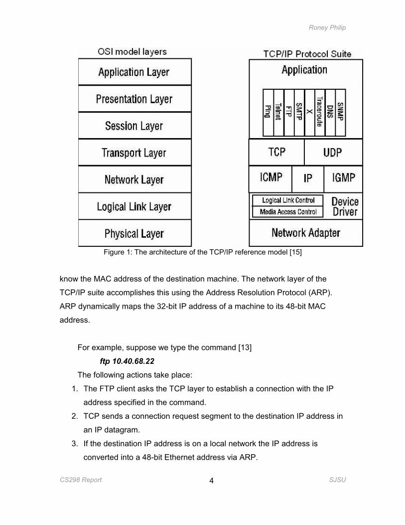
The Open Systems Interconnection (OSI) model, the standard model of
network architecture, contains seven layers, as shown in Figure 1 [15]. Today,
most real world networks use the TCP/IP model of network architecture. Figure 1
places the OSI model and the TCP/IP model side-by-side to show how the
different layers of the TCP/IP model fall within the layering conventions of the
OSI model. The figure also places the different protocols in the TCP/IP model
based on the layer in which they operate.
The layers are numbered 1-7 from the bottom up. For example, the physical
layer is layer 1 and the Application layer is layer 7. In the Network layer or layer 3
of TCP/IP suite, a host is identified by its IP address, a 32-bit number. But the
Medium Access Control (MAC) layer or layer 2 of the TCP/IP suite follows a
different addressing scheme. An interface in the MAC layer is identified by a 48-
bit MAC address.
When layer 3 receives a packet from the higher layers it checks the IP
address of the destination machine. If the destination machine is in the same
local network as that of the sending machine, the packet can be sent directly to
the destination machine; else the IP packet has to be routed via a router. To
send the packet directly to the destination machine, the network layer needs to
Roney Philip
CS298 Report SJSU
4
Figure 1: The architecture of the TCP/IP reference model [15]
know the MAC address of the destination machine. The network layer of the
TCP/IP suite accomplishes this using the Address Resolution Protocol (ARP).
ARP dynamically maps the 32-bit IP address of a machine to its 48-bit MAC
address.
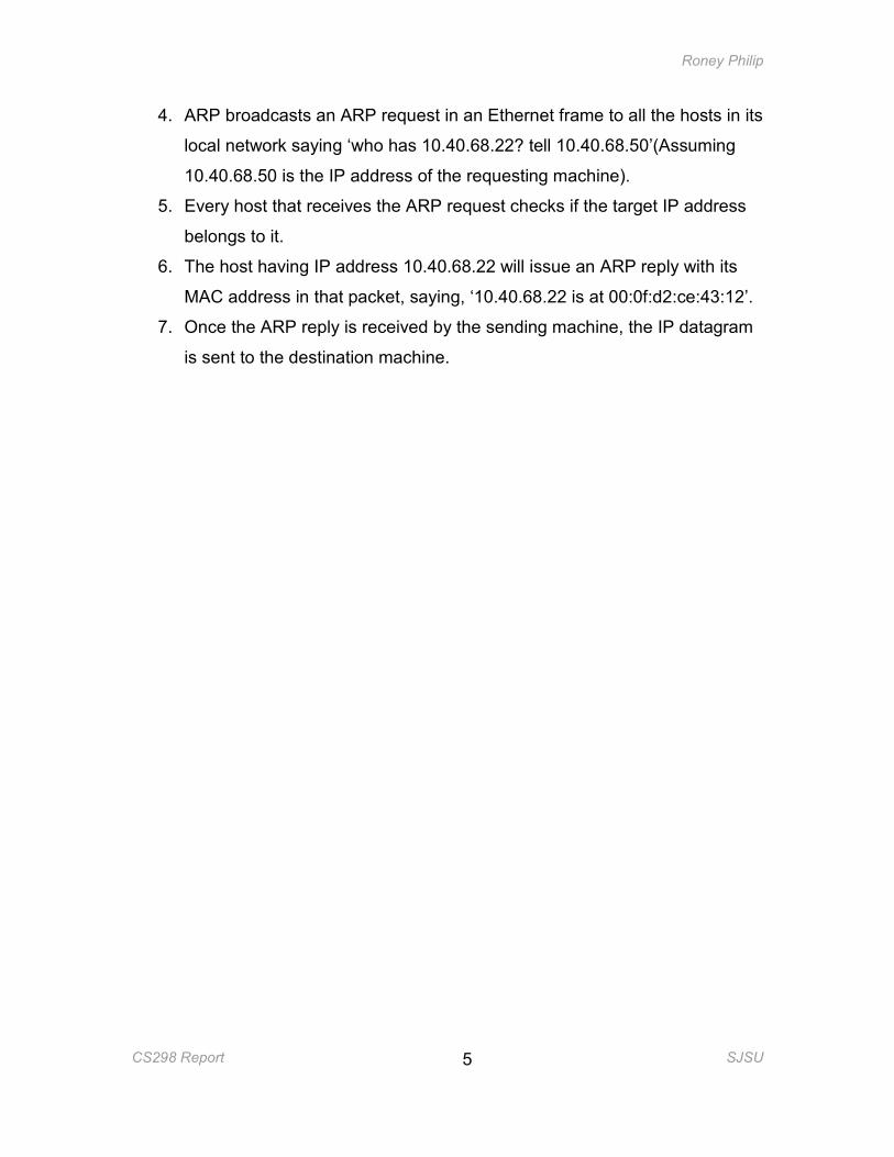
For example, suppose we type the command [13]
ftp 10.40.68.22
The following actions take place:
1. The FTP client asks the TCP layer to establish a connection with the IP
address specified in the command.
2. TCP sends a connection request segment to the destination IP address in
an IP datagram.
3. If the destination IP address is on a local network the IP address is
converted into a 48-bit Ethernet address via ARP.
Roney Philip
CS298 Report SJSU
5
4. ARP broadcasts an ARP request in an Ethernet frame to all the hosts in its
local network saying ‘who has 10.40.68.22? tell 10.40.68.50’(Assuming
10.40.68.50 is the IP address of the requesting machine).
5. Every host that receives the ARP request checks if the target IP address
belongs to it.
6. The host having IP address 10.40.68.22 will issue an ARP reply with its
MAC address in that packet, saying, ‘10.40.68.22 is at 00:0f:d2:ce:43:12’.
7. Once the ARP reply is received by the sending machine, the IP datagram
is sent to the destination machine.
Roney Philip
CS298 Report SJSU
6
ftp 10.40.68.22
(1) establish connection with IP address
(2) send IP datagram to destination IP address
(3) (4) (7) (5) (6) (5)
Figure 2: Operation of ARP when the command ftp 10.40.68.22 is typed
2.1.1 ARP Messages
There are four types of messages in the ARP protocol:
• ARP Request
FTP
TCP
IP
Ethernet driver
ARP
Ethernet driver
Ethernet driver
ARP IP ARP
TCP
Roney Philip
CS298 Report SJSU
7
• ARP Reply
• RARP Request
• RARP Reply
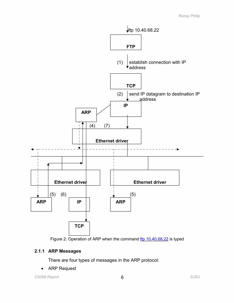
Figure 3: Format of an ARP message
The following are the fields of an ARP message:-
Hardware Type – Specifies what the underlying hardware is. Example,
Ethernet
Protocol type- Specifies the type of protocol above this layer
HLEN – Specifies the length of the hardware address
PLEN – Specifies the length of the Protocol (Example IP) address
Operation – Specifies what type of ARP message it is.
1 - ARP Request
2 - ARP Reply
3 – RARP Request4 – RARP Reply
Sender HA- Hardware Address/MAC address of the sending machine
Sender IP – IP address of the sending machine
Target IP – Target IP address of the destination machine
Target HA - Hardware Address/MAC address of the destination machine
• ARP Request – When a host sends an ARP request it fills in its MAC
address, IP address, type of ARP message and the target IP address. The
ARP request is broadcast to all the hosts in the same LAN as the sending
host. The target HA is left blank for the host with the target IP address to
fill in.
Roney Philip
CS298 Report SJSU
8
• ARP Reply – When a host receives an ARP request containing its own IP
address as the target IP address, it fills in the target HA field with its MAC
address. The host creates an ARP reply with the values of the sender and
target fields in the ARP request reversed and the Operation field set to the
opcode of the ARP reply. This packet is then sent only to the requesting
machine.
• RARP Request – Reverse Address Resolution Protocol (RARP) is the
reverse of ARP. A RARP request is sent when a machine wants to get the
IP address that corresponds to its MAC address. RARP requests are
broadcast in the LAN.
• RARP Reply – RARP Reply is sent by RARP servers. If the MAC address
in the RARP request belongs to one of the clients served by the RARP
server, a reply is sent with its corresponding IP address.
In this project we are not considering the RARP request and RARP reply
as these messages are sent to get the IP address of the requesting machine.
The ARP cache is not affected when RARP messages are sent or received.
Hence the ARP Cache Poisoning is not possible with RARP messages. Also,
most networks use the Dynamic Host Control Protocol (DHCP) or a static
configuration for IP address assignment; hence the usage of RARP is not
common.
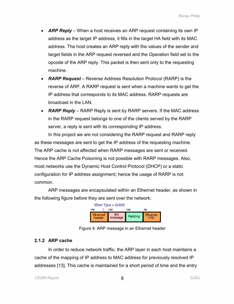
ARP messages are encapsulated within an Ethernet header, as shown in
the following figure before they are sent over the network.
Figure 4: ARP message in an Ethernet header
2.1.2 ARP cache
In order to reduce network traffic, the ARP layer in each host maintains a
cache of the mapping of IP address to MAC address for previously resolved IP
addresses [13]. This cache is maintained for a short period of time and the entry
Roney Philip
CS298 Report SJSU
9
is removed when its timeout expires; the timeout is renewed if it is accessed
again. An entry in the ARP cache is created or updated in the following cases:-
• Just before a host sends an ARP reply to the machine which sent the
ARP request, it will create an entry in its ARP cache for the mapping of
the sender’s IP address to the sender’s MAC address.
• Whenever a host receives an ARP request from another host, if an
entry corresponding to the IP address of the sending host exists in its
ARP cache, the entry will be updated.
2.2 ARP Cache Poisoning
ARP Cache Poisoning is the technique by which an attacker maliciously
modifies the mapping of an IP address to its corresponding MAC address in the
ARP cache of another host. This is a man-in-the-middle (MiM) attack by which
the attacker can divert the traffic passing between two machines to pass via him.
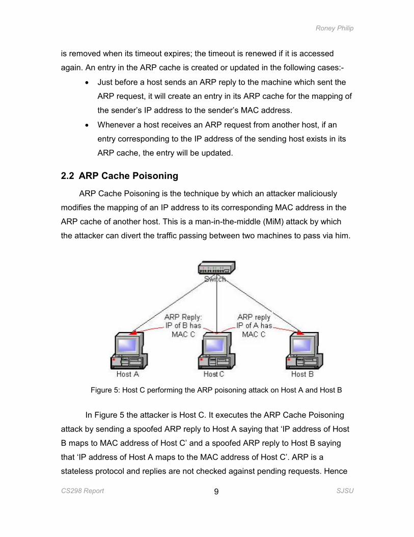
Figure 5: Host C performing the ARP poisoning attack on Host A and Host B
In Figure 5 the attacker is Host C. It executes the ARP Cache Poisoning
attack by sending a spoofed ARP reply to Host A saying that ‘IP address of Host
B maps to MAC address of Host C’ and a spoofed ARP reply to Host B saying
that ‘IP address of Host A maps to the MAC address of Host C’. ARP is a
stateless protocol and replies are not checked against pending requests. Hence
Roney Philip
CS298 Report SJSU
10
Host A and Host B will update their ARP cache with the mapping received in the
ARP replies.
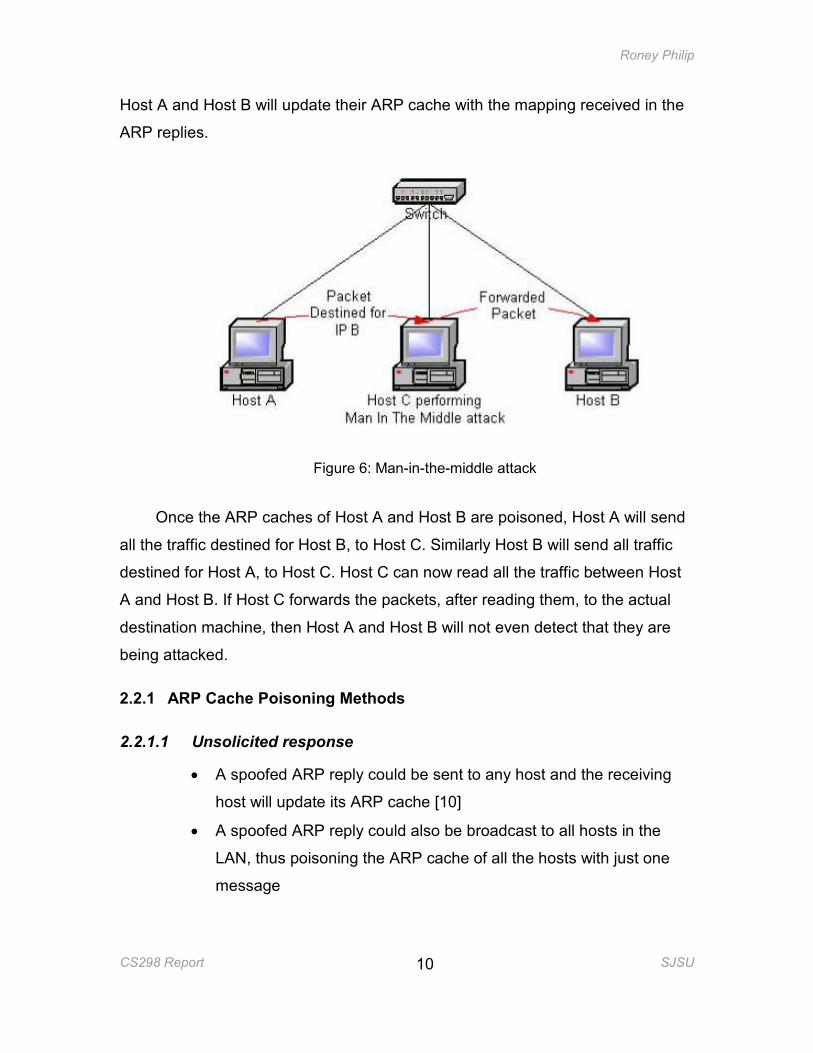
Figure 6: Man-in-the-middle attack
Once the ARP caches of Host A and Host B are poisoned, Host A will send
all the traffic destined for Host B, to Host C. Similarly Host B will send all traffic
destined for Host A, to Host C. Host C can now read all the traffic between Host
A and Host B. If Host C forwards the packets, after reading them, to the actual
destination machine, then Host A and Host B will not even detect that they are
being attacked.
2.2.1 ARP Cache Poisoning Methods
2.2.1.1 Unsolicited response
• A spoofed ARP reply could be sent to any host and the receiving
host will update its ARP cache [10]
• A spoofed ARP reply could also be broadcast to all hosts in the
LAN, thus poisoning the ARP cache of all the hosts with just one
message
Roney Philip
CS298 Report SJSU
11
2.2.1.2 Request
When a host receives an ARP request, the ARP layer in the host will
update its ARP cache with the mapping stated in the source IP and source MAC
address fields of the ARP request packet [10], even if the request was not for that
host. Hence an attacker only needs to send a spoofed ARP request (inherently
broadcasted) to poison the cache of all the hosts in a LAN.
2.2.1.3 Response to a request
A malicious host in a LAN, on receiving a legitimate ARP request, can
send a spoofed ARP reply [10]. There could be a race condition between the
spoofed ARP reply and the legitimate ARP reply in reaching the requesting host.
The ARP cache will be updated with the last received ARP reply.
2.3 Wireless networks
Wireless networks or Wireless LANs (WLANs) are LANs in which hosts
communicate via radio waves.
2.3.1 Modes of Wireless LANs
There are two modes of WLANs:-
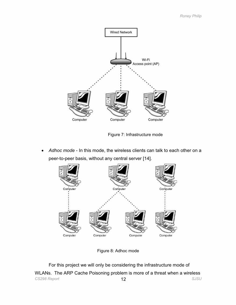
• Infrastructure mode – In this type of WLAN, all the wireless clients
communicate via a base station or an access point (AP). The access point
acts as a connection to the wired network, which is the backbone for the
WLAN [14].
Roney Philip
CS298 Report SJSU
12
Figure 7: Infrastructure mode
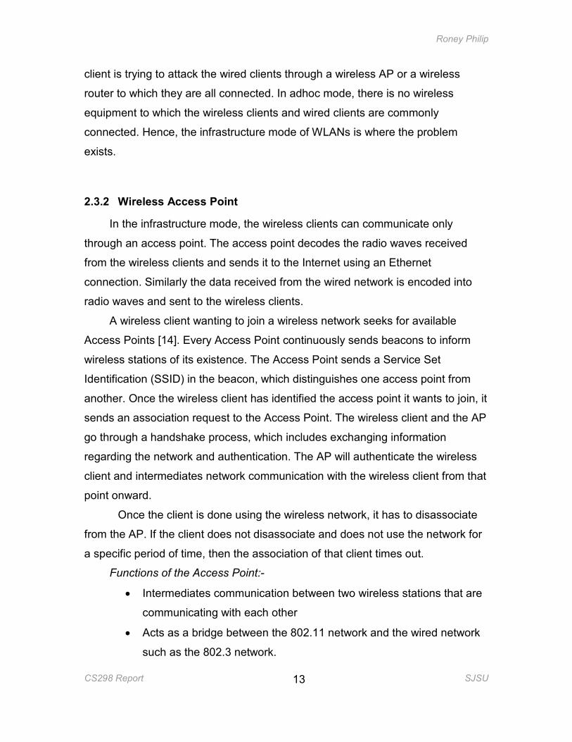
• Adhoc mode - In this mode, the wireless clients can talk to each other on a
peer-to-peer basis, without any central server [14].
Figure 8: Adhoc mode
For this project we will only be considering the infrastructure mode of
WLANs. The ARP Cache Poisoning problem is more of a threat when a wireless
Roney Philip
CS298 Report SJSU
13
client is trying to attack the wired clients through a wireless AP or a wireless
router to which they are all connected. In adhoc mode, there is no wireless
equipment to which the wireless clients and wired clients are commonly
connected. Hence, the infrastructure mode of WLANs is where the problem
exists.
2.3.2 Wireless Access Point
In the infrastructure mode, the wireless clients can communicate only
through an access point. The access point decodes the radio waves received
from the wireless clients and sends it to the Internet using an Ethernet
connection. Similarly the data received from the wired network is encoded into
radio waves and sent to the wireless clients.
A wireless client wanting to join a wireless network seeks for available
Access Points [14]. Every Access Point continuously sends beacons to inform
wireless stations of its existence. The Access Point sends a Service Set
Identification (SSID) in the beacon, which distinguishes one access point from
another. Once the wireless client has identified the access point it wants to join, it
sends an association request to the Access Point. The wireless client and the AP
go through a handshake process, which includes exchanging information
regarding the network and authentication. The AP will authenticate the wireless
client and intermediates network communication with the wireless client from that
point onward.
Once the client is done using the wireless network, it has to disassociate
from the AP. If the client does not disassociate and does not use the network for
a specific period of time, then the association of that client times out.
Functions of the Access Point:-
• Intermediates communication between two wireless stations that are
communicating with each other
• Acts as a bridge between the 802.11 network and the wired network
such as the 802.3 network.
Roney Philip
CS298 Report SJSU
14
2.4 ARP Cache Poisoning in Wireless Networks
ARP cache poisoning is an attack prevalent in LANs, i.e., all hosts
connected to the same switch or hub as that of a malicious host are vulnerable to
this attack. Access points act as hubs for wireless networks and act as bridges
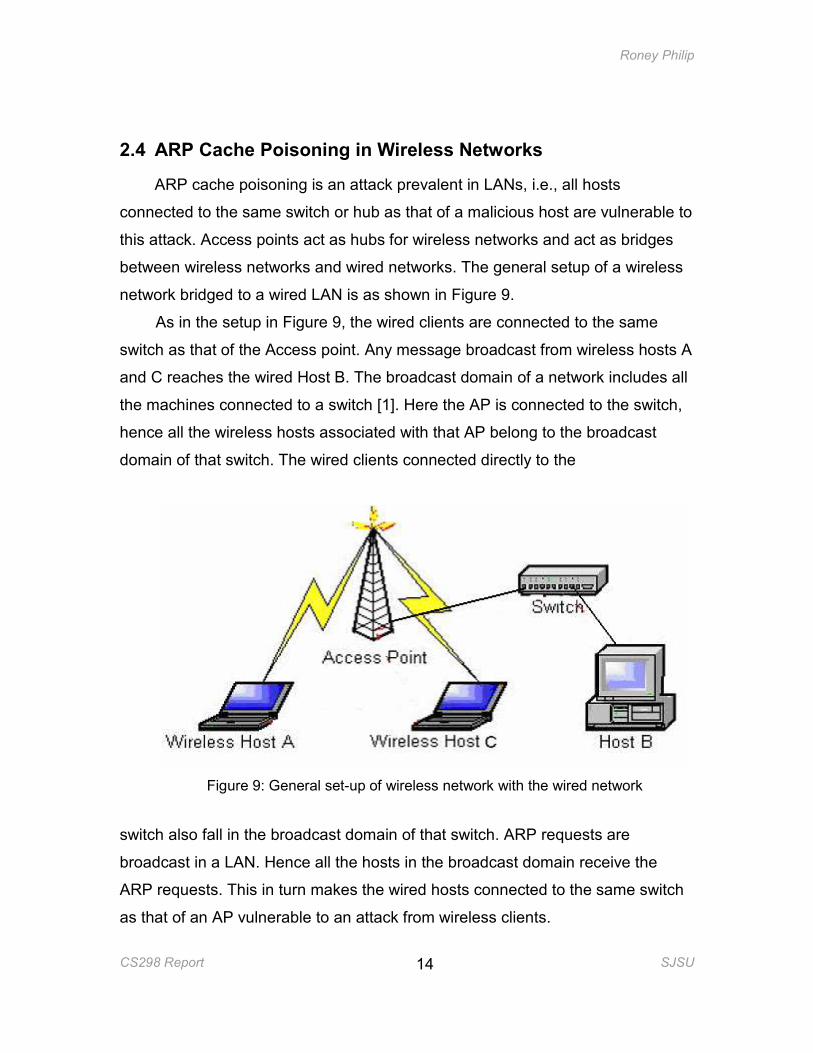
between wireless networks and wired networks. The general setup of a wireless
network bridged to a wired LAN is as shown in Figure 9.
As in the setup in Figure 9, the wired clients are connected to the same
switch as that of the Access point. Any message broadcast from wireless hosts A
and C reaches the wired Host B. The broadcast domain of a network includes all
the machines connected to a switch [1]. Here the AP is connected to the switch,
hence all the wireless hosts associated with that AP belong to the broadcast
domain of that switch. The wired clients connected directly to the
Figure 9: General set-up of wireless network with the wired network
switch also fall in the broadcast domain of that switch. ARP requests are
broadcast in a LAN. Hence all the hosts in the broadcast domain receive the
ARP requests. This in turn makes the wired hosts connected to the same switch
as that of an AP vulnerable to an attack from wireless clients.
Roney Philip
CS298 Report SJSU
15
Generally, in hot spots like cafes, car dealerships etc., an Access Point will
be provided to customers who have a wireless host so as to get connected to the
wireless network. The general setup is such that the AP will be connected to a
switch to which the café’s wired hosts are also connected. The wired hosts could
be transmitting confidential information among each other. This information can
be easily read if a malicious wireless customer does a MiM attack using ARP
Cache Poisoning.
The ARP cache poisoning attack can be performed even if the wireless
clients are in a wireless network enabled with security features like Wired
Equivalent Privacy (WEP) or Wi-Fi Protected Access (WPA). WEP and WPA
encrypt the Layer 2 packets. ARP, being in the same layer as IP, is a Layer 3
protocol. Hence the poisoned ARP packets sent in a wireless network are sent
within a WEP or WPA encrypted frame. The wireless clients that are doing the
ARP cache poisoning attack have already joined the network and hence all
packets sent from these wireless clients are encrypted. The Access Point will
accept and forward these packets to the destination wireless machine because
they are WEP or WPA encrypted with the initially assigned key. When the packet
reaches the destination machine the frame is decrypted and the spoofed
mapping is read from the ARP frame. The ARP cache is updated with the
spoofed mapping, thus poisoning the ARP cache.
2.4.1 Attack Scenarios
2.4.1.1 Attacking wired clients using a wireless client
Roney Philip
CS298 Report SJSU
16
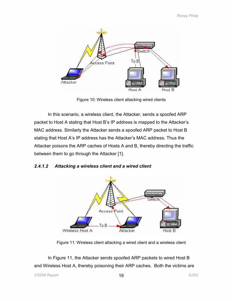
Figure 10: Wireless client attacking wired clients
In this scenario, a wireless client, the Attacker, sends a spoofed ARP
packet to Host A stating that Host B’s IP address is mapped to the Attacker’s
MAC address. Similarly the Attacker sends a spoofed ARP packet to Host B
stating that Host A’s IP address has the Attacker’s MAC address. Thus the
Attacker poisons the ARP caches of Hosts A and B, thereby directing the traffic
between them to go through the Attacker [1].
2.4.1.2 Attacking a wireless client and a wired client
Figure 11: Wireless client attacking a wired client and a wireless client
In Figure 11, the Attacker sends spoofed ARP packets to wired Host B
and Wireless Host A, thereby poisoning their ARP caches. Both the victims are
Roney Philip
CS298 Report SJSU
17
in the same broadcast domain as that of the Attacker, hence spoofed ARP
packets will reach the victims [1].
2.4.1.3 Attacking wireless hosts
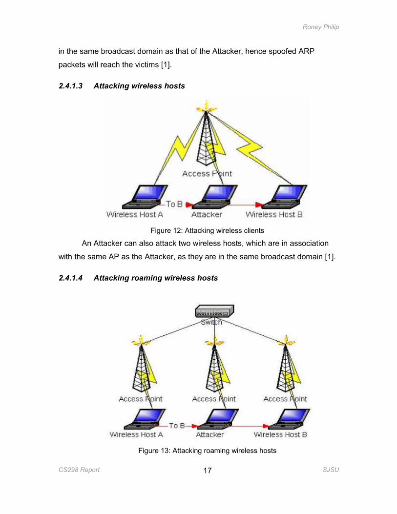
Figure 12: Attacking wireless clients
An Attacker can also attack two wireless hosts, which are in association
with the same AP as the Attacker, as they are in the same broadcast domain [1].
2.4.1.4 Attacking roaming wireless hosts
Figure 13: Attacking roaming wireless hosts
Roney Philip
CS298 Report SJSU
18
In Figure 13, there are multiple APs connected to the same switch. In
802.11b networks, to achieve roaming, the APs need to be connected to the
same switch [1]. Due to this set up all the wireless hosts associated with these
APs belong in the same broadcast domain. Hence any forged ARP packet sent
from the Attacker can reach any wireless host connected to any of these APs.
2.4.1.5 Attacking home networks
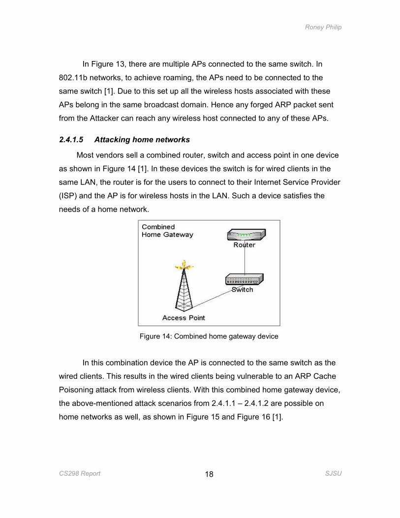
Most vendors sell a combined router, switch and access point in one device
as shown in Figure 14 [1]. In these devices the switch is for wired clients in the
same LAN, the router is for the users to connect to their Internet Service Provider
(ISP) and the AP is for wireless hosts in the LAN. Such a device satisfies the
needs of a home network.
Figure 14: Combined home gateway device
In this combination device the AP is connected to the same switch as the
wired clients. This results in the wired clients being vulnerable to an ARP Cache
Poisoning attack from wireless clients. With this combined home gateway device,
the above-mentioned attack scenarios from 2.4.1.1 – 2.4.1.2 are possible on
home networks as well, as shown in Figure 15 and Figure 16 [1].
Roney Philip
CS298 Report SJSU
19
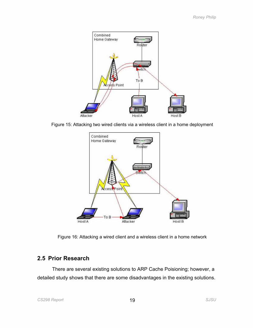
Figure 15: Attacking two wired clients via a wireless client in a home deployment
Figure 16: Attacking a wired client and a wireless client in a home network
2.5 Prior Research
There are several existing solutions to ARP Cache Poisioning; however, a
detailed study shows that there are some disadvantages in the existing solutions.
Roney Philip
CS298 Report SJSU
20
Issac, B. et al [2] proposes ‘Secure Unicast ARP by extending DHCP’ to
prevent ARP cache poisoning. In this solution, when Host A wants to
communicate with Host B, it first sends a secure unicast ARP request packet to a
DHCP+ server. A Secure Unicast ARP (S-UARP) request packet is a unicast
ARP request packet sent to a DHCP+ server. The DHCP+ server is an enhanced
DHCP server that understands Secure Unicast ARP packet formats. The DHCP+
server has information about the IP and MAC address mapping of all the hosts to
which it has leased an IP address. Hence it responds with the MAC address
mapped to the requested IP address in an encrypted format. It is a trusted party
and the messages are encrypted before transmission, with a secret key that has
been distributed to the client and the server by a Certification Authority. This
makes sure that Host A will not get an ARP packet, which could cause poisoning.
The drawback of this solution is that it requires modification to the ARP protocol,
which means that all the Hosts in a LAN that want to prevent ARP Cache
poisoning would have to modify their kernels to reflect the modified ARP protocol.
It would also require a DHCP+ server, which would understand the secure
unicast ARP packet and respond to it. Another modification that would be
required is to the DHCP relay agent, as it has to be able to identify an S-UARP
packet and forward it to the DHCP+ server.
Brushi et al [9] has proposed a Secure ARP (S-ARP), which uses
asymmetric key cryptography to authenticate the hosts in a LAN. A Certification
Authority assigns a private/public key pair to every host in the LAN. Each ARP
packet sent from a host is signed with the host’s private key. The receiving host
verifies the signature of the ARP packet using the sending host’s public key. To
include the signature of the sending host in the ARP packet, an additional header
is inserted at the end of the standard ARP protocol header. The solution in [9]
also requires modification to the ARP protocol as the sender needs to sign each
ARP message with his private key and the receiving host needs to verify the
signature with the sender’s public key. The author mentions in [9] that to get the
entire LAN completely secure, all the hosts should be S-ARP enabled. S-ARP
also introduces additional overhead and time for signature and verification by the
Roney Philip
CS298 Report SJSU
21
sender and the receiver respectively, for each ARP message. The other issue
with this solution is that this is not a feasible approach for a wireless network
environment like a hotspot, where the wireless clients entering the network are
random and short-time users who cannot be expected to have S-ARP enabled.
Tripunithara, et al proposed a Middleware approach to prevent ARP cache
poisoning in [10]. This approach maintains a ‘requested’ queue and a
‘responded’ queue in each host. If the host has sent an ARP request, it will be
entered in the ‘requested’ queue and when the corresponding reply is received, it
is entered in the ‘responded’ queue. Hence, whenever an ARP response is
received, it is allowed to update the ARP cache only if there is a corresponding
request in its request queue. The solution prevents the ARP Cache Poisoning
attacks, but each and every host in the LAN has to be modified. The scale of
deployment is very high.
3. DESIGN
3.1 Design goals
3.1.1 Protocol should remain unmodified
One of the major design goals for my project was that the ARP protocol
itself should not require any modification. ARP protocol, as part of the TCP/IP
suite, is a very popularly used protocol for mapping a host’s IP address to its
MAC address. The TCP/IP suite is widely deployed. Hence any protocol changes
would require modification in all the hosts that need to use the protocol. In our
design only the access point needs to be modified, hence the scale of
deployment is much less compared to having to deploy the modification in all the
hosts in a LAN.
3.1.2 Transparent to the users
The other design goal was to ensure that the security added to this protocol
would be transparent to the users. For example, the user would not have to
create any password or key to enable security from these attacks. By our design
Roney Philip
CS298 Report SJSU
22
the wireless clients just need to send ARP packets to the Access Point in the
usual manner and it is the responsibility of the Access Point to monitor the
packets for ARP Cache Poisoning attacks and make sure that the wireless
clients are secure.
3.1.3 Minimal overhead when sending and receiving ARP packets
One of the other design goals was to make sure that there is minimal
overhead in terms of expensive operations, associated with sending and
receiving an ARP packet. For example, the sending host should not have to sign
each ARP packet and the receiving host should not have to verify each ARP
packet received using the public key of the sending host. These expensive
operations would result in increasing the round-trip time of an ARP response
being received, which ultimately affects the round trip time of the upper layer
protocols.
3.2 The Design
3.2.1 Wireless clients and DHCP
In order for a wireless client to communicate via the wireless card, it has to
associate with an Access Point. Once the wireless client associates with the
Access Point, it has to get an IP address in order for it to connect to clients
outside its LAN or to the Internet. In most networks today, the wireless client gets
an IP address for itself from a DHCP (Dynamic Host Control Protocol) server.
This is accomplished by sending a DHCP request; the DHCP protocol is
explained in the next section.
3.2.2 DHCP Protocol
The DHCP protocol is a way of providing host-specific configuration
parameters as well as providing network/IP addresses to the hosts from a DHCP
server.
For the rest of our discussion we are only interested in the function of DHCP
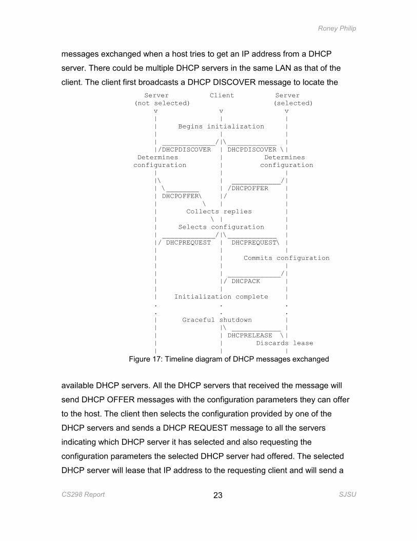
in providing IP addresses to the hosts. Figure 17 shows the timeline diagram of
Roney Philip
CS298 Report SJSU
23
messages exchanged when a host tries to get an IP address from a DHCP
server. There could be multiple DHCP servers in the same LAN as that of the
client. The client first broadcasts a DHCP DISCOVER message to locate the
Server Client Server (not selected) (selected) v v v | | | | Begins initialization | | | | | _____________/|\____________ | |/DHCPDISCOVER | DHCPDISCOVER \| Determines | Determines configuration | configuration | | | |\ | ____________/| | \________ | /DHCPOFFER | | DHCPOFFER\ |/ | | \ | | | Collects replies | | \ | | | Selects configuration | | _____________/|\____________ | |/ DHCPREQUEST | DHCPREQUEST\ | | | | | | Commits configuration | | | | | _____________/| | |/ DHCPACK | | | | | Initialization complete | . . . . . . | Graceful shutdown | | |\ ____________ | | | DHCPRELEASE \| | | Discards lease | | |
Figure 17: Timeline diagram of DHCP messages exchanged
available DHCP servers. All the DHCP servers that received the message will
send DHCP OFFER messages with the configuration parameters they can offer
to the host. The client then selects the configuration provided by one of the
DHCP servers and sends a DHCP REQUEST message to all the servers
indicating which DHCP server it has selected and also requesting the
configuration parameters the selected DHCP server had offered. The selected
DHCP server will lease that IP address to the requesting client and will send a
Roney Philip
CS298 Report SJSU
24
DHCP ACK message as a confirmation to the client. The IP address given to the
client will not be given to any other host till the lease period is over.
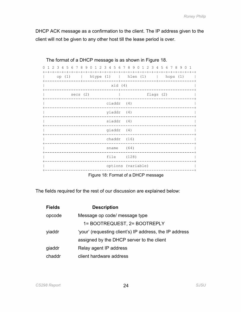
The format of a DHCP message is as shown in Figure 18.
0 1 2 3 4 5 6 7 8 9 0 1 2 3 4 5 6 7 8 9 0 1 2 3 4 5 6 7 8 9 0 1 +-+-+-+-+-+-+-+-+-+-+-+-+-+-+-+-+-+-+-+-+-+-+-+-+-+-+-+-+-+-+-+-+ | op (1) | htype (1) | hlen (1) | hops (1) | +---------------+---------------+---------------+---------------+ | xid (4) | +-------------------------------+-------------------------------+ | secs (2) | flags (2) | +-------------------------------+-------------------------------+ | ciaddr (4) | +---------------------------------------------------------------+ | yiaddr (4) | +---------------------------------------------------------------+ | siaddr (4) | +---------------------------------------------------------------+ | giaddr (4) | +---------------------------------------------------------------+ | chaddr (16) | +---------------------------------------------------------------+ | sname (64) | +---------------------------------------------------------------+ | file (128) | +---------------------------------------------------------------+ | options (variable) | +---------------------------------------------------------------+
Figure 18: Format of a DHCP message
The fields required for the rest of our discussion are explained below:
Fields Description
opcode Message op code/ message type
1= BOOTREQUEST, 2= BOOTREPLY
yiaddr ‘your’ (requesting client’s) IP address, the IP address
assigned by the DHCP server to the client
giaddr Relay agent IP address
chaddr client hardware address
Roney Philip
CS298 Report SJSU
25
The format of the DHCP message remains the same for all the message
types discussed above. But with each iteration the fields in the DHCP message
get filled progressively. The ‘opcode’ indicates the type of DHCP message.
During the DHCP DISCOVER – DHCP REQUEST message iterations the
‘yiaddr’ field is not filled. In the DHCP ACK message the IP address assigned to
the client is put in this field. In the DHCP ACK message all the fields of the DHCP
message are filled. The ‘giaddr’ is the default gateway address, to which the
client sends packets destined for machines outside its LAN. The ‘chaddr’ field
contains the MAC address of the requesting client machine.
As the DHCP server and the DHCP messages contain the original IP
address and MAC address of all the DHCP-enabled machines in a LAN, the
Access Point can get the IP-to-MAC address mapping directly from the DHCP
server or build up the mapping by monitoring DHCP messages. It can use this
information to verify future ARP packets that are passing through it. This leads to
the following alternatives:-
• Design using the DHCP leases file
• Design using the DHCP ACK message
3.2.3 Design using the DHCP leases file
In most Access Points the DHCP Server exists within the Access Point
itself. In that case the DHCP server will store all the IP addresses that it has
leased out within that network along with their MAC addresses, retrieved from the
DHCP messages, in the dhcp.leases file. This file will include all the wired clients
connected to the switch within the Access Point and all the wireless clients
associated with the Access Point. Whenever the Access Point sees an ARP
request or reply, it can check the dhcp.leases file to verify whether the mapping
in the ARP request/reply corresponds to the one in the file. If the mapping is not
valid, the ARP request/reply packet can be choked. This prevents the ARP
request/reply from poisoning the ARP cache of all the hosts connected to the
Access Point as well as preventing the spoofed ARP packet from reaching the
wired network.
Roney Philip
CS298 Report SJSU
26
3.2.4 Design using the DHCP ACK message
In a wireless network, since all the wireless clients can only communicate
through the Access Point, every packet generated by or destined for a wireless
client first reaches the Access Point. Hence, when a wireless client requests an
IP address from the DHCP server, the DHCP messages are first received by the
Access Point. The Access Point creates a mapping table, which stores the
mapping of IP addresses to MAC addresses. The DHCP ACK message contains
the client’s MAC address and IP address. Every packet that reaches the Access
Point should be scanned for a DHCP ACK message. Whenever a DHCP ACK
message is encountered the IP address to MAC address mapping should be
retrieved and stored in a mapping table created by the Access Point to store IP
address to MAC address mappings. Since all the wireless clients registered with
the Access Point have to get an IP address using the DHCP protocol, the
mapping table will contain the correct mapping of all the wireless clients that
communicate through this Access Point. Now, whenever the Access Point sees
an ARP request or reply, it can use its mapping table to verify whether the
mapping in the ARP request/reply is valid. If the mapping is not valid, the ARP
request/reply packet can be choked. This prevents the ARP request/reply from
poisoning the ARP cache of all the hosts connected to the Access Point as well
as preventing the spoofed ARP packet from reaching the wired network.
3.2.5 Components of the system
3.2.5.1 Mapping table
The Access Point creates a hash table with IP address as the key and a
structure containing the MAC address and the time of expiry (the time of expiry is
calculated by retrieving the lease time and calculating the Access Point’s time at
the end of the lease time) as the value. Keeping the IP address as the key
ensures that there are no duplicate IP addresses and each IP address maps to
only one MAC address. Whenever an attacker spoofs an ARP message, he will
be mapping a victim’s IP address to his MAC address. Since an entry already
exists in the mapping table containing the victim’s IP address mapped to the
Roney Philip
CS298 Report SJSU
27
victim’s MAC address, this message will be detected as an ARP poisoning
packet.
This mapping table can be derived from the dhcp.leases file in an Access
Point with a DHCP server running within it.
3.2.5.2 DHCP Agent
The DHCP agent scans all the incoming traffic, searching for a DHCP ACK
message. Whenever the DHCP ACK message is encountered, the DHCP Agent
will retrieve the values of the fields ‘yiaddr’ and ‘chaddr’ and store them as a new
entry or overwrite the IP address and MAC address columns of an existing entry
in the mapping table. There are two ways by which the mapping table is updated:
Case 1: New entry in the mapping table
A new entry is created in the mapping table when the DHCP server is
assigning an IP address to the requesting client for the first time.
Case 2: Overwrite an existing entry
This happens when the DHCP server is extending the lease of an IP
address previously assigned to the requesting client.
If the DHCP server exists within the Access Point, the DHCP server does
the dhcp agent’s work and the mappings are stored in the dhcp.leases file.
3.2.5.3 ARP Patrol Agent
The ARP Patrol Agent monitors all incoming traffic, looking for ARP
messages. Irrespective of whether the ARP message is a request or reply, the
mapping of the source IP to source MAC address is verified with the entries in
the mapping table or the dhcp.leases file. We only check the source IP and the
source MAC address mapping because, whether it’s an ARP reply or request,
the attacker is trying to spoof the source addresses since the receiving machine
updates its ARP cache using the values in the source address fields. If the
mapping is not valid, the ARP packet is choked.
Roney Philip
CS298 Report SJSU
28
3.3 Algorithm
3.3.1 DHCP agent algorithm
The algorithm for the DHCP agent is as follows:
Whenever a DHCP frame is received:
If the field, ‘Message type’ in the DHCP packet is Boot reply
If the ‘DHCP Message Type’ is DHCP ACK
Retrieve the IP address from the field ‘yiaddr’ and search
for it in the mapping table
If the yiaddr does not exist,
Add it as a new entry into the mapping table.
Retrieve the MAC address from the field ‘chaddr’
and add it as a value corresponding to the previously
entered key.
Else,
Retrieve the MAC address from the field ‘chaddr’
and update the value corresponding to the retrieved
key
Else,
Do nothing
Else,
Do nothing
3.3.2 ARP Patrol agent algorithm
The algorithm for the ARP Patrol agent is as follows
When an ARP frame is received:
If source IP address in the packet is an entry in the DHCP hash table or
dhcp.leases file and the expiry time has not passed
Roney Philip
CS298 Report SJSU
29
If the MAC address corresponding to the IP address in the
hash table or dhcp.leases file is the same as the source MAC
address in the packet
Accept the packet
Else,
Drop the packet (Do not let the packet be sent to the
destination machine)
Else,
If the expiry time has passed
Remove the entry in the mapping table and drop the ARP
packet
Else,
this ARP packet is accepted.
This algorithm protects all machines within a network, which have received
their IP addresses via the DHCP protocol, from ARP cache poisoning. An
attacker trying to perform an ARP cache poisoning attack will be spoofing the
source IP address in the ARP packet with the victim’s IP address and the source
MAC address with the attacker’s own MAC address. If the victim has received
the IP address via the DHCP protocol, the IP address to MAC address mapping
of the victim machine would be in the DHCP mapping table or the dhcp.leases
file. When the ARP patrol agent receives the spoofed ARP packet from the
attacker, the attack is immediately detected and packet is dropped.
4. IMPLEMENTATION
This section explains how the design described above was implemented in
a real world wireless Access Point. It first describes the choices available in
hardware and the one that was chosen for this project. This section also
describes in detail the ‘open source firmware’ that was chosen to be uploaded
into the hardware in order to make the modifications.
Roney Philip
CS298 Report SJSU
30
4.1 Hardware
The choice of hardware was based on which manufacturers were providing
source code for their firmware. The two open source wireless Access Points that
I explored were EW-7209APg manufactured by Edimax and WRT54GL
manufactured by Linksys.
4.1.1 EW7209APg by Edimax
The EW7209APg is a wireless Access Point that complies with the IEEE
802.11b/g 2.4 GHz specification along with a built-in 5-port 10/100 M switch. The
hardware also provides a DHCP server within it. One of the advantages of this
hardware is that the firmware is upgradeable via a web server. The problem
encountered with this hardware was that all the necessary tools and other
support needed for correctly building the source code were not available. The
build scripts were not complete and this resulted in the developer-compiled
firmware not being usable to upgrade the hardware.
4.1.2 WRT54GL by Linksys
WRT54GL is a Wi-Fi enabled router manufactured by Linksys, through
which wireless and wired clients can share an Internet connection using the
802.3 Ethernet and 802.11b/g data link layers. WRT54GL combines the
functionality of an Ethernet switch, wireless access point and a router. The
wireless access point serves wireless clients and the Ethernet switch connects
the wired clients. The router connects all of the wired and wireless clients via a
DSL connection or a high-speed cable to the Internet. The wireless router also
acts as a DHCP server to all the clients connected to the wireless access point
and the Ethernet switch.
Roney Philip
CS298 Report SJSU
31
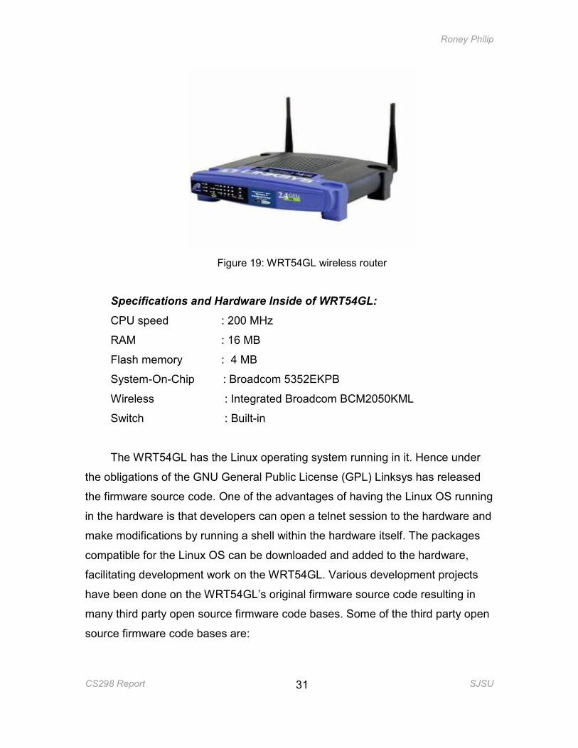
Figure 19: WRT54GL wireless router
Specifications and Hardware Inside of WRT54GL:
CPU speed : 200 MHz
RAM : 16 MB
Flash memory : 4 MB
System-On-Chip : Broadcom 5352EKPB
Wireless : Integrated Broadcom BCM2050KML
Switch : Built-in
The WRT54GL has the Linux operating system running in it. Hence under
the obligations of the GNU General Public License (GPL) Linksys has released
the firmware source code. One of the advantages of having the Linux OS running
in the hardware is that developers can open a telnet session to the hardware and
make modifications by running a shell within the hardware itself. The packages
compatible for the Linux OS can be downloaded and added to the hardware,
facilitating development work on the WRT54GL. Various development projects
have been done on the WRT54GL’s original firmware source code resulting in
many third party open source firmware code bases. Some of the third party open
source firmware code bases are:
Roney Philip
CS298 Report SJSU
32
• DDWrt – DDWrt is a third party firmware developed from the existing Linux
source code in the WRT5GL Linksys router. The firmware adds more
features to the original router code. This firmware is mainly used for
increasing the functionality of the router and customizing it. It is not
intended for open source development although the source code is
available.
• OpenWrt – OpenWrt is a third party firmware developed from scratch
using the stock firmware of the WRT54GL wireless router. It is intended
for developers to be able to add features and publish them to the OpenWrt
community of developers.
4.2 OpenWrt Firmware
For this project I chose OpenWrt.
4.2.1 About OpenWrt
OpenWrt is a Linux distribution, which has its own writable file system and
package management system [6]. It contains more than 100 software packages
and provides facilities in the source code to include more add-on packages. The
OpenWrt source code is oriented towards developers by providing a build
system, which enables developers to modify the firmware by changing the source
code.
4.2.2 Compiling source code for embedded systems
Source code for embedded systems cannot be compiled within the
embedded system itself. Embedded systems have lower processing power and
memory; hence it is not possible to run a compiler directly on an embedded
system. Instead, we need to have a cross compiler on our development machine
that will compile the firmware and produce the binary for our embedded system.
4.2.3 Building OpenWrt image
OpenWrt’s build script has been made easy for developers to download the
source code and build the firmware image [6]. OpenWrt’s Makefiles are written in
Roney Philip
CS298 Report SJSU
33
such a way that they will download the sources, apply necessary patches to work
with the given platform and compile the source code for the given platform. The
developer does not need to download the appropriate cross-compiler or the
patches for the kernel or any other packages necessary for the source code to be
compiled since the Makefiles will do it automatically if necessary.
One of the challenges I faced was to understand the design and
implementation details of the source code. In addition to the Linux kernel, there
are also several packages/modules specific to the router and the OpenWrt
distribution. There’s very little, if any, documentation on the design and code
details. It was also necessary to understand how the Makefiles are structured in
OpenWrt, so that upon making changes to parts of the source code tree, those
parts would actually get built with the changes and not get regenerated from the
original source.
4.3 Code placement
One of the coding-level challenges in this project was to find the appropriate
location to hook the arp_patrol_agent() code. As the DHCP server was already in
the system, I followed the ‘Design using dhcp.leases file’ approach, thus not
needing to implement the dhcp_agent () in this hardware. The arp_patrol_agent()
needed to be placed in such a location where I could monitor packets
irrespective of whether they are sent by a wireless client or a wired client.
There exists a framework called Netfilter for doing packet filtering/mangling
at the kernel level. Different layers in the network stack provide network hooks.
Hooks are specific locations in the code to which software can register itself.
Kernel modules that want to mangle packets should register with these netfilter
hooks. Whenever the code reaches the netfilter hooks, the kernel modules that
have registered with these hooks will be invoked.
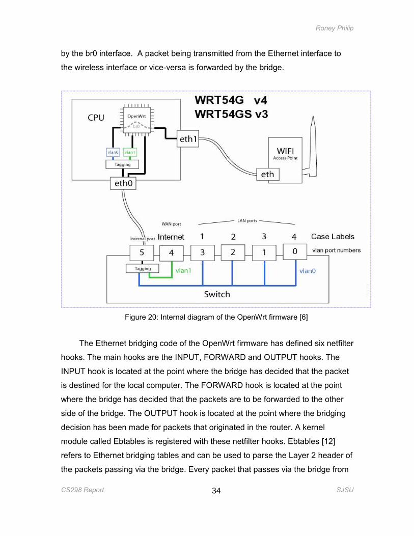
As shown in Fig 20, in the OpenWrt firmware, the wired Ethernet interface
(vlan0) and the wireless interface (eth1) are connected by a bridge, represented
Roney Philip
CS298 Report SJSU
34
by the br0 interface. A packet being transmitted from the Ethernet interface to
the wireless interface or vice-versa is forwarded by the bridge.
Figure 20: Internal diagram of the OpenWrt firmware [6]
The Ethernet bridging code of the OpenWrt firmware has defined six netfilter
hooks. The main hooks are the INPUT, FORWARD and OUTPUT hooks. The
INPUT hook is located at the point where the bridge has decided that the packet
is destined for the local computer. The FORWARD hook is located at the point
where the bridge has decided that the packets are to be forwarded to the other
side of the bridge. The OUTPUT hook is located at the point where the bridging
decision has been made for packets that originated in the router. A kernel
module called Ebtables is registered with these netfilter hooks. Ebtables [12]
refers to Ethernet bridging tables and can be used to parse the Layer 2 header of
the packets passing via the bridge. Every packet that passes via the bridge from
Roney Philip
CS298 Report SJSU
35
one Layer 2 interface to another Layer 2 interface has to pass through the
netfilter FORWARD hook, which will invoke the ebtables module. This parsing of
packets by Ebtables is not done by default. As part of my implementation, I force
the Ebtables module to parse the Layer 2 header of every packet passing via the
bridge. When an ARP packet is detected, Ebtables invokes the ebt_arp_filter()
function. In this function I have added my arp_patrol_agent() hook. The
arp_patrol_agent detects the occurrence of an ARP poisoning attack. Depending
on the verdict from the arp_patrol_agent() the ebt_arp_filter() function is asked to
DROP or ACCEPT the packet .
4.4 Implementation details
This section describes the implementation details of the various components
of the system.
4.4.1 dhcp.leases file
The DHCP server in the router assigns IP addresses to wireless clients and
wired clients that are connected to the router. For every IP address assigned the
server stores the IP address and the MAC address of the machine to which the
IP address is assigned, in a dhcp.leases file. The fully qualified path of the file in
this firmware is /tmp/dhcp.leases
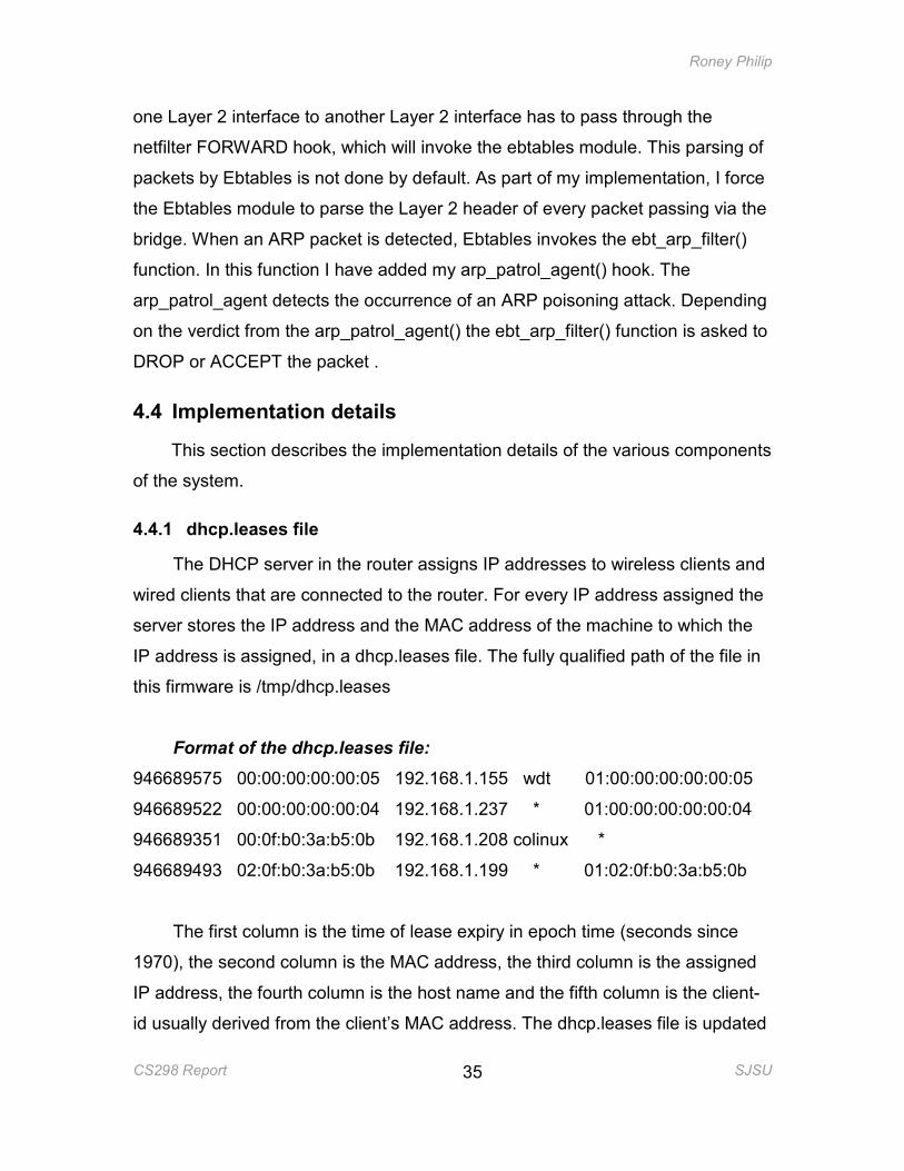
Format of the dhcp.leases file:
946689575 00:00:00:00:00:05 192.168.1.155 wdt 01:00:00:00:00:00:05
946689522 00:00:00:00:00:04 192.168.1.237 * 01:00:00:00:00:00:04
946689351 00:0f:b0:3a:b5:0b 192.168.1.208 colinux *
946689493 02:0f:b0:3a:b5:0b 192.168.1.199 * 01:02:0f:b0:3a:b5:0b
The first column is the time of lease expiry in epoch time (seconds since
1970), the second column is the MAC address, the third column is the assigned
IP address, the fourth column is the host name and the fifth column is the client-
id usually derived from the client’s MAC address. The dhcp.leases file is updated
Roney Philip
CS298 Report SJSU
36
every time an IP address is assigned newly or when a client renews the lease
time for a previously assigned IP address. The entry is removed when the lease
expires. Hence the dhcp.leases file is always up to date.
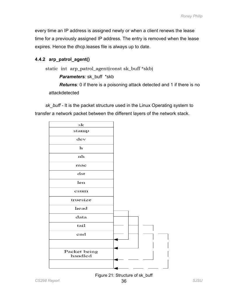
4.4.2 arp_patrol_agent()
static int arp_patrol_agent(const sk_buff *skb)
Parameters: sk_buff *skb
Returns: 0 if there is a poisoning attack detected and 1 if there is no
attackdetected
sk_buff - It is the packet structure used in the Linux Operating system to
transfer a network packet between the different layers of the network stack.
Figure 21: Structure of sk_buff
Roney Philip
CS298 Report SJSU
37
Once a packet is received at the physical layer, which is the NIC, the device
driver creates an sk_buff structure and populates it with IP data [11]. The device
driver then calls the function netif_rx() to pass the sk_buff structure to the upper
layer protocols.
Description of the important fields follows:
sk: pointer to the socket owning this packet
stamp: time this packet arrived
h: transport layer header pointer
nh: network layer header
mac: pointer to link layer header
len: actual data length
next: pointer to the next sk_buff{}
prev: pointer to the previous sk_buff{}
dev: dev currently being used
data: pointer to the start of data.
tail: pointer to end of protocol data.
end: pointer to end of the buffer holding
The sk_buff structure has a pointer nh, to the network layer header; in the
case of an ARP packet the network layer header is the ARP header. From the
ARP header, the function will read the source IP address and check if that IP
address exists in the dhcp.leases file. If so, the function will retrieve the source
MAC address from the sk_buff structure and compare it with the one in the
dhcp.leases file, corresponding to the source IP address. If the mapping in the
packet is not the same as the mapping in the dhcp.leases file a value of 0 is
returned, else a value of 1 is returned. If the IP address in the sk_buff structure
does not exist in the dhcp.leases file, a value of 1 is returned.
Roney Philip
CS298 Report SJSU
38
4.4.3 Boot script changes
The kernel module, Ebtables, into which I hooked my arp_patrol_agent,
does not get loaded into the kernel by default at boot time. The user can start an
ssh or a telnet session with the router and type insmod (insert module) on the
command line to get Ebtables and other related modules to be loaded. In order to
automate the process of ARP cache poisoning detection, I’ve modified an
OpenWrt boot script to insert the necessary modules at boot time.
When the OpenWrt distribution of the Linux Operating system boots up, it
runs all the boot scripts starting with the letter ‘S’ in the /etc/init.d directory. The
daemons and background processes that need to be run when the system is
booting up are included in these scripts. One such boot script is the ‘S10boot’
script. I have added the commands to insert the modules ebtables, ebt_arp and
ebtable_filter in this boot script.
4.4.4 Limitation of this implementation
The WRT54GL router uses a Broadcom chipset in its wireless Access Point.
Broadcom does not release the device driver source code that handles the
transmission of packets from one wireless client to another wireless client. The
arp_patrol_agent() needs only to be hooked into the device driver code for the
ARP cache poisoning attack to be prevented from one wireless client to another
wireless client. But since the source code is not available, the agent has currently
not been hooked into the driver.
5. TEST CASES AND RESULTS
This section describes the various tests done to poison a host’s ARP cache,
emulating various attack scenarios as described in Section 2.4.1. The tests were
conducted on a combined home gateway, the Linksys WRT54GL wireless router.
The results show what the ARP cache contains before and after the
arp_patrol_agent() was added. In addition to the Linksys WRT54GL wireless
router, the test environment contained a Pentium III desktop with 512 MB RAM
Roney Philip
CS298 Report SJSU
39
running Windows 2000, connected to the to the 10/100 M switch of the wireless
router using an Ethernet cable. A Dell Latitude D620 laptop having 1.83 GHz
CPU speed with 1.99 Gb RAM running Fedora Linux and a Dell Inspiron 1000
laptop with 2.19 GHz, 44MB RAM, running Windows XP Home Edition,
bothequipped with a Wireless NIC card and an Ethernet NIC card, were
interchangeably connected to the wireless router as wired or wireless clients as
required by the attack scenario.
5.1 Attack scenarios tested
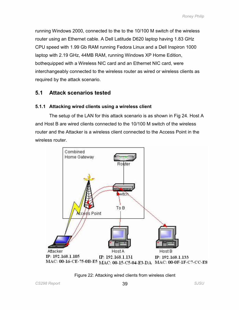
5.1.1 Attacking wired clients using a wireless client
The setup of the LAN for this attack scenario is as shown in Fig 24. Host A
and Host B are wired clients connected to the 10/100 M switch of the wireless
router and the Attacker is a wireless client connected to the Access Point in the
wireless router.
Figure 22: Attacking wired clients from wireless client
Roney Philip
CS298 Report SJSU
40
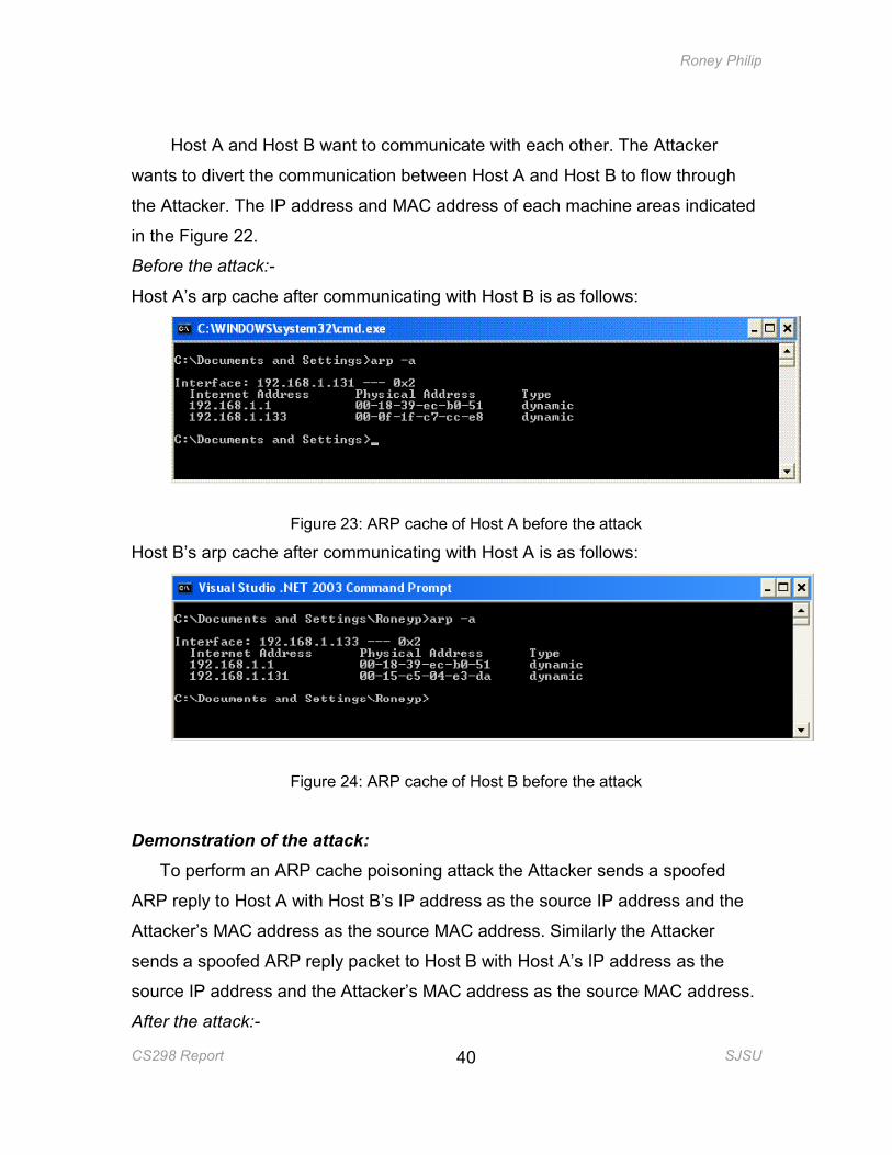
Host A and Host B want to communicate with each other. The Attacker
wants to divert the communication between Host A and Host B to flow through
the Attacker. The IP address and MAC address of each machine areas indicated
in the Figure 22.
Before the attack:-
Host A’s arp cache after communicating with Host B is as follows:
Figure 23: ARP cache of Host A before the attack
Host B’s arp cache after communicating with Host A is as follows:
Figure 24: ARP cache of Host B before the attack
Demonstration of the attack:
To perform an ARP cache poisoning attack the Attacker sends a spoofed
ARP reply to Host A with Host B’s IP address as the source IP address and the
Attacker’s MAC address as the source MAC address. Similarly the Attacker
sends a spoofed ARP reply packet to Host B with Host A’s IP address as the
source IP address and the Attacker’s MAC address as the source MAC address.
After the attack:-
Roney Philip
CS298 Report SJSU
41
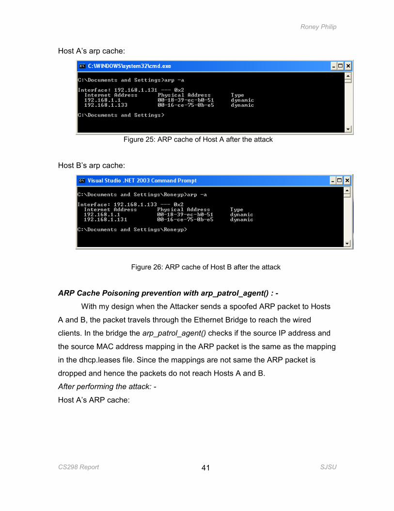
Host A’s arp cache:
Figure 25: ARP cache of Host A after the attack
Host B’s arp cache:
Figure 26: ARP cache of Host B after the attack
ARP Cache Poisoning prevention with arp_patrol_agent() : -
With my design when the Attacker sends a spoofed ARP packet to Hosts
A and B, the packet travels through the Ethernet Bridge to reach the wired
clients. In the bridge the arp_patrol_agent() checks if the source IP address and
the source MAC address mapping in the ARP packet is the same as the mapping
in the dhcp.leases file. Since the mappings are not same the ARP packet is
dropped and hence the packets do not reach Hosts A and B.
After performing the attack: -
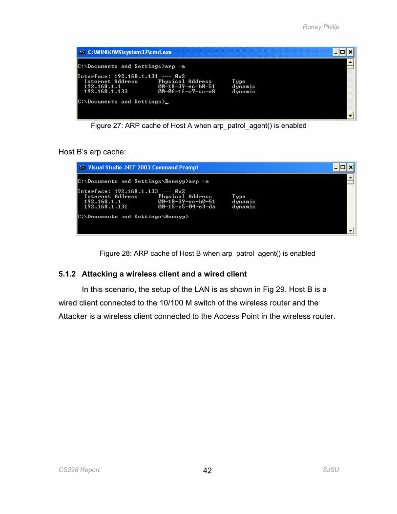
Host A’s ARP cache:
Roney Philip
CS298 Report SJSU
42
Figure 27: ARP cache of Host A when arp_patrol_agent() is enabled
Host B’s arp cache:
Figure 28: ARP cache of Host B when arp_patrol_agent() is enabled
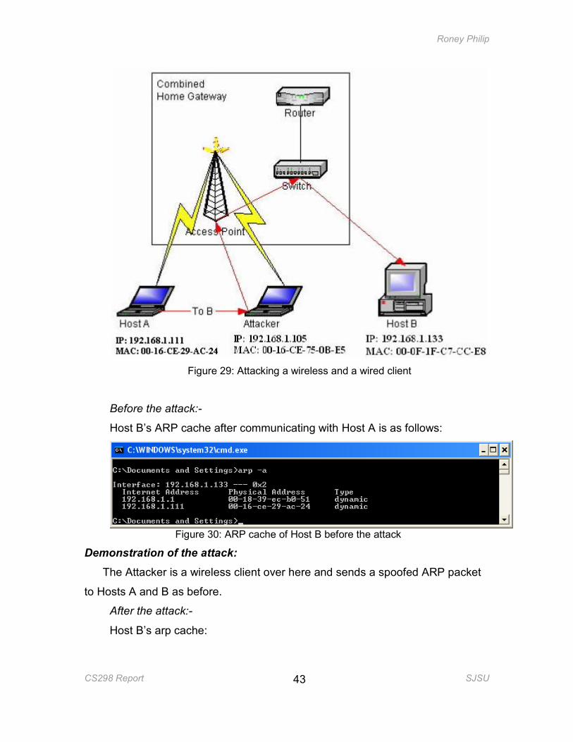
5.1.2 Attacking a wireless client and a wired client
In this scenario, the setup of the LAN is as shown in Fig 29. Host B is a
wired client connected to the 10/100 M switch of the wireless router and the
Attacker is a wireless client connected to the Access Point in the wireless router.
Roney Philip
CS298 Report SJSU
43
Figure 29: Attacking a wireless and a wired client
Before the attack:-
Host B’s ARP cache after communicating with Host A is as follows:
Figure 30: ARP cache of Host B before the attack
Demonstration of the attack:
The Attacker is a wireless client over here and sends a spoofed ARP packet
to Hosts A and B as before.
After the attack:-
Host B’s arp cache:
Roney Philip
CS298 Report SJSU
44
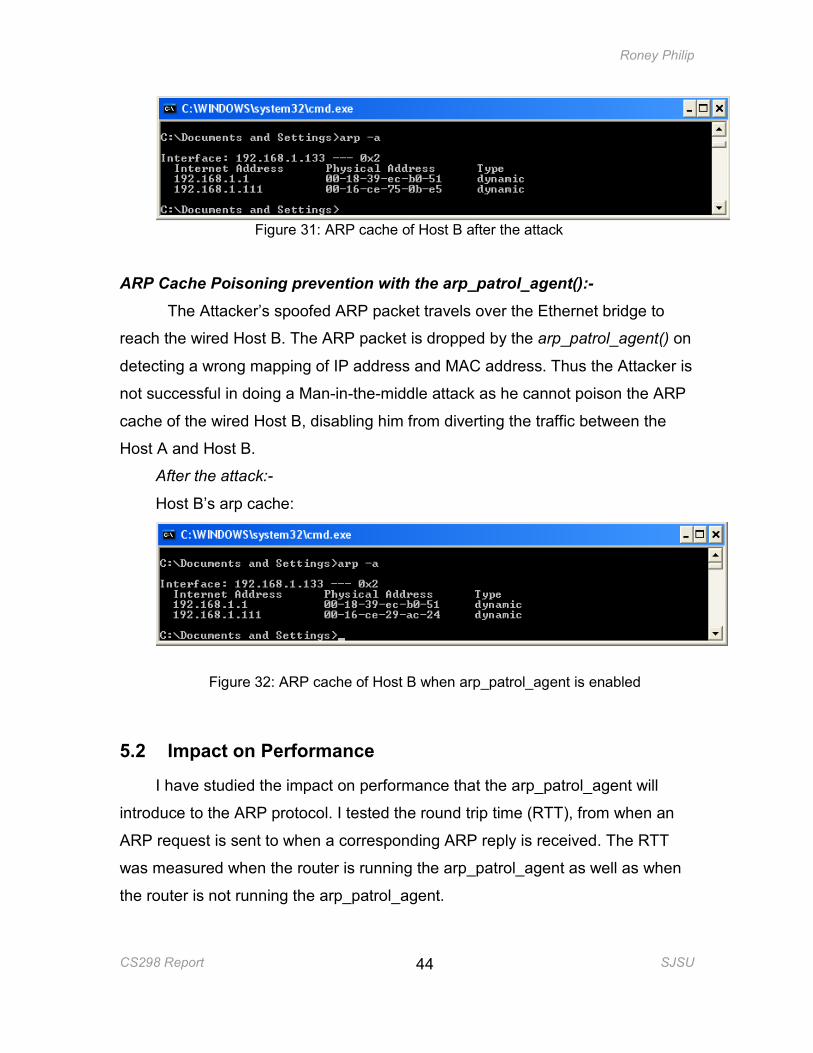
Figure 31: ARP cache of Host B after the attack
ARP Cache Poisoning prevention with the arp_patrol_agent():-
The Attacker’s spoofed ARP packet travels over the Ethernet bridge to
reach the wired Host B. The ARP packet is dropped by the arp_patrol_agent() on
detecting a wrong mapping of IP address and MAC address. Thus the Attacker is
not successful in doing a Man-in-the-middle attack as he cannot poison the ARP
cache of the wired Host B, disabling him from diverting the traffic between the
Host A and Host B.
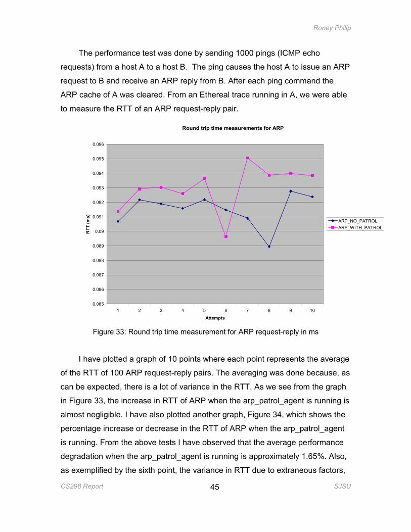
After the attack:-
Host B’s arp cache:
Figure 32: ARP cache of Host B when arp_patrol_agent is enabled
5.2 Impact on Performance
I have studied the impact on performance that the arp_patrol_agent will
introduce to the ARP protocol. I tested the round trip time (RTT), from when an
ARP request is sent to when a corresponding ARP reply is received. The RTT
was measured when the router is running the arp_patrol_agent as well as when
the router is not running the arp_patrol_agent.
Roney Philip
CS298 Report SJSU
45
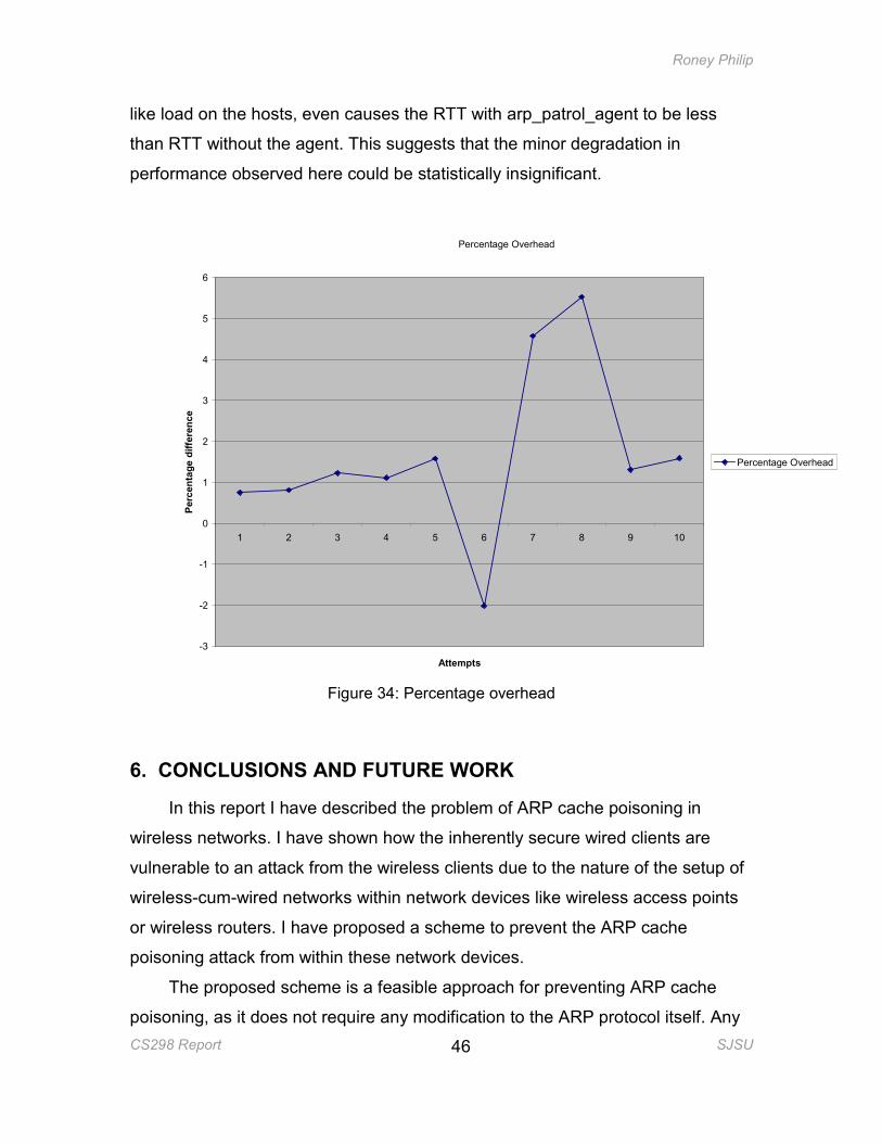
The performance test was done by sending 1000 pings (ICMP echo
requests) from a host A to a host B. The ping causes the host A to issue an ARP
request to B and receive an ARP reply from B. After each ping command the
ARP cache of A was cleared. From an Ethereal trace running in A, we were able
to measure the RTT of an ARP request-reply pair.
Round trip time measurements for ARP
0.085
0.086
0.087
0.088
0.089
0.09
0.091
0.092
0.093
0.094
0.095
0.096
1 2 3 4 5 6 7 8 9 10
Attempts
RTT (ms)
ARP_NO_PATROL
ARP_WITH_PATROL
Figure 33: Round trip time measurement for ARP request-reply in ms
I have plotted a graph of 10 points where each point represents the average
of the RTT of 100 ARP request-reply pairs. The averaging was done because, as
can be expected, there is a lot of variance in the RTT. As we see from the graph
in Figure 33, the increase in RTT of ARP when the arp_patrol_agent is running is
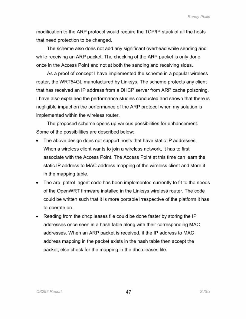
almost negligible. I have also plotted another graph, Figure 34, which shows the
percentage increase or decrease in the RTT of ARP when the arp_patrol_agent
is running. From the above tests I have observed that the average performance
degradation when the arp_patrol_agent is running is approximately 1.65%. Also,
as exemplified by the sixth point, the variance in RTT due to extraneous factors,
Roney Philip
CS298 Report SJSU
46
like load on the hosts, even causes the RTT with arp_patrol_agent to be less
than RTT without the agent. This suggests that the minor degradation in
performance observed here could be statistically insignificant.
Percentage Overhead
-3
-2
-1
0
1
2
3
4
5
6
1 2 3 4 5 6 7 8 9 10
Attempts
Percentage difference
Percentage Overhead
Figure 34: Percentage overhead
6. CONCLUSIONS AND FUTURE WORK
In this report I have described the problem of ARP cache poisoning in
wireless networks. I have shown how the inherently secure wired clients are
vulnerable to an attack from the wireless clients due to the nature of the setup of
wireless-cum-wired networks within network devices like wireless access points
or wireless routers. I have proposed a scheme to prevent the ARP cache
poisoning attack from within these network devices.
The proposed scheme is a feasible approach for preventing ARP cache
poisoning, as it does not require any modification to the ARP protocol itself. Any
Roney Philip
CS298 Report SJSU
47
modification to the ARP protocol would require the TCP/IP stack of all the hosts
that need protection to be changed.
The scheme also does not add any significant overhead while sending and
while receiving an ARP packet. The checking of the ARP packet is only done
once in the Access Point and not at both the sending and receiving sides.
As a proof of concept I have implemented the scheme in a popular wireless
router, the WRT54GL manufactured by Linksys. The scheme protects any client
that has received an IP address from a DHCP server from ARP cache poisoning.
I have also explained the performance studies conducted and shown that there is
negligible impact on the performance of the ARP protocol when my solution is
implemented within the wireless router.
The proposed scheme opens up various possibilities for enhancement.
Some of the possibilities are described below:
• The above design does not support hosts that have static IP addresses.
When a wireless client wants to join a wireless network, it has to first
associate with the Access Point. The Access Point at this time can learn the
static IP address to MAC address mapping of the wireless client and store it
in the mapping table.
• The arp_patrol_agent code has been implemented currently to fit to the needs
of the OpenWRT firmware installed in the Linksys wireless router. The code
could be written such that it is more portable irrespective of the platform it has
to operate on.
• Reading from the dhcp.leases file could be done faster by storing the IP
addresses once seen in a hash table along with their corresponding MAC
addresses. When an ARP packet is received, if the IP address to MAC
address mapping in the packet exists in the hash table then accept the
packet; else check for the mapping in the dhcp.leases file.
Roney Philip
CS298 Report SJSU
48
REFERENCES
[1] Fleck, B., Dimov, J., Wireless Access Points and ARP Poisoning: Wireless
vulnerabilities that expose the wired network.
www.eecs.umich.edu/~aprakash/eecs588/handouts/arppoison.pdf
[2] Issac, B.; Mohammed, L.A. (2005), Secure unicast address resolution
protocol (S-UARP) by extending DHCP, 13th IEEE International Conference
on Networks
[3] Whalen, S.,(2001) An Introduction to ARP Spoofing
www.node99.org/projects/arpspoof/arpspoof.pdf
[4] A Survey of 802.11 a Wireless Security Threats and Security Mechanisms
www.itsec.gov.cn/webportal/download/75.pdf
[5] DHCP – Another Untrustworthy Service
http://www.spirit.com/Network/net0202.html
[6] OpenWrt Docs
http://wiki.openwrt.org/
[7] Droms, R. Dynamic Host Configuration Protocol, RFC2131
[8] Arbaugh , W.A., Shankar, N., Wan, Y.C.J., (2001) Your 802.11 Wireless
Network has No Clothes.
[9] Brushi, D., Ornaghi, A., Rosti, E. (2003), S-ARP: A Secure Address
Resolution Protocol, Proceedings of the 19th Annual Computer Security
Applications Conference.
Roney Philip
CS298 Report SJSU
49
[10] Tripunithara, M.V., Dutta, P. (1999). A Middleware Approach to
Asynchronous and Backward Compatible Detection and Prevention of ARP
Cache Poisoning, 15th Annual Computer Security Applications Conference
(ACSAC '99), 303.
[11] A Map of the Networking Code in the Linux Kernel 2.4.20
http://datatag.web.cern.ch/datatag/papers/tr-datatag-2004-1.pdf
[12] Ebtables/iptables interaction on a Linux-based bridge
http://ebtables.sourceforge.net/br_fw_ia/br_fw_ia.html
[13] Stevens, R. W. TCP/IP Illustrated, Volume 1: The Protocols. Addison–
Wesley Professional Computing Series, January 1994.
[14] Gast, M. 802.11 Wireless Networks: The Definitive Guide. O’Reilly
publishing, April 2002
[15] Strebe, M. and Perkins, C. TCP/IP from a security viewpoint, Microsoft
TechNet
http://www.microsoft.com/technet/archive/winntas/maintain/tcpip.mspx?mfr=
true
[16] Network Bridge
http://en.wikipedia.org/wiki/Network_bridge