Embed Size (px)
Citation preview
83
Security Analysis of Logic Obfuscation Jeyavijayan l~ajendrant, Youngok 1-'inot, O"'gur Sinanoglu~, and ltamesh l<arrit
tPolyl.echnic Tnstil.ul.e or New York UniversiLy tAir Force Research Labs ~]New· York University-Abu Dhabi
ABSTRACT Due to globalh:ation of Integrated Circuit (!C) design flmv, rogue elements in the supply ch<:\in nm pirate ICs, overbuild ICs. a.ml insert ha.rdware trojaus. EPIC [1] obfuscates the design by randomly inserting additional gates; only a correct key makes the design to produce correct outputs. vVe demonstrate that an attacker can decipher the obfuscated net.list, in a time linear to the number of keys, by sensitizing the key values to the output. \Ve then develop techniques to fix this vulnerability and make obfiu:;ca.tion truly exponential in the number of inserted keys.
Categories and Subject Descriptors K.G.G [Management of Computing and Information Systems]: [Security and Protection-Physical Security]
General Terms Security
Keywords IP protection, Logic obfuscation
1. INTRODUCTION
1.1 Motivation- Preventing IP Piracy Globaliz:ation of Integrated Circuit (IC) desigu is mak
ing IC/ Intellectual Property (IP) designers and users reevaluate their trust in hanhvare [2]. As the IC design flow is distributed worldwide, hanhvare is prone to new kinds of attackR Rnch as rcvcrRc engineering and IP piracy [1]. An attacker, anywhere in this design fl.ow, can reverse engineer the functionality of an IC/ IP. One can then Rteal and claim ownership of the IP. An untrusted IC foundry may overbuild ICs aml sell them illegally. Finally, rogue clements in l.he l'oundry may insert malicious circuits (hardware trojans) into the design \Vithout the designer's knowledge [3]. Beca use of these altacks, the semiconductor induslry loses $4 billion annually [ 4].
If a designer can hide Lhe functionali(,y of an IC while it pas~e::; through the different, potentially untrustworthy phases of the design flow, these attacks can be tlw.rarted [1].
1.2 Logic obfuscation Logic obfuscation hides the functionality and the imple
mentation or a design by inserling additional gates i nLo lhe original design. In order for the design to exhibit its correct runc:Lionality (i.e., produces correct outputs), a valid key has to be supplied to the obfuscated design. The gates inserted for obfuscation are the key-gates. Upon applying a wrong key, the obfuscated design will exhibit a wrong functionality (i.e., produce wrong outputs).
Consider the circuit shown in Figure 1 >vhich is obfuscated using key-gates Kl and K 2. The inputs I1 - J() arc the functional inputs and Kl and K2 are the key inputs connected to the key-gates. On applying the correct key
Pcnnission to make digital or hard copies or all or pan of this work for personal or classroom usc is gramcd without kc prov idcd that copies arc not made or distributed for proliL or commercial advantage and that copks bear thi s noti ce and the full citation on the first page. To copy otherwise, to r epublish, to post on servers or to redistribute to lists, r equires prior specific permission and/or a fcc. DAC 2012, .Tune 3-7. 2012, San Francisco, California, USA. Copyright 20 12 ACM ACM 978- l-4503-1199- l/12/06 .. . $ 10.00.
values (Kl=O and K2=1) the design will produce a correct output: otherwise, it. v.rill produce a wrong output.
K1 x,, 11
12 13
14 15 16 __ ___.
K2-------'
' .... _....,..x, 01
02
Figure 1: A circuit obfuscated using Lwo key-gaLes Kl and K2 ba.sed ou the technique proposed iu [1]. By <>pplying the input pattern 100000, an attacker can sensitize key hits Kl and K2 to the outputs 01 and 02, and observe their va1u•\'>.
EPIC [1] incorporates logic obfuscation into the lC design flow, as shown in Pigure 2. Tn the untrusled design phases, the lC is obfuscated and its functionality is not revealed. Post-fabrication, the IP vendor activates the obfuscated design by applying the valid key. The keys are stored in a tamper-evident memory inside t he design to prevent access to an attacker, rendering thes key inputs unaccessible by an attacker.
1.3 Attacks against logic obfuscation The purpose of logic obiitscation is ddcated if an atta.cker
can determine the secret keys used for obfuscation. By determining the keyR, one can decipher the functional netliRL and make pirated copies and sell lhem illegally.
\Ve propose an attack where the attacker applies specific inpul paLterns, observes the outputs ror these pattern, and deciphers the secret key. To perform this attack, one needs the obfuscated netlist and a. functional IC. An aLLacker can obtain the obfuccated uetlist from ( 1) the IC design, or by reverse engineering the (2) layout, (3) mask, or (-1) a manufactured IC as shown in Figure 2. The functional IC. (5) in Figure 2, is bought in the open market.
The value of an unknmvn kev can be determined if it can be sensitized 1 to an output witl.wut being masked/ corrupted by the other key-bits and inputs. I3y observing the output, the sensitized key bit can be determined, given that other key-bits (similar to unknown X-sources2
) do not interfere with the sensitized path.
Once an attacker determines an input pattern that propagates t.hc key-hit value to an output without any interference, it is applied to the functional IC i.e ., the IC ;vith the correct. keys. Now, this paUern will propagate lhe correet key value to an output. An attacker can observe this output and resolve Lhe value of that key-biL.
Motivational example 1 (attack): Consider the key input K1 in l•'igure 1. It will be sensitized to output 01 if the value at the other input of gate G6 is 0 (non-controlling value for an OH, gate). This can be achieved by setting 11=1. I2=0 and 13=0. As the attacker has access to the functional IC, one ca.n apply this pattern a.nd determine the value of Kl on 01. For exa.rnple, if the va.lue of 01 is 0 for t ha.t input pattern, then Kl = 0, otherwise Kl= 1.
1 Sensitization of an internal line I to an output 0 refers to the condition (value;; applied from the primary iuputs to justify the side input of gates on the path from l to 0 to the non-controllable values of the gates) which bijectivcly maps l to 0 and thus renders anv change on l observable on 0 . 2X-sourccs: Uninitializcd I~lCmory unitR. bus contentions or multi-cycle paths arc the source ·of unknown response bitR , i.e ., unknown-Xs in testing. They arc non-controllable.
84
Trusted design regime Untrusted design regime
IC Layout . . Packaging Trusted desig
regime Market
design generation Fabnca!lon
tl .t ~ ne1s ,CD~
', \
' Reverse engineering
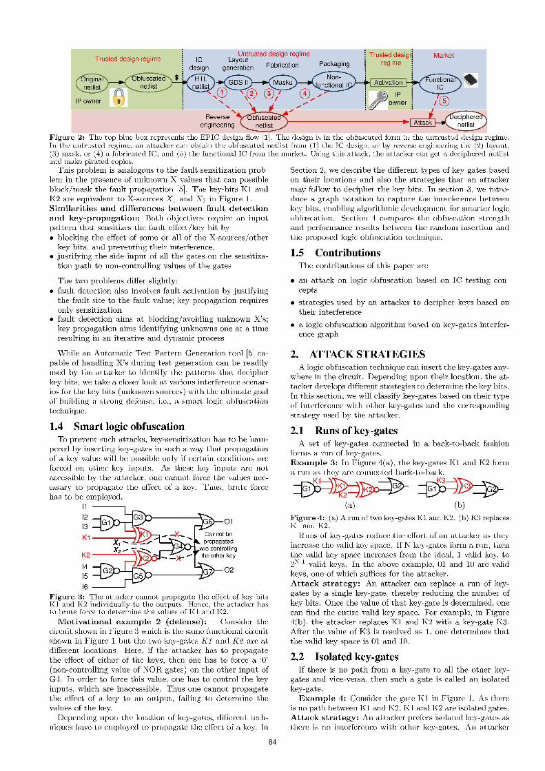
• Figure 2: The top blue box repre~ent~ the EPIC de~ign flow [1]. The design is in the obfu~cated form in the untrusted de~ign regime. In the untrusted regime, an attacker can obtain the obfuscated net list from (1) the IC design, or by reverse engineering the (2) layout, (3) mask, or ( 4) a fabricated IC, and (5) the functional IC from the market. Using this attack, the attacker can get a deciphered netlist and make pirated copies.
This problem is analogous to the fault sensitization problem in the presence of unknown-X values that can possible block/mask the fault propagation [5]. The key-bits K1 and K2 are equivalent to X-sources X1 and X2 in Figure 1. Similarities and differences between fault detection and key-propagation: Both objectives require an input pattern that sensitizes the fault effect/key bit by • blocking the effect of some or all of the X-sources/other
key bits, and preventing their interference. • justifying the side input of all the gates on the sensitiza
tion path to non-controlling values of the gates
The two problems differ slightly: • fault detection also involves fault activation by justifying
the fault site to the fault value; key propagation requires only sensitization
• fault detection aims at blocking/ avoiding unknown X's; key propagation aims identifying unknowns one at a time resulting in an iterative and dynamic process
·while an Automatic Test Pattern Generation tool [5] capable of handling X's during test generation can be readily used by the attacker to identify the patterns that decipher key bits, we take a closer look at various interference scenarios for the key bits (unknown sources) with the ultimate goal of building a strong defense, i.e., a smart logic obfuscation technique.
1.4 Smart logic obfuscation To prevent such attacks, key-sensitization has to be ham
pered by inserting key-gates in such a way that propagation of a key value will be possible only if certain conditions are forced on other key inputs. As these key inputs arc not accessible by the attacker, one cannot force the values necessary to propagate the effect of a key. Thus, brute force has to be employed.
11
K2 ----=---\
14 15
16
01
02
Figure 3: The attacker cannot propagate the effect of key bits K1 and K2 individually to the outputs. Hence, the attacker has to brute force to determine the values of K1 and K2.
Motivational example 2 (defense): Consider the circuit shown in Figure 3 which is the same functional circuit shown in Figure 1 but the two key-gates Kl and K2 are at different locations. Here, if the attacker has to propagate the effect of either of the keys, then one has to force a '0' (non-controlling value of NOR gates) on the other input of G4. In order to force this value, one has to control the key inputs, which are inaccessible. Thus one cannot propagate the effect of a key to an output, failing to determine the values of the key.
Depending upon the location of key-gates, different techniques have to employed to propagate the effect of a key. In
Section 2, we describe the different types of key-gates based on their locations and also the strategies that an attacker may follow to decipher the key bits. In section 3, we introduce a graph notation to capture the interference between key bits, enabling algorithmic development for smarter logic obfuscation. Section 4 compares the obfuscation strength and performance results between the random insertion and the proposed logic obfuscation technique.
1.5 Contributions The contributions of this paper are
• an attack on logic obfuscation based on IC testing concepts
• strategies used by an attacker to decipher keys based on their interference
• a logic obfuscation algorithm based on key-gates interference graph
2. ATTACK STRATEGIES A logic obfuscation technique can insert the key-gates any
where in the circuit. Depending upon their location, the attacker develops different strategies to determine the key bits. In this section, we will classify key-gates based on their type of interference with other key-gates and the corresponding strategy used by the attacker.
2.1 Runs of key-gates A set of key-gates connected in a back-to-back fashion
forms a run of key-gates. Example 3: In Figure 4(a), the key-gates K1 and K2 form a run as they are connected back-to-back.
~~~~~ (a) (b)
Figure 4: (a) A run oftwo key-gates K1 and K2. (b) K3 replaces K1 and K2.
Runs of key-gates reduce the effort of an attacker as they increase the valid key space. If N key-gates form a run, then the valid key space increases from the ideal, 1 valid key, to 2!\-l valid keys. In the above example, 01 and 10 are valid keys, one of which suffices for the attacker. Attack strategy: An attacker can replace a run of keygates by a single key-gate, thereby reducing the number of key bits. Once the value of that key-gate is determined, one can find the entire valid key space. For example, in Figure 4(b), the attacker replaces K1 and K2 with a key-gate K3. After the value of K3 is resolved a.<; 1, one determines that the valid key space is 01 and 10.
2.2 Isolated key-gates If there is no path from a key-gate to all the other key
gates and vice-versa, then such a gate is called an isolated key-gate.
Example 4: Consider the gate K1 in Figure 1. As there is no path between K1 and K2, K1 and K2 are isolated gates. Attack strategy: An attacker prefers isolated key-gates as there is no interference with other key-gates. An attacker

85
identifies a pattern that uniquely propagates the effect of an isolated key-gate's key to an output. One then applies the pattern to the functional IC and determines its value.
As mentioned before, in Figure 1, the pattern lOOXXX propagales the value of"K1 to output 01. An aLlacker, upon observing this output, can identify that the value of Kl is 0.
2.3 Dominating key-gates If chere are 01vo key-gates K1 and K2 such chaL K2 lies on
every path between Kl and the output;;. then K2 is called a dominating key-gate. Example 5: The gate K2 in Figure 5 is a dominating keygate.
FigUI·e 5: K2 is a dominating key-gate whose key bit value can be determined only after muting L.he eJfecL. of Kl. PaLL.en1s that make either C = 0 and A= ·l or C= O and R = "I will mu te the effect of K l. However, only if A = 1, the effect of K2 can reach 01.
Attack strategy: An aHacker can deLermine che value of K2's key bit only if the effect of Kl 's key bit is prevented (muted) from reaching key-gate K2 while simultaneously sensitizing K2's key bit to an output. An input pattern that ccm perform muting as well a,s sensitization is ca,lled the golden pattern. On applying thi;; golden pattern. the attacker can determine the value of K2. If muting of Kl and propagation of K2 cannot be performed simultaneously, then the attacker cannot determine value of K2. In such Cll.<;cs. the golden pattern docs not exist, forcing an attacker to employ brute f<xce.
The effect of a key can he muted before it reaches the other key, by using patterns that force controlling values in any of the ga.tes on the path between Kl and K2. If there are mulliple paths f'rom key-gaLes Kl and K2, then lhe efl€d. of key-input Kl has to be muted on every path.
Example 6: Consider the circuit. show·n in Figure 5. K2 can be determined only if the effect of Kl is muted. lf there is a paLLern that. jusunes the output or C5 to 1, lhen the effect of Kl will be muted. Pa.ttern~ tha,t make either C = 0, or A=l and I3 =1 \viii a.~sure this condition, thereby muting the effect of Kl. However, the atta.cker should ~elect the pattern that propagates the effect of K2 to an output. If C =0, G7 blocks the propa,gation of K2 as its output will always be n. The condition A = L allows K2 to propagate through GG. Hence, an attacker will select the pattern that m akes A = l a nd C = 0, so that one ca.n mute the effect of Kl as well as propagate the cffc-et. of K2 to an output.
2.4 Convergent key-gates Even if' there are no paths between two key-gates, lhe
sensitization paths might interfere. Such scenarios happen if" these t \1!0 or more key-gates converge. Depending upon the type of convergence, key-gates can be classified into 1) concurrently mutable, 2) sequentially mucable, and 3) nonmuta ble key-gate;; .
2.4.1 Concurrently mutable convergent ke_v-gates If two key-gates Kl and K2 converge at some other gate,
such that TO's key bit can be determined by muting K2, and K2 's key bit can he determined by muting Kl , t hen Kl and K2 are called concurrently nmtable key-gates.
~~~~ ~=i~01 ~~1
w (~ Figure 6 : (a ) Concurrently mutable key-g ates: Kl and K 2 converge <>t G5 and c;-..u b e muted . (b) Sequentially m utable keygate~ : Kl and K2 converge at G4, but only Kl can b e muted.
Example 7: Consider the circuit shown in Figure G(a). The key-gates Kl and K2 converge at the gate G5. The value or Kl can be determined by applying a pallern that mutes K2 (B= O). Similarly, the value of K2 can be determined by applying a. patlern GhaJ.. mutes K1 (A=l ). Attack strategy: The a,ttacker determines the golden pattern that mutes one key and simultaneously sensitizes the other key to <:m output, or vice-versa.. If a. golden pa,ttern does not exist, then the attacker has to p erform brute force only on that set of concurrently muta.hle key-ga.tes.
2.4.2 Sequentially mutable convergent key-gates If two gates Kl and K2 converge at some other g·atc, such
that K2's key bit can be determined by muting Kl 's key while K2's key cannot he muted to determine Kl'H key, then Kl and K2 arc called sequentially nmtahlc convergent keygateR, aR they can be deciphered only in a. particula.r order.
Example 8: Consider the circuit shown in Figure G(b). The value of K2 ca.n be determined by a.pplying a. pa.ttcrn that mutes Kl (A= l), while K2 cannot be muted as it direccly feeds the gale where 1<1 and K2 converge. Attack strategy: An all.a.cker will rirst dete rmine K2's value by muting Kl using the golden pattern. One then updates t.he net.lisl. by replacing K1 wil.h a buller or an inverter based on the value of K2. Then Kl is ta rgeted. If the golden pattern does uot exist, then the attacker ha;; to perform brute force ouly on that set of ~equentially muta.ble key-gates.
2.4.3 Non-mutable convergent key-gates If two key-gates Kl and K2 converge at some other gate,
such t hat neither of the key bits can be muted, then Kl and K2 arc called non-mutable convergent key-gates. Example 9: Consider the circuit sho;vn in Figure 3. The key-gates Kl and K2 arc connected to the same gate G4. Attack strategy: To propaga.le either of the key bits the other one has to be muted. However, as an attacker cannot access key inputs, one cannot. f'orce those va lues. Hence, one is forced to perform brute force attacks.
Input : Obfn~cated netlist, Functional IC, Key Inputs Output: Original nctli st Determine Run.> of Keys; Replace them ,,-ith XOR gates: Update Netlist; for tlu: rr~ma:ining k~ys do
For each T.wlated J(ey do
I Compnte and apply propagation pattern; Detcrrninc f(eyRi.t.s ami upcla.t.c Nct list.;
end For each Consec ut ive]] Concur-r-ent jj Sequcntial /,,ey do
if the.Te. exists a golden patte.nt then
I Apply the golden pat.tcm; Determine KeyiJit.s , Cpdate Netlist., Break:
else I App lyBruLeForce(), Break:
end end For each 1Von-nwlable Key do I ApplyBmtcFmcc(), Break;
end end
ApplyBruteForce(); For each possible key combination do
Generate random input p<'lt tent8; Simulate the patterns a.nd obtain the outputs OF",.,,._ : Apply the pa t Lerns on IC and obtain the ouLpnts OPeu; if O~,;m==01-'en then
I \~alid Key "': c urrenL key combinaLion; 1,; pdatc ueth8t;
end end
Algorithm 1: Attack on logic obfuscation.
2.5 An attacker's action plan By considering all the different types of interference be
tween key-gat es, an a ttacker uses Algorithm 1 to determine

86
the secret key. The attacker first removes the runs of keygates and targets the isolated key-gates. Each isolated gate can be removed by one test patterns. After that, one targets consecutively mutable, concurrently nmtable, and sequentially muLable key-gates. Only if" one is able t.o generate a golden pattern that simultaneously mutes effects of the other keys and sensiU~es the efl"ecl or the tarp;et key, the value of the target key can be determined. Finally. the nonmutable ke.ys are identined via brute force. As the key bits are identified gradually in every iteration. the cone:-;pondiug key-gates can be replaced by a buffer or an inverter, possibly changing the type of other key-gates. Tlm:-;, in every iteration, the key-gate types need to be re-computed.
3. STRONG LOGIC OBFUSCATION Strong logic obfuscation hinges on inserting key-gates with
complex interferences among thern. Next, we relate types of key-gates to the kind of interference they introduce using a graph-based notation.
3.1
~~
~~ (e)
02
Figure 7: (a) An example circuit with three key-gates. (b) Interterence graph of the key-gates. Non-mutable keys arc connected by ~olid edge~. (c) If the new key-gate is inserted at the output G "10, it creates rnutn.blc edges (dotted lines) with the other key-gates (d) If the new key-gate is inserted at. the o11tpnt G5, it creates non-mutable edges (solid lines) with t he other key-gates.
To insert key-gates, 'We form an interference graph of keyg·ates. In this graph, each node represents a key-gate and an edge connect;.; t;vo nodes, if two gn.tCB interfere. l;.;olatcd key-gates arc represented with isolated nodes. A run of keygates is denoted by a single node . Non-mutable key-gates arc represented arc connected with non-nmta.ble edges. eoncurrcntly mutable key-gates arc conncetcd with rnutablc edges. Sequentially mutable key gales are connected by two edges; a non-mutable edge arises !"rom the key-gate that is nonmutable and a mutable edges arises from the key-gate that is mutable.
Example 10: Consider the cireuit with three key-gates :-;hmvn in 7(a). They interfere >vith each other a:-; follows
• Kl ami K2 are non-mutable and :-;o they are connected by non-mutable edges as shown in Figure 7 (b).
• The key-gate:-; Kl a.ml K3 converge at the ga.te G6, hence they are eonverging key-gates. Specifically, they are sequentially convergent; K3 's effect cannot be muted while Kl 's effect can be rnut.ed by applying 15=0. However if Ir• is 0, then both key bits arc blocked 11.t G8. Hence, Kl and K:3 arc non-nmtable and so they arc connected by non-mutable edges a.s shown in Figure 7(b ).
• K2 and K3 eonvcrgc at the gate G9, through G3 and G7, respectively. However, neither of the key hits can be muted and sensitized individually. K>r instance, making IG= L mutes K2 but also blocks the sensitization of K3 at GlO. \'laking 17= 1, mules K:3 but. also blocks the sensitization of K2 at G 10. Hence , K2 and K :3 arc non-mutable as shown in Figure 7(b).
For a strong·cr logic obfuscation, the nmnbcr of non-mutable edges in the interference graph should be maximized, as they foree an attacker to perform brute force. On the other hand, if there arc more mutable edges, then the attacker can mute the efl"ecl of" keys and can easily determine lheir values. Hence, a defender prefers non-mutable edges to mulable edges.
Example 11: Consider the circuit shown in Fig 7(a). If a ne\v key-gale, 1<4. is i nserled at the output of C 10, then it creates mutable edges with all the other key-gates. By setting 16= 1 or 17= 1. the attaeker can mute the effects of Kl. K2, ami K3. a.nd can decipher easily. lienee, G 10 i:-; connected with mutable edges with the other key-gates as shown in Figure 7 (c).
If the new kcy-ga.tc, K4, is inserted at the output of G5, then it creates non-mutable edges with the other key-g·ates a.s shown in Figure 7(d). Thus, it is better to insert the nc>v kcy-gatcR at the output of G~ ..
Input : Original nct.list, KeySiv.e Output: Obfuscated net.list KcyGateLocations = {}: Hamlomly insert 10'1.. key-gates; Add that location to KevGateLocations: Const.mcl. KeyGraph; ., · for i .__ 2 to J(eySize do
For each Ga{ei in ]llellisl do if Gatei rf. Kc:yGateLowtiuns then
Cum. Weight = 2::: weight of edge~ in KeyGraph: For each K ~y-gtJ.I.ek in KeyGo.l.eLom{ions do
I c.:n~L Wei~.hti += FincLvietric(Gate.i. I<..e}-gatek)·
end end
end Select the Gate with the highest Hardness Metric; Add the selected gate to KeyCateLocations; Insert a key-gate at the ouLp ut of L.he selected gate; Update KeyGraph:
end
FindMetric (1(1, K2); if K1 and K 2 are isolaled then Return 0; if K1 and K2 are con8ecutiveliconcurrentllsequ.entio.l then
I
if a golden pattern exists then Return weight of mutable edge; else Return weight of non-mutable edge;
end if Kl arH.l K2 arc non-mutable then Return weight of non-mutable edge:
Algorithm 2: Insertion of key-gates
3.2 Insertion of key-gates A defender can use the interference graph to insert key
gates. Algorithm 2 is used to insert key-gate:>. At every iteration, a key-gate is inserted at a location such that the nmnber of non-mutable edges in the graph is maximized.
Initially, 10% of the total key-gates arc inserted at ra.ndorn locations in the circuit. Such random distribution will insert key-gates in diff(•rcnt parts of the circuit thereby affecting multiple outputs. Here, we considered 10% for initial distribution (one also ean chose a different amount of initial distribution and the impact of this amount on obfuscation is beyond the scope of this paper). Then the graph of keygates is constructed. Then, the rcrnaining key-gates arc introduced iteratively. In every iteration, for each gate in the neLlisl, we clelermine the type or edge wilh the previously inserted key-gate. Depending upon the type of edge, we assign weights; non-mutable edges are given a higher weight than the mutable edges. \Ve then ealculate the sum of weights of edges in the g raph for that gate. The gaLe that rnaximi~es the ~mn of weight of edge~ in the graph i:-; selected, and a key-ga.te is inserted at its output. The graph is then updated by including the !le'..v key-gate. Thi~ procedure is repeated for inserting all the key-gates .
In every iteration, the defender has to check for the prescnec of golden patterns \vhich might increase the computa-
87
180
160
140
120
"' ;>.
~ 100
0 .. 80
60
40
20
tiona! complexity of the algorithm. Hence, a defender can assume that there always exists a golden pattern and skip the search for the golden pattern. This is a pessimistic scenario for a defender because some golden patterns might not exist.
4. RESULTS
4.1 Experimental Setup The proposed technique is analyzed using ISCAS-85 com
binational benchmarks. YVe used the Atalanta testing tool [6] to determine the input patterns for muting and propagation the effects of keys. To obfuscate a circuit \Vith a reasonable performance overhead, we selected the key size aB 5% of number of ga.tcR in that circuit. I:Vhilc obhtscating a circuit, we assumed that there ahva.ys exists a golden pattern. \Vhilc attacking the circuit, we used the techniques proposed in Section 2 where we search t(x the presence of a golden pattern. For every brute force attempt, we applied 1000 random pa.Lterns Lo deLermine the value of a. key. The area, pO\ver, and delay overheads were obtained using lhe Cadence HTL compiler.
\Ve compared Lhe ell"ecl-iveness or k>ur types of insertions: random-insertion [ 1], random insertion with no runs of gates, unweighted insertion \Vhere both mutable and non-mutable edges are given the ~arne 'veight of 1, and weighted insertion where non-mutable edges are given a higher weight (weight = 2) than the mutable edges (\veight = 1).
Random Random + No Runs Unweighted We~hted
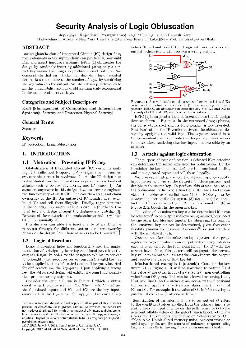
Figure 8: Types of key-gates inserted by different logic obfuscation techniques. Effective key size from an attacker 's perspective (top) and from a defender's pet·spective (bottom) are shown as numbers on top the bars.
4.2 Types of keys and effective key-size Figure 8 shovvs Lhe number or types of" keys in different.
benchmarks for different types of insertions. ln the r andom insertion method, rnosL of the keys are concurrently mutable. Some number of keys are inserted in runs benefiting the a.LLacker. Only :30% of keys are non-mutable and sequentiaJly mutable which require brute force approach. In the 'Random + No fl.uns' method, keys are not inserted in runs thereby increasing the effort of the <tttacker.
In the unweighted and weighted insertions, around 90% of keys are of non-rrmt<tble and ~equentially mut<tble types. rviost of the keys in weighted insertion is either non-mutable or scqucntiaJly mutable because they arc given a higher weight. There arc no isolated keys in either of the insertion t echniques, a.~ they arc not given any weight;.;.
Effective key size: Due to random insertion of the first 10% of key-gates, multiple disconnected graphs might cxisL wiLhi n a key-i nle rf"erence graph. The keys in a. graph can be either isolated, dominant , or convergent. Since a de-
fender pessimistically assumes that the golden patterns always exist, the effective key size from his perspective is the maximum number of non-mutable keys in a connected keyinterference graph. If there arc N non-mutable key gates (effective key-si~e), Lhe number of brute f"orce attempts is 2:-l-t. However, when an attacker tries to attack, not all lhe golden patterns will exisl. For those keys , he has Lo try for all possible combinations. Hence, from an attacker's perspec:Live, Lhe e!Ted i ve key size is Lhe largest key si~e on which brute force is attempted. If the number of brute force attempts is 2M , then the effective key si~e for an attacker is I'd.
In Figure 8, the effective key-sizes for a defender and an attacker are shown as numbers on top of the bars. For both the attacker and defender, the effective key sizes of random insertions are less than that of the unweighted and weighted insertions. Therefore, the nmnher of brute force attempts required to decipher the kcyR inserted using random inRcrtions is exponentially smaller than that of the unweighted and weighted insertions. The nt. ta.ckcr's effective key size iR always greater than that of the defender's because of the absence of golden patterns which forces the attacker to perforrn bruLe force. For example, consider Lhe benchmark C7552, the attacker needs 2140 brute force attempts and hence the eiTecLive ke_y si~e is 146. On Lhe other hand. for a defender. lhe largest number of non-rnula.ble key-gates in a. connected graph is 51 and hence the effective key size is 51.
4.3 Number of test patterns 1045 ,_-----------------------------------------,
10"
g? 1030 Q; ~ 1025 ~
; 1 o2o
0 10'5
""
R9ndom (Defender's! = Random Attacker"s =
Weighted 18efender"s = We1ghtecf (Attacker"s =
C432 C499 CBBO C1355 C1908 C2670 C3540 C5315 C7552
1040
1030 :-§: (I)
E 1020 i=
1000 years
4\Jl~~ys
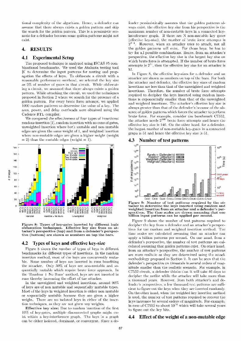
Figure 9: Number of test patterns required by the attacker to determine the keys inserted using randon1 and weighted insm·tion fron1 an attacker and a defender's perspectives. The time scales are drawn assuming that one billion input patterns can be applied per second.
Figure 9 shows the number of test patterns required to decipher the key from a defender and an attacker's perspectives for the ra.ndom and weighted insertion method. The time scales arc calculated assuming that an attacker can apply a billion patterns per second. On one hand, from a defender's perspective, the number of test patterns arc calculated a~suming that golden patterns exist. On other hand, from an attacker's perspective, the number of test patterns are more realistic: as chey are determined using the a.l.Lack methodology proposed in Section 2. It can be seen that the defender's perspective on timescale is several orders or magnitude smaller than the realistic scenario. For example, in C7552 circuit, a defender thinks that iL will Lake 46 days to decipher the netlist while the attacker will take more than a thousand ;-,rears. However, from both attacker 's and defender '~ perspectives . a few thousartd t est patterns are ~ufficient to figure out the keys when they are inserted randomly. On the other hand, when the weighted key insertion method is used, the number of test patterns required to recover the keys increases by severa l orders of magnitude. For example, in c<l.~e of C7552 to about 1018 which will take several years t o figure out the key bits.
4.4 Effect of the weight of a non-mutable edge

88
I3y incrc<J.~ing the weight of the norHrmtablc edges, the algorithm will create a design that h;m a large number of non-mutable key-gates. Table 1 shows the number of nonmutable key-gates flx different weights of non-nmt.able edges in one of the ISCAS-85 benchmark circuit. C7352. This circuit wa.~ obfu~cat.ed with 17(i key-gates. \Vhilc incre&<>ing the weight. of' th€ non-muLa.ble edges increases the number of non-mutable key-gates in the design, the rate of increase is nol Lhe same rale. I ncr€asing t.lw weighL from 1 Lo 2 increases the number of non-mutable key-gates frorn 115 to 138. Hut increasing the w€ight from 2 to 10, increases Lhe number of non-mutable key-gate;; from 138 to 1'19.
4.5 Area overhead
Hench mark
Figure 10: Area overhead for different insertion algorithms.
Figure 10 ;;hows the area overhead for different key-gate obfuscation algorithms. Ev€11 though th€ number of keygates inserted is 5% of the nmnber of gates in the original design, the area overhead is high as the key-gates are XOR/XKOR gates that consists of a large number of transistors. Unwcighted and weighted insertion techniques entail less overhead than random insertion techniques.
4.6 Power-delay product
Figure 11: Power delay product overhead for different insertion algorithms.
Figure 11 shows the power-delay product overhead for clif~ fcrent insertions . Randmn insertion yields an averFLge overhead of 25% while weighted and unwcightcd insertion yields an average overhead or 21%. To minirni"'e this overhead, one can pursu€ a. pow€r and delay constrained obfusca tion.
4.7 Logic obfuscation with PUFs Physical L~nclonable Functions (PUFs) are circuits that
leverage process variation~ in IC rmmufa.cturing, to produce ::;ecret keys. Iu [1], PUF::; are u sed to give unique key::; for each IC even though they are all obfuscated with t he same key. The design is first obfuscated with a key and a PUF circuit is attached to it. ~Cpon applying the user key (clml-
lcngc) to the PUF, the PUF's response will be the key used for obfuscation. In the proposed attack, the attacker is trying Lo rigure ouL Lhis response i.e., the k€y used for obfuscation. On getting this response, the attacker can remove the PCI' cireuit from the netlisl. and apply the correct keys directly to the original design. To break the influence of P"CFs or any cryptographic algorithms, an attacker can determine the wires that carry these signals and disconnect them.
5. RELATED WORK Logic obfuscation techniques can be broadly classified inl.o
two types-sequential and combinational. In sequential logic obfuscation, a.ddilional logic (black) sLates are introduced in the state transition graph [7]. Th€ state transition graph is modified in such a way Lhal Lhe design reaches a. valid staGe only on applying a correct ::;equence of key bits. If the key is withdrawn. the design, once again, €nels up in a black state. However, the effectivene;;s of these method::; in producing a wrong output has not been demonstrated. In combinational logic obfuscation, as mentioned b efore, XOR/XKOR gates arc introduced to conceal the functionality of a design [1].
0 bfuscation is also performed by inserting memory elements [8]. The circuit will function correctly only when these clements arc programmed correctly. However, using m emory clements will incur significant performance overhead.
6. CONCLUSION Logic obfuscation is vveak when the inserted key-gates are
isolated or their effect can be muted. If mutable gates are employed. then the attacker is able to determine the key bits \Vithin a second. However, it can be strengthened by inserting key-gates such that their effects arc not mutable. In such insertions when the key size is greater than 100, it will take several years for an attacker to determine the key hits. Our analysis reveill that even though a ddcnder pessimistically assumes a smaller effective key size, the actual key size encounlered by Lhe a.llacker is much higher.
IC testing techniques allow designers and testers to peck inl.o Lhe design, by conlrolling only Lhe inputs a.nd observing the outputs. On one hand, <til <tttacker c<tn use such capability to subvert logic obfuscation. On the other hand, <t defender cau perform better logic obfuscatiou by m<tking such process infeasible using the lessons learnt from t€sting.
7. ACKNOWLEDGEMENT This material is ba-;ed upon work funded by AFRL under
contract I\o. FA87G0-11-2-0274. Any opinions, findings and conclusions or recommendations expressed in this material arc those of the anthor(s) and do not necessarily reflect the views of AFRL.
8. REFERENCES [11 J . Roy, F . K o ushanf,.r, and I. Markov, "EPIC: Ending Piracy of
Integrated Circuit~:~." Proc . of Des-ign. Au-tornation (tnd Te~d ·in Bnrope, pp. I 069 I 07~L 2 008.
[2] "Defeu>e Sci<erKe Board (DSB} Htudy on High Performance Micruchip Supply,'' http:/ /www.acq.oHd.mil/ dsb/ reporls/ ADA435563 . pdf, 2005.
[:31 R. Karri, J. Rajcndran, K. Rosenfeld, and I\L Tchranipoor, '"11-us t.worthy Hardware: Identifying and Classifying H ardware 'T'rojans," TF;FJF: Cmnpuitr·, vol. ·1:3, no. 10, pp. :)l) c[() , 20HJ.
[4] SEl\-11: ~: Innovation i::; at ri:;k a:; ::;ernicouductor equiprueut a ud rna ter.iab iudu:;try lo;;eb up to $4 bilJiou auuually due to IP infrinJ-!;ernent: :~ '\VWW .~erui.orJ-!;/ en/P r e.ss / P04377 5 , 2 008.
[51 M. L Dushncll and V. D . AgrawuL ''Essentials of Bkct.ronic Tcst.ing for Digital, Memory, and l'vlixed-Signul VLSI Circuits," Kluwcr Academic Publishers, Boston, 2000.
[6] H. L.,., a.ud D. Ha , "An effki<ent forward fau lt Himulat ion alJ-!;urithrn ba.:;ed on the parallel pat tern Hiugle fault propaga tion," P.ruc . u.f IEEE InktwJ.ti.una./ Test Con.fer ~nce, pp. 1)46 955 , 11)9 1.
[71 R . C hakraborty a nd S. Dhunia, "HARPOON: A n O bfuscat ion-D;sed SoC Design~ Methodology for Hardware Protection,'' [V,'JD.oJ 1'ransactions on Computcr· A ,dcd Design, vaL 28 , no. 10 , pp. 149:3-1502, 2009.
[8] A .. . Bauruga.rten , A .. . T ya g: i: and .J . Zarubr euu. :~Prevt.":ntinJ-!; IC P ira.cy U.sing: R.ecoufig:ur (.l.ble Lo~ic B~-trrier~,' ~ IEEE Dt:.':iiyn u.nd Te.st of Cmnp~ukt s. vol. 2?, no . 1, pp. G6 ?5, 2010.

89
APPENDIX (The intuition behind key interference based logic obfuscation) \Vc will analvzc the kcv-intcrfcrcncc graphs of a circuit obfu~cated usir~g random -~.ml weighted insertion methods both from a defen(ler and an attad<:er's perspectives. As mentioned in Section 3. the defender always assumes that the gulden pattern, that mutes and sensiti;es the effect of keygates simultaneously, docs not exist, and constructs his key interference grnph accordingly. However, an nttackcr tries to find the golden patterns to mute key-gates to decipher the va.lue of keys, and constructs his key iuterference graph accordingly.
A. RANDOM INSERTION
0G0G A \,I//
v K4
(a)
(b) - Dominant Sequentially mutab<> - Consecutively mutable -Non-mutable
FigUI'e 12: Key-interference graphs of C4!HJ . an TSC :\S-85 benchmark circuit., obfuscated wit.h 11 key-ga Les. DoLled hnes represent mutable· edges and solid lines represent non-nmtable edges. (a) Key-interference graph from a defender's perspective with an assttmpt ion that. the edge K11---+K:3 is mutable_ (h) Keyinterference graph from an attacker's perspective. The golden pat tern to mute the edge Kll ---+ K:1 does not exist.
Defender's perspective: Figure 12 s hows che key interference graph of one of the lSCAS-85 benchmark circuit, C499, whic~t is obfu.scated by ~~~serting 11_ key-gates . Ke~;g·ates K5, K8, and K9 are class1fied as dormnant key-gates . Key-gates K;~ and Kll arc classified a.~ consecutively nmtablc key-gates. Key-gates KL K2, K7, and KlO arc classified as sequentially mutable key-gates. Key-gates K4 and KG are classified as non-mutable key-gates. l•'rom a defender's perspective, since there two non-mutable key-gates , the effective key size is two.
Attacker's perspective: Consider the scenario \vhere an attacker tries to search for the golden pattern for the cdg·c Kll--4K;) that sinmltanconsly mutes Kll and sensitizes K:3. He concludes that RlH'h a pattern docs not exist. ThuR, from an attacker 's perspective, the edge from Kll--4 K3 is nonmutable as shown in Figure 12(b). Hence, the key-gates K3 and Kll are classified as sequentially mutable key-gates. As the largest key size on which brute force is attempted is two, the effective kev size is two. I\otice that even though eleven key-ga tes arc i~scrtcd, the effective key size is only tvvo.
B. WEIGHTED INSERTION
:;Please refer Section 2 for the definitions of different types of key-gat es.
Sequentially mutable -Non-mutable
Figure 13: Key-interference graph of C--Wn from a dcicnder's perspective with an assumption that the edges Kl---+K2, Kl-+K5, Kl---+KlO. and Kl---+Kll arc nwtablc. DoLLed lines rcpre~enL mutable edg~ and solid lines represent non-mutable edges. Effective key ~ize is 10.
- Non-mutable
Figure 14: Realistic Key-interference graph of C4UU frow an a ttacker's perspective. The golden patterns to mute the edges Kl--tK2. Kl ---+K5 . Kl ---+KlO. and Kl---+Kll do not. exist. lienee, K'l is n<)n-mutablc increasing the effective key si 7.C to 11.
Defender's perspective: As shown in Figure 12(a), the edges Kl--4K2. Kl--4K5, Kl--4Kl0, and Kl--4Kll are mutable. Hence. the key-gate Kl is classified as a sequentially mutable key-gate and all the other gates arc classified as non-mutable key-gates. From a defender's perspective, since there arc ten non-mutable key-gates, the effective key size is len.
Attacker's perspective: The attacker searche~ for the golden pattern that mutes the key-gate Kl. As such a pattern docs not exist. he classifies the edges K 1--+ K2, K 1--+ K5, Kl--4Kl0. Ftnd Kl--4Kll FIR non-mut~blc. Therefore, the key-gate Kl 11.lso becomes non-mutnblc. AR the attacker has to trv all combinations of the kevs, Kl to Kll , the effective kev si~e is eleven. \Vhile the efreccive key si~e in random in~ertion is two, the proposed method has an effective key size of eleven.