Embed Size (px)
Citation preview
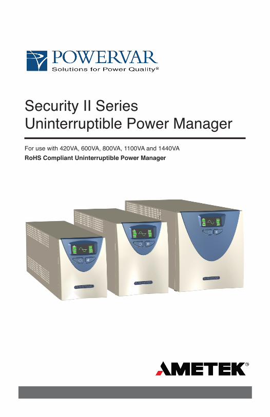
Security II SeriesUninterruptible Power ManagerFor use with 420VA, 600VA, 800VA, 1100VA and 1440VARoHS Compliant Uninterruptible Power Manager
2 A01-00055 Rev J
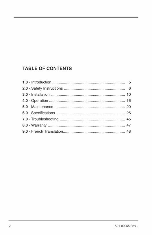
1.0 - Introduction .................................................................... 52.0 - Safety Instructions ......................................................... 63.0 - Installation ..................................................................... 104.0 - Operation ....................................................................... 165.0 - Maintenance .................................................................. 206.0 - Specifications ................................................................ 257.0 - Troubleshooting ............................................................. 458.0 - Warranty ........................................................................ 47 9.0 - French Translation.......................................................... 48
TABLE OF CONTENTS

3A01-00055 Rev J
IMPORTANT NOTICE ON BATTERY WARRANTY
The warranty policy stated in Section 8 is not valid for applications in which the UPM is regularly and intentionally disconnected from AC mains power. AMETEK-Powervar’s two year battery warranty applies only to products that are properly installed and consistently connected to AC mains power, except during utility outages.
Products regularly and intentionally disconnected from AC mains power will experience substantially reduced battery life. AMETEK-Powervar’s standard warranty term does not apply in these cases and is supplanted by a 90-day warranty from time of shipment from AMETEK-Powervar. The warranty provided by AMETEK-Powervar provides for the replacement of the battery or battery systems in the event that the batteries do not meet performance specifications as determined by AMETEK-Powervar exclusively.
4 A01-00055 Rev J
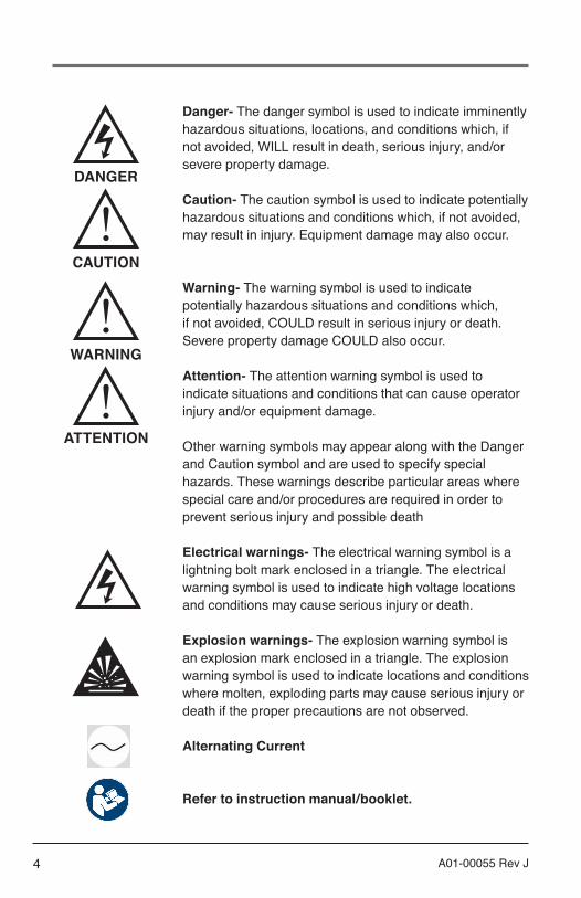
Danger- The danger symbol is used to indicate imminently hazardous situations, locations, and conditions which, if not avoided, WILL result in death, serious injury, and/or severe property damage.
Caution- The caution symbol is used to indicate potentially hazardous situations and conditions which, if not avoided, may result in injury. Equipment damage may also occur.
Warning- The warning symbol is used to indicate potentially hazardous situations and conditions which, if not avoided, COULD result in serious injury or death. Severe property damage COULD also occur.
Attention- The attention warning symbol is used to indicate situations and conditions that can cause operator injury and/or equipment damage.
Other warning symbols may appear along with the Danger and Caution symbol and are used to specify special hazards. These warnings describe particular areas where special care and/or procedures are required in order to prevent serious injury and possible death
Electrical warnings- The electrical warning symbol is a lightning bolt mark enclosed in a triangle. The electrical warning symbol is used to indicate high voltage locations and conditions may cause serious injury or death.
Explosion warnings- The explosion warning symbol is an explosion mark enclosed in a triangle. The explosion warning symbol is used to indicate locations and conditions where molten, exploding parts may cause serious injury or death if the proper precautions are not observed.
Alternating Current
Refer to instruction manual/booklet.
DANGER
CAUTION
WARNING
ATTENTION

5A01-00055 Rev J
1.0 INTRODUCTION
Thank you for your purchase of the AMETEK-Powervar Security II Series UPM ( hereafter referred to as “UPM”). AMETEK-Powervar manufactures two versions of the UPM – a standard version, a medical version listed to UL60601-1 and cUL C22.2 No. 60601.1. In addition, all models are compatible with International electrical distribution systems. International versions are UL listed (Medical listed to IEC60601-1 and EN60601) and carry the CE Mark. We’ve prepared this document to help familiarize you with the functions and controls of this product. If, after reviewing this manual, you have any questions at all, please feel free to contact our technical support team by phone (1-800-369-7179) or email us at [email protected]
AMETEK-Powervar is a global provider of power management solutions, headquartered in Waukugan, Illinois, with international sales and distribution offices in Swindon, United Kingdom, Toronto Canada, Mexico City, Mexico and Germany. All AMETEK-Powervar solutions incorporate a high energy surge diverter, a noise filter and a low impedance isolation transformer. Together these components prevent power disturbances from destroying, degrading or disrupting system operations.
Registering your AMETEK-Powervar ProductPlease take a few moments to register your product purchase. Registration is easy and quick via the product registration page found on our website at www.powervar.com.
6 A01-00055 Rev J
2.0 SAFETY INSTRUCTIONS
IMPORTANT - SAVE THESE INSTRUCTIONS
THIS MANUAL CONTAINS IMPORTANT SAFETY INSTRUCTIONS. KEEP THIS MANUAL HANDY FOR REFERENCE.
CAUTION
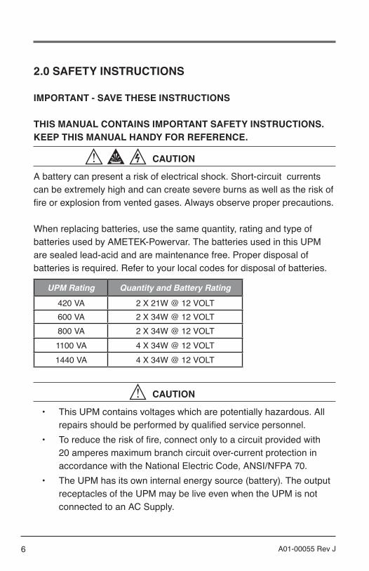
A battery can present a risk of electrical shock. Short-circuit currents can be extremely high and can create severe burns as well as the risk of fire or explosion from vented gases. Always observe proper precautions.
When replacing batteries, use the same quantity, rating and type of batteries used by AMETEK-Powervar. The batteries used in this UPM are sealed lead-acid and are maintenance free. Proper disposal of batteries is required. Refer to your local codes for disposal of batteries.
UPM Rating Quantity and Battery Rating
420 VA 2 X 21W @ 12 VOLT600 VA 2 X 34W @ 12 VOLT800 VA 2 X 34W @ 12 VOLT1100 VA 4 X 34W @ 12 VOLT1440 VA 4 X 34W @ 12 VOLT
CAUTION
• This UPM contains voltages which are potentially hazardous. All repairs should be performed by qualified service personnel.
• To reduce the risk of fire, connect only to a circuit provided with 20 amperes maximum branch circuit over-current protection in accordance with the National Electric Code, ANSI/NFPA 70.
• The UPM has its own internal energy source (battery). The output receptacles of the UPM may be live even when the UPM is not connected to an AC Supply.
7A01-00055 Rev J
Statement of Intended use
The medical UPMs are intended to protect medical, non-medical computer equipment and medical devices that need battery backup, surge protection, voltage regulation and line noise filtering in and around patient care areas. Safe and continuous operation of the UPM depends partially on the care taken by users. Please observe the following precautions. Not following these could result in warranty being voided.
NOTE:• The UPM is intended for stationary use.• This UPM is intended for patient vicinity. POWERVAR products
are not designed for use in any application intended to support or sustain life.
• Do not use this UPM for life support applications in which a malfunction or failure of the UPM system could cause failure or significantly alter the performance of a life-support device.
• Do not use this UPM near or around flammable gases. Do not use this UPM within oxygen-enriched atmospheres.
• Do not disassemble the UPM.• UPM is CLASS 1 equipment.• Do not attempt to power the UPM from any receptacle except a
properly grounded receptacle that matches the input plug provided with the UPM.
• Do not place the UPM near water or in environments of excessive humidity.
• Do not allow liquid or any foreign object to get inside the UPM.• Do not block air vents on the side of the UPM. Keep a minimum of
3 inches on all sides.• Do not plug appliances such as hair dryers, fans, heaters, etc. into
the UPM.• Do not place the UPM under direct sunshine or close to heat
emitting sources (excessively warm temperatures will shorten battery life).
• This UPM is intended for installation in a temperature controlled,
8 A01-00055 Rev J
indoor area free of conductive contaminants.• The AC power source for the UPM should be conveniently near the
UPM and easily accessible – avoid extension cords or temporary power strips to power the UPM.
• The total leakage current of the UPM and consumer connected equipment should not exceed 3.5 mA for non-medical units.
• Not for use in a computer room as defined in the Standard for the Protection of Electronic Computer/Data Processing Equipment, ANSI/NFPA 75.
• The socket-outlet shall be installed near the equipment and shall be easily accessible.
• The battery should be disconnected from the UPM by unplugging at its quick connectors when maintenance or service work inside the UPM is necessary.
• Do not dispose of batteries in a fire – batteries may explode.• Do not open or mutilate batteries. Doing so may release electrolyte
or other toxic substances, which may be harmful to the skin, eyes, or the environment.
A battery can present a risk of electric shock and high short circuit current. The following precautions should be observed when working with batteries:
• Remove watches, rings, or any other metal jewelry or objects which may make contact with the battery.
• Use tools with insulated handles.
FCC Issues
Attention
This UPM has been tested and found to comply with the limits for a Class A digital devices (Class B compliance optional), pursuant to Part 15 of the FCC rules. These limits are designed to provide reasonable protection against harmful interference in both residential and commercial environments.

9A01-00055 Rev J
This equipment generates, uses and can radiate radio frequency energy and if not installed and used in accordance with the instructions, may cause harmful interference to radio communications. However, there is no guarantee that interference will not occur in a particular installation. If this equipment does cause harmful interference to radio and/or television reception, which can be determined by turning the UPM equipment on and off, the user is encouraged to try to correct the interference by one or more of the following measures: Relocate the UPM Relocate the load.
This device complies to Part 15 of the FCC Rules. Operation is subject to the following two conditions: (1) this device may not cause harmful interference and (2) this device must accept interference received, including interference that may cause undesired operation.

10 A01-00055 Rev J
3.0 INSTALLATION
Inspecting the UPMIf any equipment has been damaged during shipment, keep the shipping cartons and packing materials for the carrier or place of purchase and file a claim for shipping damage:
1. File with the carrier within 15 days of receipt of the equipment; 2. Send a copy of the damage claim within 15 days to your service
representative.
NOTE:Check the battery recharge date on the shipping carton label. If the date has passed and the batteries were never recharged, do not use the UPM. Contact your service representative.
11A01-00055 Rev J
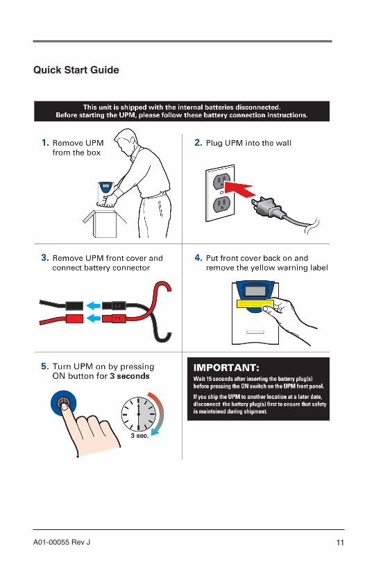
Quick Start Guide

12 A01-00055 Rev J
Unpacking the UPM
CAUTION
• Unpacking the unit in a low-temperature environment may cause condensation to occur in and on the unit. Do not install the unit until the inside and outside of the unit are absolutely dry {hazard of electric shock}.
• The unit is heavy. Use caution when unpacking and moving the unit.
Use care when moving and opening the carton. Leave the components packaged until ready to install.
To unpack the unit and accessories:1. Open the outer carton and remove the accessories packaged
with the unit.2. Carefully lift the unit out of the outer carton.3. Store the carton for future use.
Place the unit in a protected area that has adequate airflow and is free of humidity, flammable gas and corrosion.
NOTE:Before installation, please read and understand the following instructions. Carefully examine the carton for damage. Notify the carrier immediately if damage is observed. Be sure to save the carton should you ever need to ship the UPM for repair or maintenance.
This UPM is intended for indoor use only. Although your UPM is very rugged, its internal components are not sealed from the environment. The UPM must be installed in a protected environment away from heat producing appliances such as furnaces, radiators, and heaters. Protect the UPM from exposure to dripping or standing water and high humidity or condensing air conditions.

13A01-00055 Rev J
The location should provide adequate airflow around the UPM. Provide a minimum 3” clearance on all sides for proper ventilation.
Applying Power to the UPMConnect the power cord to a verified grounded 3 wire receptacle. Verify that the Site Wiring Fault “SF” is off (120 VAC models only). Once properly connected and initially checked, turn on the UPM by pressing and holding the front panel On/Off switch for 3 seconds.
Operational TestsObserve the front panel of the UPM. The following table shows system status behavior.
UPM LED DISPLAY UNIT STATUS UPM output on
Battery charge status in 20% increments
UPM load status in 20% increments
UPM in battery operation due to improper incoming AC voltage
UPM overloaded
Battery fault or battery disconnected
Unit in buck operation do to high incoming AC voltage
Unit in boost operation due to low incoming AC voltage
Fault
UPM over temperature.
UPM Front Panel
14 A01-00055 Rev J
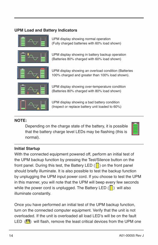
UPM Load and Battery Indicators
UPM display showing normal operation (Fully charged batteries with 60% load shown)
UPM display showing in battery backup operation (Batteries 80% charged with 60% load shown)
UPM display showing an overload condition (Batteries 100% charged and greater than 100% load shown).
UPM display showing over-temperature condition (Batteries 80% charged with 80% load shown)
UPM display showing a bad battery condition (Inspect or replace battery unit loaded to 60%)
NOTE:Depending on the charge state of the battery, it is possible that the battery charge level LEDs may be flashing (this is normal).
Initial StartupWith the connected equipment powered off, perform an initial test of the UPM backup function by pressing the Test/Silence button on the front panel. During this test, the Battery LED ( ) on the front panel should briefly illuminate. It is also possible to test the backup function by unplugging the UPM input power cord. If you choose to test the UPM in this manner, you will note that the UPM will beep every few seconds while the power cord is unplugged. The Battery LED ( ) will also illuminate constantly.
Once you have performed an initial test of the UPM backup function, turn on the connected computer equipment. Verify that the unit is not overloaded. If the unit is overloaded all load LED’s will be on the fault LED ( ) will flash, remove the least critical devices from the UPM one
15A01-00055 Rev J
by one until the overload LED is extinguished. With the connected loads powered up, perform the backup test once again by pressing the Test/Silence button or unplugging the UPM. When this final test is completed, the UPM will be ready to use.
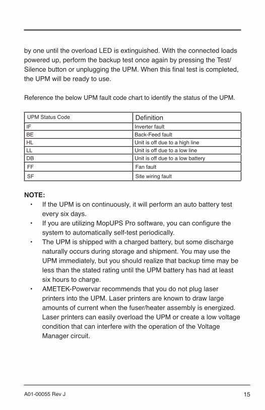
Reference the below UPM fault code chart to identify the status of the UPM.
UPM Status Code DefinitionIF Inverter faultBE Back-Feed faultHL Unit is off due to a high lineLL Unit is off due to a low lineDB Unit is off due to a low batteryFF Fan faultSF Site wiring fault
NOTE:• If the UPM is on continuously, it will perform an auto battery test
every six days.• If you are utilizing MopUPS Pro software, you can configure the
system to automatically self-test periodically.• The UPM is shipped with a charged battery, but some discharge
naturally occurs during storage and shipment. You may use the UPM immediately, but you should realize that backup time may be less than the stated rating until the UPM battery has had at least six hours to charge.
• AMETEK-Powervar recommends that you do not plug laser printers into the UPM. Laser printers are known to draw large amounts of current when the fuser/heater assembly is energized. Laser printers can easily overload the UPM or create a low voltage condition that can interfere with the operation of the Voltage Manager circuit.

16 A01-00055 Rev J
4.0 OPERATION
NOTE:In order to operate the UPM, you must first plug the battery enable plug(s) into the battery enable socket(s) behind the front panel of the UPM.
On/Off ButtonThe On/Off button is a dual function control:
• When the UPM is off and AC power is present to the UPM input, pressing the On/Off button for more than 2 seconds will turn the UPM output on.
• If battery is connected, pressing the On/Off switch for 2 seconds or more will “cold-start” the UPM on its internal battery with no incoming AC present.
• When the UPM is on, pressing the On/Off button for more than 2 seconds will turn off the UPM output power.
Test/Silence ButtonThe Test/Silence button is a dual function control:
• Pressing the Test/Silence button when AC power is present and the UPM is operating causes the UPM to enter a self test mode in which it tests both battery and inverter for a few seconds before returning to the AC supply. We recommend you close all open files before initiating self-test.

17A01-00055 Rev J
• When AC power fails, the UPM warns you with an audible alarm. The Test/Silence button is used to silence the alarm. When battery power begins to run low, the audible alarm will automatically return and beep at a faster rate.
Load MonitorThe Load Monitor is a six-segment LED display that shows the current load percentage. The first 5 LED’s each indicate approximately 20% load, with the 6th red LED showing the UPM is overloaded.
Battery Charge MonitorThe Battery Charge Monitor is a five-segment LED display that shows the charge capacity of the internal battery from zero to 100%. Each LED indicates approximately 20% of full charge.
Site Wiring Fault Indicator – (120 VAC models only)The SF symbol will be displayed on the front panel of the UPM if it is connected to an improperly wired AC receptacle. This is to indicate a missing safety ground wire or a reversal in phase and neutral wiring. If the “SF” is displayed on the front panel you should contact a qualified electrician immediately.
NOTE:Do not operate the UPM if the Site Wiring Fault LED is illuminated. When lit, the LED is indicating a wiring condition, which may represent a hazard of fire or electrocution. In addition, improper wiring may create reliability problems for both the UPM and the connected system. Never use a 3-blade to 2-blade adapter (often called a “cheater”) to power UPM. These devices remove the safety ground connection to the UPM and will cause the Site Wiring Fault LED to illuminate.

18 A01-00055 Rev J
MopUPS ProThe AMETEK-Powervar smart communications give you several options for:
• Protecting data on a computer powered UPM when battery runs low • Monitoring UPM to allow analysis of site power history and UPM
health.
A DB9 port provides a standard basic-signal interface that works with legacy and open source UPS monitoring software to trigger automated computer shutdown on low battery conditions.
The smart USB port links your UPM Series directly in to Windows, Linux or MAC OS as an HID device -- without need for additional USB device drivers. Use native OS Power Management utilities for automatic safe shutdown on low battery.
If you want added functionality including; data and event logging, auto- run command files before shutdown, access to UPM configuration and integrated network agent for central monitoring via AMETEK-Powervar ManageUPS® CIO Server software, download and use AMETEK-Powervar software MopUPS® Pro (for Window and Linux)
Communication Manager PortCommunication Manager provides a connection point on the rear panel of the UPM (both DB9 and USB ports). Connecting to this port and installing MopUPS Pro software package (optional) will allow you control over important UPM functions and access to operating information from the UPM. Using software, you can view such parameters as AC input and output voltage, power line frequency and battery voltage.
To support these functions without the MopUPS Pro software suite, you will need to either buy or build your own special cable. The following table describes the pin assignment of the DB9 connector on the rear of the UPM. Contact your computer supplier to determine the connection

19A01-00055 Rev J
configuration and connector style necessary to attach the cable to the computer.
DB-9 Definition for UPMPin Description1 Low Batt - RS232 Level2 RS232 RX3 RS232 TX4 Inverter Shutdown during AC Fail5 Ground6 AC Fail - RS232 Level7 AC Fail - Simulated NO Contact (programmable)8 Low Batt - Simulated NO Contact (programmable)9 Simulated Contact Ground
NOTE: Pin 5 should only be connected to ground.
NOTE:You may, of course, connect your computer to the UPM without using software. When power is lost, the UPM will beep and you will have to manually shut down the computer and UPM.
Start ManagerWhen AC power is not available, such as in a new installation where wiring may be incomplete, you can still start the UPM to test its operation and the operation of your system using Start Manager. With the UPM off, follow these simple steps:
1. Disconnect the input AC power cable from the AC mains.2. Ensure that the batteries are connected behind the front panel.3. Press and hold the On/Off switch on the front panel until the UPM
beeps.4. The UPM is now running on battery. When you have finished,
press the On/Off switch again. Plug the input AC power cable into the rear panel of the UPM.
20 A01-00055 Rev J
5.0 MAINTENANCE
Storage The UPM may be stored for extended periods in an environment that does not subject the UPM to extremes of temperature or humidity. When storing for extended periods, the battery should be charged every six months. If the storage location is characterized by above normal temperature, the battery should be recharged every two months. The UPM does not need to be turned on for charging to occur – it only needs to be plugged in with batteries connected.
NOTE: This product is not designed for continuous use on batteries.
Attention
Important InformationThe batteries inside this UPM are a special type called “sealed lead-acid”. These batteries use a non-liquid electrolyte, which makes it possible to use them in any physical orientation. The batteries are designed to last from two to five years. Their actual life span will depend on several factors including how often power outages occur, how long power outages last, and the temperature of the environment in which the UPM operates. Frequent, long duration power outages will shorten battery life more than infrequent, short duration outages. Consistent high temperatures in the area where the UPM is used will also shorten battery life.
The UPM is equipped with a Low/Replace Battery LED ( ) on the front panel. If the LED illuminates, you should make sure that the battery has at least six hours to charge without a power interruption. Inadequate (much shorter than usual) backup time, premature low battery alarm sounds, and persistent Low/Replace Battery LED illumination are all

21A01-00055 Rev J
good signs that the batteries inside your UPM requires replacement. The batteries inside your UPM are designed to be replaced by an authorized service personnel only. Please familiarize yourself with the following precautions before proceeding with battery replacement.
WARNING
Servicing of batteries should always be performed or supervised by someone who has read and understood the following precautions and who understands the hazards associated with storage batteries. This procedure should not be performed by someone who is unauthorized or who is incapable of following these precautions.
CAUTION
• Only the battery assembly in this unit is user serviceable (non-medical units only). The battery compartment is accessed by removing the front panel as described in the following instructions. No other user serviceable parts are contained in this UPM. Do not remove any cover other than the front battery access panels.
• A battery (even a depleted one) can deliver very high currents when short-circuited. There is a danger of electrical shock. Remove all watches, rings, bracelets or other metal objects. Use only tools with insulated handles.
• Do not dispose of batteries in a fire. There is a danger of explosion. • Do not dispose of batteries in an environmentally unfriendly
manner. Batteries may be returned to AMETEK-Powervar for proper disposal.
• Do not open or mutilate the batteries. This may release electrolyte that is toxic to the environment and harmful to the skin and eyes.
• Replacement batteries may be ordered from AMETEK-Powervar by phone or via our website at www.powervar.com. If purchasing batteries from another source, be sure to use the type and quantity of batteries.
• Medical units have no user serviceable parts inside.

22 A01-00055 Rev J
User Replaceable Battery (Non-medical units only)Eventually every UPM requires a new battery. AMETEK-Powervar expects the battery in your UPM to last a minimum of two years – perhaps longer if power outages are short and infrequent. The UPM makes battery replacement by the user fast and easy. It is not necessary to turn off the UPM or the connected system. The UPM allows the battery to be “hot-swapped” while the system is running.
NOTE: Changing the batteries in this UPM is designed to be a safe and simple procedure. Batteries may be replaced while the UPM is on and providing power to the connected load. You should remember, however, that if a power outage occurs after the old batteries are disconnected and before the new batteries are installed, power will be lost to your connected system and components.
CAUTION
RISK OF EXPLOSION IF BATTERY IS REPLACED BY INCORRECT TYPE.
When replacing batteries, contact Powervar for correct battery replacement kits. Reference replacemen kit part numbers below.
VA Rating Replacement Battery Kit Part No.
420 50842-01600/800 50880-01
1100/1440 50814-01
23A01-00055 Rev J
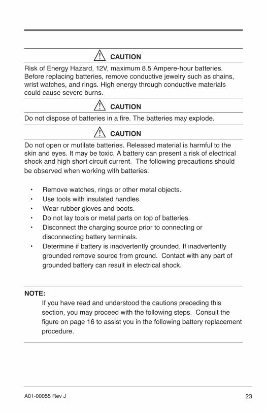
CAUTIONRisk of Energy Hazard, 12V, maximum 8.5 Ampere-hour batteries. Before replacing batteries, remove conductive jewelry such as chains, wrist watches, and rings. High energy through conductive materials could cause severe burns.
CAUTIONDo not dispose of batteries in a fire. The batteries may explode.
CAUTIONDo not open or mutilate batteries. Released material is harmful to the skin and eyes. It may be toxic. A battery can present a risk of electrical shock and high short circuit current. The following precautions should be observed when working with batteries:
• Remove watches, rings or other metal objects.• Use tools with insulated handles. • Wear rubber gloves and boots. • Do not lay tools or metal parts on top of batteries. • Disconnect the charging source prior to connecting or
disconnecting battery terminals.• Determine if battery is inadvertently grounded. If inadvertently
grounded remove source from ground. Contact with any part of grounded battery can result in electrical shock.
NOTE: If you have read and understood the cautions preceding this section, you may proceed with the following steps. Consult the figure on page 16 to assist you in the following battery replacement procedure.
24 A01-00055 Rev J
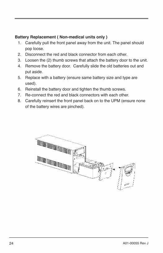
Battery Replacement ( Non-medical units only )1. Carefully pull the front panel away from the unit. The panel should
pop loose. 2. Disconnect the red and black connector from each other. 3. Loosen the (2) thumb screws that attach the battery door to the unit. 4. Remove the battery door. Carefully slide the old batteries out and
put aside. 5. Replace with a battery (ensure same battery size and type are
used). 6. Reinstall the battery door and tighten the thumb screws. 7. Re-connect the red and black connectors with each other. 8. Carefully reinsert the front panel back on to the UPM (ensure none
of the battery wires are pinched).

25A01-00055 Rev J
6.0 SPECIFICATIONSNorth American Models ABCE422-11 and ABCE422-11MED
ABCE422-11 ABCE422-11MED
Type Standard Medical Grade
Power Rating (VA/Watts) 420 / 378 420 / 378
Inverter Waveform Low Distortion Sine Wave Low Distortion Sine Wave
Transfer Time 4 ms. Typical 4 ms. Typical
Frequency 60 Hz. 60 Hz.
BTU/Hr. 140 140
T.H.D. w/100% Resistive Load <4% On Battery <4% On Battery
Online Efficiency (w/o Charger) 90% 90%
Input Voltage 120 120
Input Current 4.50 Amps 4.50 Amps
Output Voltage 120 120
Output Current (VA/Watts) 3.50 / 3.15 Amps 3.50 / 3.15 Amps
Input Voltage Range (w/o Using Battery)
96 to 144 Volts 96 to 144 Volts
Output Regulation (On Mains) ± 10% ± 10%
Output Regulation (On Battery) ± 5% ± 5%
Backup Time at Full Load (0.7 P.F.)
5 Minutes 5 Minutes
Floor Mountable Yes (Optional) Yes (Optional)
Communications Interface DB9, USB DB9, USB
Shipping Weight (lbs.) 37 37

26 A01-00055 Rev J
Front Panel Controls • Power On/Off • Test • Load Level LED Gauge • Battery Charge LED Gauge • Voltage Manager Boost LED • Voltage Output On LED • Voltage Manager Buck LED • On Battery LED • Replace Battery LED • Overload LED • Fault Code LED • System Over Temperature LED
Rear Panel Information and Controls • Six (6) Foot Power Cord with NEMA 5-15P Plug• Four (4) NEMA 5-15R Receptacles• Configuration Manager DIP Switches• Communications Manager DB9 Port, USB Port• Circuit Breaker• AC Inlet Module
Internal Batteries • User Hot-Swappable (See Instruction Manual) • Type: 12 Volt, High Rate 21W • Quantity: 2 Batteries • Recharge Time: 6 Hours to 80%, 24 Hours to Full Charge
Environmental • Temperature: 0 to 40℃ (32 to 104℉) Operating
-20 to 60℃ (-40 to 140℉) Shipment/Storage • Humidity: 5 to 90% Non-Condensing (Operating,
Shipment/Storage) • Altitude: 3,000m (10,000 ft) max. Operating;
12,000m (40,000 ft) max. Shipment/Storage
Safety Agency and EMC Compliance: All Units are Listed by UL and Marked With the UL/cUL Marking
Standard UPM: Products Listed to:
• UL1778 5th Edition• CSA 22.2 Nos. 107.3-14
Products in Compliance with: • FCC-Part 15, Subpart B, Sections 15.107b & 15.109b
Class A Digital Device*• CISPR11:2009, A1; 2010, Class A*• IEC61000-4-2, Electrostatic Discharge• IEC61000-4-3, Radiated Electromagnetic Field Immunity• IEC61000-4-4, Electrical Fast Transient/Burst Immunity• IEC61000-4-5, Surge Immunity• IEC61000-4-6, Immunity to Conducted Radio Frequency
Disturbances• IEC61000-4-8, Power Frequency Magnetic Field Immunity• IEC61000-4-11, Voltage Dips, Short Interruptions and
Voltage Variations
Medical UPM: Products Listed to:
• UL60601-1 2nd and 3rd Edition• UL1778 5th Edition• CSA 22.2 No. 601.1-M89• CSA 22.2 No. 107-1-M91• CSA 22.2 Nos. 0-M1982• CSA 22.2 Nos. 0.4-M1982
Products in Compliance with: • FCC-Part 15, Subpart B, Sections 15.107b & 15.109b
Class A Digital Device* • CISPR11:2009, A1; 2010, Class A* • EN60601-1-2 : 2007
*Note: Class B is Available as an OptionPlease Consult Your Powervar Sales Representative
RoHS Compliance: All Products (Standard and Medical) are RoHS Compliant
North American Models ABCE422-11 and ABCE422-11MED
Warranty/Support: POWERVAR warrants the electronics and transformers used in its uninterruptible power managers to be free from defects in materials and workmanship for a period of five years from the date of shipment. Batteries are warranted for a period of two years from the date of shipment. For service or support on any POWERVAR product, please contact POWERVAR Technical Support at (800) 369-7179 or visit the POWERVAR website at www.powervar.com.
Battery Life Disclaimer: POWERVAR’s standard battery warranty applies only to UPS and UPM products which are continuously connected to AC mains power, except during utility power outages. Products which are regularly and inten-tionally disconnected from AC mains power will experience battery discharge/charge cycles potentially far more numerous than those for which the battery was designed. As a result, products used in such applications will experience substantial-ly reduced battery life. For that reason, POWERVAR’s standard battery warranty does not apply for applications in which the UPS or UPM product is regularly and intentionally disconnected from AC mains power. POWERVAR UPS and UPM products used in such applications shall receive a 90 day warranty on batteries.
NOISE REJECTION-ISOLATION: With unit under power and an ANSI/IEEE C62.41Cat. A pulse applied either normal or common mode at the input, the noise output voltage will be less than 10V normal mode and less than 0.5V common mode in all four quadrants (CM-NM, NM-NM, CM-CM, NM-COM).
SURGE VOLTAGE WITHSTAND CAPABILITY: Tested under power to ANSI/IEEE C62.41 Cat. A & B (formerly IEEEE587-1980). CAT. A - 6000V @ 200 amps, 0.5 usec risetime, 100 kHZ decay, Cat. B - 6000V @ 500 amps, 0.5 usec risetime, 100 kHZ decay.
27A01-00055 Rev J
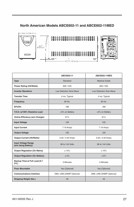
North American Models ABCE602-11 and ABCE602-11MED
ABCE602-11 ABCE602-11MED
Type Standard Medical Grade
Power Rating (VA/Watts) 600 / 540 600 / 540
Inverter Waveform Low Distortion Sine Wave Low Distortion Sine Wave
Transfer Time 4 ms. Typical 4 ms. Typical
Frequency 60 Hz. 60 Hz.
BTU/Hr. 189 189
T.H.D. w/100% Resistive Load <4% on Battery <4% on Battery
Online Efficiency (w/o Charger) 91% 91%
Input Voltage 120 120
Input Current 7.16 Amps 7.16 Amps
Output Voltage 120 120
Output Current (VA/Watts) 5.00 / 4.50 Amps 5.00 / 4.50 Amps
Input Voltage Range (w/o Using Battery) 96 to 144 Volts 96 to 144 Volts
Output Regulation (On Mains) ± 10% ± 10%
Output Regulation (On Battery) ± 5% ± 5%
Backup Time at Full Load (0.7 P.F.) 5 Minutes 5 Minutes
Floor Mountable Yes (Optional) Yes (Optional)
Communications Interface DB9, USB (SNMP Optional) DB9, USB (SNMP Optional)
Shipping Weight (lbs.) 45 45

28 A01-00055 Rev J
Front Panel Controls • Power On/Off • Test • Load Level LED Gauge • Battery Charge LED Gauge • Voltage Manager Boost LED • Voltage Output On LED • Voltage Manager Buck LED • On Battery LED • Replace Battery LED • Overload LED • Fault Code LED • System Over Temperature LED
Rear Panel Information and Controls • Six (6) Foot Power Cord with NEMA 5-15P Plug• Six (6) NEMA 5-15R Receptacles• Configuration Manager DIP Switches• Communications Manager DB9 Port, USB Port• Circuit Breaker• AC Inlet Module• SNMP Slot (Contact Factory)
Internal Batteries • User Hot-Swappable (See Instruction Manual) • Type: 12 Volt, High Rate 34W • Quantity: 2 Batteries • Recharge Time: 6 Hours to 80%, 24 Hours to Full Charge
Environmental • Temperature: 0 to 40℃ (32 to 104℉) Operating
-20 to 60℃ (-40 to 140℉) Shipment/Storage • Humidity: 5 to 90% Non-Condensing (Operating,
Shipment/Storage) • Altitude: 3,000m (10,000 ft) max. Operating;
12,000m (40,000 ft) max. Shipment/Storage
Safety Agency and EMC Compliance: All Units are Listed by UL and Marked with the UL/cUL Marking
Standard UPM: Products Listed to:
• UL1778 5th Edition• CSA 22.2 Nos. 107.3-14
Products in Compliance with: • FCC-Part 15, Subpart B, Sections 15.107b & 15.109b
Class A Digital Device*• CISPR11:2009, A1; 2010, Class A*• IEC61000-4-2, Electrostatic Discharge• IEC61000-4-3, Radiated Electromagnetic Field Immunity• IEC61000-4-4, Electrical Fast Transient/Burst Immunity• IEC61000-4-5, Surge Immunity• IEC61000-4-6, Immunity to Conducted Radio Frequency
Disturbances• IEC61000-4-8, Power Frequency Magnetic Field Immunity• IEC61000-4-11, Voltage Dips, Short Interruptions and
Voltage Variations
Medical UPM: Products Listed to:
• UL60601-1 2nd and 3rd Edition• UL1778 5th Edition• CSA 22.2 No. 601.1-M89• CSA 22.2 No. 107-1-M91• CSA 22.2 Nos. 0-M1982• CSA 22.2 Nos. 0.4-M1982
Products in Compliance with: • FCC-Part 15, Subpart B, Sections 15.107b & 15.109b
Class A Digital Device* • CISPR11:2009, A1; 2010, Class A* • EN60601-1-2 : 2007
*Note: Class B is Available as an Option Please Consult Your Powervar Sales Representative
RoHS Compliance: All products (Standard and Medical) are RoHS Compliant
North American Models ABCE602-11 and ABCE602-11MED
Warranty/Support: POWERVAR warrants the electronics and transformers used in its uninterruptible power managers to be free from defects in materials and workmanship for a period of five years from the date of shipment. Batteries are warranted for a period of two years from the date of shipment. For service or support on any POWERVAR product, please contact POWERVAR Technical Support at (800) 369-7179 or visit the POWERVAR website at www.powervar.com.
Battery Life Disclaimer: POWERVAR’s standard battery warranty applies only to UPS and UPM products which are continuously connected to AC mains power, except during utility power outages. Products which are regularly and inten-tionally disconnected from AC mains power will experience battery discharge/charge cycles potentially far more numerous than those for which the battery was designed. As a result, products used in such applications will experience substantial-ly reduced battery life. For that reason, POWERVAR’s standard battery warranty does not apply for applications in which the UPS or UPM product is regularly and intentionally disconnected from AC mains power. POWERVAR UPS and UPM products used in such applications shall receive a 90 day warranty on batteries.
NOISE REJECTION-ISOLATION: With unit under power and an ANSI/IEEE C62.41Cat. A pulse applied either normal or common mode at the input, the noise output voltage will be less than 10V normal mode and less than 0.5V common mode in all four quadrants (CM-NM, NM-NM, CM-CM, NM-COM).
SURGE VOLTAGE WITHSTAND CAPABILITY: Tested under power to ANSI/IEEE C62.41 Cat. A & B (formerly IEEEE587-1980). CAT. A - 6000V @ 200 amps, 0.5 usec risetime, 100 kHZ decay, Cat. B - 6000V @ 500 amps, 0.5 usec risetime, 100 kHZ decay.
29A01-00055 Rev J
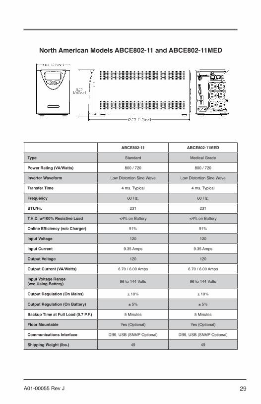
North American Models ABCE802-11 and ABCE802-11MED
ABCE802-11 ABCE802-11MED
Type Standard Medical Grade
Power Rating (VA/Watts) 800 / 720 800 / 720
Inverter Waveform Low Distortion Sine Wave Low Distortion Sine Wave
Transfer Time 4 ms. Typical 4 ms. Typical
Frequency 60 Hz. 60 Hz.
BTU/Hr. 231 231
T.H.D. w/100% Resistive Load <4% on Battery <4% on Battery
Online Efficiency (w/o Charger) 91% 91%
Input Voltage 120 120
Input Current 9.35 Amps 9.35 Amps
Output Voltage 120 120
Output Current (VA/Watts) 6.70 / 6.00 Amps 6.70 / 6.00 Amps
Input Voltage Range (w/o Using Battery) 96 to 144 Volts 96 to 144 Volts
Output Regulation (On Mains) ± 10% ± 10%
Output Regulation (On Battery) ± 5% ± 5%
Backup Time at Full Load (0.7 P.F.) 5 Minutes 5 Minutes
Floor Mountable Yes (Optional) Yes (Optional)
Communications Interface DB9, USB (SNMP Optional) DB9, USB (SNMP Optional)
Shipping Weight (lbs.) 49 49

30 A01-00055 Rev J
Front Panel Controls • Power On/Off • Test • Load Level LED Gauge • Battery Charge LED Gauge • Voltage Manager Boost LED • Voltage Output On LED • Voltage Manager Buck LED • On Battery LED • Replace Battery LED • Overload LED • Fault Code LED • System Over Temperature LED
Rear Panel Information and Controls • Six (6) Foot Power Cord with NEMA 5-15P Plug• Six (6) NEMA 5-15R Receptacles• Configuration Manager DIP Switches• Communications Manager DB9 Port, USB Port• Circuit Breaker• AC Inlet Module• SNMP Slot (Contact Factory)
Internal Batteries • User Hot-Swappable (See Instruction Manual) • Type: 12 Volt, High Rate 34W • Quantity: 2 Batteries • Recharge Time: 6 Hours to 80%, 24 Hours to Full Charge
Environmental • Temperature: 0 to 40℃ (32 to 104℉) Operating
-20 to 60℃ (-40 to 140℉) Shipment/Storage • Humidity: 5 to 90% Non-Condensing (Operating,
Shipment/Storage) • Altitude: 3,000m (10,000 ft) max. Operating;
12,000m (40,000 ft) max. Shipment/Storage
Safety Agency and EMC Compliance: All Units are Listed by UL and Marked with the UL/cUL Marking
Standard UPM: Products Listed to:
• UL1778 5th Edition• CSA 22.2 Nos. 107.3-14
Products in Compliance with: • FCC-Part 15, Subpart B, Sections 15.107b & 15.109b
Class A Digital Device*• CISPR11:2009, A1; 2010, Class A*• IEC61000-4-2, Electrostatic Discharge• IEC61000-4-3, Radiated Electromagnetic Field Immunity• IEC61000-4-4, Electrical Fast Transient/Burst Immunity• IEC61000-4-5, Surge Immunity• IEC61000-4-6, Immunity to Conducted Radio Frequency
Disturbances• IEC61000-4-8, Power Frequency Magnetic Field Immunity• IEC61000-4-11, Voltage Dips, Short Interruptions and
Voltage Variations
Medical UPM: Products Listed to:
• UL60601-1 2nd and 3rd Edition• UL1778 5th Edition• CSA 22.2 No. 601.1-M89• CSA 22.2 No. 107-1-M91• CSA 22.2 Nos. 0-M1982• CSA 22.2 Nos. 0.4-M1982
Products in Compliance with: • FCC-Part 15, Subpart B, Sections 15.107b & 15.109b
Class A Digital Device* • CISPR11:2009, A1; 2010, Class A* • EN60601-1-2 : 2007
*Note: Class B is Available as an OptionPlease Consult Your Powervar Sales Representative
RoHS Compliance: All products (Standard and Medical) are RoHS Compliant
North American Models ABCE802-11 and ABCE802-11MED
Warranty/Support: POWERVAR warrants the electronics and transformers used in its uninterruptible power managers to be free from defects in materials and workmanship for a period of five years from the date of shipment. Batteries are warranted for a period of two years from the date of shipment. For service or support on any POWERVAR product, please contact POWERVAR Technical Support at (800) 369-7179 or visit the POWERVAR website at www.powervar.com.
Battery Life Disclaimer: POWERVAR’s standard battery warranty applies only to UPS and UPM products which are continuously connected to AC mains power, except during utility power outages. Products which are regularly and inten-tionally disconnected from AC mains power will experience battery discharge/charge cycles potentially far more numerous than those for which the battery was designed. As a result, products used in such applications will experience substantial-ly reduced battery life. For that reason, POWERVAR’s standard battery warranty does not apply for applications in which the UPS or UPM product is regularly and intentionally disconnected from AC mains power. POWERVAR UPS and UPM products used in such applications shall receive a 90 day warranty on batteries.
NOISE REJECTION-ISOLATION: With unit under power and an ANSI/IEEE C62.41Cat. A pulse applied either normal or common mode at the input, the noise output voltage will be less than 10V normal mode and less than 0.5V common mode in all four quadrants (CM-NM, NM-NM, CM-CM, NM-COM).
SURGE VOLTAGE WITHSTAND CAPABILITY: Tested under power to ANSI/IEEE C62.41 Cat. A & B (formerly IEEEE587-1980). CAT. A - 6000V @ 200 amps, 0.5 usec risetime, 100 kHZ decay, Cat. B - 6000V @ 500 amps, 0.5 usec risetime, 100 kHZ decay.
31A01-00055 Rev J
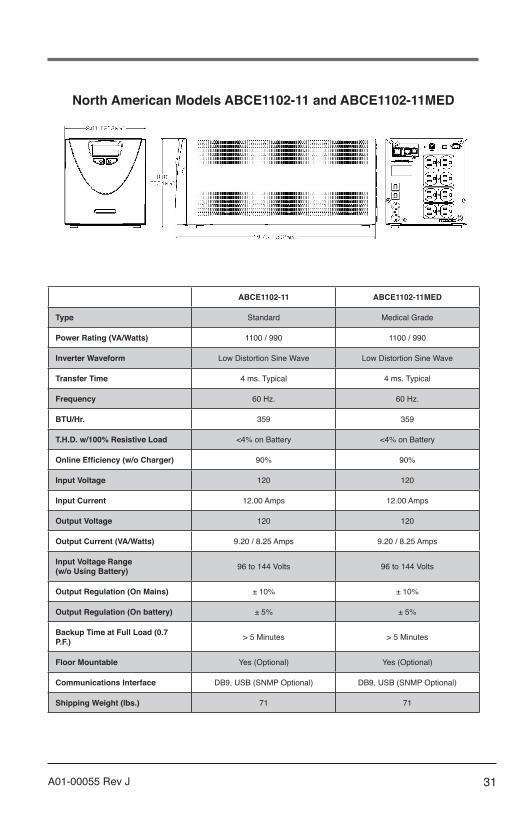
North American Models ABCE1102-11 and ABCE1102-11MED
ABCE1102-11 ABCE1102-11MED
Type Standard Medical Grade
Power Rating (VA/Watts) 1100 / 990 1100 / 990
Inverter Waveform Low Distortion Sine Wave Low Distortion Sine Wave
Transfer Time 4 ms. Typical 4 ms. Typical
Frequency 60 Hz. 60 Hz.
BTU/Hr. 359 359
T.H.D. w/100% Resistive Load <4% on Battery <4% on Battery
Online Efficiency (w/o Charger) 90% 90%
Input Voltage 120 120
Input Current 12.00 Amps 12.00 Amps
Output Voltage 120 120
Output Current (VA/Watts) 9.20 / 8.25 Amps 9.20 / 8.25 Amps
Input Voltage Range (w/o Using Battery) 96 to 144 Volts 96 to 144 Volts
Output Regulation (On Mains) ± 10% ± 10%
Output Regulation (On battery) ± 5% ± 5%
Backup Time at Full Load (0.7 P.F.) > 5 Minutes > 5 Minutes
Floor Mountable Yes (Optional) Yes (Optional)
Communications Interface DB9, USB (SNMP Optional) DB9, USB (SNMP Optional)
Shipping Weight (lbs.) 71 71

32 A01-00055 Rev J
Front Panel Controls • Power On/Off • Test • Load Level LED Gauge • Battery Charge LED Gauge • Voltage Manager Boost LED • Voltage Output On LED • Voltage Manager Buck LED • On Battery LED • Replace Battery LED • Overload LED • Fault Code LED • System Over Temperature LED
Rear Panel Information and Controls • Six (6) Foot Power Cord with NEMA 5-15P Plug• Eight (8) NEMA 5-15R Receptacles• Configuration Manager DIP Switches• Communications Manager DB9 Port, USB Port• Circuit Breaker• AC Inlet Module• SNMP Slot (Contact Factory)
Internal Batteries • User Hot-Swappable (See Instruction Manual) • Type: 12 Volt, High Rate 34W • Quantity: 4 Batteries • Recharge Time: 8 Hours to 80%, 24 Hours to Full Charge
Environmental • Temperature: 0 to 40℃ (32 to 104℉) Operating
-20 to 60℃ (-40 to 140℉) Shipment/Storage • Humidity: 5 to 90% Non-Condensing (Operating,
Shipment/Storage) • Altitude: 3,000m (10,000 ft) max. Operating;
12,000m (40,000 ft) max. Shipment/Storage
Safety Agency and EMC Compliance: All Units are Listed by UL and Marked with the UL/cUL Marking
Standard UPM: Products Listed to:
• UL1778 5th Edition• CSA 22.2 Nos. 107.3-14
Products in Compliance with: • FCC-Part 15, Subpart B, Sections 15.107b & 15.109b
Class A Digital Device*• CISPR11:2009, A1; 2010, Class A*• IEC61000-4-2, Electrostatic Discharge• IEC61000-4-3, Radiated Electromagnetic Field Immunity• IEC61000-4-4, Electrical Fast Transient/Burst Immunity• IEC61000-4-5, Surge Immunity• IEC61000-4-6, Immunity to Conducted Radio Frequency
Disturbances• IEC61000-4-8, Power Frequency Magnetic Field Immunity• IEC61000-4-11, Voltage Dips, Short Interruptions and
Voltage Variations
Medical UPM: Products Listed to:
• UL60601-1 2nd and 3rd Edition• UL1778 5th Edition• CSA 22.2 No. 601.1-M89• CSA 22.2 No. 107-1-M91• CSA 22.2 Nos. 0-M1982• CSA 22.2 Nos. 0.4-M1982
Products in Compliance with: • FCC-Part 15, Subpart B, Sections 15.107b & 15.109b
Class A Digital Device* • CISPR11:2009, A1; 2010, Class A* • EN60601-1-2 : 2007
*Note: Class B is Available as an OptionPlease Consult Your Powervar Sales Representative
RoHS Compliance: All products (Standard and Medical) are RoHS Compliant
North American Models ABCE1102-11 and ABCE1102-11MED
Warranty/Support: POWERVAR warrants the electronics and transformers used in its uninterruptible power managers to be free from defects in materials and workmanship for a period of five years from the date of shipment. Batteries are warranted for a period of two years from the date of shipment. For service or support on any POWERVAR product, please contact POWERVAR Technical Support at (800) 369-7179 or visit the POWERVAR website at www.powervar.com.
Battery Life Disclaimer: POWERVAR’s standard battery warranty applies only to UPS and UPM products which are continuously connected to AC mains power, except during utility power outages. Products which are regularly and inten-tionally disconnected from AC mains power will experience battery discharge/charge cycles potentially far more numerous than those for which the battery was designed. As a result, products used in such applications will experience substantial-ly reduced battery life. For that reason, POWERVAR’s standard battery warranty does not apply for applications in which the UPS or UPM product is regularly and intentionally disconnected from AC mains power. POWERVAR UPS and UPM products used in such applications shall receive a 90 day warranty on batteries.
NOISE REJECTION-ISOLATION: With unit under power and an ANSI/IEEE C62.41Cat. A pulse applied either normal or common mode at the input, the noise output voltage will be less than 10V normal mode and less than 0.5V common mode in all four quadrants (CM-NM, NM-NM, CM-CM, NM-COM).
SURGE VOLTAGE WITHSTAND CAPABILITY: Tested under power to ANSI/IEEE C62.41 Cat. A & B (formerly IEEEE587-1980). CAT. A - 6000V @ 200 amps, 0.5 usec risetime, 100 kHZ decay, Cat. B - 6000V @ 500 amps, 0.5 usec risetime, 100 kHZ decay.

33A01-00055 Rev J
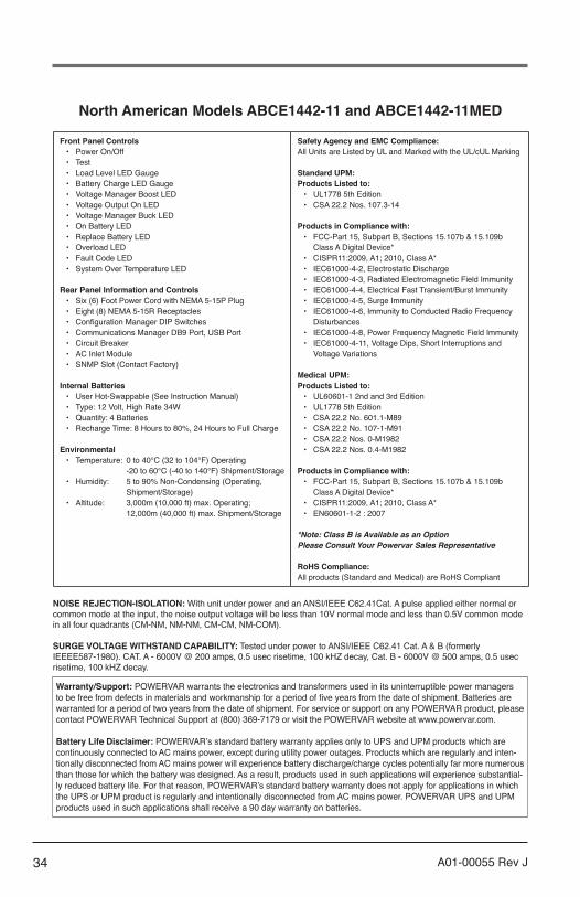
North American Models ABCE1442-11 and ABCE1442-11MED
ABCE1442-11 ABCE1442-11MED
Type Standard Medical Grade
Power Rating (VA/Watts) 1440 / 1296 1440 / 1296
Inverter Waveform Low Distortion Sine Wave Low Distortion Sine Wave
Transfer Time 4 ms. Typical 4 ms. Typical
Frequency 60 Hz. 60 Hz.
BTU/Hr. 459 459
T.H.D. w/100% Resistive Load <4% on Battery <4% on Battery
Online Efficiency (w/o Charger) 91% 91%
Input Voltage 120 120
Input Current 12.00 Amps 12.00 Amps
Output Voltage 120 120
Output Current (VA/Watts) 12.00 / 10.80 Amps 12.00 / 10.80 Amps
Input Voltage Range (w/o Using Battery) 96 to 144 Volts 96 to 144 Volts
Output Regulation (On Mains) ± 10% ± 10%
Output Regulation (On battery) ± 5% ± 5%
Backup Time at Full Load (0.7 P.F.) > 5 Minutes > 5 Minutes
Floor Mountable Yes (Optional) Yes (Optional)
Communications Interface DB9, USB (SNMP Optional) DB9, USB (SNMP Optional)
Shipping Weight (lbs.) 71 71
34 A01-00055 Rev J
Front Panel Controls • Power On/Off • Test • Load Level LED Gauge • Battery Charge LED Gauge • Voltage Manager Boost LED • Voltage Output On LED • Voltage Manager Buck LED • On Battery LED • Replace Battery LED • Overload LED • Fault Code LED • System Over Temperature LED
Rear Panel Information and Controls • Six (6) Foot Power Cord with NEMA 5-15P Plug• Eight (8) NEMA 5-15R Receptacles• Configuration Manager DIP Switches• Communications Manager DB9 Port, USB Port• Circuit Breaker• AC Inlet Module• SNMP Slot (Contact Factory)
Internal Batteries • User Hot-Swappable (See Instruction Manual) • Type: 12 Volt, High Rate 34W • Quantity: 4 Batteries • Recharge Time: 8 Hours to 80%, 24 Hours to Full Charge
Environmental • Temperature: 0 to 40℃ (32 to 104℉) Operating
-20 to 60℃ (-40 to 140℉) Shipment/Storage • Humidity: 5 to 90% Non-Condensing (Operating,
Shipment/Storage) • Altitude: 3,000m (10,000 ft) max. Operating;
12,000m (40,000 ft) max. Shipment/Storage
Safety Agency and EMC Compliance: All Units are Listed by UL and Marked with the UL/cUL Marking
Standard UPM: Products Listed to:
• UL1778 5th Edition• CSA 22.2 Nos. 107.3-14
Products in Compliance with: • FCC-Part 15, Subpart B, Sections 15.107b & 15.109b
Class A Digital Device*• CISPR11:2009, A1; 2010, Class A*• IEC61000-4-2, Electrostatic Discharge• IEC61000-4-3, Radiated Electromagnetic Field Immunity• IEC61000-4-4, Electrical Fast Transient/Burst Immunity• IEC61000-4-5, Surge Immunity• IEC61000-4-6, Immunity to Conducted Radio Frequency
Disturbances• IEC61000-4-8, Power Frequency Magnetic Field Immunity• IEC61000-4-11, Voltage Dips, Short Interruptions and
Voltage Variations
Medical UPM: Products Listed to:
• UL60601-1 2nd and 3rd Edition• UL1778 5th Edition• CSA 22.2 No. 601.1-M89• CSA 22.2 No. 107-1-M91• CSA 22.2 Nos. 0-M1982• CSA 22.2 Nos. 0.4-M1982
Products in Compliance with: • FCC-Part 15, Subpart B, Sections 15.107b & 15.109b
Class A Digital Device* • CISPR11:2009, A1; 2010, Class A* • EN60601-1-2 : 2007
*Note: Class B is Available as an OptionPlease Consult Your Powervar Sales Representative
RoHS Compliance: All products (Standard and Medical) are RoHS Compliant
North American Models ABCE1442-11 and ABCE1442-11MED
Warranty/Support: POWERVAR warrants the electronics and transformers used in its uninterruptible power managers to be free from defects in materials and workmanship for a period of five years from the date of shipment. Batteries are warranted for a period of two years from the date of shipment. For service or support on any POWERVAR product, please contact POWERVAR Technical Support at (800) 369-7179 or visit the POWERVAR website at www.powervar.com.
Battery Life Disclaimer: POWERVAR’s standard battery warranty applies only to UPS and UPM products which are continuously connected to AC mains power, except during utility power outages. Products which are regularly and inten-tionally disconnected from AC mains power will experience battery discharge/charge cycles potentially far more numerous than those for which the battery was designed. As a result, products used in such applications will experience substantial-ly reduced battery life. For that reason, POWERVAR’s standard battery warranty does not apply for applications in which the UPS or UPM product is regularly and intentionally disconnected from AC mains power. POWERVAR UPS and UPM products used in such applications shall receive a 90 day warranty on batteries.
NOISE REJECTION-ISOLATION: With unit under power and an ANSI/IEEE C62.41Cat. A pulse applied either normal or common mode at the input, the noise output voltage will be less than 10V normal mode and less than 0.5V common mode in all four quadrants (CM-NM, NM-NM, CM-CM, NM-COM).
SURGE VOLTAGE WITHSTAND CAPABILITY: Tested under power to ANSI/IEEE C62.41 Cat. A & B (formerly IEEEE587-1980). CAT. A - 6000V @ 200 amps, 0.5 usec risetime, 100 kHZ decay, Cat. B - 6000V @ 500 amps, 0.5 usec risetime, 100 kHZ decay.

35A01-00055 Rev J
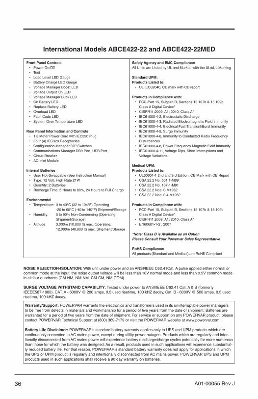
International Models ABCE422-22 and ABCE422-22MED
ABCE422-22 ABCE422-22MED
Type Standard Medical Grade
Power Rating (VA/Watts) 420 / 378 420 / 378
Inverter Waveform Low Distortion Sine Wave Low Distortion Sine Wave
Transfer Time 4 ms. Typical 4 ms. Typical
Frequency 50 / 60 Hz. 50 / 60 Hz.
BTU/Hr. 140 140
T.H.D. w/100% Resistive Load <4% On Battery <4% On Battery
Online Efficiency (w/o Charger) 90% 90%
Input Voltage 230 230
Input Current 2.70 Amps 2.70 Amps
Output Voltage 230 230
Output Current (VA/Watts) 1.85 / 1.65 Amps 1.85 / 1.65 Amps
Input Voltage Range (w/o Using Battery) 185 to 276 Volts 185 to 276 Volts
Output Regulation (On Mains) ± 10% ± 10%
Output Regulation (On Battery) ± 5% ± 5%
Backup Time at Full Load (0.7 P.F.) 5 Minutes 5 Minutes
Floor Mountable Yes (Optional) Yes (Optional)
Communications Interface DB9, USB DB9, USB
Shipping Weight (kg) 16.80 16.80
36 A01-00055 Rev J
Front Panel Controls • Power On/Off • Test • Load Level LED Gauge • Battery Charge LED Gauge • Voltage Manager Boost LED • Voltage Output On LED • Voltage Manager Buck LED • On Battery LED • Replace Battery LED • Overload LED • Fault Code LED • System Over Temperature LED
Rear Panel Information and Controls • 1.8 Meter Power Cord with IEC320 Plug • Four (4) IEC320 Receptacles • Configuration Manager DIP Switches • Communications Manager DB9 Port, USB Port • Circuit Breaker • AC Inlet Module
Internal Batteries • User Hot-Swappable (See Instruction Manual) • Type: 12 Volt, High Rate 21W • Quantity: 2 Batteries • Recharge Time: 6 Hours to 80%, 24 Hours to Full Charge
Environmental • Temperature: 0 to 40℃ (32 to 104℉) Operating
-20 to 60℃ (-40 to 140℉) Shipment/Storage • Humidity: 5 to 90% Non-Condensing (Operating,
Shipment/Storage) • Altitude: 3,000m (10,000 ft) max. Operating;
12,000m (40,000 ft) max. Shipment/Storage
Safety Agency and EMC Compliance: All Units are Listed by UL and Marked with the UL/cUL Marking
Standard UPM: Products Listed to:
• UL IEC62040, CE mark with CB report
Products in Compliance with: • FCC-Part 15, Subpart B, Sections 15.107b & 15.109b
Class A Digital Device*• CISPR11:2009, A1; 2010, Class A*• IEC61000-4-2, Electrostatic Discharge• IEC61000-4-3, Radiated Electromagnetic Field Immunity• IEC61000-4-4, Electrical Fast Transient/Burst Immunity• IEC61000-4-5, Surge Immunity• IEC61000-4-6, Immunity to Conducted Radio Frequency
Disturbances• IEC61000-4-8, Power Frequency Magnetic Field Immunity• IEC61000-4-11, Voltage Dips, Short Interruptions and
Voltage Variations
Medical UPM: Products Listed to:
• UL60601-1 2nd and 3rd Edition, CE Mark with CB Report • CSA 22.2 No. 601.1-M89 • CSA 22.2 No. 107-1-M91 • CSA 22.2 Nos. 0-M1982 • CSA 22.2 Nos. 0.4-M1982
Products in Compliance with: • FCC-Part 15, Subpart B, Sections 15.107b & 15.109b
Class A Digital Device* • CISPR11:2009, A1; 2010, Class A* • EN60601-1-2 : 2007
*Note: Class B is Available as an OptionPlease Consult Your Powervar Sales Representative
RoHS Compliance: All products (Standard and Medical) are RoHS Compliant
International Models ABCE422-22 and ABCE422-22MED
Warranty/Support: POWERVAR warrants the electronics and transformers used in its uninterruptible power managers to be free from defects in materials and workmanship for a period of five years from the date of shipment. Batteries are warranted for a period of two years from the date of shipment. For service or support on any POWERVAR product, please contact POWERVAR Technical Support at (800) 369-7179 or visit the POWERVAR website at www.powervar.com.
Battery Life Disclaimer: POWERVAR’s standard battery warranty applies only to UPS and UPM products which are continuously connected to AC mains power, except during utility power outages. Products which are regularly and inten-tionally disconnected from AC mains power will experience battery discharge/charge cycles potentially far more numerous than those for which the battery was designed. As a result, products used in such applications will experience substantial-ly reduced battery life. For that reason, POWERVAR’s standard battery warranty does not apply for applications in which the UPS or UPM product is regularly and intentionally disconnected from AC mains power. POWERVAR UPS and UPM products used in such applications shall receive a 90 day warranty on batteries.
NOISE REJECTION-ISOLATION: With unit under power and an ANSI/IEEE C62.41Cat. A pulse applied either normal or common mode at the input, the noise output voltage will be less than 10V normal mode and less than 0.5V common mode in all four quadrants (CM-NM, NM-NM, CM-CM, NM-COM).
SURGE VOLTAGE WITHSTAND CAPABILITY: Tested under power to ANSI/IEEE C62.41 Cat. A & B (formerly IEEEE587-1980). CAT. A - 6000V @ 200 amps, 0.5 usec risetime, 100 kHZ decay, Cat. B - 6000V @ 500 amps, 0.5 usec risetime, 100 kHZ decay.

37A01-00055 Rev J
International Models ABCE602-22 and ABCE602-22MED
ABCE602-22 ABCE602-22MED
Type Standard Medical Grade
Power Rating (VA/Watts) 600 / 540 600 / 540
Inverter Waveform Low Distortion Sine Wave Low Distortion Sine Wave
Transfer Time 4 ms. Typical 4 ms. Typical
Frequency 50 / 60 Hz. 50 / 60 Hz.
BTU/Hr. 162 162
T.H.D. w/100% Resistive Load <4% on Battery <4% on Battery
Online Efficiency (w/o Charger) 92% 92%
Input Voltage 230 230
Input Current 3.73 Amps 3.73 Amps
Output Voltage 230 230
Output Current (VA/Watts) 2.60 / 2.35 Amps 2.60 / 2.35 Amps
Input Voltage Range (w/o Using Battery) 185 to 276 Volts 185 to 276 Volts
Output Regulation (On Mains) ± 10% ± 10%
Output Regulation (On Battery) ± 5% ± 5%
Backup Time at Full Load (0.7 P.F.) 5 Minutes 5 Minutes
Floor Mountable Yes (Optional) Yes (Optional)
Communications Interface DB9, USB (SNMP Optional) DB9, USB (SNMP Optional)
Shipping Weight (kg) 20.40 20.40

38 A01-00055 Rev J
Front Panel Controls • Power On/Off • Test • Load Level LED Gauge • Battery Charge LED Gauge • Voltage Manager Boost LED • Voltage Output On LED • Voltage Manager Buck LED • On Battery LED • Replace Battery LED • Overload LED • Fault Code LED • System Over Temperature LED
Rear Panel Information and Controls • 1.8 Meter Power Cord with IEC320 Plug • Eight (8) IEC320 Receptacles • Configuration Manager DIP Switches • Communications Manager DB9 Port, USB Port • Circuit Breaker • AC Inlet Module • SNMP Slot (Contact Factory)
Internal Batteries • User Hot-Swappable (See Instruction Manual) • Type: 12 Volt, High Rate 34W • Quantity: 2 Batteries • Recharge Time: 6 Hours to 80%, 24 Hours to Full Charge
Environmental • Temperature: 0 to 40℃ (32 to 104℉) Operating
-20 to 60℃ (-40 to 140℉) Shipment/Storage • Humidity: 5 to 90% Non-Condensing (Operating,
Shipment/Storage) • Altitude: 3,000m (10,000 ft) max. Operating;
12,000m (40,000 ft) max. Shipment/Storage
Safety Agency and EMC Compliance: All Units are Listed by UL and Marked with the UL/cUL Marking
Standard UPM: Products Listed to:
• UL IEC62040, CE Mark with CB Report
Products in Compliance with: • FCC-Part 15, Subpart B, Sections 15.107b & 15.109b
Class A Digital Device*• CISPR11:2009, A1; 2010, Class A*• IEC61000-4-2, Electrostatic Discharge• IEC61000-4-3, Radiated Electromagnetic Field Immunity• IEC61000-4-4, Electrical Fast Transient/Burst Immunity• IEC61000-4-5, Surge Immunity• IEC61000-4-6, Immunity to Conducted Radio Frequency
Disturbances• IEC61000-4-8, Power Frequency Magnetic Field Immunity• IEC61000-4-11, Voltage Dips, Short Interruptions and
Voltage Variations
Medical UPM: Products Listed to:
• UL60601-1 2nd and 3rd Edition, CE Mark with CB Report • CSA 22.2 No. 601.1-M89 • CSA 22.2 No. 107-1-M91 • CSA 22.2 Nos. 0-M1982 • CSA 22.2 Nos. 0.4-M1982
Products in Compliance With: • FCC-Part 15, Subpart B, Sections 15.107b & 15.109b
Class A Digital Device* • CISPR11:2009, A1; 2010, Class A* • EN60601-1-2 : 2007
*Note: Class B is Available as an OptionPlease Consult Your Powervar Sales Representative
RoHS Compliance: All products (Standard and Medical) are RoHS Compliant
International Models ABCE602-22 and ABCE602-22MED
Warranty/Support: POWERVAR warrants the electronics and transformers used in its uninterruptible power managers to be free from defects in materials and workmanship for a period of five years from the date of shipment. Batteries are warranted for a period of two years from the date of shipment. For service or support on any POWERVAR product, please contact POWERVAR Technical Support at (800) 369-7179 or visit the POWERVAR website at www.powervar.com.
Battery Life Disclaimer: POWERVAR’s standard battery warranty applies only to UPS and UPM products which are continuously connected to AC mains power, except during utility power outages. Products which are regularly and inten-tionally disconnected from AC mains power will experience battery discharge/charge cycles potentially far more numerous than those for which the battery was designed. As a result, products used in such applications will experience substantial-ly reduced battery life. For that reason, POWERVAR’s standard battery warranty does not apply for applications in which the UPS or UPM product is regularly and intentionally disconnected from AC mains power. POWERVAR UPS and UPM products used in such applications shall receive a 90 day warranty on batteries.
NOISE REJECTION-ISOLATION: With unit under power and an ANSI/IEEE C62.41Cat. A pulse applied either normal or common mode at the input, the noise output voltage will be less than 10V normal mode and less than 0.5V common mode in all four quadrants (CM-NM, NM-NM, CM-CM, NM-COM).
SURGE VOLTAGE WITHSTAND CAPABILITY: Tested under power to ANSI/IEEE C62.41 Cat. A & B (formerly IEEEE587-1980). CAT. A - 6000V @ 200 amps, 0.5 usec risetime, 100 kHZ decay, Cat. B - 6000V @ 500 amps, 0.5 usec risetime, 100 kHZ decay.

39A01-00055 Rev J
International Models ABCE802-22 and ABCE802-22MED
ABCE802-22 ABCE802-22MED
Type Standard Medical Grade
Power Rating (VA/Watts) 800 / 720 800 / 720
Inverter Waveform Low Distortion Sine Wave Low Distortion Sine Wave
Transfer Time 4 ms. Typical 4 ms. Typical
Frequency 50 / 60 Hz. 50 / 60 Hz.
BTU/Hr. 199 199
T.H.D. w/100% Resistive Load <4% on Battery <4% on Battery
Online Efficiency (w/o Charger) 92% 92%
Input Voltage 230 230
Input Current 4.88 Amps 4.88 Amps
Output Voltage 230 230
Output Current (VA/Watts) 3.50 / 3.15 Amps 3.50 / 3.15 Amps
Input Voltage Range (w/o Using Battery) 185 to 276 Volts 185 to 276 Volts
Output Regulation (On Mains) ± 10% ± 10%
Output Regulation (On Battery) ± 5% ± 5%
Backup Time at Full Load (0.7 P.F.) 5 Minutes 5 Minutes
Floor Mountable Yes (Optional) Yes (Optional)
Communications Interface DB9, USB (SNMP Optional) DB9, USB (SNMP Optional)
Shipping Weight (kg) 22 22

40 A01-00055 Rev J
Front Panel Controls • Power On/Off • Test • Load Level LED Gauge • Battery Charge LED Gauge • Voltage Manager Boost LED • Voltage Output On LED • Voltage Manager Buck LED • On Battery LED • Replace Battery LED • Overload LED • Fault Code LED • System Over Temperature LED
Rear Panel Information and Controls • 1.8 Meter Power Cord with IEC320 Plug • Six (6) IEC320 Receptacles • Configuration Manager DIP Switches • Communications Manager DB9 Port, USB Port • Circuit Breaker • AC Inlet Module • SNMP Slot (Contact Factory)
Internal Batteries • User Hot-Swappable (See Instruction Manual) • Type: 12 Volt, High Rate 34W • Quantity: 2 Batteries • Recharge Time: 6 Hours to 80%, 24 Hours to Full Charge
Environmental • Temperature: 0 to 40℃ (32 to 104℉) Operating
-20 to 60℃ (-40 to 140℉) Shipment/Storage • Humidity: 5 to 90% Non-Condensing (Operating,
Shipment/Storage) • Altitude: 3,000m (10,000 ft) max. Operating;
12,000m (40,000 ft) max. Shipment/Storage
Safety Agency and EMC Compliance: All Units are Listed by UL and Marked with the UL/cUL Marking
Standard UPM: Products Listed to:
• UL IEC62040, CE Mark with CB report
Products in Compliance with: • FCC-Part 15, Subpart B, Sections 15.107b & 15.109b
Class A Digital Device* • CISPR11:2009, A1; 2010, Class A* • IEC61000-4-2, Electrostatic Discharge • IEC61000-4-3, Radiated Electromagnetic Field Immunity • IEC61000-4-4, Electrical Fast Transient/Burst Immunity • IEC61000-4-5, Surge Immunity • IEC61000-4-6, Immunity to Conducted Radio Frequency Disturbances • IEC61000-4-8, Power Frequency Magnetic Field Immunity • IEC61000-4-11, Voltage Dips, Short Interruptions and
Voltage Variations
Medical UPM: Products Listed to:
• UL60601-1 2nd and 3rd Edition, CE Mark with CB Report • CSA 22.2 No. 601.1-M89 • CSA 22.2 No. 107-1-M91 • CSA 22.2 Nos. 0-M1982 • CSA 22.2 Nos. 0.4-M1982
Products in Compliance with: • FCC-Part 15, Subpart B, Sections 15.107b & 15.109b
Class A Digital Device* • CISPR11:2009, A1; 2010, Class A* • EN60601-1-2 : 2007
*Note: Class B is Available as an OptionPlease Consult Your Powervar Sales Representative
RoHS Compliance: All products (Standard and Medical) are RoHS Compliant
International Models ABCE802-22 and ABCE802-22MED
Warranty/Support: POWERVAR warrants the electronics and transformers used in its uninterruptible power managers to be free from defects in materials and workmanship for a period of five years from the date of shipment. Batteries are warranted for a period of two years from the date of shipment. For service or support on any POWERVAR product, please contact POWERVAR Technical Support at (800) 369-7179 or visit the POWERVAR website at www.powervar.com.
Battery Life Disclaimer: POWERVAR’s standard battery warranty applies only to UPS and UPM products which are continuously connected to AC mains power, except during utility power outages. Products which are regularly and inten-tionally disconnected from AC mains power will experience battery discharge/charge cycles potentially far more numerous than those for which the battery was designed. As a result, products used in such applications will experience substantial-ly reduced battery life. For that reason, POWERVAR’s standard battery warranty does not apply for applications in which the UPS or UPM product is regularly and intentionally disconnected from AC mains power. POWERVAR UPS and UPM products used in such applications shall receive a 90 day warranty on batteries.
NOISE REJECTION-ISOLATION: With unit under power and an ANSI/IEEE C62.41Cat. A pulse applied either normal or common mode at the input, the noise output voltage will be less than 10V normal mode and less than 0.5V common mode in all four quadrants (CM-NM, NM-NM, CM-CM, NM-COM).
SURGE VOLTAGE WITHSTAND CAPABILITY: Tested under power to ANSI/IEEE C62.41 Cat. A & B (formerly IEEEE587-1980). CAT. A - 6000V @ 200 amps, 0.5 usec risetime, 100 kHZ decay, Cat. B - 6000V @ 500 amps, 0.5 usec risetime, 100 kHZ decay.
41A01-00055 Rev J
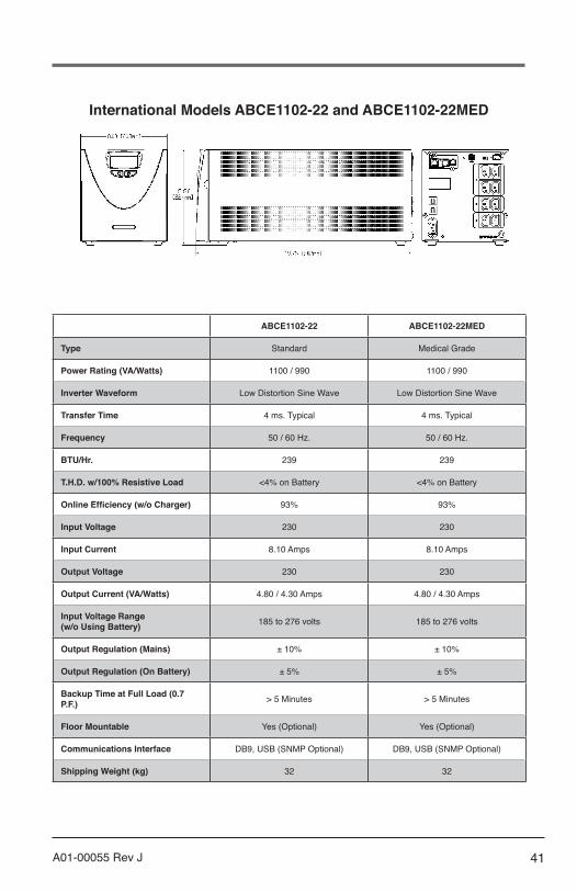
International Models ABCE1102-22 and ABCE1102-22MED
ABCE1102-22 ABCE1102-22MED
Type Standard Medical Grade
Power Rating (VA/Watts) 1100 / 990 1100 / 990
Inverter Waveform Low Distortion Sine Wave Low Distortion Sine Wave
Transfer Time 4 ms. Typical 4 ms. Typical
Frequency 50 / 60 Hz. 50 / 60 Hz.
BTU/Hr. 239 239
T.H.D. w/100% Resistive Load <4% on Battery <4% on Battery
Online Efficiency (w/o Charger) 93% 93%
Input Voltage 230 230
Input Current 8.10 Amps 8.10 Amps
Output Voltage 230 230
Output Current (VA/Watts) 4.80 / 4.30 Amps 4.80 / 4.30 Amps
Input Voltage Range (w/o Using Battery) 185 to 276 volts 185 to 276 volts
Output Regulation (Mains) ± 10% ± 10%
Output Regulation (On Battery) ± 5% ± 5%
Backup Time at Full Load (0.7 P.F.) > 5 Minutes > 5 Minutes
Floor Mountable Yes (Optional) Yes (Optional)
Communications Interface DB9, USB (SNMP Optional) DB9, USB (SNMP Optional)
Shipping Weight (kg) 32 32

42 A01-00055 Rev J
Front Panel Controls • Power On/Off • Test • Load Level LED Gauge • Battery Charge LED Gauge • Voltage Manager Boost LED • Voltage Output On LED • Voltage Manager Buck LED • On Battery LED • Replace Battery LED • Overload LED • Fault Code LED • System Over Temperature LED
Rear Panel Information and Controls • 1.8 Meter Power Cord with IEC320 Plug • Eight (8) IEC320 Receptacles • Configuration Manager DIP Switches • Communications Manager DB9 Port, USB Port • Circuit Breaker • AC Inlet Module • SNMP Slot (Contact Factory)
Internal Batteries • User Hot-Swappable (See Instruction Manual) • Type: 12 Volt, High Rate 34W • Quantity: 4 Batteries • Recharge Time: 8 Hours to 80%, 24 Hours to Full Charge
Environmental • Temperature: 0 to 40℃ (32 to 104℉) Operating
-20 to 60℃ (-40 to 140℉) Shipment/Storage • Humidity: 5 to 90% Non-Condensing (Operating,
Shipment/Storage) • Altitude: 3,000m (10,000 ft) max. Operating;
12,000m (40,000 ft) max. Shipment/Storage
Safety Agency and EMC Compliance: All Units are Listed by UL and Marked with the UL/cUL Marking
Standard UPM: Products Listed to:
• UL IEC62040, CE Mark with CB report
Products in Compliance with: • FCC-Part 15, Subpart B, Sections 15.107b & 15.109b
Class A Digital Device* • CISPR11:2009, A1; 2010, Class A* • IEC61000-4-2, Electrostatic Discharge • IEC61000-4-3, Radiated Electromagnetic Field Immunity • IEC61000-4-4, Electrical Fast Transient/Burst Immunity • IEC61000-4-5, Surge Immunity • IEC61000-4-6, Immunity to Conducted Radio Frequency Disturbances • IEC61000-4-8, Power Frequency Magnetic Field Immunity • IEC61000-4-11, Voltage Dips, Short Interruptions and
Voltage Variations
Medical UPM: Products Listed to:
• UL60601-1 2nd and 3rd Edition, CE Mark with CB Report • CSA 22.2 No. 601.1-M89 • CSA 22.2 No. 107-1-M91 • CSA 22.2 Nos. 0-M1982 • CSA 22.2 Nos. 0.4-M1982
Products in Compliance With: • FCC-Part 15, Subpart B, Sections 15.107b & 15.109b
Class A Digital Device* • CISPR11:2009, A1; 2010, Class A* • EN60601-1-2 : 2007
*Note: Class B is Available as an OptionPlease Consult Your Powervar Sales Representative
RoHS Compliance: All products (Standard and Medical) are RoHS Compliant
International Models ABCE1102-22 and ABCE1102-22MED
Warranty/Support: POWERVAR warrants the electronics and transformers used in its uninterruptible power managers to be free from defects in materials and workmanship for a period of five years from the date of shipment. Batteries are warranted for a period of two years from the date of shipment. For service or support on any POWERVAR product, please contact POWERVAR Technical Support at (800) 369-7179 or visit the POWERVAR website at www.powervar.com.
Battery Life Disclaimer: POWERVAR’s standard battery warranty applies only to UPS and UPM products which are continuously connected to AC mains power, except during utility power outages. Products which are regularly and inten-tionally disconnected from AC mains power will experience battery discharge/charge cycles potentially far more numerous than those for which the battery was designed. As a result, products used in such applications will experience substantial-ly reduced battery life. For that reason, POWERVAR’s standard battery warranty does not apply for applications in which the UPS or UPM product is regularly and intentionally disconnected from AC mains power. POWERVAR UPS and UPM products used in such applications shall receive a 90 day warranty on batteries.
NOISE REJECTION-ISOLATION: With unit under power and an ANSI/IEEE C62.41Cat. A pulse applied either normal or common mode at the input, the noise output voltage will be less than 10V normal mode and less than 0.5V common mode in all four quadrants (CM-NM, NM-NM, CM-CM, NM-COM).
SURGE VOLTAGE WITHSTAND CAPABILITY: Tested under power to ANSI/IEEE C62.41 Cat. A & B (formerly IEEEE587-1980). CAT. A - 6000V @ 200 amps, 0.5 usec risetime, 100 kHZ decay, Cat. B - 6000V @ 500 amps, 0.5 usec risetime, 100 kHZ decay.
43A01-00055 Rev J
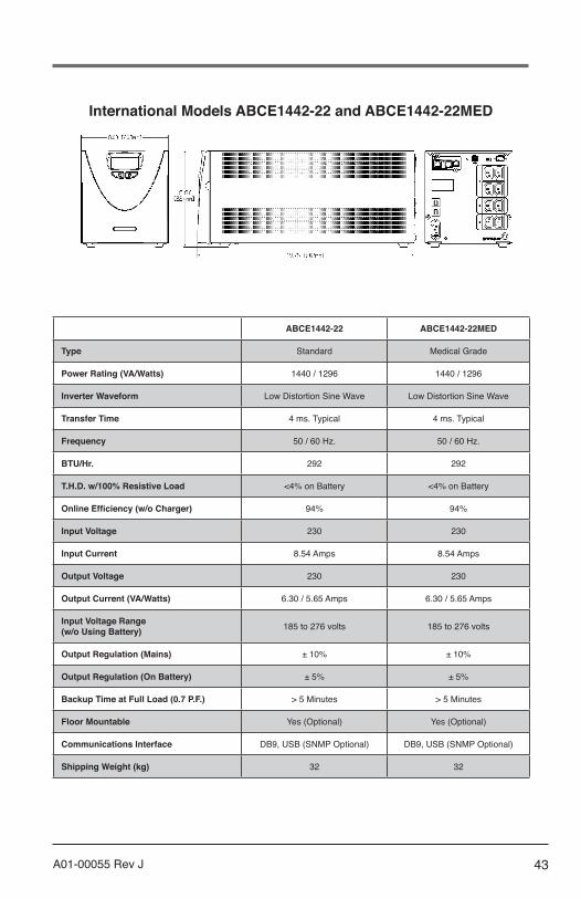
International Models ABCE1442-22 and ABCE1442-22MED
ABCE1442-22 ABCE1442-22MED
Type Standard Medical Grade
Power Rating (VA/Watts) 1440 / 1296 1440 / 1296
Inverter Waveform Low Distortion Sine Wave Low Distortion Sine Wave
Transfer Time 4 ms. Typical 4 ms. Typical
Frequency 50 / 60 Hz. 50 / 60 Hz.
BTU/Hr. 292 292
T.H.D. w/100% Resistive Load <4% on Battery <4% on Battery
Online Efficiency (w/o Charger) 94% 94%
Input Voltage 230 230
Input Current 8.54 Amps 8.54 Amps
Output Voltage 230 230
Output Current (VA/Watts) 6.30 / 5.65 Amps 6.30 / 5.65 Amps
Input Voltage Range (w/o Using Battery) 185 to 276 volts 185 to 276 volts
Output Regulation (Mains) ± 10% ± 10%
Output Regulation (On Battery) ± 5% ± 5%
Backup Time at Full Load (0.7 P.F.) > 5 Minutes > 5 Minutes
Floor Mountable Yes (Optional) Yes (Optional)
Communications Interface DB9, USB (SNMP Optional) DB9, USB (SNMP Optional)
Shipping Weight (kg) 32 32
44 A01-00055 Rev J
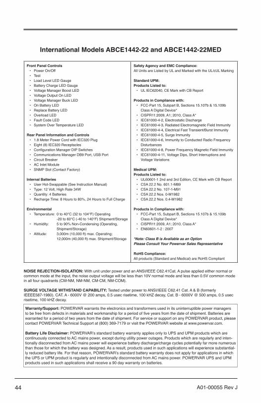
Front Panel Controls • Power On/Off • Test • Load Level LED Gauge • Battery Charge LED Gauge • Voltage Manager Boost LED • Voltage Output On LED • Voltage Manager Buck LED • On Battery LED • Replace Battery LED • Overload LED • Fault Code LED • System Over Temperature LED
Rear Panel Information and Controls • 1.8 Meter Power Cord with IEC320 Plug • Eight (8) IEC320 Receptacles • Configuration Manager DIP Switches • Communications Manager DB9 Port, USB Port • Circuit Breaker • AC Inlet Module • SNMP Slot (Contact Factory)
Internal Batteries • User Hot-Swappable (See Instruction Manual) • Type: 12 Volt, High Rate 34W • Quantity: 4 Batteries • Recharge Time: 8 Hours to 80%, 24 Hours to Full Charge
Environmental • Temperature: 0 to 40℃ (32 to 104℉) Operating
-20 to 60℃ (-40 to 140℉) Shipment/Storage • Humidity: 5 to 90% Non-Condensing (Operating,
Shipment/Storage) • Altitude: 3,000m (10,000 ft) max. Operating;
12,000m (40,000 ft) max. Shipment/Storage
Safety Agency and EMC Compliance: All Units are Listed by UL and Marked with the UL/cUL Marking
Standard UPM: Products Listed to:
• UL IEC62040, CE Mark with CB Report
Products in Compliance with: • FCC-Part 15, Subpart B, Sections 15.107b & 15.109b
Class A Digital Device* • CISPR11:2009, A1; 2010, Class A* • IEC61000-4-2, Electrostatic Discharge • IEC61000-4-3, Radiated Electromagnetic Field Immunity • IEC61000-4-4, Electrical Fast Transient/Burst Immunity • IEC61000-4-5, Surge Immunity • IEC61000-4-6, Immunity to Conducted Radio Frequency Disturbances • IEC61000-4-8, Power Frequency Magnetic Field Immunity • IEC61000-4-11, Voltage Dips, Short Interruptions and
Voltage Variations
Medical UPM: Products Listed to:
• UL60601-1 2nd and 3rd Edition, CE Mark with CB Report • CSA 22.2 No. 601.1-M89 • CSA 22.2 No. 107-1-M91 • CSA 22.2 Nos. 0-M1982 • CSA 22.2 Nos. 0.4-M1982
Products in Compliance with: • FCC-Part 15, Subpart B, Sections 15.107b & 15.109b
Class A Digital Device* • CISPR11:2009, A1; 2010, Class A* • EN60601-1-2 : 2007
*Note: Class B is Available as an OptionPlease Consult Your Powervar Sales Representative
RoHS Compliance: All products (Standard and Medical) are RoHS Compliant
International Models ABCE1442-22 and ABCE1442-22MED
Warranty/Support: POWERVAR warrants the electronics and transformers used in its uninterruptible power managers to be free from defects in materials and workmanship for a period of five years from the date of shipment. Batteries are warranted for a period of two years from the date of shipment. For service or support on any POWERVAR product, please contact POWERVAR Technical Support at (800) 369-7179 or visit the POWERVAR website at www.powervar.com.
Battery Life Disclaimer: POWERVAR’s standard battery warranty applies only to UPS and UPM products which are continuously connected to AC mains power, except during utility power outages. Products which are regularly and inten-tionally disconnected from AC mains power will experience battery discharge/charge cycles potentially far more numerous than those for which the battery was designed. As a result, products used in such applications will experience substantial-ly reduced battery life. For that reason, POWERVAR’s standard battery warranty does not apply for applications in which the UPS or UPM product is regularly and intentionally disconnected from AC mains power. POWERVAR UPS and UPM products used in such applications shall receive a 90 day warranty on batteries.
NOISE REJECTION-ISOLATION: With unit under power and an ANSI/IEEE C62.41Cat. A pulse applied either normal or common mode at the input, the noise output voltage will be less than 10V normal mode and less than 0.5V common mode in all four quadrants (CM-NM, NM-NM, CM-CM, NM-COM).
SURGE VOLTAGE WITHSTAND CAPABILITY: Tested under power to ANSI/IEEE C62.41 Cat. A & B (formerly IEEEE587-1980). CAT. A - 6000V @ 200 amps, 0.5 usec risetime, 100 kHZ decay, Cat. B - 6000V @ 500 amps, 0.5 usec risetime, 100 kHZ decay.

45A01-00055 Rev J
7.0 TROUBLESHOOTING
The troubleshooting information provided in this section should help you discover the cause of most commonly encountered difficulties. Before following the troubleshooting steps provided, be certain that you have verified the following items:
• The UPM should be plugged into a properly working outlet.• The line voltage to the UPM is within specified boundaries.• The circuit breaker on the rear panel of the UPM has been reset.• The battery enable plug(s) is installed.
• Problem Possible Cause Action you should take
UPM does not power up and has no audible alarm
1. On/Off Button not pressed long enough2. No incoming line voltage or voltage too high or too low3. UPM input power cord is not plugged in4. Rear panel circuit breaker is tripped
1. Press and hold the On/Off switch for 3 seconds min.2. Check wall socket and test for proper line voltage.3. Plug in input power cord.4. Reduce load and reset circuit breaker.
UPM Overload LED’s are illuminated and continuous audible alarm sounds
UPM is overload Reduce load by removing the least critical load items from the UPM output.
Low/Replace Battery LED is illuminated
Battery voltage is too low or battery is dead
Recharge battery for at least six hours and reset UPM. If LED is still illuminated, replace the battery.
Site Wiring Fault LED is illuminated Site wiring problem Contact a qualified electrician to verify
wiring at this site.
Backup time is less than expected
Battery is not fully charged or battery is dead
Recharge battery for at least six hours and retest back up time.
UPM is normal, but the computer will not turn on.
Computer input power cord is loose or not connected Connect the power input power cord.
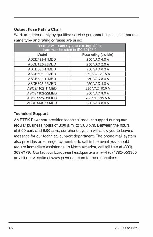
46 A01-00055 Rev J
Output Fuse Rating ChartWork to be done only by qualified service personnel. It is critical that the same type and rating of fuses are used:
Replace with same type and rating of fusefuse must be rated to IEC 60127-2
Model Fuse rating (slo-blo)ABCE422-11MED 250 VAC 4.0 AABCE422-22MED 250 VAC 2.0 AABCE602-11MED 250 VAC 6.3 AABCE602-22MED 250 VAC 3.15 AABCE802-11MED 250 VAC 8.0 AABCE802-22MED 250 VAC 4.0 AABCE1102-11MED 250 VAC 10.0 AABCE1102-22MED 250 VAC 8.0 AABCE1442-11MED 250 VAC 12.5 AABCE1442-22MED 250 VAC 8.0 A
Technical SupportAMETEK-Powervar provides technical product support during our regular business hours of 8:00 a.m. to 5:00 p.m. Between the hours of 5:00 p.m. and 8:00 a.m., our phone system will allow you to leave a message for our technical support department. The phone mail system also provides an emergency number to call in the event you should require immediate assistance. In North America, call toll free at (800) 369-7179. Contact our European headquarters at +44 (0) 1793-553980 or visit our website at www.powervar.com for more locations.

47A01-00055 Rev J
8.0 WARRANTY
The AMETEK-Powervar Security II Series UPM is warranted to be free from defects in material and workmanship for sixty (60) months from date of shipment from AMETEK-Powervar, on the chassis & electronic components and twenty four (24) months from date of shipment from AMETEK-Powervar on the batteries. This warranty is limited to repairing, replacing, or refurbishing, at AMETEK-Powervars option, any defective component, circuit board or module within the Product. This warranty is limited to AMETEK-Powervar depot service.
Life SupportAMETEK-Powervar does not recommend the use of our UPM products on life support equipment where the failure of the UPM could endanger or compromise patient safety or diminish the effectivenes of such life support equipment.

48 A01-00055 Rev J
AVIS IMPORTANT SUR LA GARANTIE DE LA BATTERIE
La politique de garantie énoncée à la section 8 n’est pas valide pour les applications où le gestionnaire d’alimentation sans interruption (UPM) est débranché régulièrement et intentionnellement dusecteur. La garantie de 2 ans offerte par AMETEK-Powervar pour les batteries ne s’applique qu’aux produits installés correctement et connectés constamment au secteur, sauf lors des pannes de courant.
Les produits débranchés régulièrement et intentionnellement du secteur verront la durée de vie de leur batterie réduite de façon notable. La clause de garantie standard d’AMETEK-Powervarne s’applique pas dans ces cas là et elle est remplacée par une garantie de 90 jours à partir de la date d’expédition d’AMETEK- Powervar. La garantie fournie par AMETEK-Powervar inclut le remplacement de la batterie ou des systèmes de batterie si les batteries ne répondent pas aux caractéristiques de performance telles que définies uniquement par AMETEK-Powervar.
9.0 FRENCH TRANSLATION

49A01-00055 Rev J
Danger - Le symbole danger est utilisé pour signaler les situations, emplacements et conditions qui, s’ils ne sont pas évités, CAUSERONT la mort, des blessures sérieuses et/ou des dommages matériels importants.
Attention - Le symbole attention est utilisé pour signaler les situations et les conditions potentiellement dangereuses qui, si elles ne sont pas évitées, peuvent causer des blessures. L’équipement peut aussi être endommagé.
Avertissement - Le symbole avertissement est utilisé pour signaler les situations et les conditions potentiellement dangereuses qui, si elles ne sont pas évitées, POURRAIENT causer des blessures sérieuses, voire mortelles. Des dommages matériels importants POURRAIENT aussi en résulter.
Prudence - Le symbole prudence est utilisé pour signaler les situations et les conditions qui peuvent causer des blessures à l’utilisateur et/ou endommager l’équipement.
D’autres symboles d’avertissement peuvent apparaîtreen plus des symboles Danger et Attention et sont utilisés pour identifier des dangers spéciaux. Ces avertissements concernent des domaines particuliers qui demandent une attention et/ou des procédures spéciales afin d’éviter des blessures importantes, voire la mort.
Avertissements électriques - Le symbole d’avertissement électrique est un éclair à l’intérieur d’un triangle. Le symbole d’avertissement électrique est utilisé pour signaler les emplacements et les conditions de haute tension, qui peuvent causer des blessures importantes, voire mortelles.
Avertissements d’explosion - Le symbole d’avertissement d’explosion est représenté par une explosion à l’intérieur d’un triangle. Le symbole d’avertissement d’explosion estutilisé pour signaler les emplacements et les conditions dans lesquels des pièces fondues explosives peuvent causer des blessures importantes, voire mortelles, si les précautions appropriées ne sont pas prises.
Courant alternatif
Voir le manuel/livret d’instructions.
DANGER
ATTENTION
AVERTISSEMENT
PRUDENCE
50 A01-00055 Rev J
1.0 INTRODUCTION
Nous vous remercions pour votre achat de l’AMETEK-Powervar Security II Series UPM (ci-après dénommé « UPM »). AMETEK-Powervar fabrique deux versions de l’UPM – une version standard, une versionmédicale répertoriée UL60601-1 et C22.2 No. 60601.1. En outre, tousles modèles sont compatibles avec les systèmes internationaux de distribution électrique. Les versions internationales sont homologuéesUL (version médicale homologuée IEC60601-1 et EN60601) et portent le marquage CE. Nous avons préparé ce document afin de vous familiariser avec les fonctions et les commandes de ce produit. Si, après examende ce manuel, vous avez des questions, n’hésitez pas à contacter notre équipe d’assistance technique par téléphone au (1-800-369-7179) ou nous écrire à [email protected]
AMETEK-Powervar est un fournisseur mondial de solutions de gestion de l’énergie, dont le siège est à Waukugan, Illinois, avec des ventes internationales et des bureaux de distribution à Swindon Royaume-Uni, Toronto Canada, Mexico Mexique et en Allemagne. Toutes les solutions d’AMETEK-Powervar incorporent un dispositif de protection contre les surtensions, un filtre de bruit et un transformateur d’isolation basse impédance. Ensemble, ces éléments empêchent les perturbations électriques de détruire, dégrader ou perturber le fonctionnement du système.
Enregistrement de votre produit AMETEK-PowervarVeuillez prendre quelques minutes pour enregistrer l’achat de votre produit. L’enregistrement est facile et rapide à partir de la page d’enregistrement que vous trouverez sur notre site Web www.powervar.com.

51A01-00055 Rev J
2.0 CONSIGNES DE SÉCURITÉ
IMPORTANT - CONSERVEZ CES INSTRUCTIONS
CE MANUEL CONTIENT DES CONSIGNES DE SÉCURITÉ IMPORTANTES. CONSERVEZ CE MANUEL À PORTÉE DE MAIN COMME RÉFÉRENCE.
ATTENTIONUne batterie peut présenter un risque de décharge électrique. Les courants de court-circuit peuvent être extrêmement élevés et peuvent provoquer des brûlures sérieuses ainsi que des incendies ou l’explosion de gaz présents dans l’atmosphère. Prenez toujours les précautions appropriées.
Lors du remplacement des batteries, utilisez toujours la même quantité, la même classe et le même type de batteries que ceux utilisés par AMETEK-Powervar. Les batteries utilisées dans cet UPM sont des batteries étanches au plomb-acide, sans entretien. L’élimination des batteries doit être faite de manière correcte. Reportez-vous à vos codes locaux pour l’élimination des batteries.
Modele UPM Quantité et type de batterie
420 VA 2 X 21W @ 12 VOLT600 VA 2 X 34W @ 12 VOLT800 VA 2 X 34W @ 12 VOLT1100 VA 4 X 34W @ 12 VOLT1440 VA 4 X 34W @ 12 VOLT
ATTENTION• Il existe des tensions à l’intérieur de cet UPM qui sont potentiellement
dangereuses. Toutes les réparations doivent être effectuées par un personnel d’entretien qualifié.
• Pour réduire le risque d’incendie, ne branchez cet UPM que sur un circuit équipé d’une dérivation de protection contre les surintensités d’un maximum de 20 ampères, en conformité avec le Code national de l’électricité, ANSI/NFPA 70.
• L’UPM est équipé de sa propre source interne d’énergie (batterie).Les

52 A01-00055 Rev J
prises de sortie de l’UPM peuvent être sous tension, même lorsque celui-ci n’est pas branché sur une alimentation CA.
Déclaration d’utilisation prévueLes UPM médicaux sont destinés à protéger le matériel médicalet non médical, ainsi que les dispositifs médicaux nécessitant une batterie de secours, une protection contre les surtensions, un réglage de tension et un filtrage du bruit de ligne dans et autour des zones de soins aux patients. Le fonctionnement en toute sécurité et de façon continue de l’UPM dépend en partie du soin pris par les utilisateurs.Veuillez respecter les recommandations suivantes. Ne pas suivre cesrecommandations pourrait annuler la garantie.
REMARQUE:• L’UPM est prévu pour une utilisation stationnaire.• L’UPM n’est pas prévu pour le contact avec le patient ou pour une
installation susceptible de provoquer un contact accidentel avec les patients.
• Ne pas utiliser cet UPM pour les applications de soutien vital dans lesquelles un dysfonctionnement ou une panne du système UPM pourrait entraîner une défaillance ou modifier de manière significative les performances d’un équipement de soutien vital.
• Ne pas utiliser cet UPM à proximité ou autour des gaz inflammables. Ne pas utiliser cet UPM dans une atmosphère enrichie en oxygène.
• Ne pas démonter l’UPM.• L’UPM est un équipement de CLASSE 1.• Ne pas essayer d’alimenter l’UPM à partir d’une prise qui n’est pas
correctement mise à la terre ou qui n’est pas parfaitement adaptée à la prise d’alimentation fournie avec l’UPM.
• Ne pas placer l’UPM près de l’eau ou dans un environnement trop humide.• Ne pas laisser de liquide ou un objet étranger pénétrer dans l’UPM.• Ne pas bloquer les aérations sur le côté de l’UPM. Garder un minimum de
8 cm sur tous les côtés.• Ne pas brancher des appareils comme des sèche-cheveux, des
ventilateurs, des radiateurs, etc. sur l’UPM.• Ne pas placer l’UPM en plein soleil ou près d’une source de chaleur (des

53A01-00055 Rev J
températures trop élevées réduiront la durée de vie de la batterie).• Cet UPM est conçu pour une installation à l’intérieur, dans une zone
climatisée ne contenant aucun contaminant conducteur.• L’alimentation CA de cet UPM doit se trouver assez proche de celui-ci
et être facilement accessible. Évitez d’alimenter l’UPM en utilisant des rallonges ou des blocs multiprises temporaires.
• Le courant de fuite total de l’UPM et de l’équipement consommateur qui y est connecté ne doit pas dépasser 3,5 mA pour les unités non médicales.
• Ne doit pas être utilisé dans une salle informatique définie par la norme ANSI/NFPA 75 sur la protection des ordinateurs et des équipements électroniques de traitement des données.
• La prise de sortie doit être installée près de l’équipement et doit être facilement accessible.
• La batterie doit être déconnectée de l’UPM en la débranchant au niveau de ses connexions rapides si des travaux d’entretien ou de réparation à l’intérieur de l’UPM s’avèrent nécessaires.
• Ne pas jeter les batteries au feu; elles pourraient exploser.• Ne pas ouvrir ou endommager les batteries. Cela pourrait libérer
l’électrolyte ou d’autres substances toxiques qui pourraient être dangereuses pour la peau, les yeux ou l’environnement.
Une batterie peut présenter un risque de décharge électrique et de courant de court circuit de forte intensité. Les précautions suivantes doivent être prises lorsqu’on travaille avec des batteries :
• Retirer les montres, bagues et tout autre bijou ou objet métalliquequi pourraient entrer en contact avec la batterie.
• Utiliser des outils à poignées isolées.
Réglementation FCC
AttentionCet UPM a été testé et il a été déterminé qu’il est conforme aux limites pour les appareils digitaux de classe A (conformité à la classe B en option), selon la partie 15 des réglementations de la FCC (Commission fédérale des communications des États-Unis). Ces limites sont conçues afin de fournir une protection raisonnable contre les interférences nuisibles dans les environnements résidentiels ou commerciaux.
54 A01-00055 Rev J
Cet équipement produit, utilise et peut irradier de l’énergie de fréquence radio et, s’il n’est pas installé et utilisé conformément aux présentes instructions, peut causer des interférences préjudiciables
aux communications radio. Toutefois il n’existe aucune garantie que ces interférences n’interviendront pas dans une installation particulière. Si cet équipement crée des interférences nuisibles dans la réception de la radio ou de la télévision, ce qui peut être identifié en allumant et éteignant l’UPM, l’utilisateur est invité à essayer de les corriger en suivant l’une des procédures ci-dessous : Repositionner l’UPM. Repositionner la charge.
Cet appareil est conforme à la partie 15 des réglementations de la FCC. Son fonctionnement est soumis aux conditions suivantes: (1) cet appareil n’est pas censé causer des interférences dangereuses et (2) cet appareil doit accepter toute interférence reçue, y compris les interférences qui pourraient causer un fonctionnement indésirable.
55A01-00055 Rev J
3.0 INSTALLATION
Inspection de l’UPMSi une partie quelconque de l’équipement a été endommagée pendant l’expédition, conservez les boîtes et les matériaux d’emballage pourle transporteur ou le lieu d’achat et soumettez une réclamation pour dommages lors de l’expédition :
1. Déposez-la auprès du transporteur dans les 15 jours suivants la réception de l’équipement;
2. Envoyez à votre représentant de service une copie de la réclamation pour dommages dans un délai de 15 jours.
REMARQUE:Vérifiez la date de recharge de la batterie sur l’étiquette du carton d’emballage. Si la date est dépassée et si les batteries n’ont jamais été rechargées, n’utilisez pas l’UPM. Contactez votre représentant de service.

56 A01-00055 Rev J
Quick Start Guide

57A01-00055 Rev J
Déballage de l’UPM
ATTENTION• Déballer l’appareil dans un environnement froid peut entraîner la formation
de condensation sur et dans l’appareil. N’installez pas l’appareil avant que l’intérieur et l’extérieur soient absolument secs {danger de décharge électrique}.
• L’appareil est lourd. Prenez des précautions lors du déballage et du déplacement de l’appareil.
Faites attention en déplaçant et en ouvrant le carton. Laissez les composants emballés jusqu’à ce qu’ils soient prêts à être installés.
Pour déballer l’appareil et les accessoires:1. Ouvrez le carton extérieur et sortez les accessoires emballés avec
l’appareil.2. Soulevez l’appareil avec précaution pour le sortir du carton extérieur.3. Conservez le carton pour une utilisation ultérieure.
Placez l’appareil dans une zone protégée, suffisamment ventilée,exempte d’humidité, de gaz inflammable et de corrosion.
REMARQUE:Avant l’installation, veuillez lire et comprendre les instructions suivantes. Vérifiez bien que le carton n’est pas endommagé. En cas de dommages, avisez immédiatement le transporteur.Conservez le carton au cas où vous devriez expédier l’UPM pourréparation ou entretien.
Cet UPM est destiné uniquement à une utilisation intérieure. Bien que votre UPM soit très résistant, ses composants internes ne sont pas isolés de l’environnement. L’UPM doit être installé dans un environnement protégé, éloigné d’appareils produisant de la chaleur comme les chaudières, les radiateurs et les chauffages. Protégez l’UPM de tout contact avec de l’eau qui s’égoutte ou stagnante et de l’humidité élevée et évitez les conditions favorisant la condensation.

58 A01-00055 Rev J
L’emplacement doit permettre une ventilation suffisante autour de l’UPM. Prévoyez un dégagement de minimum 7,6 cm sur tous les côtés pour une bonne ventilation.
Mise sous tension de l’UPMBranchez le cordon d’alimentation à une prise vérifiée à 3 broches mise à la terre. Vérifiez que le voyant de défaut de câblage du site est éteint (modèles à 120 VCA uniquement). Une fois le branchement correctement effectué et après vérification, allumez l’UPM en appuyant sur l’interrupteur marche/arrêt (On/Off) du panneau avant et maintenez-le enfoncé pendant 3 secondes.
Tests de fonctionnement
Observez le panneau avant de l’UPM. Le tableau suivant montre les états du système.
AFFICHAGE DEL UPM ÉTAT DE L’APPAREIL
Sortie UPM allumée
État de charge de la batterie par incréments de 20 %
État de charge de l’UPM par incréments de 20 %
L’UPM fonctionne sur batterie en raison d’une tension d’entrée CA
UPM surchargé
Défaillance de la batterie ou batterie débranchée
Appareil en fonctionnement ‘Buck’ en raison d’une haute tensionCA entrante
Appareil en fonctionnement ‘Boost’ en raison d’une basse tension
Défaillance
Température UPM excessive
Panneau avantUPM
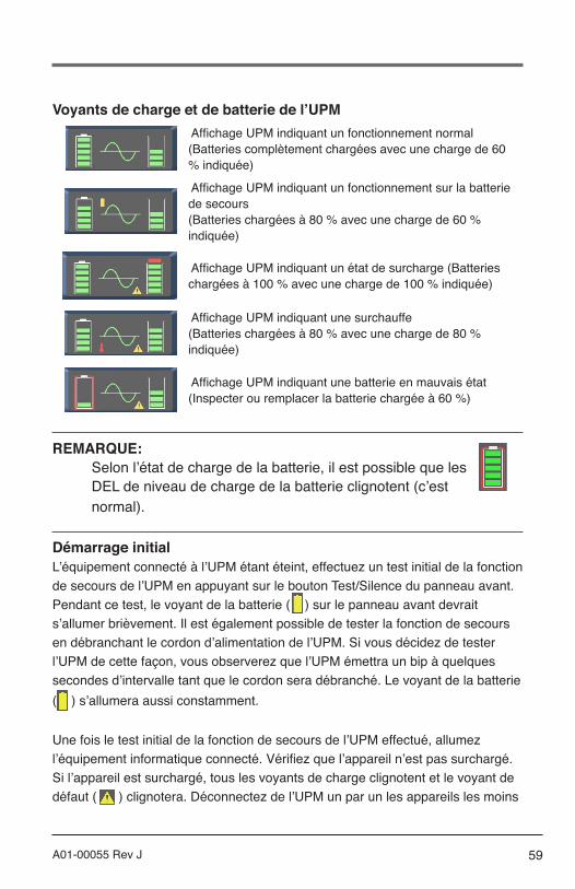
59A01-00055 Rev J
Voyants de charge et de batterie de l’UPM Affichage UPM indiquant un fonctionnement normal(Batteries complètement chargées avec une charge de 60% indiquée)
Affichage UPM indiquant un fonctionnement sur la batterie de secours(Batteries chargées à 80 % avec une charge de 60 % indiquée)
Affichage UPM indiquant un état de surcharge (Batteries chargées à 100 % avec une charge de 100 % indiquée)
Affichage UPM indiquant une surchauffe(Batteries chargées à 80 % avec une charge de 80 % indiquée)
Affichage UPM indiquant une batterie en mauvais état(Inspecter ou remplacer la batterie chargée à 60 %)
REMARQUE:Selon l’état de charge de la batterie, il est possible que les DEL de niveau de charge de la batterie clignotent (c’est normal).
Démarrage initialL’équipement connecté à l’UPM étant éteint, effectuez un test initial de la fonction de secours de l’UPM en appuyant sur le bouton Test/Silence du panneau avant. Pendant ce test, le voyant de la batterie ( ) sur le panneau avant devrait s’allumer brièvement. Il est également possible de tester la fonction de secours en débranchant le cordon d’alimentation de l’UPM. Si vous décidez de tester l’UPM de cette façon, vous observerez que l’UPM émettra un bip à quelques secondes d’intervalle tant que le cordon sera débranché. Le voyant de la batterie ( ) s’allumera aussi constamment.
Une fois le test initial de la fonction de secours de l’UPM effectué, allumez l’équipement informatique connecté. Vérifiez que l’appareil n’est pas surchargé. Si l’appareil est surchargé, tous les voyants de charge clignotent et le voyant de défaut ( ) clignotera. Déconnectez de l’UPM un par un les appareils les moins

60 A01-00055 Rev J
importants jusqu’à ce que les voyants de surcharge s’éteignent. En gardant les charges connectées allumées, effectuez le test de secours à nouveau en appuyant sur le bouton Test/ Silence ou en débranchant l’UPM. Une fois ce test final terminé, l’UPM est prêt à être utilisé.
Consulter le tableau des codes de défaut UPM ci-dessous pour identifier l’état de l’UPM.
Code d’état UPM DéfinitionIF Défaillance de l’inverseurBE Défaillance de réalimentationHL Appareil éteint en raison d’une tension élevéeLL Appareil éteint en raison d’une tension basseDB Appareil éteint en raison d’une batterie faibleFF Défaillance du ventilateurSF Défaut de câblage du site
REMARQUE:• Si l’UPM est allumé en permanence, il effectuera un test
automatique de la batterie tous les six jours.• Si vous utilisez le logiciel MopUPS Express, vous pouvez
configurer le système pour effectuer ce test automatiquement périodiquement.
• L’UPM est expédié avec une batterie chargée, mais il est normal qu’elle se décharge partiellement pendant l’entreposage et l’expédition. Vous pouvez utiliser l’UPM immédiatement, mais vous devez savoir que la durée d’autonomie disponible peut être inférieure à la valeur annoncée tant que la batterie de l’UPM n’aura pas été rechargée pendant au moins six heures.
• AMETEK-Powervar recommande de ne pas connecter d’imprimantes laser à l’UPM. Les imprimantes laser sont connues pour utiliser beaucoup de courant lorsque l’ensemble unité de fusion-chauffage est sous tension. Les imprimantes laser peuvent facilement surcharger l’UPM ou créer une baisse de tension qui peut interférer avec le fonctionnement du circuit de gestion de la tension.
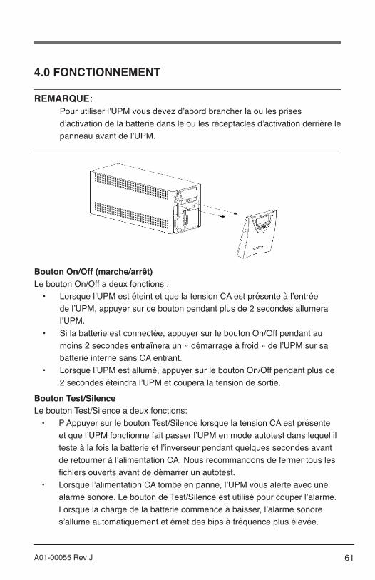
61A01-00055 Rev J
4.0 FONCTIONNEMENT
REMARQUE:Pour utiliser l’UPM vous devez d’abord brancher la ou les prises d’activation de la batterie dans le ou les réceptacles d’activation derrière le panneau avant de l’UPM.
Bouton On/Off (marche/arrêt)Le bouton On/Off a deux fonctions :
• Lorsque l’UPM est éteint et que la tension CA est présente à l’entrée de l’UPM, appuyer sur ce bouton pendant plus de 2 secondes allumera l’UPM.
• Si la batterie est connectée, appuyer sur le bouton On/Off pendant au moins 2 secondes entraînera un « démarrage à froid » de l’UPM sur sa batterie interne sans CA entrant.
• Lorsque l’UPM est allumé, appuyer sur le bouton On/Off pendant plus de 2 secondes éteindra l’UPM et coupera la tension de sortie.
Bouton Test/SilenceLe bouton Test/Silence a deux fonctions:
• P Appuyer sur le bouton Test/Silence lorsque la tension CA est présente et que l’UPM fonctionne fait passer l’UPM en mode autotest dans lequel il teste à la fois la batterie et l’inverseur pendant quelques secondes avant de retourner à l’alimentation CA. Nous recommandons de fermer tous les fichiers ouverts avant de démarrer un autotest.
• Lorsque l’alimentation CA tombe en panne, l’UPM vous alerte avec une alarme sonore. Le bouton de Test/Silence est utilisé pour couper l’alarme. Lorsque la charge de la batterie commence à baisser, l’alarme sonore s’allume automatiquement et émet des bips à fréquence plus élevée.
62 A01-00055 Rev J
Moniteur de chargeLe moniteur de charge est un affichage DEL à 6 segments qui indique la charge actuelle en pourcentage. Chacune des premières 5 DEL correspond à une charge d’environ 20 %, avec la 6ème DEL rouge indiquant que l’UPM est surchargé.
Moniteur de charge de la batterieLe moniteur de charge de la batterie est un affichage DEL à 5 segments qui indique la capacité de charge de la batterie interne de zéro à 100 %. Chaque DEL indique environ 20 % de la pleine charge.
Indicateur de défaut de câblage du site (modèles de 120 VCA uniquement)Le symbole SF s’affichera sur le panneau avant de l’UPM si celui-ci est connecté à une prise CA mal câblée. L’indicateur est prévu pour indiquer l’absence de fil de terre de sécurité ou une inversion entre le neutre etla phase. Si le « SF » s’affiche sur le panneau avant, adressez-vousimmédiatement à un électricien qualifié.
REMARQUE:Ne pas faire fonctionner l’UPM si la DEL de défaut de câblage du site est allumée. Lorsqu’elle est allumée, la DEL indique un câblage qui peut représenter un danger d’incendie ou d’électrocution. De plus, un mauvais câblage peut causer des problèmes de fiabilité à la fois pour l’UPM et pour le système qui y connecté. Ne jamais utiliser un adaptateur 3 pôles - 2 pôles (souvent appelé « tricheur ») avec l’UPM. Ces dispositifs suppriment la connexion de sécurité à la terre de l’UPM et feront s’allumer la DEL de défaut de câblage de site.
MopUPS ProLes communications intelligentes AMETEK-Powervar vous donnent plusieurs options pour :
• Protection des données sur un ordinateur alimenté par UPM lorsque la batterie est faible
• Surveillance de l’UPM pour permettre une analyse de l’historique d’alimentation du site et de l’état de l’UMP

63A01-00055 Rev J
Le port DB9 fournit une interface base-signal standard qui fonctionne avec le logiciel de surveillance héritage et UPS open source pour déclencher l’arrêt automatisé de l’ordinateur en conditions de batterie faible.
Le port USB intelligent relie votre UPM Series directement à Windows, Linux ou MAC OS comme un périphérique HID sans besoin de pilotes de périphériques USB supplémentaires. Utilisez les utilitaires de gestiond’énergie du SE natif pour l’arrêt automatique sécurisé en cas de batterie faible.
Si vous voulez des fonctionnalités supplémentaires, y compris :la consignation des données et des événements, des fichiersde commande d’exécution automatique avant l’arrêt, l’accès à la configuration UPM et à l’agent de réseau intégré pour la surveillance centralisée via le logiciel AMETEK-Powervar ManageUPS® CIO Server, le téléchargement et l’utilisation du logiciel AMETEK-Powervar MopUPS® Pro (pour Windows et Linux).
Port de gestion de la communicationLe gestionnaire de communication fournit un point de connexion sur le panneau arrière de l’UPM (ports DB9 et USB). En vous connectant à ce port et en installant le progiciel MopUPS Pro (en option), vous pourrez commander les fonctions importantes de l’UPM et accéder aux informations de fonctionnement de l’UPM. En utilisant le logiciel, vous pouvez visualiser des paramètres comme les tensions CA d’entrée et de sortie, la fréquence de la ligne d’alimentation et la tension de la batterie.
Pour prendre en charge ces fonctions sans la suite logicielle MopUPS Pro, vous devrez soit acheter ou construire votre propre câble spécial. Le tableau suivant décrit l’affectation des broches du connecteur DB9 à l’arrière de l’UPM. Contactez le fournisseur de votre ordinateur pour déterminer la configuration de la connexion et le type de connecteur nécessaire pour brancher le câble à l’ordinateur.
DB-9 Definition for UPMPin Description1 Batterie faible - niveau RS2322 RS232 RX3 RS232 TX
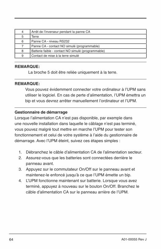
64 A01-00055 Rev J
4 Arrêt de l’inverseur pendant la panne CA5 Terre6 Panne CA - niveau RS2327 Panne CA - contact NO simulé (programmable)8 Batterie faible - contact NO simulé (programmable)9 Contact de mise à la terre simulé
REMARQUE: La broche 5 doit être reliée uniquement à la terre.
REMARQUE:Vous pouvez évidemment connecter votre ordinateur à l’UPM sans utiliser le logiciel. En cas de perte d’alimentation, l’UPM émettra un bip et vous devrez arrêter manuellement l’ordinateur et l’UPM.
Gestionnaire de démarrageLorsque l’alimentation CA n’est pas disponible, par exemple dans une nouvelle installation dans laquelle le câblage n’est pas terminé, vous pouvez malgré tout mettre en marche l’UPM pour tester son fonctionnement et celui de votre système à l’aide du gestionnaire de démarrage. Avec l’UPM éteint, suivez ces étapes simples :
1. Débranchez le câble d’alimentation CA de l’alimentation secteur.2. Assurez-vous que les batteries sont connectées derrière le
panneau avant.3. Appuyez sur le commutateur On/Off sur le panneau avant et
maintenez-le enfoncé jusqu’à ce que l’UPM émette un bip.4. L’UPM fonctionne maintenant sur batterie. Lorsque vous avez
terminé, appuyez à nouveau sur le bouton On/Off. Branchez le câble d’alimentation CA sur le panneau arrière de l’UPM.
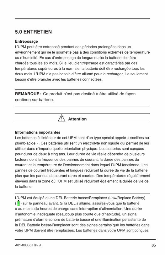
65A01-00055 Rev J
5.0 ENTRETIEN
Entreposage L’UPM peut être entreposé pendant des périodes prolongées dans un environnement qui ne le soumette pas à des conditions extrêmes de température ou d’humidité. En cas d’entreposage de longue durée la batterie doit être chargée tous les six mois. Si le lieu d’entreposage est caractérisé par des températures supérieures à la normale, la batterie doit être rechargée tous les deux mois. L’UPM n’a pas besoin d’être allumé pour le recharger, il a seulement besoin d’être branché avec les batteries connectées.
REMARQUE: Ce produit n’est pas destiné à être utilisé de façon continue sur batterie.
Attention
Informations importantesLes batteries à l’intérieur de cet UPM sont d’un type spécial appelé « scellées au plomb-acide ». Ces batteries utilisent un électrolyte non liquide qui permet de les utiliser dans n’importe quelle orientation physique. Les batteries sont conçues pour durer de deux à cinq ans. Leur durée de vie réelle dépendra de plusieurs facteurs dont la fréquence des pannes de courant, la durée des pannes de courant et la température de l’environnement dans lequel l’UPM fonctionne. Les pannes de courant fréquentes et longues réduiront la durée de vie de la batterie plus que les pannes de courant rares et courtes. Des températures régulièrement élevées dans la zone où l’UPM est utilisé réduiront également la durée de vie de la batterie.
L’UPM est équipé d’une DEL Batterie basse/Remplacer (Low/Replace Battery) ( ) sur le panneau avant. Si la DEL s’allume, assurez-vous que la batterie a au moins six heures de charge sans interruption d’alimentation. Une durée d’autonomie inadéquate (beaucoup plus courte que d’habitude), un signal prématuré d’alarme sonore de batterie basse et une illumination persistante de la DEL Batterie basse/Remplacer sont des signes certains que les batteries dans votre UPM doivent être remplacées. Les batteries dans votre UPM sont conçues

66 A01-00055 Rev J
pour être remplacées par un personnel autorisé seulement. Veuillez vous familiariser avec les précautions qui suivent avant de procéder au remplacement de la batterie.
AVERTISSEMENT
L’entretien des batteries doit toujours être fait ou supervisé par une personne ayant lu et compris les précautions qui suivent et qui comprend les dangers associés aux batteries d’accumulateurs. Cette procédure ne doit pas être exécutée par une personne qui n’y est pas autorisée ou qui est incapable de suivre ces consignes.
ATTENTION• Seul le bloc batterie est remplaçable par l’utilisateur dans cet appareil
(appareils non médicaux en bon état uniquement). Le compartiment des batteries est accessible en enlevant le panneau avant selon les instructions suivantes. Il n’existe aucun autre élément dans cet UPM qui puisse être remplacé par l’utilisateur. N’enlevez aucun capot autre que les panneaux avant d’accès aux batteries.
• Une batterie (même déchargée) peut envoyer des courants de forte intensité si elle est court-circuitée. Il existe un danger d’électrocution. Enlevez toutes les montres, bagues et tous les bracelets ou autres objets métalliques. Utilisez des outils à poignées isolées.
• Ne pas mettre les batteries au feu. Il existe un danger d’explosion.• Ne vous débarrassez pas des batteries d’une façon qui pourrait affecter
l’environnement. Les batteries peuvent être renvoyées à AMETEK-Powervar pour être éliminées correctement.
• Ne pas ouvrir ou endommager les batteries. Cela pourrait libérer l’électrolyte qui est toxique pour l’environnement et dangereux pour la peau et les yeux.
• Les batteries de rechange peuvent être commandées auprès de AMETEK-Powervar par téléphone ou par notre site web www.powervar.com. Si vous achetez des batteries d’une autre source, assurez-vous d’utiliser le type et la quantité de batteries requis.
• Les appareils médicaux n’ont aucune pièce réparable par l’utilisateur à l’intérieur.
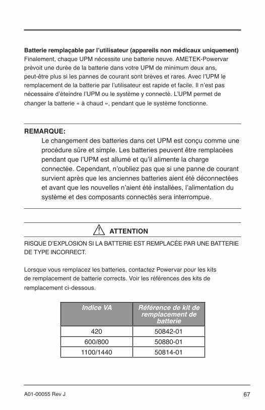
67A01-00055 Rev J
Batterie remplaçable par l’utilisateur (appareils non médicaux uniquement)Finalement, chaque UPM nécessite une batterie neuve. AMETEK-Powervar prévoit une durée de la batterie dans votre UPM de minimum deux ans, peut-être plus si les pannes de courant sont brèves et rares. Avec l’UPM le remplacement de la batterie par l’utilisateur est rapide et facile. Il n’est pas nécessaire d’éteindre l’UPM ou le système y connecté. L’UPM permet de changer la batterie « à chaud », pendant que le système fonctionne.
REMARQUE: Le changement des batteries dans cet UPM est conçu comme une procédure sûre et simple. Les batteries peuvent être remplacées pendant que l’UPM est allumé et qu’il alimente la charge connectée. Cependant, n’oubliez pas que si une panne de courant survient après que les anciennes batteries aient été déconnectées et avant que les nouvelles n’aient été installées, l’alimentation du système et des composants connectés sera interrompue.
ATTENTIONRISQUE D’EXPLOSION SI LA BATTERIE EST REMPLACÉE PAR UNE BATTERIE DE TYPE INCORRECT.
Lorsque vous remplacez les batteries, contactez Powervar pour les kits de remplacement de batterie corrects. Voir les références des kits de remplacement ci-dessous.
Indice VA Référence de kit de remplacement de
batterie420 50842-01
600/800 50880-011100/1440 50814-01

68 A01-00055 Rev J
ATTENTIONRisque de danger électrique, batterie de 12 V, maximum 8,5 ampères- heures. Avant de remplacer les batteries, retirez les bijoux conducteurs comme les chaînes, les bracelets-montres et les bagues. De forts courants à travers un matériau conducteur peuvent provoquer des brûlures graves.
ATTENTIONNe pas jeter les batteries au feu. Les batteries peuvent exploser.
ATTENTIONNe pas ouvrir ou endommager les batteries. La substance libérée est dangereuse pour la peau et les yeux. Elle peut être toxique. Une batterie peut présenter un risque de décharge électrique et de courant de court circuit de forte intensité. Les précautions suivantes doivent être priseslorsqu’on travaille avec des batteries :
• Retirez les montres, les bagues ou autres objets métalliques.• Utiliser des outils à poignées isolées.• Portez des gants et des bottes en caoutchouc.• Ne posez pas d’outils ou de pièces métalliques sur les batteries.• Déconnectez la source de charge avant de connecter ou
déconnecter les bornes de la batterie.• Vérifiez que la batterie n’est pas mise à la terre par inadvertance.• Si elle est mise à la terre, retirez la source de terre. Le contact
avec une batterie mise à la terre peut entraîner une électrocution.
REMARQUE: Si vous avez lu et compris les avertissements précédant cette section, vous pouvez procéder comme suit. Consultez la figure à la page 16 pour vous aider lors de la procédure de remplacement de la batterie suivante.

69A01-00055 Rev J
Remplacement de la batterie (appareils non médicaux uniquement)1. Tirez avec précaution sur le panneau avant pour le séparer de
l’appareil. Le panneau devrait sortir facilement.2. Séparez les connecteurs rouge et noir l’un de l’autre.3. Desserrez les (2) vis à ailettes qui attachent la porte de la batterie à
l’appareil.4. Retirez la porte de la batterie. Sortez la vieille batterie en la faisant
glisser avec précaution et mettez-la de côté.5. Remplacez-la par une nouvelle batterie (assurez-vous d’utiliser la
même taille et type de batterie).6. Réinstallez la porte de la batterie et serrez les vis à ailettes.7. Reconnectez les connecteurs rouge et noir.8. Remettez soigneusement le panneau avant sur l’UPM (faites
attention à ne pas pincer les câbles de la batterie).
Access additional product information and support on the web at
http://www.powervar.com
A01-00055 Rev J – 10/2015 - © 2015 POWERVAR, Inc.
USA Address:1450 Lakeside DriveWaukegan, IL 60085
1-800-369-7179(P) 847-596-7000(F) 847-596-7100
Canada Address:700 Finley Avenue, Unit 3Ajax, Ontario L1S 3Z2
(P) 905-239-9284
Europe/Asia Address:Unit 5, Birch-Kembrey ParkSwindon, Wilts SN2 8UU UK
(P) +44 1793 553980(F) +44 1793 535350
Mexico Address:Camino a la MontanaNo. 178-101 & PB4Fracc. Industrial La Perla,53340 Naucalpan, Edo De Mexico
(P) (52) 55 5363 5448