Embed Size (px)
Citation preview
Seediscussions,stats,andauthorprofilesforthispublicationat:https://www.researchgate.net/publication/235339185
Securityof3GandLTE
Data·January2012
CITATIONS
5
READS
1,511
2authors,including:
Someoftheauthorsofthispublicationarealsoworkingontheserelatedprojects:
CharacterizingtheStrengthofObfuscationViewproject
SebastianBanescu
BMW
32PUBLICATIONS122CITATIONS
SEEPROFILE
AllcontentfollowingthispagewasuploadedbySebastianBanescuon31May2014.
Theuserhasrequestedenhancementofthedownloadedfile.
Security of 3G and LTESebastian Banescu
Faculty of Computer ScienceEindhoven University of Technology
Simona PoseaFaculty of Computer Science
Eindhoven University of Technology
Abstract—3G is the third generation digital network developed by3GPP to provide telecommunication services to users. Althoughclaimed to be secure, scientific literature proves that 3G designremains vulnerable to malicious actions. As a response to thesecurity issues faced by 3G, a new security architecture wasdeveloped for Long Term Evolution (LTE).This paper presents the main security features of 3G and LTEdigital cellular networks and provides an in depth view of thenetwork access security and network domain security. A denialof service attack against the presence service supported in 3Gnetwork as well as two attacks against the cryptographic ciphersKASUMI and SNOW3G used in currently deployed systems arealso described in detail. Finally, general remarks and conclusionsregarding the security of 3G and LTE networks are given.
I. INTRODUCTION
The Global System for Mobile Communications (GSM) is astandard set developed by the European TelecommunicationsStandards Institute (ETSI) to describe technologies for secondgeneration (2G) digital cellular networks. Originally developedas a replacement for first generation analog cellular networks,the GSM standard described a digital circuit switched networkoptimized for full duplex voice telephony. The standard wasexpanded over time to include first circuit switched data trans-port, then packet data transport via GPRS. Even though thesecond generation of digital cellular networks were designedto protect the confidentiality of user traffic and to prevent cellphone cloning fraud [1], attackers have found other ways ofsubverting the safeguards of GSM [2], [3].
Subsequently the third generation (3G) digital cellular net-
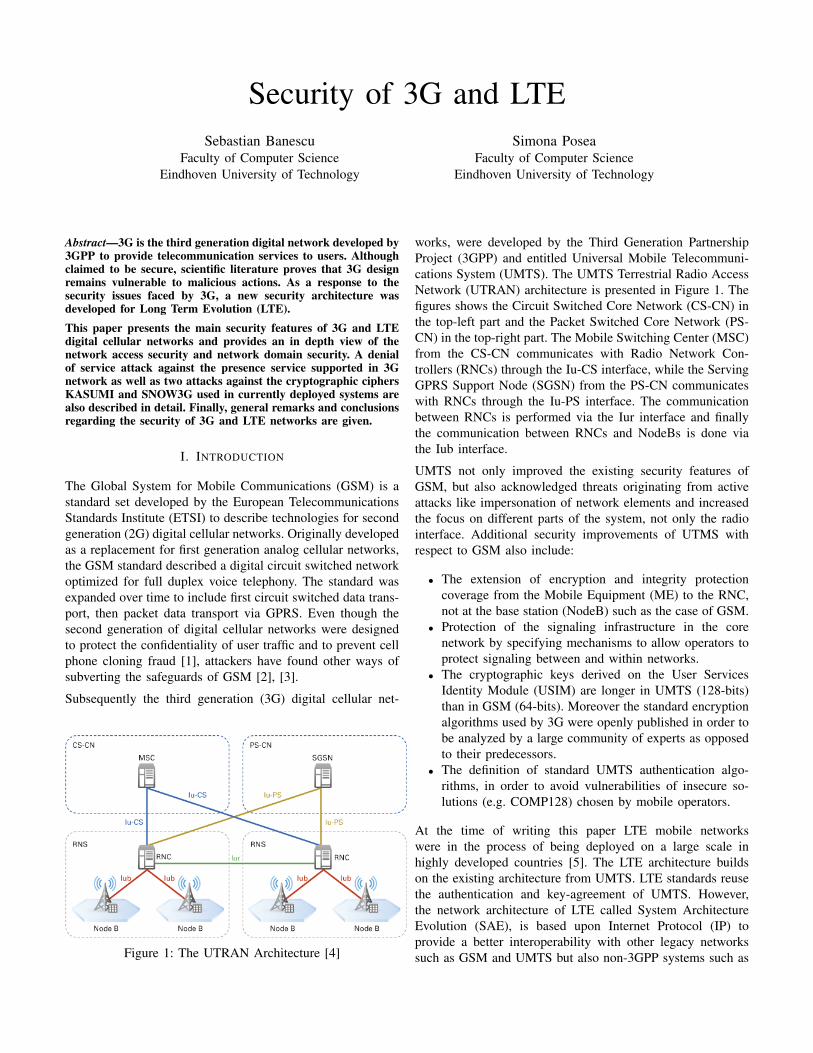
Figure 1: The UTRAN Architecture [4]
works, were developed by the Third Generation PartnershipProject (3GPP) and entitled Universal Mobile Telecommuni-cations System (UMTS). The UMTS Terrestrial Radio AccessNetwork (UTRAN) architecture is presented in Figure 1. Thefigures shows the Circuit Switched Core Network (CS-CN) inthe top-left part and the Packet Switched Core Network (PS-CN) in the top-right part. The Mobile Switching Center (MSC)from the CS-CN communicates with Radio Network Con-trollers (RNCs) through the Iu-CS interface, while the ServingGPRS Support Node (SGSN) from the PS-CN communicateswith RNCs through the Iu-PS interface. The communicationbetween RNCs is performed via the Iur interface and finallythe communication between RNCs and NodeBs is done viathe Iub interface.
UMTS not only improved the existing security features ofGSM, but also acknowledged threats originating from activeattacks like impersonation of network elements and increasedthe focus on different parts of the system, not only the radiointerface. Additional security improvements of UTMS withrespect to GSM also include:
• The extension of encryption and integrity protectioncoverage from the Mobile Equipment (ME) to the RNC,not at the base station (NodeB) such as the case of GSM.
• Protection of the signaling infrastructure in the corenetwork by specifying mechanisms to allow operators toprotect signaling between and within networks.
• The cryptographic keys derived on the User ServicesIdentity Module (USIM) are longer in UMTS (128-bits)than in GSM (64-bits). Moreover the standard encryptionalgorithms used by 3G were openly published in order tobe analyzed by a large community of experts as opposedto their predecessors.
• The definition of standard UMTS authentication algo-rithms, in order to avoid vulnerabilities of insecure so-lutions (e.g. COMP128) chosen by mobile operators.
At the time of writing this paper LTE mobile networkswere in the process of being deployed on a large scale inhighly developed countries [5]. The LTE architecture buildson the existing architecture from UMTS. LTE standards reusethe authentication and key-agreement of UMTS. However,the network architecture of LTE called System ArchitectureEvolution (SAE), is based upon Internet Protocol (IP) toprovide a better interoperability with other legacy networkssuch as GSM and UMTS but also non-3GPP systems such as
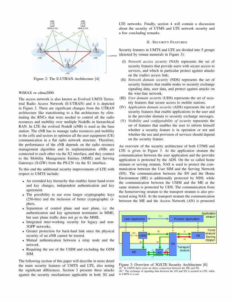
Figure 2: The E-UTRAN Architecture [4]
WiMAX or cdma2000.
The access network is also known as Evolved UMTS Terres-trial Radio Access Network (E-UTRAN) and it is depictedin Figure 2. There are significant changes from the UTRANarchitecture like transitioning to a flat architecture by elim-inating the RNCs that were needed to control all the radioresources and mobility over multiple NodeBs in hierarchicalRAN. In LTE the evolved NodeB (eNB) is used as the basestation. The eNB has to manage radio resources and mobilityin the cells and sectors to optimize all the user equipment (UE)communication in a flat radio network structure. Therefore,the performance of the eNB depends on the radio resourcemanagement algorithm and its implementation. eNBs areconnected to each other via the X2 interface, and they connectto the Mobility Management Entities (MME) and ServingGateways (S-GW) from the PS-CN via the S1 interface.
To this end the additional security improvements of LTE withrespect to UMTS include:
• An extended key hierarchy that enables faster hand-oversand key changes, independent authentication and keyagreement.
• The possibility to use even longer cryptographic keys(256-bits) and the inclusion of better cryptographic ci-phers.
• Separation of control plane and user plane, i.e. theauthentication and key agreement terminates in MME,but user plane traffic does not go to the MME.
• Integrated inter-working security for legacy and non-3GPP networks.
• Greater protection for back-haul link since the physicalsecurity of an eNB cannot be trusted.
• Mutual authentication between a relay node and thenetwork.
• Requiring the use of the USIM and excluding the GSMSIM.
The following section of this paper will describe in more detailthe main security features of UMTS and LTE, also notingthe significant differences. Section 3 presents three attacksagainst the security mechanisms applicable in both 3G and
LTE networks. Finally, section 4 will contain a discussionabout the security of UTMS and LTE network security anda few concluding remarks.
II. SECURITY FEATURES
Security features in UMTS and LTE are divided into 5 groups(denoted by roman numerals in Figure 3):
(I) Network access security (NAS) represents the set ofsecurity features that provide users with secure access toservices, and which in particular protect against attackson the (radio) access link;
(II) Network domain security (NDS) represents the set ofsecurity features that enable nodes to securely exchangesignaling data, user data, and protect against attacks onthe wire-line network.
(III) User domain security (UDS) represents the set of secu-rity features that secure access to mobile stations.
(IV) Application domain security (ADS) represents the set ofsecurity features that enable applications in the user andin the provider domain to securely exchange messages.
(V) Visibility and configurability of security represents theset of features that enables the user to inform himselfwhether a security feature is in operation or not andwhether the use and provision of services should dependon the security feature.
An overview of the security architecture of both UTMS andLTE is given in Figure 3. At the application stratum thecommunication between the user application and the providerapplication is protected by the ADS. On the so called homestratum or serving stratum, NAS is used to protect the com-munication between the User SIM and the Serving Network(SN). The communication between the SN and the HomeEnvironment (HE) is additionally protected by NDS, whilethe communication between the USIM and the ME at thesame stratum is protected by UDS. The communication fromthe home/serving stratum to the transport stratum is also pro-tected using NAS. At the transport stratum the communicationbetween the ME and the Access Network (AN) is protected
Figure 3: Overview of 3G/LTE Security Architecture [6](I)∗ In UMTS there exists no direct connection between the ME and SN.(II)∗ The exchange of signaling data between the AN and SN is secured in LTE, whilein UMTS it is not.
ME VLR/SGSN HE/HLRAuthentication data request
Generateauthenticationvectors AV(1..n)
Authentication data response AV(1..n)
Store Authentication Vectors
Select authentication vector AV(i)
User authentication requestRAND(i) || AUTN(i)
Verify AUTN(i)Compute RES(i)
User authentication responseRES(i)
Compare RES(i) and XRES(i)
ComputeCK(i) and IK(i)
SelectCK(i) and IK(i)
Authenticationand keyestablishment
Distribution ofauthenticationvectors fromHE to SN
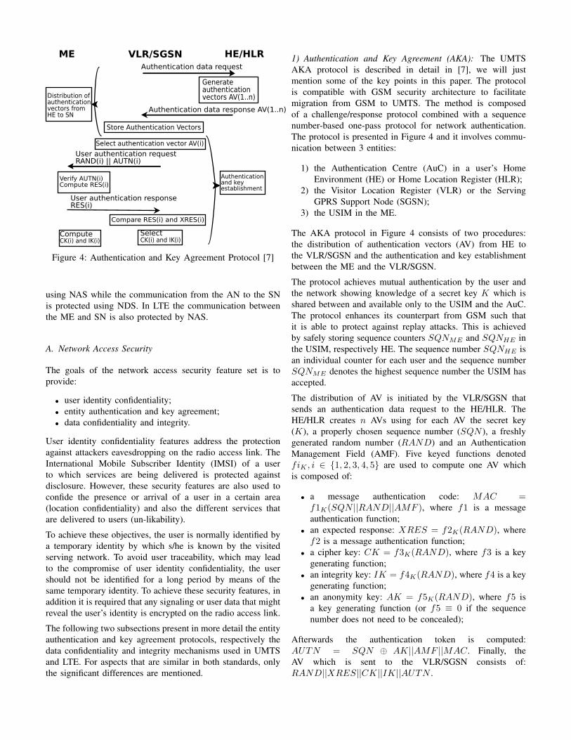
Figure 4: Authentication and Key Agreement Protocol [7]
using NAS while the communication from the AN to the SNis protected using NDS. In LTE the communication betweenthe ME and SN is also protected by NAS.
A. Network Access Security
The goals of the network access security feature set is toprovide:
• user identity confidentiality;• entity authentication and key agreement;• data confidentiality and integrity.
User identity confidentiality features address the protectionagainst attackers eavesdropping on the radio access link. TheInternational Mobile Subscriber Identity (IMSI) of a userto which services are being delivered is protected againstdisclosure. However, these security features are also used toconfide the presence or arrival of a user in a certain area(location confidentiality) and also the different services thatare delivered to users (un-likability).
To achieve these objectives, the user is normally identified bya temporary identity by which s/he is known by the visitedserving network. To avoid user traceability, which may leadto the compromise of user identity confidentiality, the usershould not be identified for a long period by means of thesame temporary identity. To achieve these security features, inaddition it is required that any signaling or user data that mightreveal the user’s identity is encrypted on the radio access link.
The following two subsections present in more detail the entityauthentication and key agreement protocols, respectively thedata confidentiality and integrity mechanisms used in UMTSand LTE. For aspects that are similar in both standards, onlythe significant differences are mentioned.
1) Authentication and Key Agreement (AKA): The UMTSAKA protocol is described in detail in [7], we will justmention some of the key points in this paper. The protocolis compatible with GSM security architecture to facilitatemigration from GSM to UMTS. The method is composedof a challenge/response protocol combined with a sequencenumber-based one-pass protocol for network authentication.The protocol is presented in Figure 4 and it involves commu-nication between 3 entities:
1) the Authentication Centre (AuC) in a user’s HomeEnvironment (HE) or Home Location Register (HLR);
2) the Visitor Location Register (VLR) or the ServingGPRS Support Node (SGSN);
3) the USIM in the ME.
The AKA protocol in Figure 4 consists of two procedures:the distribution of authentication vectors (AV) from HE tothe VLR/SGSN and the authentication and key establishmentbetween the ME and the VLR/SGSN.
The protocol achieves mutual authentication by the user andthe network showing knowledge of a secret key K which isshared between and available only to the USIM and the AuC.The protocol enhances its counterpart from GSM such thatit is able to protect against replay attacks. This is achievedby safely storing sequence counters SQNME and SQNHE inthe USIM, respectively HE. The sequence number SQNHE isan individual counter for each user and the sequence numberSQNME denotes the highest sequence number the USIM hasaccepted.
The distribution of AV is initiated by the VLR/SGSN thatsends an authentication data request to the HE/HLR. TheHE/HLR creates n AVs using for each AV the secret key(K), a properly chosen sequence number (SQN ), a freshlygenerated random number (RAND) and an AuthenticationManagement Field (AMF). Five keyed functions denotedfiK , i ∈ {1, 2, 3, 4, 5} are used to compute one AV whichis composed of:
• a message authentication code: MAC =f1K(SQN ||RAND||AMF ), where f1 is a messageauthentication function;
• an expected response: XRES = f2K(RAND), wheref2 is a message authentication function;
• a cipher key: CK = f3K(RAND), where f3 is a keygenerating function;
• an integrity key: IK = f4K(RAND), where f4 is a keygenerating function;
• an anonymity key: AK = f5K(RAND), where f5 isa key generating function (or f5 ≡ 0 if the sequencenumber does not need to be concealed);
Afterwards the authentication token is computed:AUTN = SQN ⊕ AK||AMF ||MAC. Finally, theAV which is sent to the VLR/SGSN consists of:RAND||XRES||CK||IK||AUTN .
The user authentication and key establishment procedure fromthe lower part of Figure 4 is performed each time a ME wishesto request services from the VLR/SGSN. This is done in orderto establish a new pair of cipher and integrity keys betweenthe the ME and VLR/SGSN. The VLR/SGSN first sends auser authentication request to the ME containing the followingunused AV from the set of n AVs it previously received fromthe HE/HLR. Supposing that the ith AV is the following un-used AV, VLR/SGSN sends the pair RAND(i)||AUTN(i) tothe ME. The USIM retrieves the sequence number (SQN ) bycomputing the AK in the same way as the HE/HLR and thenXOR-ing it with the first part of the AUTN . Next, the USIMcomputes the expected MAC using the f1 function as HE/HLRand compares it to the received MAC. If they are different itrejects the user authentication, otherwise it verifies that SQNis in the correct range. In case SQN is not in the correct rangeit sends a synchronization failure to the VLR/SGSN, otherwiseit computes the response RES = f2K(RAND) and send itto the VLR/SGSN. Finally, the VLR/SGSN checks whetherthe response received from the ME matches the expectedresponse XRES(i). If they match then the cipher and integritykeys between the two parties have been established since theVLR/SGSN only needs to select CK(i) and IK(i) and theUSIM computes CK and IK using its secret key and therandom number received from the VLR/SGSN.
In the remainder of this subsection we present differencesand improvements of the LTE AKA protocol also knownas the Evolved Packet System (EPS) AKA protocol. Theauthentication part of the EPS-AKA protocol consists mainlyof the UMTS AKA protocol with some minor additions. Onechange is the fact that the EPS-AKA protocol is executedbetween UE and the MME instead of between the USIMand the VLR/SGSN. Secondly, one has amended the protocolto include indication that the protocol is run in an EPS/LTEcontext and not in a 3G context. With respect to the USIMthe protocol execution is exactly identical to the execution ofthe UMTS AKA protocol.
Another interesting change to the authentication is that theEPS Authentication Vector (EPS-AV) is generated for thespecific target network through inclusion of the SN Identityin the AV derivation, in order to authenticate the SN whenthe keys derived from the master key (KASME) are used.The UE (USIM/ME) will use the beaconed SN Identity whencomputing the AV. Technically speaking, the SN Identity ispart of the input when computing the KASME , using theconcatenated UMTS AKA keys (CK||IK) as the controllingkey as specified in [6] therefore the EPS-AV has the follow-ing form: EPS-AV = {KASME , RAND,AUTN,XRES}.The so-called separation bit in the AUTN part of the EPS-AKA challenge is set to indicate that the executed AKA isEPS-AKA and not UMTS AKA. This is verified by the ME(the USIM is oblivious to the difference between EPS-AKAand UMTS AKA; although it does verify that AUTN is validit has no knowledge of EPS/LTE as such). The MME sendsan authentication request to the UE of the following form
K
NASencK NASintK
UPintK UPencK RRCencKRRCintK
ASMEK
eNBK
UE / HSS
USIM / AuC
UE / MME
UE / eNB
CK, IK Derived using UMTS AKA
Permanent secretfor subscription
/NH
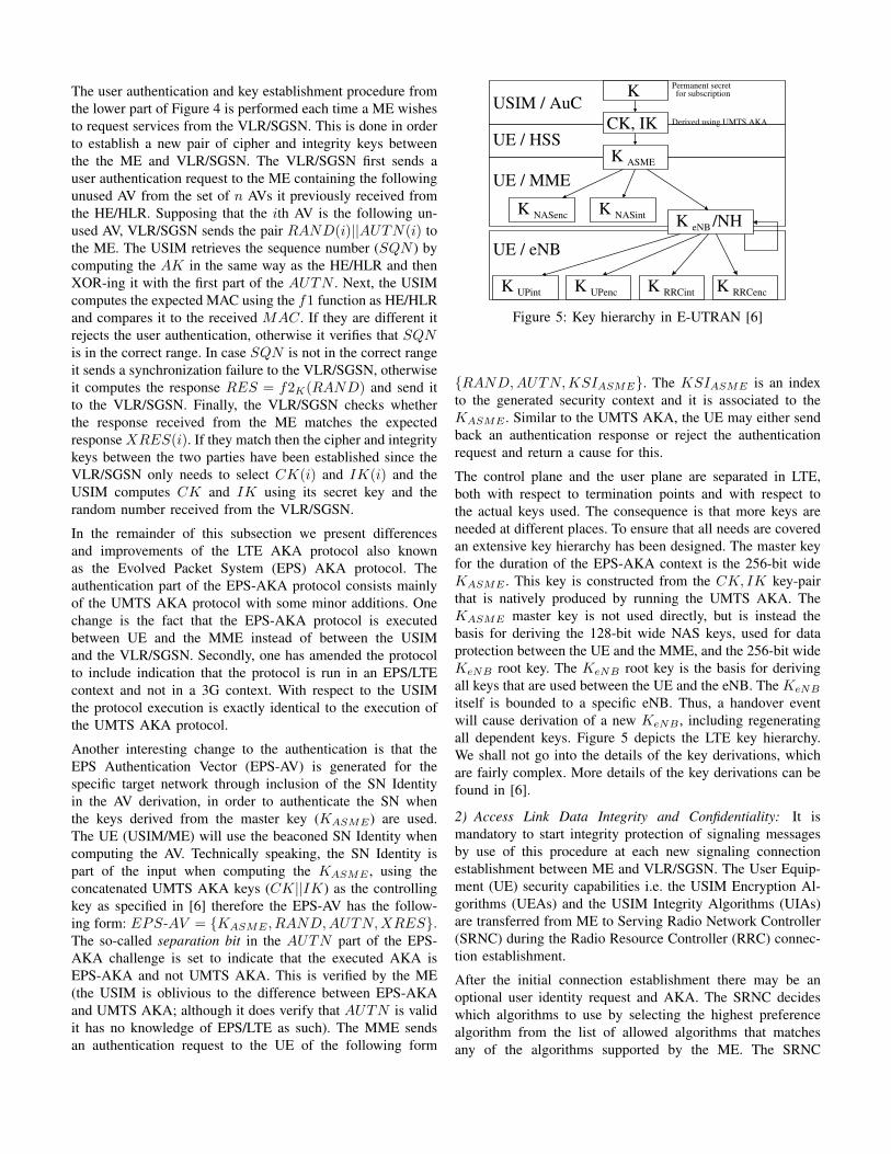
Figure 5: Key hierarchy in E-UTRAN [6]
{RAND,AUTN,KSIASME}. The KSIASME is an indexto the generated security context and it is associated to theKASME . Similar to the UMTS AKA, the UE may either sendback an authentication response or reject the authenticationrequest and return a cause for this.
The control plane and the user plane are separated in LTE,both with respect to termination points and with respect tothe actual keys used. The consequence is that more keys areneeded at different places. To ensure that all needs are coveredan extensive key hierarchy has been designed. The master keyfor the duration of the EPS-AKA context is the 256-bit wideKASME . This key is constructed from the CK, IK key-pairthat is natively produced by running the UMTS AKA. TheKASME master key is not used directly, but is instead thebasis for deriving the 128-bit wide NAS keys, used for dataprotection between the UE and the MME, and the 256-bit wideKeNB root key. The KeNB root key is the basis for derivingall keys that are used between the UE and the eNB. The KeNB
itself is bounded to a specific eNB. Thus, a handover eventwill cause derivation of a new KeNB , including regeneratingall dependent keys. Figure 5 depicts the LTE key hierarchy.We shall not go into the details of the key derivations, whichare fairly complex. More details of the key derivations can befound in [6].
2) Access Link Data Integrity and Confidentiality: It ismandatory to start integrity protection of signaling messagesby use of this procedure at each new signaling connectionestablishment between ME and VLR/SGSN. The User Equip-ment (UE) security capabilities i.e. the USIM Encryption Al-gorithms (UEAs) and the USIM Integrity Algorithms (UIAs)are transferred from ME to Serving Radio Network Controller(SRNC) during the Radio Resource Controller (RRC) connec-tion establishment.
After the initial connection establishment there may be anoptional user identity request and AKA. The SRNC decideswhich algorithms to use by selecting the highest preferencealgorithm from the list of allowed algorithms that matchesany of the algorithms supported by the ME. The SRNC
MESSAGE
COUNT−I DIRECTION
BEARER
FRESH/
f9/EIA
MAC−I
IK/
KEY
(a) Derivation of MAC
COUNT−C DIRECTION
BEARER
KEYSTREAM
BLOCK
PLAINTEXT CIPHERTEXT
BLOCK
LENGTH
BLOCK
CK/
KEY
f8/EEA
(b) Derivation of ciphertext
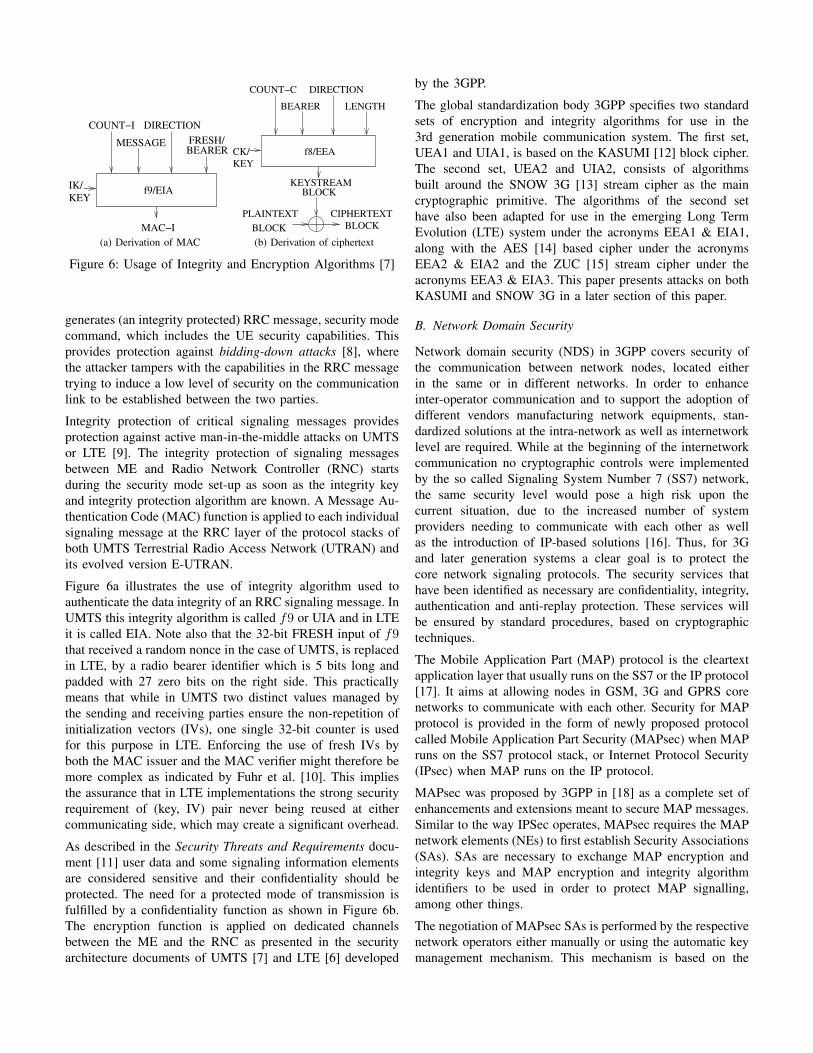
Figure 6: Usage of Integrity and Encryption Algorithms [7]
generates (an integrity protected) RRC message, security modecommand, which includes the UE security capabilities. Thisprovides protection against bidding-down attacks [8], wherethe attacker tampers with the capabilities in the RRC messagetrying to induce a low level of security on the communicationlink to be established between the two parties.
Integrity protection of critical signaling messages providesprotection against active man-in-the-middle attacks on UMTSor LTE [9]. The integrity protection of signaling messagesbetween ME and Radio Network Controller (RNC) startsduring the security mode set-up as soon as the integrity keyand integrity protection algorithm are known. A Message Au-thentication Code (MAC) function is applied to each individualsignaling message at the RRC layer of the protocol stacks ofboth UMTS Terrestrial Radio Access Network (UTRAN) andits evolved version E-UTRAN.
Figure 6a illustrates the use of integrity algorithm used toauthenticate the data integrity of an RRC signaling message. InUMTS this integrity algorithm is called f9 or UIA and in LTEit is called EIA. Note also that the 32-bit FRESH input of f9that received a random nonce in the case of UMTS, is replacedin LTE, by a radio bearer identifier which is 5 bits long andpadded with 27 zero bits on the right side. This practicallymeans that while in UMTS two distinct values managed bythe sending and receiving parties ensure the non-repetition ofinitialization vectors (IVs), one single 32-bit counter is usedfor this purpose in LTE. Enforcing the use of fresh IVs byboth the MAC issuer and the MAC verifier might therefore bemore complex as indicated by Fuhr et al. [10]. This impliesthe assurance that in LTE implementations the strong securityrequirement of (key, IV) pair never being reused at eithercommunicating side, which may create a significant overhead.
As described in the Security Threats and Requirements docu-ment [11] user data and some signaling information elementsare considered sensitive and their confidentiality should beprotected. The need for a protected mode of transmission isfulfilled by a confidentiality function as shown in Figure 6b.The encryption function is applied on dedicated channelsbetween the ME and the RNC as presented in the securityarchitecture documents of UMTS [7] and LTE [6] developed
by the 3GPP.
The global standardization body 3GPP specifies two standardsets of encryption and integrity algorithms for use in the3rd generation mobile communication system. The first set,UEA1 and UIA1, is based on the KASUMI [12] block cipher.The second set, UEA2 and UIA2, consists of algorithmsbuilt around the SNOW 3G [13] stream cipher as the maincryptographic primitive. The algorithms of the second sethave also been adapted for use in the emerging Long TermEvolution (LTE) system under the acronyms EEA1 & EIA1,along with the AES [14] based cipher under the acronymsEEA2 & EIA2 and the ZUC [15] stream cipher under theacronyms EEA3 & EIA3. This paper presents attacks on bothKASUMI and SNOW 3G in a later section of this paper.
B. Network Domain Security
Network domain security (NDS) in 3GPP covers security ofthe communication between network nodes, located eitherin the same or in different networks. In order to enhanceinter-operator communication and to support the adoption ofdifferent vendors manufacturing network equipments, stan-dardized solutions at the intra-network as well as internetworklevel are required. While at the beginning of the internetworkcommunication no cryptographic controls were implementedby the so called Signaling System Number 7 (SS7) network,the same security level would pose a high risk upon thecurrent situation, due to the increased number of systemproviders needing to communicate with each other as wellas the introduction of IP-based solutions [16]. Thus, for 3Gand later generation systems a clear goal is to protect thecore network signaling protocols. The security services thathave been identified as necessary are confidentiality, integrity,authentication and anti-replay protection. These services willbe ensured by standard procedures, based on cryptographictechniques.
The Mobile Application Part (MAP) protocol is the cleartextapplication layer that usually runs on the SS7 or the IP protocol[17]. It aims at allowing nodes in GSM, 3G and GPRS corenetworks to communicate with each other. Security for MAPprotocol is provided in the form of newly proposed protocolcalled Mobile Application Part Security (MAPsec) when MAPruns on the SS7 protocol stack, or Internet Protocol Security(IPsec) when MAP runs on the IP protocol.
MAPsec was proposed by 3GPP in [18] as a complete set ofenhancements and extensions meant to secure MAP messages.Similar to the way IPSec operates, MAPsec requires the MAPnetwork elements (NEs) to first establish Security Associations(SAs). SAs are necessary to exchange MAP encryption andintegrity keys and MAP encryption and integrity algorithmidentifiers to be used in order to protect MAP signalling,among other things.
The negotiation of MAPsec SAs is performed by the respectivenetwork operators either manually or using the automatic keymanagement mechanism. This mechanism is based on the
SADBSADB SPDBSPDB
SADBSADB SPDBSPDB
SADBSADB SPDBSPDB
SADBSADB SPDBSPDB
IKEconnection
PLMNB
MAPsecsecurityassociation
SAdistribution
PLMNA
MAPmessageexchange
NEA-1
NEA-2
NEB-1
NEB-2
KACBKACA
Ze
Ze Ze
Ze
Zd
Zf
Zf Zf
Figure 7: NDS Architecture when MAPsec is used to protectMAP messages
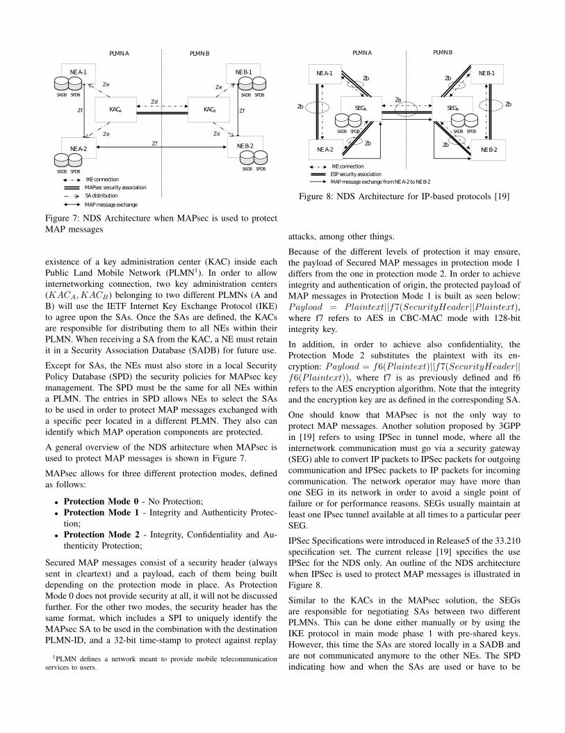
existence of a key administration center (KAC) inside eachPublic Land Mobile Network (PLMN1). In order to allowinternetworking connection, two key administration centers(KACA,KACB) belonging to two different PLMNs (A andB) will use the IETF Internet Key Exchange Protocol (IKE)to agree upon the SAs. Once the SAs are defined, the KACsare responsible for distributing them to all NEs within theirPLMN. When receiving a SA from the KAC, a NE must retainit in a Security Association Database (SADB) for future use.
Except for SAs, the NEs must also store in a local SecurityPolicy Database (SPD) the security policies for MAPsec keymanagement. The SPD must be the same for all NEs withina PLMN. The entries in SPD allows NEs to select the SAsto be used in order to protect MAP messages exchanged witha specific peer located in a different PLMN. They also canidentify which MAP operation components are protected.
A general overview of the NDS arhitecture when MAPsec isused to protect MAP messages is shown in Figure 7.
MAPsec allows for three different protection modes, definedas follows:
• Protection Mode 0 - No Protection;• Protection Mode 1 - Integrity and Authenticity Protec-
tion;• Protection Mode 2 - Integrity, Confidentiality and Au-
thenticity Protection;
Secured MAP messages consist of a security header (alwayssent in cleartext) and a payload, each of them being builtdepending on the protection mode in place. As ProtectionMode 0 does not provide security at all, it will not be discussedfurther. For the other two modes, the security header has thesame format, which includes a SPI to uniquely identify theMAPsec SA to be used in the combination with the destinationPLMN-ID, and a 32-bit time-stamp to protect against replay
1PLMN defines a network meant to provide mobile telecommunicationservices to users.
SADBSADB SPDBSPDB SADBSADB SPDBSPDB
IKEconnection
PLMNB
ESPsecurityassociation
PLMNA
MAPmessageexchangefromNEA-2toNEB-2
ZaZb
Zb Zb
Zb
ZbZb
NEA-1
NEA-2
NEB-1
NEB-2
SEGBSEGA
Figure 8: NDS Architecture for IP-based protocols [19]
attacks, among other things.
Because of the different levels of protection it may ensure,the payload of Secured MAP messages in protection mode 1differs from the one in protection mode 2. In order to achieveintegrity and authentication of origin, the protected payload ofMAP messages in Protection Mode 1 is built as seen below:Payload = Plaintext||f7(SecurityHeader||Plaintext),where f7 refers to AES in CBC-MAC mode with 128-bitintegrity key.
In addition, in order to achieve also confidentiality, theProtection Mode 2 substitutes the plaintext with its en-cryption: Payload = f6(Plaintext)||f7(SecurityHeader||f6(Plaintext)), where f7 is as previously defined and f6refers to the AES encryption algorithm. Note that the integrityand the encryption key are as defined in the corresponding SA.
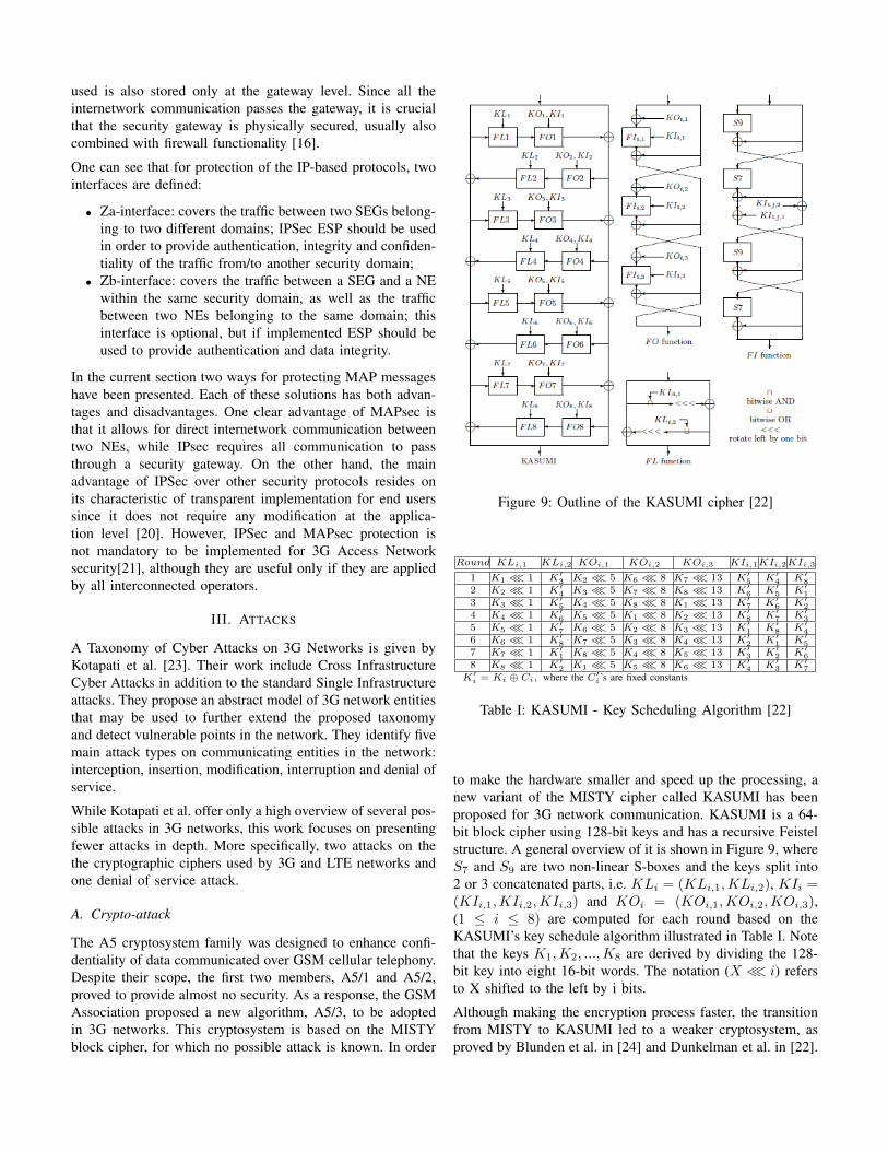
One should know that MAPsec is not the only way toprotect MAP messages. Another solution proposed by 3GPPin [19] refers to using IPSec in tunnel mode, where all theinternetwork communication must go via a security gateway(SEG) able to convert IP packets to IPSec packets for outgoingcommunication and IPSec packets to IP packets for incomingcommunication. The network operator may have more thanone SEG in its network in order to avoid a single point offailure or for performance reasons. SEGs usually maintain atleast one IPsec tunnel available at all times to a particular peerSEG.
IPSec Specifications were introduced in Release5 of the 33.210specification set. The current release [19] specifies the useIPSec for the NDS only. An outline of the NDS architecturewhen IPSec is used to protect MAP messages is illustrated inFigure 8.
Similar to the KACs in the MAPsec solution, the SEGsare responsible for negotiating SAs between two differentPLMNs. This can be done either manually or by using theIKE protocol in main mode phase 1 with pre-shared keys.However, this time the SAs are stored locally in a SADB andare not communicated anymore to the other NEs. The SPDindicating how and when the SAs are used or have to be
used is also stored only at the gateway level. Since all theinternetwork communication passes the gateway, it is crucialthat the security gateway is physically secured, usually alsocombined with firewall functionality [16].
One can see that for protection of the IP-based protocols, twointerfaces are defined:
• Za-interface: covers the traffic between two SEGs belong-ing to two different domains; IPSec ESP should be usedin order to provide authentication, integrity and confiden-tiality of the traffic from/to another security domain;
• Zb-interface: covers the traffic between a SEG and a NEwithin the same security domain, as well as the trafficbetween two NEs belonging to the same domain; thisinterface is optional, but if implemented ESP should beused to provide authentication and data integrity.
In the current section two ways for protecting MAP messageshave been presented. Each of these solutions has both advan-tages and disadvantages. One clear advantage of MAPsec isthat it allows for direct internetwork communication betweentwo NEs, while IPsec requires all communication to passthrough a security gateway. On the other hand, the mainadvantage of IPSec over other security protocols resides onits characteristic of transparent implementation for end userssince it does not require any modification at the applica-tion level [20]. However, IPSec and MAPsec protection isnot mandatory to be implemented for 3G Access Networksecurity[21], although they are useful only if they are appliedby all interconnected operators.
III. ATTACKS
A Taxonomy of Cyber Attacks on 3G Networks is given byKotapati et al. [23]. Their work include Cross InfrastructureCyber Attacks in addition to the standard Single Infrastructureattacks. They propose an abstract model of 3G network entitiesthat may be used to further extend the proposed taxonomyand detect vulnerable points in the network. They identify fivemain attack types on communicating entities in the network:interception, insertion, modification, interruption and denial ofservice.
While Kotapati et al. offer only a high overview of several pos-sible attacks in 3G networks, this work focuses on presentingfewer attacks in depth. More specifically, two attacks on thethe cryptographic ciphers used by 3G and LTE networks andone denial of service attack.
A. Crypto-attack
The A5 cryptosystem family was designed to enhance confi-dentiality of data communicated over GSM cellular telephony.Despite their scope, the first two members, A5/1 and A5/2,proved to provide almost no security. As a response, the GSMAssociation proposed a new algorithm, A5/3, to be adoptedin 3G networks. This cryptosystem is based on the MISTYblock cipher, for which no possible attack is known. In order
Figure 9: Outline of the KASUMI cipher [22]
Round KLi,1 KLi,2 KOi,1 KOi,2 KOi,3 KIi,1KIi,2KIi,3
1 K1 ≪ 1 K′3 K2 ≪ 5 K6 ≪ 8 K7 ≪ 13 K′5 K′4 K′82 K2 ≪ 1 K′4 K3 ≪ 5 K7 ≪ 8 K8 ≪ 13 K′6 K′5 K′13 K3 ≪ 1 K′5 K4 ≪ 5 K8 ≪ 8 K1 ≪ 13 K′7 K′6 K′24 K4 ≪ 1 K′6 K5 ≪ 5 K1 ≪ 8 K2 ≪ 13 K′8 K′7 K′35 K5 ≪ 1 K′7 K6 ≪ 5 K2 ≪ 8 K3 ≪ 13 K′1 K′8 K′46 K6 ≪ 1 K′8 K7 ≪ 5 K3 ≪ 8 K4 ≪ 13 K′2 K′1 K′57 K7 ≪ 1 K′1 K8 ≪ 5 K4 ≪ 8 K5 ≪ 13 K′3 K′2 K′68 K8 ≪ 1 K′2 K1 ≪ 5 K5 ≪ 8 K6 ≪ 13 K′4 K′3 K′7
K′i = Ki ⊕ Ci, where the C′i’s are fixed constants
Table I: KASUMI - Key Scheduling Algorithm [22]
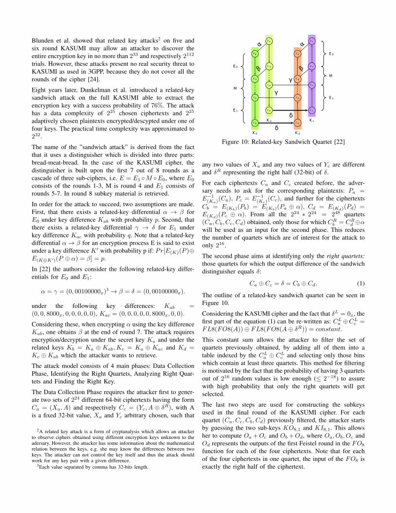
to make the hardware smaller and speed up the processing, anew variant of the MISTY cipher called KASUMI has beenproposed for 3G network communication. KASUMI is a 64-bit block cipher using 128-bit keys and has a recursive Feistelstructure. A general overview of it is shown in Figure 9, whereS7 and S9 are two non-linear S-boxes and the keys split into2 or 3 concatenated parts, i.e. KLi = (KLi,1,KLi,2), KIi =(KIi,1,KIi,2,KIi,3) and KOi = (KOi,1,KOi,2,KOi,3),(1 ≤ i ≤ 8) are computed for each round based on theKASUMI’s key schedule algorithm illustrated in Table I. Notethat the keys K1,K2, ...,K8 are derived by dividing the 128-bit key into eight 16-bit words. The notation (X≪ i) refersto X shifted to the left by i bits.
Although making the encryption process faster, the transitionfrom MISTY to KASUMI led to a weaker cryptosystem, asproved by Blunden et al. in [24] and Dunkelman et al. in [22].
Blunden et al. showed that related key attacks2 on five andsix round KASUMI may allow an attacker to discover theentire encryption key in no more than 233 and respectively 2112
trials. However, these attacks present no real security threat toKASUMI as used in 3GPP, because they do not cover all therounds of the cipher [24].
Eight years later, Dunkelman et al. introduced a related-keysandwich attack on the full KASUMI able to extract theencryption key with a success probability of 76%. The attackhas a data complexity of 225 chosen ciphertexts and 225
adaptively chosen plaintexts encrypted/descypted under one offour keys. The practical time complexity was approximated to232.
The name of the ”sandwich attack” is derived from the factthat it uses a distinguisher which is divided into three parts:bread-meat-bread. In the case of the KASUMI cipher, thedistinguisher is built upon the first 7 out of 8 rounds as acascade of three sub-ciphers, i.e. E = E1 ◦M ◦E0, where E0
consists of the rounds 1-3, M is round 4 and E1 consists ofrounds 5-7. In round 8 subkey material is retrieved.
In order for the attack to succeed, two assumptions are made.First, that there exists a related-key differential α → β forE0 under key difference Kab with probability p. Second, thatthere exists a related-key differential γ → δ for E1 underkey difference Kac with probability q. Note that a related-keydifferential α→ β for an encryption process E is said to existunder a key difference K ′ with probability p if: Pr[E(K)(P )⊕E(K⊕K′)(P ⊕ α) = β] = p.
In [22] the authors consider the following related-key differ-entials for E0 and E1:
α = γ = (0, 00100000x)3 → β = δ = (0, 00100000x).
under the following key differences: Kab =(0, 0, 8000x, 0, 0, 0, 0, 0), Kac = (0, 0, 0, 0, 0, 8000x, 0, 0).
Considering these, when encrypting α using the key differenceKab, one obtains β at the end of round 7. The attack requiresencryption/decryption under the secret key Ka and under therelated keys Kb = Ka ⊕ Kab,Kc = Ka ⊕ Kac and Kd =Kc ⊕Kab which the attacker wants to retrieve.
The attack model consists of 4 main phases: Data CollectionPhase, Identifying the Right Quartets, Analyzing Right Quar-tets and Finding the Right Key.
The Data Collection Phase requires the attacker first to gener-ate two sets of 224 different 64-bit ciphertexts having the formCa = (Xa, A) and respectively Cc = (Yc, A ⊕ δR), with Ais a fixed 32-bit value, Xa and Yc arbitrary chosen, such that
2A related key attack is a form of cryptanalysis which allows an attackerto observe ciphers obtained using different encryption keys unknown to theadersary. However, the attacker has some information about the mathematicalrelation between the keys, e.g. she may know the differences between twokeys. The attacker can not control the key itself and thus the attack shouldwork for any key pair with a given difference.
3Each value separated by comma has 32-bits length.
P a
P b
X a
X b
Y a
Y b
C a
C b
P c
P d
X c
X d
Y c
Y d
C c
C d
α
β
α
β
γ
γ
δ
δ
E0
E1
M
E0
E1
M
K a K c
K b K d
Figure 10: Related-key Sandwich Quartet [22]
any two values of Xa and any two values of Yc are differentand δR representing the right half (32-bit) of δ.
For each ciphertexts Ca and Cc created before, the adver-sary needs to ask for the corresponding plaintexts: Pa =E−1(Ka)
(Ca), Pc = E−1(Kc)(Cc), and further for the ciphertexts
Cb = E(Kb)(Pb) = E(Kb)(Pa ⊕ α), Cd = E(Kd)(Pd) =E(Kd)(Pc ⊕ α). From all the 224 ∗ 224 = 248 quartets(Ca, Cb, Cc, Cd) obtained, only those for which CR
b = CRd ⊕α
will be used as an input for the second phase. This reducesthe number of quartets which are of interest for the attack toonly 216.
The second phase aims at identifying only the right quartets:those quartets for which the output difference of the sandwichdistinguisher equals δ:
Ca ⊕ Cc = δ = Cb ⊕ Cd. (1)
The outline of a related-key sandwich quartet can be seen inFigure 10.
Considering the KASUMI cipher and the fact that δL = 0x, thefirst part of the equation (1) can be re-written as: CL
a ⊕CLc =
FL8(FO8(A))⊕ FL8(FO8(A⊕ δR)) = constant.
This constant sum allows the attacker to filter the set ofquartets previously obtained, by adding all of them into atable indexed by the CL
a ⊕ CLc and selecting only those bins
which contain at least three quartets. This method for filteringis motivated by the fact that the probability of having 3 quartetsout of 216 random values is low enough (≤ 2−18) to assurewith high probability that only the right quartets will getselected.
The last two steps are used for constructing the subkeysused in the final round of the KASUMI cipher. For eachquartet (Ca, Cc, Cb, Cd) previously filtered, the attacker startsby guessing the two sub-keys KO8,1 and KI8,1. This allowsher to compute Oa +Oc and Ob +Od, where Oa, Ob, Oc andOd represents the outputs of the first Feistel round in the FO8
function for each of the four ciphertexts. Note that for eachof the four ciphertexts in one quartet, the input of the FO8 isexactly the right half of the ciphertext.
OR — K L8,2 AND — K L8,1
(X 'bd,Y '
bd) (X 'bd,Y '
bd)(X '
ac,Y'ac) (0,0) (0,1) (1,0) (1,1) (X '
ac,Y'ac) (0,0) (0,1) (1,0) (1,1)
(0,0) {0,1} — 1 0 (0,0) {0,1} — 0 1(0,1) — — — — (0,1) — — — —(1,0) 1 — 1 — (1,0) 0 — 0 —(1,1) 0 — — 0 (1,1) 1 — — 1
Figure 11: Possible bit-value for the KL8,2 and KL8,1 sub-keys [22]
By following the propagation of each of these two differencesthrough the rest of the FO8 function the attacker can computethe input and output differences of the OR operation inthe function FL8. These differences are further referred as(X ′ac, Y
′ac) for the pair (Ca, Cc) and respectively (X ′bd, Y
′bd)
for the pair (Cb, Cd). They allow the detection of the possiblevalues of the KL8,2 subkey, bit by bit, as suggested in the leftpart of Figure 11.
At this moment the attacker already knows the correct val-ues for (KO8,1,KI8,1,KL8,2). Obtaining the values for(KO8,3,KI8,3,KL8,1) is done in a similar way. The adver-sary starts guessing the subkeys KO8,3 an KI8,3 and usesthem to compute the input and output differences of the ANDoperation for both pairs (Ca, Cc) and (Cb, Cd). Getting thecorrect value for the subkey KL8,1 is done based on themapping illustrated in the right part of Figure 11.
Finally, to build the complete key, for each of the 96 bits iden-tified (KL8,1,KL8,2,KO8,1,KO8,3,KI8,1,KI8,3) a guessfor KO8,2 and KI8,2 needs to be made. If the guess wascorrect can be easily checked by encrypting one of the knownplaintexts and comparing it with the corresponding, knownciphertext.
In order to practically verify the properties of the new dis-tinguisher proposed, Dunkelman et al. performed around 100tests, in which they generated the required data. For about 50of these experiments, the full 128 bit key could be found inless than 112 minutes. However, because of using both relatedkeys and chosen messages, this attack may be not applicable to3G networks. Even so, it proves that the transition to KASUMIled to a weaker cryptosystem.
B. Denial of Service attack
Nokia, Ericsson, Cisco and Alcatel-Lucent are just a few ofthe telecom equipment vendors that provide presence serviceas part of their solution. This service is supported by the IPMultimedia Subsystem (IMS) deployed in the 3G networksand allows mobile users to be informed with respect to thepresence and the status (e.g. idle, busy) of other users online.Currently, it is considered as an indispensable feature togenerate new revenue for the providers.
Despite their popularity, presence services proved to be vulner-able to DoS attacks, as shown by Zhao et al. in [25]. In orderto enhance the reader with a good understanding of the attack,a general description of the presence service is provided first.
Figure 12: The use of Resource List Servers (RLS) [25]
The presence service operates above the Session InitiationProtocol (SIP). A simple scenario where the user Alice wantsto obtain presence information about another user Bob isbriefly described below:
• Devices belonging to user Bob notify the presence server(PS);
• Alice sends a SUBSCRIBE message to the PS, requestinginformation about Bob;
• PS replies with a NOTIFY message to Alice containinginformation about the status of Bob, in case such infor-mation exists.
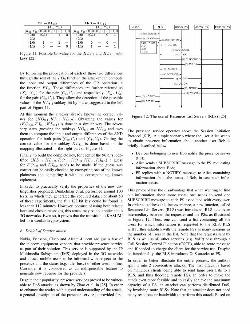
This protocol has the disadvantage that when wanting to findout information about more users, one needs to send oneSUBSCRIBE message to each PS associated with every user.In order to address this inconvenience, a new function, calledResource List Servers (RLS) was introduced. RLS acts as anintermediary between the requester and the PSs, as illustratedin Figure 12. Thus, one can send a list containing all theusers for which information is requested to the RLS. RLSwill further establish with the remote PSs as many sessions asthe number of users in the list. Note that the requests sent byRLS as well as all other services (e.g. VoIP) pass through aCall Session Control Function (CSCF), able to route messageand if needed to charge the client for the service use. Despiteits functionality, the RLS introduces DoS attacks to PS.
In order to better illustrate the entire process, the authorssplit it into 2 consecutive attacks. The first attack is basedon malicious clients being able to send large user lists to aRLS, and thus flooding remote PSs. In order to make theattack even more feasible and to easily achieve the maximumcapacity of a PS, an attacker can perform distributed DoS,by involving more RLSs. Note that an attacker does not needmany resources or bandwidth to perform this attack. Based on
the following set of assumptions:
• an online presence service client generates between 2 and8 messages per hour;
• a total of N = 106 users exist;• a PS needs to use 80% of its capacity in order to support
the maximum number of requests possible at one moment(8*N messages)
the authors computed that less than 14 malicious clients areneeded in order to congest a PS.
The second attack exploits the time mechanisms after which amessage is retransmitted in case that a user did not receive therequested response. The SIP protocol defines in this sense twotimers: T1 and T2. Supposing that after T1 seconds a responsehas not been received yet by the user, then another message isretransmitted and T1 takes the value of MIN(2 ∗ T1, T2). T2is here the maximum response delay for a transaction (4s). Ifafter 32 seconds from transmitting the first request no responseis received yet, the client agent re-sends the request 10 moretimes in an interval of 32 seconds.
Thus, if a PS is flooded as explained in the first attack, theCSCF may get also congested (remember that all the trafficfrom/to a PS passes through CSCF). Considering this, benignclients may not be able to access any other application behindthe CSCF.
In order to protect against these attacks, Zhao et al. proposed adefense mechanism which is based on: monitoring the systemresources (e.g. CPU usage, bandwidth, etc.) at a fixed smalltime interval (e.g. 0.2s), detecting the change-point of thestochastic characteristic of the measured values (note that theexistence of such a point indicates a DoS attack), identifyingthe ID of the malicious clients and finally, blocking them.
Note that the attack described here is not the only DoSattack proposed in literature. Another low-rate low-volumeDoS attack on 3G networks has been introduced by Lee etal. in [26]. The attack referred as ”signalling attack” exploitsthe unique vulnerabilities of the signalling/control plane in3G wireless networks. However, it does not address the chainreaction problem described in [25], this being the reason whywe chose to describe the attack by Zhao et al.
C. Side-channel attack
This section presents in detail a cache-timing attack on theSNOW 3G stream cipher by Brumley et al. [27]. The attackcan recover the full cipher state in seconds, without the need-ing any known keystreams. The attack is based on empiricaltiming data and has a low complexity.
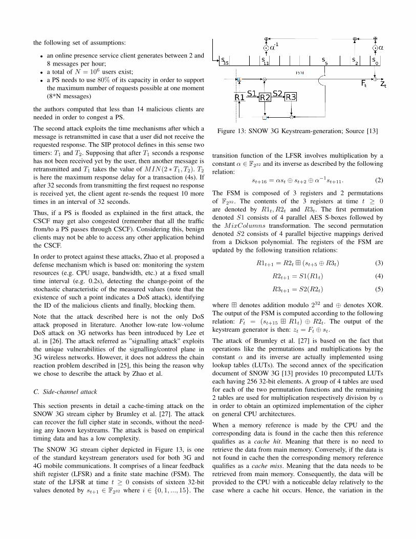
The SNOW 3G stream cipher depicted in Figure 13, is oneof the standard keystream generators used for both 3G and4G mobile communications. It comprises of a linear feedbackshift register (LFSR) and a finite state machine (FSM). Thestate of the LFSR at time t ≥ 0 consists of sixteen 32-bitvalues denoted by st+1 ∈ F232 where i ∈ {0, 1, ..., 15}. The
Figure 13: SNOW 3G Keystream-generation; Source [13]
transition function of the LFSR involves multiplication by aconstant α ∈ F232 and its inverse as described by the followingrelation:
st+16 = αst ⊕ st+2 ⊕ α−1st+11. (2)
The FSM is composed of 3 registers and 2 permutationsof F232 . The contents of the 3 registers at time t ≥ 0are denoted by R1t, R2t and R3t. The first permutationdenoted S1 consists of 4 parallel AES S-boxes followed bythe MixColumns transformation. The second permutationdenoted S2 consists of 4 parallel bijective mappings derivedfrom a Dickson polynomial. The registers of the FSM areupdated by the following transition relations:
R1t+1 = R2t � (st+5 ⊕R3t) (3)
R2t+1 = S1(R1t) (4)
R3t+1 = S2(R2t) (5)
where � denotes addition modulo 232 and ⊕ denotes XOR.The output of the FSM is computed according to the followingrelation: Ft = (st+15 � R1t) ⊕ R2t. The output of thekeystream generator is then: zt = Ft ⊕ st.The attack of Brumley et al. [27] is based on the fact thatoperations like the permutations and multiplications by theconstant α and its inverse are actually implemented usinglookup tables (LUTs). The second annex of the specificationdocument of SNOW 3G [13] provides 10 precomputed LUTseach having 256 32-bit elements. A group of 4 tables are usedfor each of the two permutation functions and the remaining2 tables are used for multiplication respectively division by αin order to obtain an optimized implementation of the cipheron general CPU architectures.
When a memory reference is made by the CPU and thecorresponding data is found in the cache then this referencequalifies as a cache hit. Meaning that there is no need toretrieve the data from main memory. Conversely, if the data isnot found in cache then the corresponding memory referencequalifies as a cache miss. Meaning that the data needs to beretrieved from main memory. Consequently, the data will beprovided to the CPU with a noticeable delay relatively to thecase where a cache hit occurs. Hence, the variation in the
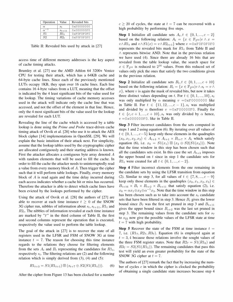
Operation Value Revealed bitsα st 0xF0000000α−1 st+11 0x000000F0S1 R1t 0xF0F0F0F0S2 R2t 0xF0F0F0F0
Table II: Revealed bits used by attack in [27]
access time of different memory addresses is the key aspectof cache timing attacks.
Brumley et al. [27] use the AMD Athlon 64 3200+ VeniceCPU for testing their attack, which has a 64KB cache and64-byte cache lines. Since each of the previously mentionedLUTs occupy 1KB, they span over 16 cache lines. Each linecontains 16 4-byte values from a LUT, meaning that the offsetis indicated by the 4 least significant bits of the value used forthe lookup. The timing variations of cache memory accessesused in the attack will indicate only the cache line that wasaccessed, and not the offset of the element in that line. Hence,only the 4 most significant bits of the value used for the lookupare revealed for each LUT.
Revealing the line of the cache which is accessed by a tablelookup is done using the Prime and Probe trace-driven cachetiming attack of Osvik et al. [28] who use it to attack the AESblock cipher [14] implementations in OpenSSL [29]. We willexplain the basic intuition of their attack next. For simplicity,assume that the lookup tables used by the cryptographic cipherare allocated contiguously and their starting address is known.First the attacker allocates a contiguous byte array denoted Awith random elements that will be used to fill the cache. Inorder to fill the cache the attacker needs to uninterruptedly reada value from every memory block of A. Then trigger the ciphersuch that it will perform table lookups. Finally, every memoryblock of A is read again and the time delay incurred duringeach access indicates whether a cache hit or miss has occurred.Therefore the attacker is able to detect which cache lines havebeen evicted by the lookups performed by the cipher.
Using the attack of Osvik et al. [28] the authors of [27] areable to recover at each time instance t ≥ 0 of the SNOW3G cipher run, nibbles of information about st, st+11, R1t andR2t. The nibbles of information revealed at each time instanceare marked by ”F” in the third column of Table II, the firstand second columns represent the operation that is executed,respectively the value used to perform the table lookup.
The goal of the attack in [27] is to recover the state of allregisters used in the LFSR and FSM of SNOW 3G at timeinstance t = 7. The reason for choosing this time instanceregards to the relations they choose for filtering elementsfrom the sets At and Bt representing the candidates for R1t,respectively st. The filtering relations are (2) and the followingrelation which is simply derived from (3), (4) and (5):
R1t+3 = S1(R1t+1)� (st+7 ⊕ S2(S1(R1t))). (6)
After the cipher from Figure 13 has been clocked for a number
c ≥ 20 of cycles, the state at t = 7 can be recovered with ahigh probability by performing five steps.
Step 1 Initialize all candidate sets At, t ∈ {0, 1, ..., c − 2}based on the following relation: At = {x ∈ F232 |v ∧ x =v∧R1t and v∧S1(x) = v∧R2t+1} where v =0xF0F0F0F0represents the revealed bits mask for R1t from Table II and∧ represents bitwise AND. Note that in the previous relationwe have used (4). Since there are already 16 bits that arerevealed from the table lookup value, the search space forx ∈ F232 is reduced to 216 values. From this reduced set ofvalues only pick the ones that satisfy the two conditions givenin the previous relation.
Step 2 Initialize all candidate sets Bt, t ∈ {0, 1, ..., c + 10}based on the following relation: Bt = {x ∈ F232 |v ∧ st = v ∧x}, where v is again the mask of revealed bits, but now it takesthree distinct values depending on t. For t ∈ {0, 1, ..., 10}, stwas only multiplied by α meaning v =0xF0000000 likein Table II. For t ∈ {11, 12, ..., c − 1}, st was multipliedand divided by α therefore v =0xF00000F0. Finally fort ∈ {c, c + 1, ..., c + 10}, st was only divided by α hence,v =0x000000F0. like in Table II.
Step 3 Filter incorrect candidates from the sets computed insteps 1 and 2 using equation (6). By iterating over all values oft ∈ {0, 1, ..., c−5} keep only those elements in the quadruples(x0, x1, x2, x3) ∈ At+3 × At+1 × Bt+7 × At which satisfyequation (6), i.e. x0 = S1(x1) � (x2 ⊕ S2(S1(x3))). Notethat the time window in this step has been chosen such thatall the candidates sets exist. In this case the set At+3 imposesthe upper bound on t since in step 1 the candidate sets forR1t were created for all t ∈ {0, 1, ..., c− 2}.Step 4 Filter incorrect elements from the one remaining inthe candidate sets by using the LFSR transition from equation(2). Similar to step 3, for all values of t ∈ {7, 8, ..., c − 9}keep only those elements in the quadruples (x0, x1, x2, x3) ∈Bt+16 × Bt × Bt+2 × Bt+11 that satisfy equation (2), i.e.x0 = αx1⊕x2⊕α−1x3. Note that the time window in this stephas been chosen such as to take into account the st candidatesets that have been filtered in step 3. Hence Bt gives the lowerbound since B7 was the first set pruned in step 3 and Bt+11
gives the upper bound since Bc+2 was the last set pruned instep 3. The remaining values from the candidate sets for s7to s22 now give the possible values of the LFSR state at timet = 7 with high probability.
Step 5 Recover the state of the FSM at time instance t =7, i.e. (R17, R27, R37). Equation (6) is employed again att = 3, 4 because those relations involve the sought values ofthe three FSM register states. Note that R27 = S1(R16) andR37 = S2(S1(R15)). The remaining candidates that pass thistest will yield an even greater probability for the state of theSNOW 3G cipher at t = 7.
The authors of [27] remark the fact that by increasing the num-ber of cycles c in which the cipher is clocked the probabilityof obtaining a single candidate state increases because step 4
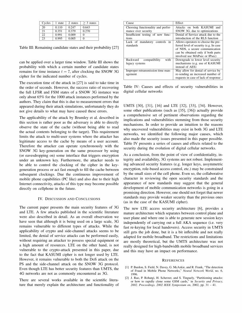
Cycles 1 state 2 states ≥ 3 states20 0.110 0.247 0.64321 0.351 0.379 0.27022 0.991 0.009 023 0.995 0.005 0
Table III: Remaining candidate states and their probability [27]
can be applied over a larger time window. Table III shows theprobability with which a certain number of candidate statesremains for time instance t = 7, after clocking the SNOW 3Gcipher for the indicated number of cycles.
The execution time of the attack in [27] is said to take time inthe order of seconds. However, the success ratio of recoveringthe full LFSR and FSM states of a SNOW 3G instance wasonly about 65% for the 1000 attack instances performed by theauthors. They claim that this is due to measurement errors thatappeared during their attack simulations, unfortunately they donot give details to what may have caused these errors.
The applicability of the attack by Brumley et al. described inthis section is rather poor as the adversary is able to directlyobserve the state of the cache (without being able to readthe actual contents belonging to the target). This requirementlimits the attack to multi-user systems where the attacker haslegitimate access to the cache by means of a user account.Therefore the attacker can operate synchronously with theSNOW 3G key-generation on the same processor by using(or eavesdropping on) some interface that triggers encryptionunder an unknown key. Furthermore, the attacker needs tobe able to control the clocking of the cipher in the key-generation process or act fast enough to fill the cache betweensubsequent clockings. Due the continuous improvement ofmobile phone capabilities (PC like) and also due to their highInternet connectivity, attacks of this type may become possibledirectly on cellphone in the future.
IV. DISCUSSION AND CONCLUSIONS
The current paper presents the main security features of 3Gand LTE. A few attacks published in the scientific literaturewere also described in detail. As an overall observation wehave seen that although it is being used on a large scale, 3Gremains vulnerable to different types of attacks. While theapplicability of crypto and side-channel attacks seems to belimited, the denial of service attacks can be performed easily,without requiring an attacker to possess special equipment ora high amount of resources. LTE on the other hand, is notvulnerable to the crypto-attack presented in this paper, dueto the fact that KASUMI cipher is not longer used by LTE.However, it remains vulnerable to both the DoS attack on thePS and the side-channel attack on the SNOW 3G protocol.Even though LTE has better security features than UMTS, the4G networks are not as commonly encountered as 3G.
There are several works available in the scientific litera-ture that merely explain the architecture and functionality of
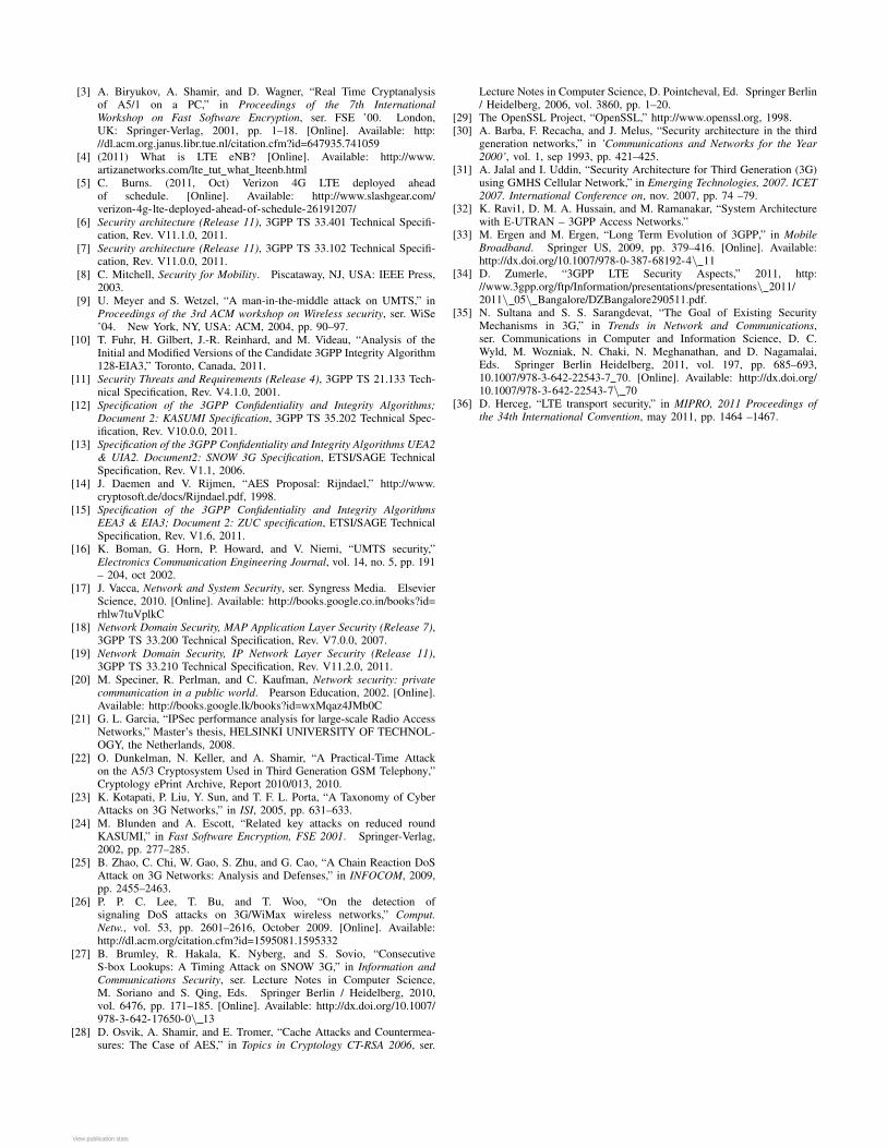
Cause EffectChoosing functionality and perfor-mance over security
Attacks on both KASUMI andSNOW 3G, due to optimizations
Insufficient testing of new func-tions
Denial of Service attack due to theintroduction of the RLS function
Lack of mandatory controls instandards
Allows operators to choose the pre-ferred level of security (e.g. In caseof NDS, a secure communicationcan be obtained only if both partsinvolved use MAPsec or IPsec)
Backward compatibility withlegacy systems
Downgrade to lower level securitymechanisms (e.g. use of KASUMIinstead of AES)
Improper retransmission time man-agement
May allow for denial of service byre-sending an increased number ofrequests in case of lack of response
Table IV: Causes and effects of security vulnerabilities indigital cellular networks
UMTS [30], [31], [16] and LTE [32], [33], [34]. However,some other publications (such as [35], [36]) actually providea comprehensive set of pertinent observations regarding theimplications and vulnerabilities stemming from those securitymechanisms. In order to provide an intuition to the reasonswhy uncovered vulnerabilities may exist in both 3G and LTEnetworks, we identified the following major causes, whichalso made the security issues presented in this paper possible.Table IV presents a series of causes and effects related to thesecurity during the evolution of digital cellular networks.
As a conclusion, from the point of view of confidentiality, in-tegrity and availability, 3G systems are not robust. Implement-ing advanced security features (e.g. longer keys, assymmetricencryption, role-based access control, etc.) may be constrainedby the small sizes of the cell phone. Even so, the collaborativecharacter in reviewing the open security standards and theappearance of new standards may suggest that the generaldevelopment of mobile communication networks is going in apromising direction. However, one should not forget that newerstandards may provide weaker security than the previous ones(as in the case of the KASUMI cipher).
The new LTE access security architecture [6], provides amature architecture which separates between control plane anduser plane and where one is able to generate new session keysindependently of carrying out a full AKA sequence (i.e. veryfast re-keying for local handovers). Access security in UMTSstill gets the job done, but it is a bit inflexible and not reallyadapted for mobile broadband. The restrictions and limitationsare mostly theoretical, but the UMTS architecture was notreally designed for high-bandwidth mobile broadband servicesand this may have an impact on performance.
REFERENCES
[1] P. Bardon, S. Field, N. Davey, G. McAskie, and R. Frank, “The detectionof Fraud in Mobile Phone Networks,” Neural Network World, no. 6,1996.
[2] J. Rao, P. Rohatgi, H. Scherzer, and S. Tinguely, “Partitioning attacks:or how to rapidly clone some GSM cards,” in Security and Privacy,2002. Proceedings. 2002 IEEE Symposium on, 2002, pp. 31 – 41.
[3] A. Biryukov, A. Shamir, and D. Wagner, “Real Time Cryptanalysisof A5/1 on a PC,” in Proceedings of the 7th InternationalWorkshop on Fast Software Encryption, ser. FSE ’00. London,UK: Springer-Verlag, 2001, pp. 1–18. [Online]. Available: http://dl.acm.org.janus.libr.tue.nl/citation.cfm?id=647935.741059
[4] (2011) What is LTE eNB? [Online]. Available: http://www.artizanetworks.com/lte tut what lteenb.html
[5] C. Burns. (2011, Oct) Verizon 4G LTE deployed aheadof schedule. [Online]. Available: http://www.slashgear.com/verizon-4g-lte-deployed-ahead-of-schedule-26191207/
[6] Security architecture (Release 11), 3GPP TS 33.401 Technical Specifi-cation, Rev. V11.1.0, 2011.
[7] Security architecture (Release 11), 3GPP TS 33.102 Technical Specifi-cation, Rev. V11.0.0, 2011.
[8] C. Mitchell, Security for Mobility. Piscataway, NJ, USA: IEEE Press,2003.
[9] U. Meyer and S. Wetzel, “A man-in-the-middle attack on UMTS,” inProceedings of the 3rd ACM workshop on Wireless security, ser. WiSe’04. New York, NY, USA: ACM, 2004, pp. 90–97.
[10] T. Fuhr, H. Gilbert, J.-R. Reinhard, and M. Videau, “Analysis of theInitial and Modified Versions of the Candidate 3GPP Integrity Algorithm128-EIA3,” Toronto, Canada, 2011.
[11] Security Threats and Requirements (Release 4), 3GPP TS 21.133 Tech-nical Specification, Rev. V4.1.0, 2001.
[12] Specification of the 3GPP Confidentiality and Integrity Algorithms;Document 2: KASUMI Specification, 3GPP TS 35.202 Technical Spec-ification, Rev. V10.0.0, 2011.
[13] Specification of the 3GPP Confidentiality and Integrity Algorithms UEA2& UIA2. Document2: SNOW 3G Specification, ETSI/SAGE TechnicalSpecification, Rev. V1.1, 2006.
[14] J. Daemen and V. Rijmen, “AES Proposal: Rijndael,” http://www.cryptosoft.de/docs/Rijndael.pdf, 1998.
[15] Specification of the 3GPP Confidentiality and Integrity AlgorithmsEEA3 & EIA3; Document 2: ZUC specification, ETSI/SAGE TechnicalSpecification, Rev. V1.6, 2011.
[16] K. Boman, G. Horn, P. Howard, and V. Niemi, “UMTS security,”Electronics Communication Engineering Journal, vol. 14, no. 5, pp. 191– 204, oct 2002.
[17] J. Vacca, Network and System Security, ser. Syngress Media. ElsevierScience, 2010. [Online]. Available: http://books.google.co.in/books?id=rhlw7tuVplkC
[18] Network Domain Security, MAP Application Layer Security (Release 7),3GPP TS 33.200 Technical Specification, Rev. V7.0.0, 2007.
[19] Network Domain Security, IP Network Layer Security (Release 11),3GPP TS 33.210 Technical Specification, Rev. V11.2.0, 2011.
[20] M. Speciner, R. Perlman, and C. Kaufman, Network security: privatecommunication in a public world. Pearson Education, 2002. [Online].Available: http://books.google.lk/books?id=wxMqaz4JMb0C
[21] G. L. Garcia, “IPSec performance analysis for large-scale Radio AccessNetworks,” Master’s thesis, HELSINKI UNIVERSITY OF TECHNOL-OGY, the Netherlands, 2008.
[22] O. Dunkelman, N. Keller, and A. Shamir, “A Practical-Time Attackon the A5/3 Cryptosystem Used in Third Generation GSM Telephony,”Cryptology ePrint Archive, Report 2010/013, 2010.
[23] K. Kotapati, P. Liu, Y. Sun, and T. F. L. Porta, “A Taxonomy of CyberAttacks on 3G Networks,” in ISI, 2005, pp. 631–633.
[24] M. Blunden and A. Escott, “Related key attacks on reduced roundKASUMI,” in Fast Software Encryption, FSE 2001. Springer-Verlag,2002, pp. 277–285.
[25] B. Zhao, C. Chi, W. Gao, S. Zhu, and G. Cao, “A Chain Reaction DoSAttack on 3G Networks: Analysis and Defenses,” in INFOCOM, 2009,pp. 2455–2463.
[26] P. P. C. Lee, T. Bu, and T. Woo, “On the detection ofsignaling DoS attacks on 3G/WiMax wireless networks,” Comput.Netw., vol. 53, pp. 2601–2616, October 2009. [Online]. Available:http://dl.acm.org/citation.cfm?id=1595081.1595332
[27] B. Brumley, R. Hakala, K. Nyberg, and S. Sovio, “ConsecutiveS-box Lookups: A Timing Attack on SNOW 3G,” in Information andCommunications Security, ser. Lecture Notes in Computer Science,M. Soriano and S. Qing, Eds. Springer Berlin / Heidelberg, 2010,vol. 6476, pp. 171–185. [Online]. Available: http://dx.doi.org/10.1007/978-3-642-17650-0\ 13
[28] D. Osvik, A. Shamir, and E. Tromer, “Cache Attacks and Countermea-sures: The Case of AES,” in Topics in Cryptology CT-RSA 2006, ser.
Lecture Notes in Computer Science, D. Pointcheval, Ed. Springer Berlin/ Heidelberg, 2006, vol. 3860, pp. 1–20.
[29] The OpenSSL Project, “OpenSSL,” http://www.openssl.org, 1998.[30] A. Barba, F. Recacha, and J. Melus, “Security architecture in the third
generation networks,” in ’Communications and Networks for the Year2000’, vol. 1, sep 1993, pp. 421–425.
[31] A. Jalal and I. Uddin, “Security Architecture for Third Generation (3G)using GMHS Cellular Network,” in Emerging Technologies, 2007. ICET2007. International Conference on, nov. 2007, pp. 74 –79.
[32] K. Ravi1, D. M. A. Hussain, and M. Ramanakar, “System Architecturewith E-UTRAN – 3GPP Access Networks.”
[33] M. Ergen and M. Ergen, “Long Term Evolution of 3GPP,” in MobileBroadband. Springer US, 2009, pp. 379–416. [Online]. Available:http://dx.doi.org/10.1007/978-0-387-68192-4\ 11
[34] D. Zumerle, “3GPP LTE Security Aspects,” 2011, http://www.3gpp.org/ftp/Information/presentations/presentations\ 2011/2011\ 05\ Bangalore/DZBangalore290511.pdf.
[35] N. Sultana and S. S. Sarangdevat, “The Goal of Existing SecurityMechanisms in 3G,” in Trends in Network and Communications,ser. Communications in Computer and Information Science, D. C.Wyld, M. Wozniak, N. Chaki, N. Meghanathan, and D. Nagamalai,Eds. Springer Berlin Heidelberg, 2011, vol. 197, pp. 685–693,10.1007/978-3-642-22543-7 70. [Online]. Available: http://dx.doi.org/10.1007/978-3-642-22543-7\ 70
[36] D. Herceg, “LTE transport security,” in MIPRO, 2011 Proceedings ofthe 34th International Convention, may 2011, pp. 1464 –1467.
View publication statsView publication stats