Embed Size (px)
Citation preview

Dimensions in millimeters (inch) unless otherwise statedwww.southco.com/EA-A01
Other options available. For complete details on variety, part numbers, installation and specification, go to
Existing BuildingSecurity System
Existing BusinessAccess Credential
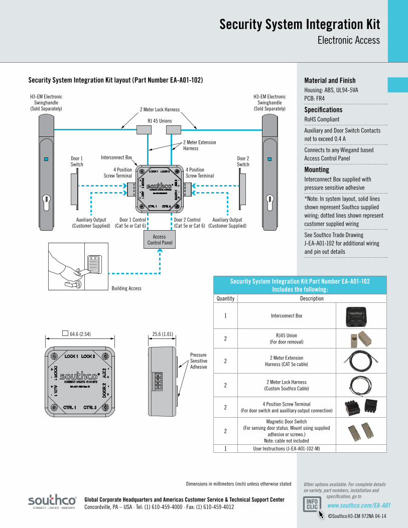
• Simplifieswiringbetween datacenterracksand remoteaccesscontrol panels• ConnectsSouthcoH3-EM ElectronicSwinghandleto existingaccesscontrol system• Facilitatesbothremote controlandmonitoringof H3-EMElectronic Swinghandle• Cabinetlevelcables,door switches,andconnectors includedinkit• Systemintegrationusing standardstructuredcabling
SecuritySystemIntegrationKitElectronic Access
The EA-A01 Security System Integration Kit simplifies the cabling and connections necessary between Southco’s H3-EM Electronic Swinghandle with integrated card reader, and any Wiegand based access control system. The Integration Kit provides a complete turnkey solution that offers a simple, cost effective way to control and monitor access at the rack level within the data center. When integrated with an existing access control system, the new Integration Kit facilitates complete remote control and monitoring from building and room access down to server door access, which demonstrates compliance with regulatory requirements such as HIPAA, HITECH, PCI DSS and Sarbanes-Oxley.
Door Switch 1
Door Switch 2
Door 1 Ctrl
Door 2 Ctrl
Existing Building Access Control System
Building Access
Wiegand output
Wiegand output
RJ45 Union (for easy door removal)
Interconnect Box
RJ45 Union (for easy door removal)
H3-EM Electronic Swinghandle
H3-EM Electronic Swinghandle
SecuritySystemIntegrationKitElectronic Access
Dimensions in millimeters (inch) unless otherwise stated
MaterialandFinishHousing: ABS, UL94-5VA PCB: FR4
SpecificationsRoHS Compliant
Auxiliary and Door Switch Contacts not to exceed 0.4 A
Connects to any Wiegand based Access Control Panel
MountingInterconnect Box supplied with pressure sensitive adhesive
*Note: In system layout, solid lines shown represent Southco supplied wiring; dotted lines shown represent customer supplied wiring
See Southco Trade Drawing J-EA-A01-102 for additional wiring and pin out details
SecuritySystemIntegrationKitPartNumberEA-A01-102Includesthefollowing:
Quantity Description
1 Interconnect Box
2 RJ45 Union (For door removal)
2 2 Meter Extension Harness (CAT 5e cable)
2 2 Meter Lock Harness (Custom Southco Cable)
2 4 Position Screw Terminal (For door switch and auxilliary output connection)
2
Magnetic Door Switch (For sensing door status. Mount using supplied
adhesive or screws.) Note: cable not included
1 User Instructions (J-EA-A01-102-M)
64.6 (2.54)
RJ 45 Unions
2 Meter Lock Harness
2 Meter Extension Harness
Access Control Panel
H3-EM ElectronicSwinghandle
(Sold Separately)
H3-EM ElectronicSwinghandle
(Sold Separately)
Auxiliary Output(Customer Supplied)
Door 2 Control(Cat 5e or Cat 6)
Building Access
Pressure Sensitive Adhesive
Door 1 Control(Cat 5e or Cat 6)
Auxiliary Output(Customer Supplied)
4 PositionScrew Terminal
Interconnect Box
4 PositionScrew Terminal
Door 2Switch
Door 1Switch
25.6 (1.01)
GlobalCorporateHeadquartersandAmericasCustomerService&TechnicalSupportCenter Concordville, PA – USA · Tel: (1) 610-459-4000 · Fax: (1) 610-459-4012 www.southco.com/EA-A01
©Southco H3-EM 972NA 04-14
Other options available. For complete details on variety, part numbers, installation and specification, go to
SecuritySystemIntegrationKitlayout(PartNumberEA-A01-102)
별도의 언급이 없는 한 규격들은 밀리미터 로 표시합니다www.southco.com/EA-A06
-+
기타 옵션들 가능함. 변형품, 제품번호, 설치 및 사양에 관한 내용은 다음 사이트를 참고 하십시오.
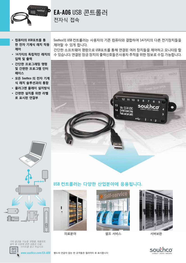
USB 컨트롤러는 다양한 산업분야에 응용됩니다.
셀프 서비스 서버보완의료분야
• 컴퓨터의 USB포트를 통한 전자 기계식 래치 작동제어
• 14가지의 독립적인 래치의 입력 및 출력
• 간단한 프로그래밍 명령 및 간편한 프로그램 인터페이스
• 모든 Southco 의 전자 기계식 래치 솔루션과의 통합
• 플러그앤 플레이 설치방식
• 간편한 설치를 위한 라벨로 표시된 연결부
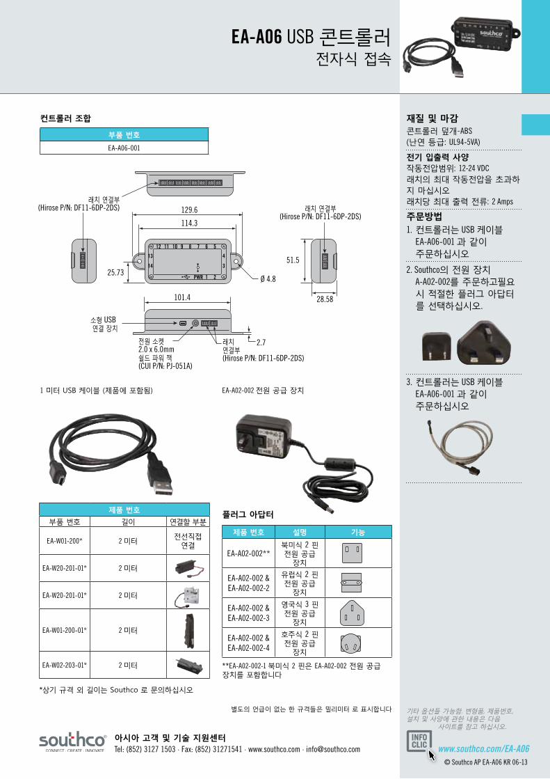
EA-A06 USB 콘트롤러전자식 접속
Southco의 USB 컨트롤러는 사용자의 기존 컴퓨터와 결합하여 14가지의 다른 전기장치들을 제어할 수 있게 합니다.
간단한 소프트웨어 명령으로 USB포트를 통해 연결된 여러 장치들을 제어하고 모니터링 할 수 있습니다. 연결된 잠금 장치의 출력신호들은사용자 추적을 위한 정보로 수집 가능합니다.
© Southco NA MINI-EK 0510
별도의 언급이 없는 한 규격들은 밀리미터 로 표시합니다 기타 옵션들 가능함. 변형품, 제품번호, 설치 및 사양에 관한 내용은 다음 사이트를 참고 하십시오.
아시아 고객 및 기술 지원센터Tel: (852) 3127 1503 · Fax: (852) 31271541 · www.southco.com · [email protected] www.southco.com/EA-A06
© Southco AP EA-A06 KR 06-13
129.6
12 11 10 9 8 7 6 5
1PWR 2
4
3
13
14
114.3
101.4
Ø 4.8
2.7
28.58
25.73
래치 연결부(Hirose P/N: DF11-6DP-2DS)
래치 연결부(Hirose P/N: DF11-6DP-2DS)
소형 USB 연결 장치
래치 연결부(Hirose P/N: DF11-6DP-2DS)
전원 소켓2.0 x 6.0mm 쉴드 파워 잭(CUI P/N: PJ-051A)
51.5
제품 번호
부품 번호 길이 연결할 부분
EA-W01-200* 2 미터전선직접
연결
EA-W20-201-01* 2 미터
EA-W20-201-01* 2 미터
EA-W01-200-01* 2 미터
EA-W02-203-01* 2 미터
부품 번호
EA-A06-001
재질 및 마감콘트롤러 덮개-ABS (난연 등급: UL94-5VA)
전기 입출력 사양 작동전압범위: 12-24 VDC 래치의 최대 작동전압을 초과하지 마십시오 래치당 최대 출력 전류: 2 Amps
주문방법1. 컨트롤러는 USB 케이블 EA-A06-001 과 같이 주문하십시오
2. Southco의 전원 장치 A-A02-002를 주문하고필요 시 적절한 플러그 아답터 를 선택하십시오.
3. 컨트롤러는 USB 케이블 EA-A06-001 과 같이 주문하십시오
EA-A06 USB 콘트롤러전자식 접속
EA-A02-002 전원 공급 장치
컨트롤러 조합
**EA-A02-002-1 북미식 2 핀은 EA-A02-002 전원 공급 장치를 포함합니다
*상기 규격 외 길이는 Southco 로 문의하십시오
1 미터 USB 케이블 (제품에 포함됨)
제품 번호 설명 기능
EA-A02-002**북미식 2 핀 전원 공급
장치
EA-A02-002 & EA-A02-002-2
유럽식 2 핀 전원 공급
장치
EA-A02-002 & EA-A02-002-3
영국식 3 핀 전원 공급
장치
EA-A02-002 & EA-A02-002-4
호주식 2 핀 전원 공급
장치
플러그 아답터

www.southco.com Dimensions in millimeters (inch) unless otherwise stated
Other options available. For complete details on variety, part numbers, installation and specification, go to
TOUCH ACCESSSTATUS OPEN
• Simplifiedone-touch keymanagement andlockactuation• Minimalpower consumptionidealfor batterypowered applications• Simple,software-free installation• Keyfobsavailablewith customcolorsandlogos• LEDprovidesvisual feedbackforprogramming andaccessstatus• Sealed,stainlesssteel, electronickey constructionfordurability• Highsecuritywithtrillions ofpossiblekeycodes• Programmableaccess time
EAElectronic Key SystemElectronic access
The new SOUTHCO® Electronic Key System provides an efficient, user-friendly solution for key management issues. The compact iButton® based system requires no software and allows users to easily set up, modify, add and delete access privileges with the touch of a button. A user need only touch the electronic key to the reader to authenticate the key and receive access.
The Electronic Key System can operate any Southco electromechanical lock and is especially well suited for applications that require the distribution of multiple keys to individuals with varying access privileges across multiple access points – an arduous undertaking with mechanical keys.
www.southco.com
www.southco.com Dimensions in millimeters (inch) unless otherwise stated
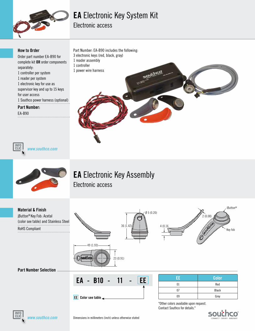
EAElectronic Key AssemblyElectronic access
EAElectronic Key System KitElectronic access
Material&FinishiButton® Key Fob: Acetal (color see table) and Stainless Steel
RoHS Compliant
PartNumberSelection
HowtoOrderOrder part number EA-B90 for complete kit OR order componentsseparately: 1 controller per system 1 reader per system 1 electronic key for use as supervisor key and up to 15 keys for user access 1 Southco power harness (optional)
PartNumber:EA-B90
Part Number: EA-B90 includes the following: 3 electronic keys (red, black, gray) 1 reader assembly 1 controller 1 power wire harness
"Other colors available upon request. Contact Southco for details."
36 (1.42)
49 (1.93)
23 (0.91)
4 (0.16
2 (0.08)
iButton®
Ø 5 (0.20)
Key fob
EA - B10 - 11 - EE
EE Colorseetable
EE Color01 Red
07 Black
09 Grey

www.southco.com
www.southco.comDimensions in millimeters (inch) unless otherwise stated
EAElectronic Key Reader AssemblyElectronic access
EAElectronic KeyController AssemblyElectronic access
Optionalpowerwireharness
Material&FinishEnclosure: ABS V-0 rated RoHS Compliant
ElectricalSpecifications:Supply Voltage: 12VDC ± 10%
Quiescent Current: 100µA (max)
Operating Current: 35mA (max)
Latch Command Output Signal Rating: 2A Max
PartNumber:EA-B20-112
Material&FinishRoHS Compliant Polyacetal plastic and chrome plated steel
InstallationPrepare panel as shown. Remove nut. Slip assembly through hole, threaded on nut. Plug connector into electronic key reader connector on controller assembly
PartNumber:EA-B30-117
9 (0.35) Max panel thickness
Ø21.5 (0.85)
2.5 (0.10)
6.5 (0.26)
M12 x 1Thread
Nut13 (0.51)
25.5 (1.0)
3.5 (0.14)
Wire
ShrinkTube
Connector
Ø11(0.43)
1000 (39.37)Wire lengthmeasurementdoes not include connector
Ø12.3(0.48 + 0.02)
+0.5-0
1 (0.04) Min panel thickness
114.3 (4.50)
51.5 (2.03)
2X Ø4.8(0.19)
29 (1.14)
Electronic Key Reader Connector (Hirose® DF11 Series)
Latch Connector (Molex® Micro-Fit 3.0 Series)Power Connector (Molex® Micro-Fit 3.0 Series)
L
2.73 (0.11)
PartNumber Length
EA-W22-100 1 m (39.37)
EA-W22-200 2 m (78.74)
www.southco.com/EA-B90© Southco EA-B NA 01-10
iButton® is a registered trademark of Maxim Integrated Products, Inc.
Other options available. For complete details on variety, part numbers, installation and specification, go to
Dimensions in millimeters (inch) unless otherwise stated
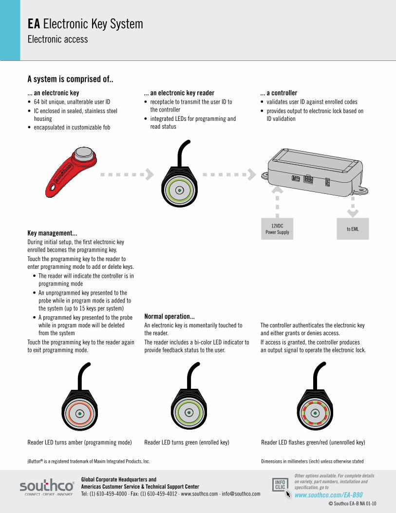
EAElectronic Key SystemElectronic access
GlobalCorporateHeadquartersandAmericasCustomerService&TechnicalSupportCenterTel: (1) 610-459-4000 · Fax: (1) 610-459-4012 · www.southco.com · [email protected]
Reader LED turns amber (programming mode) Reader LED turns green (enrolled key) Reader LED flashes green/red (unenrolled key)
12VDC Power Supply
to EML
...anelectronickey• 64 bit unique, unalterable user ID• IC enclosed in sealed, stainless steel housing • encapsulated in customizable fob
...anelectronickeyreader• receptacle to transmit the user ID to the controller• integrated LEDs for programming and read status
...acontroller• validates user ID against enrolled codes• provides output to electronic lock based on ID validation
Keymanagement...During initial setup, the first electronic key enrolled becomes the programming key. Touch the programming key to the reader to enter programming mode to add or delete keys. • The reader will indicate the controller is in programming mode • An unprogrammed key presented to the probe while in program mode is added to the system (up to 15 keys per system) • A programmed key presented to the probe while in program mode will be deleted from the systemTouch the programming key to the reader again to exit programming mode.
Normaloperation...An electronic key is momentarily touched to the reader. The reader includes a bi-color LED indicator to provide feedback status to the user.
The controller authenticates the electronic key and either grants or denies access.If access is granted, the controller produces an output signal to operate the electronic lock.
Asystemiscomprisedof..
114.3 (4.50)
51.5 (2.03)
2X Ø4.8(0.19)
29 (1.14)
Electronic Key Reader Connector (Hirose® DF11 Series)
Latch Connector (Molex® Micro-Fit 3.0 Series)Power Connector (Molex® Micro-Fit 3.0 Series)
www.southco.com/EA-K1 Dimensions in millimeters (inch) unless otherwise stated
Other options available. For complete details on variety, part numbers, installation and specification, go to
1 2 3
4 5 6
7 8 9
0 #
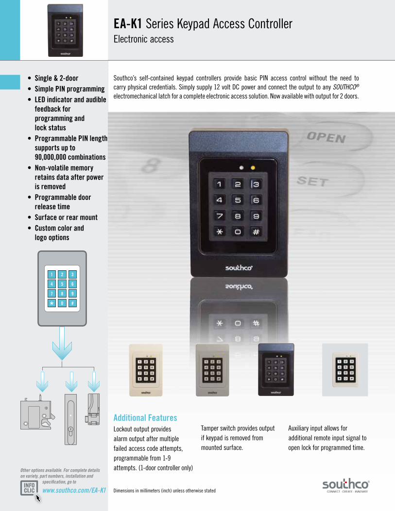
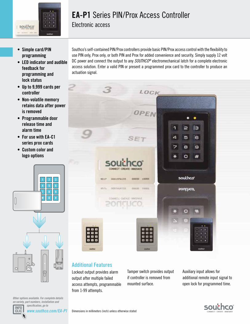
Additional FeaturesLockout output provides alarm output after multiple failed access code attempts, programmable from 1-9 attempts. (1-door controller only)
Tamper switch provides output if keypad is removed from mounted surface.
Auxiliary input allows for additional remote input signal to open lock for programmed time.
• Single & 2-door• Simple PIN programming• LED indicator and audible feedback for programming and lock status• Programmable PIN length supports up to 90,000,000 combinations • Non-volatile memory retains data after power is removed• Programmable door release time • Surface or rear mount• Custom color and logo options
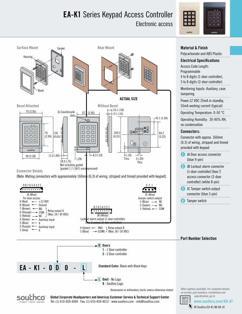
EA-K1 Series Keypad Access ControllerElectronic access
Southco’s self-contained keypad controllers provide basic PIN access control without the need to carry physical credentials. Simply supply 12 volt DC power and connect the output to any SOUTHCO® electromechanical latch for a complete electronic access solution. Now available with output for 2 doors.
ACTUAL SIZE
www.southco.com/EA-K1© Southco EA-K1 NA 08-10
JAJBJC118
(4.65)
75 (2.95) 14.1 (.56)
Gasket
Bezel
Housing
4.1 (.16)
18.9 (.75)Not including gasket (gasket 1.7 (.067) uncompressed)
11.6 (.46)58 (2.28) 4 (.16)Thru 5 (.20)
Thru
8.3 (.33)
84.2(3.32)
109.5(4.31)
42.1 (1.66)
67.7 (2.66)
7 (.28)
2x Countersunk slots
JA (Blue)For door access
9 8 7 6 5 4 3 2 1
9 (Red)8 (Black) 7 (Brown)6 (Orange) 5 (Yellow)4 (Green)3 (Blue)2 (Purple)1 (Grey)
+12 VDCGround
Auxiliary inputXAuxiliary inputX
NOCOMNC
Relay output A(Max. 2A / 30 VDC)
Relay output B(Max. 2A / 30 VDC)
4 (Green)3 (Blue)
(NO)(COM)
JB (White)Lockout alarm output (1-door controller)
Door 2 access (2-door controller)
8 7 6 5 4 3 2 1
3 (Blue)2 (Green) 1 (Yellow)
NCNOCOM
JC (Blue)tamper switch output
3 2 1
123
4
X X X X X
X X
X
76(2.99)
Dimensions in millimeters (inch) unless otherwise stated Other options available. For complete details on variety, part numbers, installation and specification, go to
Material & FinishPolycarbonate and ABS Plastic
Electrical SpecificationsAccess Code Length: Programmable 4 to 8 digits (1-door controller), 5 to 8 digits (2-door controller)
Monitoring Inputs: Auxiliary, case tampering
Power:12 VDC 25mA in standby, 55mA working current (typical)
Operating Temperature: 0-50 °C
Operating Humidity: 20-90% RH, no condensation
Connectors:Connector with approx. 160mm (6.3) of wiring, stripped and tinned provided with keypad
1 JA Door access connector (blue 9-pin)
2 JB Lockout alarm connector (1-door controller) Door 2 access connector (2-door controller) (white 8-pin)
3 JC Tamper switch output connector (blue 3-pin)
4 Tamper switch
EA-K1 Series Keypad Access ControllerElectronic access
EA - K1 - 0 D 0 - L
Part Number Selection
Bezel Attached Without Bezel
Rear MountSurface Mount
Standard Color: Black with Black Keys
D Doors 1 - 1 Door controller 2 - 2 Door controller
L Omit - No Logo 9 - Southco Logo
Global Corporate Headquarters and Americas Customer Service & Technical Support CenterTel: (1) 610-459-4000 · Fax: (1) 610-459-4012 · www.southco.com · [email protected]
Connector Details(Note: Mating connectors with approximately 160mm (6.3) of wiring, stripped and tinned provided with keypad).
Sdfsfsdfsfdsafsafsdfsff EA-K1 KeypadInstructions for Programming EA-K1-01x
J-EA-K1-01-M RevB visit www.southco.com for latest version of this document Page 1 of 4
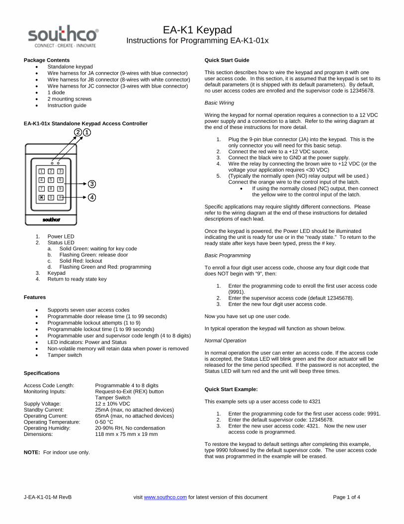
Package Contents Standalone keypad Wire harness for JA connector (9-wires with blue connector) Wire harness for JB connector (8-wires with white connector) Wire harness for JC connector (3-wires with blue connector) 1 diode 2 mounting screws Instruction guide
EA-K1-01x Standalone Keypad Access Controller
12
3
4
1 2 3
4 5 6
7 8 9
0 #
12
3
4
1 2 3
4 5 6
7 8 9
0 #
1. Power LED2. Status LED
a. Solid Green: waiting for key codeb. Flashing Green: release doorc. Solid Red: lockoutd. Flashing Green and Red: programming
3. Keypad4. Return to ready state key
Features
Supports seven user access codes Programmable door release time (1 to 99 seconds) Programmable lockout attempts (1 to 9) Programmable lockout time (1 to 99 seconds) Programmable user and supervisor code length (4 to 8 digits) LED indicators: Power and Status Non-volatile memory will retain data when power is removed Tamper switch
Specifications
Access Code Length: Programmable 4 to 8 digitsMonitoring Inputs: Request-to-Exit (REX) button
Tamper SwitchSupply Voltage: 12 ± 10% VDCStandby Current: 25mA (max, no attached devices)Operating Current: 65mA (max, no attached devices)Operating Temperature: 0-50 °COperating Humidity: 20-90% RH, No condensationDimensions: 118 mm x 75 mm x 19 mm
NOTE: For indoor use only.
Quick Start Guide
This section describes how to wire the keypad and program it with oneuser access code. In this section, it is assumed that the keypad is set to itsdefault parameters (it is shipped with its default parameters). By default,no user access codes are enrolled and the supervisor code is 12345678.
Basic Wiring
Wiring the keypad for normal operation requires a connection to a 12 VDCpower supply and a connection to a latch. Refer to the wiring diagram atthe end of these instructions for more detail.
1. Plug the 9-pin blue connector (JA) into the keypad. This is theonly connector you will need for this basic setup.
2. Connect the red wire to a +12 VDC source.3. Connect the black wire to GND at the power supply.4. Wire the relay by connecting the brown wire to +12 VDC (or the
voltage your application requires <30 VDC)5. (Typically the normally open (NO) relay output will be used.)
Connect the orange wire to the control input of the latch. If using the normally closed (NC) output, then connect
the yellow wire to the control input of the latch.
Specific applications may require slightly different connections. Pleaserefer to the wiring diagram at the end of these instructions for detaileddescriptions of each lead.
Once the keypad is powered, the Power LED should be illuminatedindicating the unit is ready for use or in the “ready state.” To return to theready state after keys have been typed, press the # key.
Basic Programming
To enroll a four digit user access code, choose any four digit code thatdoes NOT begin with “9”, then:
1. Enter the programming code to enroll the first user access code(9991).
2. Enter the supervisor access code (default 12345678).3. Enter the new four digit user access code.
Now you have set up one user code.
In typical operation the keypad will function as shown below.
Normal Operation
In normal operation the user can enter an access code. If the access codeis accepted, the Status LED will blink green and the door actuator will bereleased for the time period specified. If the password is not accepted, theStatus LED will turn red and the unit will beep three times.
Quick Start Example:
This example sets up a user access code to 4321
1. Enter the programming code for the first user access code: 9991.2. Enter the default supervisor code: 12345678.3. Enter the new user access code: 4321. Now the new user
access code is programmed.
To restore the keypad to default settings after completing this example,type 9990 followed by the default supervisor code. The user access codethat was programmed in the example will be erased.
Sdfsfsdfsfdsafsafsdfsff EA-K1 KeypadInstructions for Programming EA-K1-01x
J-EA-K1-01-M RevB visit www.southco.com for latest version of this document Page 2 of 4
Programming the Keypad
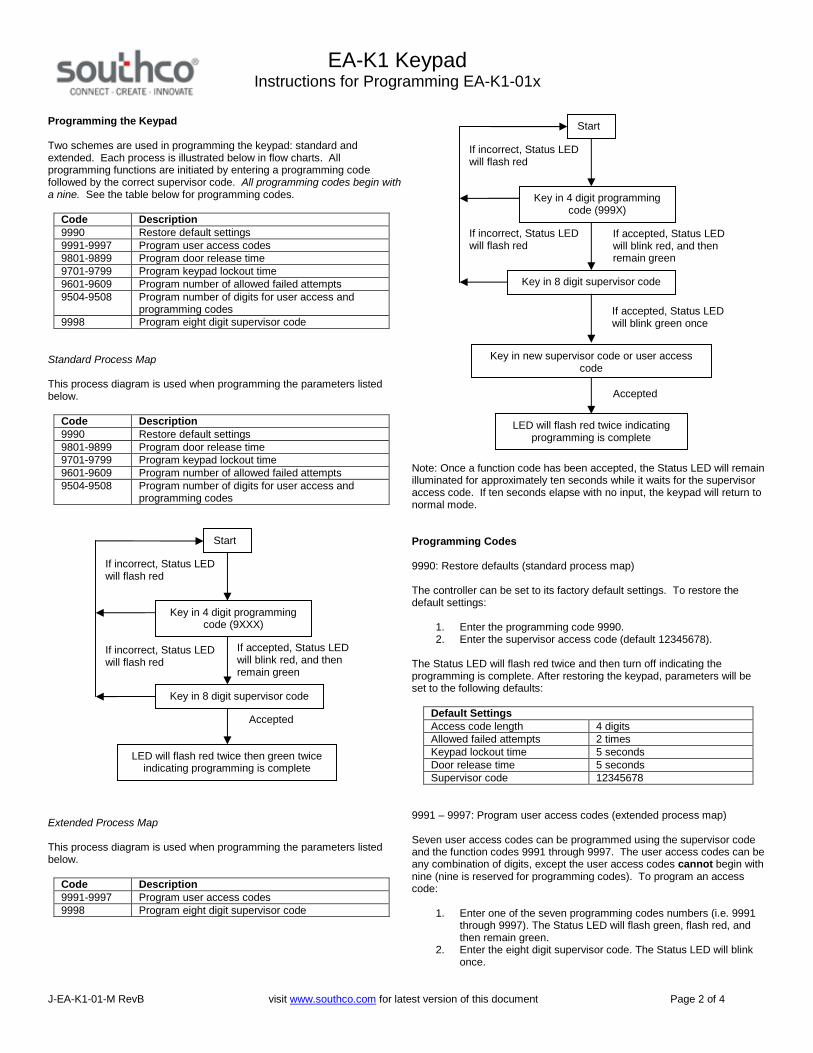
Two schemes are used in programming the keypad: standard andextended. Each process is illustrated below in flow charts. Allprogramming functions are initiated by entering a programming codefollowed by the correct supervisor code. All programming codes begin witha nine. See the table below for programming codes.
Code Description9990 Restore default settings9991-9997 Program user access codes9801-9899 Program door release time9701-9799 Program keypad lockout time9601-9609 Program number of allowed failed attempts9504-9508 Program number of digits for user access and
programming codes9998 Program eight digit supervisor code
Standard Process Map
This process diagram is used when programming the parameters listedbelow.
Code Description9990 Restore default settings9801-9899 Program door release time9701-9799 Program keypad lockout time9601-9609 Program number of allowed failed attempts9504-9508 Program number of digits for user access and
programming codes
Extended Process Map
This process diagram is used when programming the parameters listedbelow.
Code Description9991-9997 Program user access codes9998 Program eight digit supervisor code
Note: Once a function code has been accepted, the Status LED will remainilluminated for approximately ten seconds while it waits for the supervisoraccess code. If ten seconds elapse with no input, the keypad will return tonormal mode.
Programming Codes
9990: Restore defaults (standard process map)
The controller can be set to its factory default settings. To restore thedefault settings:
1. Enter the programming code 9990.2. Enter the supervisor access code (default 12345678).
The Status LED will flash red twice and then turn off indicating theprogramming is complete. After restoring the keypad, parameters will beset to the following defaults:
Default SettingsAccess code length 4 digitsAllowed failed attempts 2 timesKeypad lockout time 5 secondsDoor release time 5 secondsSupervisor code 12345678
9991 – 9997: Program user access codes (extended process map)
Seven user access codes can be programmed using the supervisor codeand the function codes 9991 through 9997. The user access codes can beany combination of digits, except the user access codes cannot begin withnine (nine is reserved for programming codes). To program an accesscode:
1. Enter one of the seven programming codes numbers (i.e. 9991through 9997). The Status LED will flash green, flash red, andthen remain green.
2. Enter the eight digit supervisor code. The Status LED will blinkonce.
Key in 4 digit programmingcode (999X)
Key in 8 digit supervisor code
LED will flash red twice indicatingprogramming is complete
Start
If incorrect, Status LEDwill flash red
If incorrect, Status LEDwill flash red
Accepted
Key in new supervisor code or user accesscode
If accepted, Status LEDwill blink red, and thenremain green
If accepted, Status LEDwill blink green once
Key in 4 digit programmingcode (9XXX)
Key in 8 digit supervisor code
LED will flash red twice then green twiceindicating programming is complete
Start
If incorrect, Status LEDwill flash red
If accepted, Status LEDwill blink red, and thenremain green
Accepted
If incorrect, Status LEDwill flash red

Sdfsfsdfsfdsafsafsdfsff EA-K1 KeypadInstructions for Programming EA-K1-01x
J-EA-K1-01-M RevB visit www.southco.com for latest version of this document Page 3 of 4
3. Enter the four digit user access code desired. The Status LEDwill flash red twice, and then turn off.
To set another user access code, use the next available programmingcode 9992, 9993, etc. To change a user access code, use theprogramming code that it is paired with. For example, if 9992 was used toassign the user access code 1234, you may change this user access codeto 4321 by using the programming code 9992. It is recommend that thesupervisor keep careful records of each user access programming code,the corresponding user access code, and the individuals who use thiscode.
9601 – 9609: Program allowed failed attempts (standard process map)
The number of allowed failed attempts can be programmed from one tonine. This is the number of times the wrong access code can be entered(this includes both user access codes and the supervisor pass code). Ifthis number is reached, the keypad will lock out all operation for thespecified lockout time. This feature is designed to prevent trial and errortampering. To change from the default of two:
1. Enter “960x” where “x” is the number of allowed failed attemptsand can range from 1 to 9. The Status LED will flash green,flash red, and then become solid green.
2. Enter the eight digit supervisor code. The Status LED will flashred, then green before turning off.
9701 – 9799: Program keypad lockout time (standard process map)
The duration of the keypad lockout time can be programmed from 1 to 99seconds. While locked out, the keys are not functional and The StatusLED is illuminated solid red.
The keypad lockout time code is 97tt, where “tt” is the desired keypadlockout time in seconds.
For example, if the desired keypad lockout time is 30 seconds, theprogramming code is 9730.
To change from the default of five seconds:
1. Enter “97tt”, where “tt” is the lockout code in seconds. The StatusLED will flash green, flash red, and then become solid green.
2. Enter the eight digit supervisor code. The Status LED will flashred, then green before turning off.
9801 – 9899: Program door release time (standard process map)
The length of time the door is released can be programmed from 1 to 99seconds.
The door release time code is 98tt, where “tt” is the desired door releasetime in seconds.
For example, if the desired door release time is one minute, theprogramming code is 9860.
To change from the default of five seconds:
1. Enter “98tt”, where “tt” is the door release code in seconds. TheStatus LED will flash green, flash red, and then become solidgreen.
2. Enter the eight digit supervisor code. The Status LED will flashred, then green before turning off.
9998: Program eight digit supervisor code (extended process map)
CAUTION: If the supervisor access code is lost, forgotten orincorrectly entered while programming, the keypad cannot be restored todefault settings, no new programming codes may be entered, and the lostsupervisor access code cannot be recovered. Without the supervisorcode, the keypad will continue to function, however no programmingchanges can be made.
Please change the eight digit code to a number you will remember. If thenumber is lost it cannot be recovered. To change the supervisor code:
1. Enter “9998”. The Status LED will flash green, blink red, andthen become solid green.
2. Enter the current eight digit supervisor code. The Status LED willblink once.
3. Carefully enter the new eight digit key code. The Status LED willflash red, then turn off.
9504 – 9508: Program number of digits for user access and programmingcodes (standard process map)
CAUTION: This is an advanced feature; it increases the complexityof programming the keypad. It is recommend only to switch from thedefault setting of four digit user access codes if absolutely necessary.
The number of digits in the user access and programming codes can bechanged from the default of four. The number of digits set here is thenumber of digits the keypad accepts for all codes, including function codes.If the number of digits is increased, then the function code must be paddedwith zeroes. For example if the number of digits has been changed to six,the code to reset the controller (9990) must be entered as “999000”. Thesupervisor code need not be adjusted; it is always an eight digit code.
NOTE: Any previously assigned user access codes will be erased whenthe number of digits is changed.
To change from the default of four digits:
1. Enter “950d”, where “d” is the number of digits in the user accesscode (ranging from 4 to 8). The Status LED will flash green,flash red, and then become solid green.
2. Enter the eight digit supervisor code. The Status LED will flashred, then green before turning off.
Other Features
Lockout Alarm (JB Connector)
The EA-K1-01x controller provides a relay output that is activatedwhenever:
the keypad is locked out due to reaching the number of allowedfailed attempts, or
the security monitor input is active
This will cause the relay to close (i.e. drive the voltage at the COMterminal) for the programmed keypad lockout time.
Auxiliary Input
The EA-K1-01x controller has an auxiliary input that can be driven by anexternal device. Pin 6 from the JA connector (green wire) is the auxiliaryinput. When the auxiliary input is 12VDC, the controller will grant accessfor the programmed access time.
Sdfsfsdfsfdsafsafsdfsff EA-K1 KeypadInstructions for Programming EA-K1-01x
J-EA-K1-01-M RevB visit www.southco.com for latest version of this document Page 4 of 4
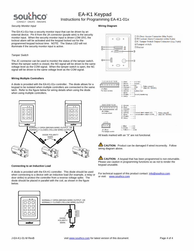
Security Monitor Input
The EA-K1-01x has a security monitor input that can be driven by anexternal device. Pin 8 from the JA connector (purple wire) is the securitymonitor input. When the security monitor input is driven LOW (0V), thelockout alarm will be activated and the keypad locked out for theprogrammed keypad lockout time. NOTE: The Status LED will notilluminate if the security monitor input is active.
Tamper Switch
The JC connector can be used to monitor the status of the tamper switch.When the tamper switch is closed, the NO signal will be driven to the samevoltage level as the COM signal. When the tamper switch is open, the NCsignal will be driven to the same voltage level as the COM signal.
Wiring Multiple Controllers
A diode is provided with the EA-K1-01x controller. The diode allows for akeypad to be isolated when multiple controllers are connected to the samelatch. Refer to the figure below for wiring details when using the diodewhen using multiple controllers.
Connecting to an Inductive Load
A diode is provided with the EA-K1 controller. This diode should be usedwhen connecting to a device with an inductive load (for example, a relay ordoor strike) to protect the controller from a reverse voltage spike. Thediode should be placed in parallel with the coil, as shown in the figurebelow.
Wiring Diagram
All leads marked with an “X” are not functional.
CAUTION: Product can be damaged if wired incorrectly. Followwiring diagram above.
CAUTION: A keypad that has been programmed is non-returnable.Please use caution in programming functions so as not to render thekeypad unusable.
For technical support of this product contact: [email protected] visit: www.southco.com
NORMALLY OPEN (BROWN WIRE) OUTPUT, ORNORMALLY CLOSED (YELLOW WIRE) OUTPUT
DIODEPOLARITY
MARK
NORMALLY OPEN (BROWN WIRE) OUTPUT, ORNORMALLY CLOSED (YELLOW WIRE) OUTPUT
DIODE POLARITYMARK

Sdfsfsdfsfdsafsafsdfsff EA-K1-02x KeypadOperating Instructions
J-EA-K1-02-M_revB visit www.southco.com for latest version of this document Page 1 of 3
Package Contents
Standalone keypad Wire harness for JA connector (9-wires with blue connector) Wire harness for JB connector (8-wires with white connector) Wire harness for JC connector (3-wires with blue connector) 1 diode 2 mounting screws Operating instructions
EA-K1 Standalone Keypad Access Controller
12
3
4
1 2 3
4 5 6
7 8 9
0 #
12
3
4
1 2 3
4 5 6
7 8 9
0 #
1. Power LED2. Status LED
a. Solid Green: waiting for key codeb. Flashing Green: release doorc. Flashing Green and Red: programming
3. Keypad4. Command exit
Features
Supports 2-latch access with 150 user access codes Programmable door release time (1 to 99 seconds) Programmable user and instruction code length (5 to 8 digits) LED indicators: Power and Status Non-volatile memory will retain data when power is removed Tamper switch For indoor use only
Specifications
Access Code Length: Programmable 5 to 8 digitsMonitoring Inputs: Auxiliary (x2)
Tamper SwitchSupply Voltage: 12 ± 10% VDCStandby Current: 25mA (max, no attached devices)Operating Current: 65mA (max, no attached devices)Operating Temperature: 0-50 °COperating Humidity: 20-90% RH, No condensationDimensions: 118 mm x 75 mm x 19 mm
Controller Mounting and Installation
Please refer to Southco trade drawing J-EA-K1-02 for mounting andinstallation details.
Modes of Operation
There are two modes of operation for this access controller:
1. User Mode – In this mode, access will be granted when a validaccess code is entered or the auxiliary input asserted. Anaccess code ending in an odd number will open the latchconnected to the JA connector. An access code ending in aneven number will open the latch connected to the JB connector.
2. Programming Mode – In this mode, the controller’s settings canbe set by the supervisor.
Types of Codes
There are three types of codes for this access controller:
1. Access Code – The controller allows for 150 user access codes.When a programmed access code is entered, the controller willgrant access. Access codes cannot begin with a “9”.
2. Supervisor Code – There is one supervisor code. This code isused to program the controller and cannot be used as an accesscode. The supervisor code cannot begin with a “9”.
3. Instruction Code – These are used to program the varioussettings of the controller. The instruction codes are listed in thetable below.
Instruction CodesProgramming the Supervisor Code 99998Enrolling or Changing Access Codes 99001 - 99150Programming Access Code Length 99505 – 99508Programming Door Release Time 99801 – 99899Resetting the Controller 99990

Sdfsfsdfsfdsafsafsdfsff EA-K1-02x KeypadOperating Instructions
J-EA-K1-02-M_revB visit www.southco.com for latest version of this document Page 2 of 3
Default Settings
Default SettingsAccess code length 5 digitsDoor release time 5 secondsSupervisor code 12345678
Programming the Supervisor Code
The controller is shipped with the default supervisor code (12345678) pre-programmed. To change the supervisor code:
1. Enter instruction code “99998”. The Status LED will flash green,blink red, and then become solid green.
2. Enter the current eight digit supervisor code. The Status LED willblink once.
3. Enter the new eight digit supervisor code. The supervisor codecannot begin with nine (nine is reserved for instruction codes).The Status LED will flash red then turn off.
WARNING: If the supervisor code is lost, forgotten or incorrectlyentered while programming, the keypad cannot be restored to defaultsettings, no new programming codes may be entered, and the lostsupervisor code cannot be recovered. Without the supervisor code, thekeypad will continue to function. However, no programming changes canbe made.
Enrolling or Changing Access Codes
The controller supports up to 150 user access codes. Access codes thatend in an odd number will allow access to the latch connected to the JAconnector. Access codes that end in an even number will allow access tothe latch connected to the JB connector.
The access codes can be any combination of digits, except the accesscodes cannot begin with nine (nine is reserved for instruction codes). Toenroll or change an access code:
1. Enter one of the 150 instruction codes for enrolling access codes(i.e. 99001 through 99150). The Status LED will flash green,flash red, and then remain green.
2. Enter the supervisor code. The Status LED will blink once.3. Enter the access code. The Status LED will flash red twice, and
then turn off.
To change a user access code, use the programming code that it is pairedwith. For example, if 99001 had been used to assign the user access code12345, you may change this user access code to 54321 by using theinstruction code 99001. It is recommended that the supervisor keepcareful records of each access code and its corresponding instructioncode.
Programming Door Release Time
The length of time the door is released can be programmed from 1 to 99seconds.
To change from the default of five seconds:
1. Enter “998tt”, where “tt” is the door release code in seconds.The Status LED will flash green, flash red, and then becomesolid green.
2. Enter the supervisor code. The Status LED will flash red, thengreen before turning off.
Programming Code Length
The number of digits in the access and instruction codes can be changedfrom the default of five. The number of digits set here is the number ofdigits the keypad accepts for both access and instruction codes. If thenumber of digits is increased, then the function code must be padded withzeroes. For example if the number of digits has been changed from five toeight, the code to reset the controller (99990) must be entered as“99990000”.
NOTE: The supervisor code cannot be adjusted; it is always an eight digitcode.
To change from the default of five digits:
1. Enter “9950x”, where “x” is the number of digits in the useraccess code (ranging from 5 to 8). The Status LED will flashgreen, flash red, and then become solid green.
2. Enter the eight digit supervisor code. The Status LED will flashred, then green before turning off.
NOTE: Changing the code length will not delete programmed accesscodes. However, changing the code length to be longer than access codesalready stored in memory will result in the access codes being unusable.For example, if a five digit access code is stored in memory, and the codelength is then changed to eight, the access code cannot be used.
If the code length is changed to be shorter than access codes alreadyenrolled, then the last digit of the shortened access code will determinewhich latch is opened. For example, if an access code is 87654321, thecontroller will open the latch connected to the JA connector since theaccess code ends in an odd digit. If the code length is changed to sevendigits, then this access code will be shortened to 8765432 and open thelatch connected to the JB connector since the access code now ends in aneven digit
Resetting the Controller
The controller can be set to its factory default settings. To restore thedefault settings:

Sdfsfsdfsfdsafsafsdfsff EA-K1-02x KeypadOperating Instructions
J-EA-K1-02-M_revB visit www.southco.com for latest version of this document Page 3 of 3
1. Enter the programming code 99990.2. Enter the supervisor access code.
The Status LED will flash red twice and then turn off indicating theprogramming is complete.
NOTE: This will erase all programmed user access codes.
Other Features
Auxiliary Inputs
The EA-K1-02x controller has two auxiliary inputs.
One input can be driven by an external device to grant access to the latchconnected to the JA connector. Pin 4 from the JA connector (green wire) isthe auxiliary input. When the auxiliary input is 12VDC, the controller willgrant access for the programmed access time.
The other input can be driven by an external device to grant access to thelatch connected to the JB connector. Pin 2 from the JA connector (purplewire) is the auxiliary input for the JB connector. When the security monitorinput is LOW (0V), the controller will grant access for the programmedaccess time.
Tamper Switch
The JC connector can be used to monitor the status of the tamper switch.When the tamper switch is closed, the NO signal will be driven to the samevoltage level as the COM signal. When the tamper switch is open, the NCsignal will be driven to the same voltage level as the COM signal.
Wiring Multiple Controllers
A diode is provided with the EA-K1-02x controller. The diode allows for akeypad to be isolated when multiple controllers are connected to the samelatch. Refer to the figure below for wiring details when using the diodewhen using multiple controllers.
Connecting to an Inductive Load
A diode is provided with the EA-K1-02x controller. This diode should beused when connecting to a device with an inductive load (for example, a
relay or door strike) to protect the controller from a reverse voltage spike.The diode should be placed in parallel with the coil, as shown in the figurebelow.
Wiring Diagram
All leads marked with an “X” are not functional.
CAUTION: A keypad that has been programmed is non-returnable.Please use caution in programming functions so as not to render thekeypad unusable.
For technical support of this product contact: [email protected] visit: www.southco.com
NORMALLY OPEN (BROWN WIRE) OUTPUT, ORNORMALLY CLOSED (YELLOW WIRE) OUTPUT
DIODEPOLARITY
MARK

www.southco.com/EA-KC2 Dimensions in millimeters (inch) unless otherwise stated
Other options available. For complete details on variety, part numbers, installation and specification, go to
Self Service Medical Storage Server Racks
The Membrane Keypad benefits a variety of industrial applications
• Simplified, secure access management• Attractive, customizable membrane style keypad• Programmable to accommodate multiple access arrangements• Direct integration with electronic locks• Controls up to two compartments independently• Sleep mode for minimal power draw• Up to 120 user codes• LED indicators for keypad status & programming
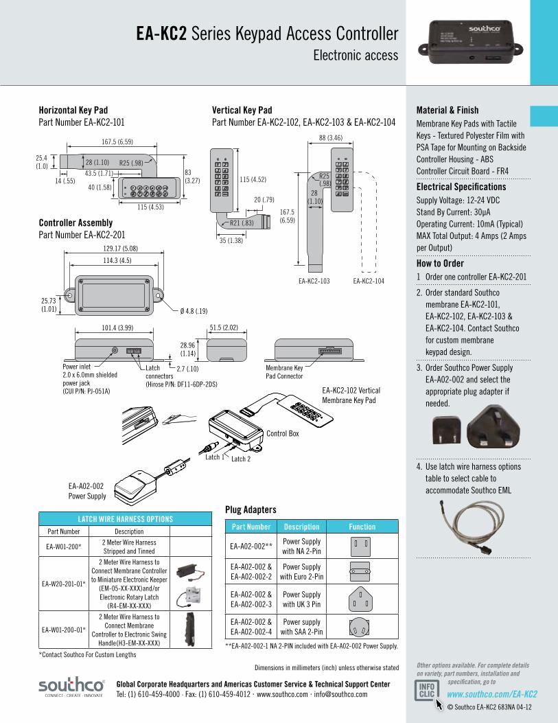
EA-KC2 Series Membrane Keypad Access ControllerElectronic access
The Membrane Keypad Access Controller simplifies access management with keyless entry in a self-contained unit. Designed to accommodate industrial equipment needs, the Membrane Keypad is easily customized and can be simply adhered to a door or frame. The remote controller can be mounted anywhere inside a cabinet and provides two outputs for independent control of two separate compartments. Flexible and easy to use, it can be customized to accommodate any look, shape or feel.
www.southco.com/EA-KC2© Southco EA-KC2 683NA 04-12
Dimensions in millimeters (inch) unless otherwise stated Other options available. For complete details on variety, part numbers, installation and specification, go to
129.17 (5.08)
114.3 (4.5)
101.4 (3.99)
Ø 4.8 (.19)
2.7 (.10)
28.96(1.14)
25.73 (1.01)
Membrane Key Pad Connector
Latchconnectors(Hirose P/N: DF11-6DP-2DS)
Power inlet2.0 x 6.0mm shieldedpower jack(CUI P/N: PJ-051A)
51.5 (2.02)
LATCH WIRE HARNESS OPTIONSPart Number Description
EA-W01-200*2 Meter Wire Harness Stripped and Tinned
EA-W20-201-01*
2 Meter Wire Harness to Connect Membrane Controller to Miniature Electronic Keeper
(EM-05-XX-XXX)and/or Electronic Rotary Latch
(R4-EM-XX-XXX)
EA-W01-200-01*
2 Meter Wire Harness to Connect Membrane
Controller to Electronic Swing Handle(H3-EM-XX-XXX)
Latch 2Latch 1
Material & FinishMembrane Key Pads with Tactile Keys - Textured Polyester Film with PSA Tape for Mounting on Backside Controller Housing - ABS Controller Circuit Board - FR4
Electrical SpecificationsSupply Voltage: 12-24 VDC Stand By Current: 30µA Operating Current: 10mA (Typical) MAX Total Output: 4 Amps (2 Amps per Output)
How to Order1 Order one controller EA-KC2-201
2. Order standard Southco membrane EA-KC2-101, EA-KC2-102, EA-KC2-103 & EA-KC2-104. Contact Southco for custom membrane keypad design.
3. Order Southco Power Supply EA-A02-002 and select the appropriate plug adapter if needed.
4. Use latch wire harness options table to select cable to accommodate Southco EML
EA-KC2 Series Keypad Access ControllerElectronic access
EA-A02-002 Power Supply
Controller Assembly Part Number EA-KC2-201
Horizontal Key Pad Part Number EA-KC2-101
EA-KC2-102 Vertical Membrane Key Pad
**EA-A02-002-1 NA 2-PIN included with EA-A02-002 Power Supply.*Contact Southco For Custom Lengths
Control Box
Global Corporate Headquarters and Americas Customer Service & Technical Support Center Tel: (1) 610-459-4000 · Fax: (1) 610-459-4012 · www.southco.com · [email protected]
Part Number Description Function
EA-A02-002**Power Supply with NA 2-Pin
EA-A02-002 & EA-A02-002-2
Power Supply with Euro 2-Pin
EA-A02-002 & EA-A02-002-3
Power Supply with UK 3 Pin
EA-A02-002 & EA-A02-002-4
Power supply with SAA 2-Pin
Plug Adapters
167.5 (6.59)
167.5(6.59)
115 (4.52)
20 (.79)
35 (1.38)
R21 (.83)
115 (4.53)
40 (1.58)
25.4(1.0) 28 (1.10)
14 (.55)43.5 (1.71)
R25 (.98)83(3.27)
28 (1.10)
88 (3.46)
EA-KC2-104EA-KC2-103
R25(.98)
Vertical Key Pad Part Number EA-KC2-102, EA-KC2-103 & EA-KC2-104
www.southco.com/EA-P1 Dimensions in millimeters (inch) unless otherwise stated
Other options available. For complete details on variety, part numbers, installation and specification, go to
1 2 3
4 5 6
7 8 9
0 #
Additional FeaturesLockout output provides alarm output after multiple failed access attempts, programmable from 1-99 attempts.
Tamper switch provides output if controller is removed from mounted surface.
Auxiliary input allows for additional remote input signal to open lock for programmed time.
• Simple card/PIN programming• LED indicator and audible feedback for programming and lock status• Up to 9,999 cards per controller • Non-volatile memory retains data after power is removed• Programmable door release time and alarm time• For use with EA-C1 series prox cards• Custom color and logo options
EA-P1 Series PIN/Prox Access ControllerElectronic access
Southco’s self-contained PIN/Prox controllers provide basic PIN/Prox access control with the flexibility to use PIN only, Prox only, or both PIN and Prox for added convenience and security. Simply supply 12 volt DC power and connect the output to any SOUTHCO® electromechanical latch for a complete electronic access solution. Enter a valid PIN or present a programmed prox card to the controller to produce an actuation signal.

ACTUAL SIZE
www.southco.com/EA-P1© Southco EA-P1 NA 09-09
JBJDJC118
(4.65)
75 (2.95)
Gasket
Bezel
Housing
18.9 (.75)Not including gasket
(gasket 1.7 (.067) uncompressed)
11.6 (.46)58 (2.28) 4 (.16)Thru 5 (.20)
Thru
8.3 (.33)
84.2(3.32)
109.5(4.31)
42.1 (1.66)
67.7 (2.66)
7 (.28)
2x Countersunk slots
JA (Blue)Door access
1 2 3 4 5 6 7 8 9 1 2 3 4
1 (Red)2 (Black) 3 (Brown)4 (Orange) 5 (Yellow)6 (Green)7 (Blue)8 (Purple)9 (Grey)
+12 VDCGround
Auxiliary inputXXX
NOCOMNC
Relay Output A(Max. 2A / 30 VDC)
Relay Output B(Max. 2A / 30 VDC)
E (Green)F (Blue)
Lockout alarm output (NO)Lockout alarm output (COM)
JB (White)Lockout alarm output
A B C D E F G H
J (Blue)K (Green) L (Yellow)
NCNOCOM
JC (Blue)Tamper switch output
J K L
1 (Red)2 (Yellow) 3 (Green)4 (Black)
+12VDCData1Data0Ground
JD (White)External Wiegand Reader
JA 1243
5
X X X X X
X X X
X
76(2.99)
Dimensions in millimeters (inch) unless otherwise stated Other options available. For complete details on variety, part numbers, installation and specification, go to
Material & FinishPolycarbonate and ABS Plastic
Electrical SpecificationsPIN Code Length: Programmable 1 to 8 digits
Monitoring Inputs: Auxiliary, case tampering
Typical Maximum Read Range: 10cm (depending on installation)
Frequency of Operation: 125kHz (EM), others available upon request
Modes of Operation: * Card-only * PIN or card * PIN and card * Bypass
Power: 12 VDC 80mA in standby, 105mA working current (typical)
Operating Temperature: 0-50 °C
Operating Humidity: 20-90% RH, no condensation
Connectors:Connector with approximately 160mm (6.3) of wiring, stripped and tinned provided with controller
1 JA Door access connector (blue 9-pin)
2 JB Lockout alarm connector (white 8-pin)
3 JC Tamper switch output connector (blue 3-pin)
4 JD Wiegand reader connector (white 4-pin)
5 Tamper switch
EA-P1 Series PIN/Prox Access ControllerElectronic access
EA - P1 - 01 C - L
Part Number Selection
Bezel Attached Without Bezel
Mounting
C Color 1 - White 2 - Cool Gray 0 - Black
L Omit - No Logo 9 - Southco Logo
Global Corporate Headquarters and Americas Customer Service & Technical Support CenterTel: (1) 610-459-4000 · Fax: (1) 610-459-4012 · www.southco.com · [email protected]
Connector Details(Note: Mating connectors with approximately 160mm (6.3) of wiring, stripped and tinned provided with controller).
Proximity card: EA - C1 - 011 (contact Southco for custom color and logo options)
EA-P1 Proximity ControllerOperating Instructions
J-EA-P1-01-M_revC visit www.southco.com for latest version of this document Page 1 of 4
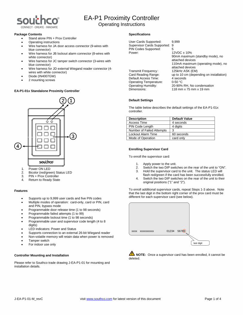
Package Contents Stand alone PIN + Prox Controller Operating instructions Wire harness for JA door access connector (9-wires with
blue connector) Wire harness for JB lockout alarm connector (8-wires with
white connector) Wire harness for JC tamper switch connector (3-wires with
blue connector) Wire harness for JD external Wiegand reader connector (4-
wires with white connector) Diode (IN4007GW) 2 mounting screws
EA-P1-01x Standalone Proximity Controller
12
3
4
12
3
4
1. Power ON LED2. Bicolor (red/green) Status LED3. PIN + Prox Controller4. Return to Ready State
Features
Supports up to 9,999 user cards and five PIN codes Multiple modes of operation: card-only, card or PIN, card
and PIN, bypass mode Programmable door release time (1 to 98 seconds) Programmable failed attempts (1 to 99) Programmable lockout time (1 to 98 seconds) Programmable user and supervisor code length (4 to 8
digits) LED indicators: Power and Status Supports connection to an external 26-bit Wiegand reader Non-volatile memory will retain data when power is removed Tamper switch For indoor use only
Controller Mounting and Installation
Please refer to Southco trade drawing J-EA-P1-01 for mounting andinstallation details.
Specifications
User Cards Supported: 9,999Supervisor Cards Supported: 9PIN Codes Supported: 5Power: 12VDC ± 10%
90mA maximum (standby mode), noattached devices110mA maximum (operating mode), noattached devices
Transmit Frequency: 125kHz ASK (EM)Card Reading Range: up to 10 cm (depending on installation)Default Access Time: 4 secondsOperating Temperature: 0-50 °COperating Humidity: 20-90% RH, No condensationDimensions: 118 mm x 75 mm x 19 mm
Default Settings
The table below describes the default settings of the EA-P1-01xcontroller.
Description Default ValueAccess Time 4 secondsPIN Code Length 4 digitsNumber of Failed Attempts 3Lockout Alarm Time 60 secondsMode of Operation card only
Enrolling Supervisor Card
To enroll the supervisor card:
1. Apply power to the unit.2. Switch the two DIP switches on the rear of the unit to “ON”.3. Hold the supervisor card to the unit. The status LED will
flash red/green if the card has been successfully enrolled.4. Switch the two DIP switches on the rear of the unit to their
original positions (“1” and “2”).
To enroll additional supervisor cards, repeat Steps 1-3 above. Notethat the last digit in the bottom right corner of the prox card must bedifferent for each supervisor card (see below).
NOTE: Once a supervisor card has been enrolled, it cannot bedeleted.
xxxx xxxxxxxxxx 01234 56789
last digit

EA-P1 Proximity ControllerOperating Instructions
J-EA-P1-01-M_revC visit www.southco.com for latest version of this document Page 2 of 4
Enrolling User Cards
User cards can be enrolled individually or in blocks. To enroll anindividual user card:
1. Hold the supervisor card to the unit.2. Enter 6-6-6-6 on the keypad.3. Enter the last four digits on the bottom right corner of the
prox card to be enrolled (example below).
4. To enroll another card, repeat Step #3 while the status LEDis still green.
5. The unit will return to user mode when the status LED turnsoff or if the ‘*’ (return-to-ready state) key is pressed.
To enroll a block of cards:
1. Hold the supervisor card to the unit.2. Enter 6-6-0-0 on the keypad.3. Enter the last four digits of the lowest card in the block to be
enrolled.4. Enter the last four digits of the highest card in the block to be
enrolled.5. The unit will return to user mode when the status LED turns
off or if the ‘*’ (return-to-ready state) key is pressed.
For example, entering 6-6-0-0 8-3-0-0 8-3-0-5 will enroll cards whoselast four digits range from 8300 to 8305.
Deleting User Cards
User cards can be deleted individually or in blocks. To delete anindividual user card:
1. Hold the supervisor card to the unit.2. Enter 7-7-7-7 on the keypad.3. Enter the last four digits on the bottom right corner of the
prox card to be deleted.4. To delete another card, repeat Step #3 while the status LED
is still green.5. The unit will return to user mode when the status LED turns
off or if the ‘*’ (return-to-ready state) key is pressed.
To delete a block of cards:
1. Hold the supervisor card to the unit.2. Enter 7-7-0-0 on the keypad.3. Enter the last four digits of the lowest numbered card in the
block to be deleted.4. Enter the last four digits of the highest numbered card in the
block to be deleted.5. The unit will return to user mode when the status LED turns
off or if the ‘*’ (return-to-ready state) key is pressed.
For example, entering 7-7-0-0 8-3-0-0 8-3-0-5 will delete cards whoselast four digits range from 8300 to 8305.
Enrolling and Changing PIN Numbers
Five PIN numbers can be enrolled. The default PIN number length isfour digits. To enroll a PIN number:
1. Hold the supervisor card to the unit.2. Enter 4-6-0-n on the keypad, where n is the slot number
(range 1-5).3. Enter the desired four digit PIN number.
Deleting PIN Numbers
PIN numbers may be deleted either individually or all at once. Todelete an individual PIN number:
1. Hold the supervisor card to the unit.2. Enter 4-7-0-n on the keypad, where n is the slot number
(range 1-5).
To delete all PIN numbers:
1. Hold the supervisor card to the unit.2. Enter 4-7-0-0 on the keypad.
Changing PIN Number Length
The default PIN number length is four digits. It can be programmed tobe four to eight digits. To change the PIN number length:
1. Hold the supervisor card to the unit.2. Enter 4-8-0-d, where d is the number of digits in the PIN
number (range 1-8).
NOTE: Changing the PIN code length will not deleteprogrammed PIN numbers. Changing the PIN code length to belonger than PIN numbers stored in memory will result in the PINs beingunusable. For example, if a four digit PIN is stored in memory, and thePIN number length is then changed to eight, then the PIN cannot beused.
However, if the PIN length is changed to be shorter than programmed
xxxx xxxxxxxxxx 01234 56789
last 4 digits
EA-P1 Proximity ControllerOperating Instructions
J-EA-P1-01-M_revC visit www.southco.com for latest version of this document Page 3 of 4
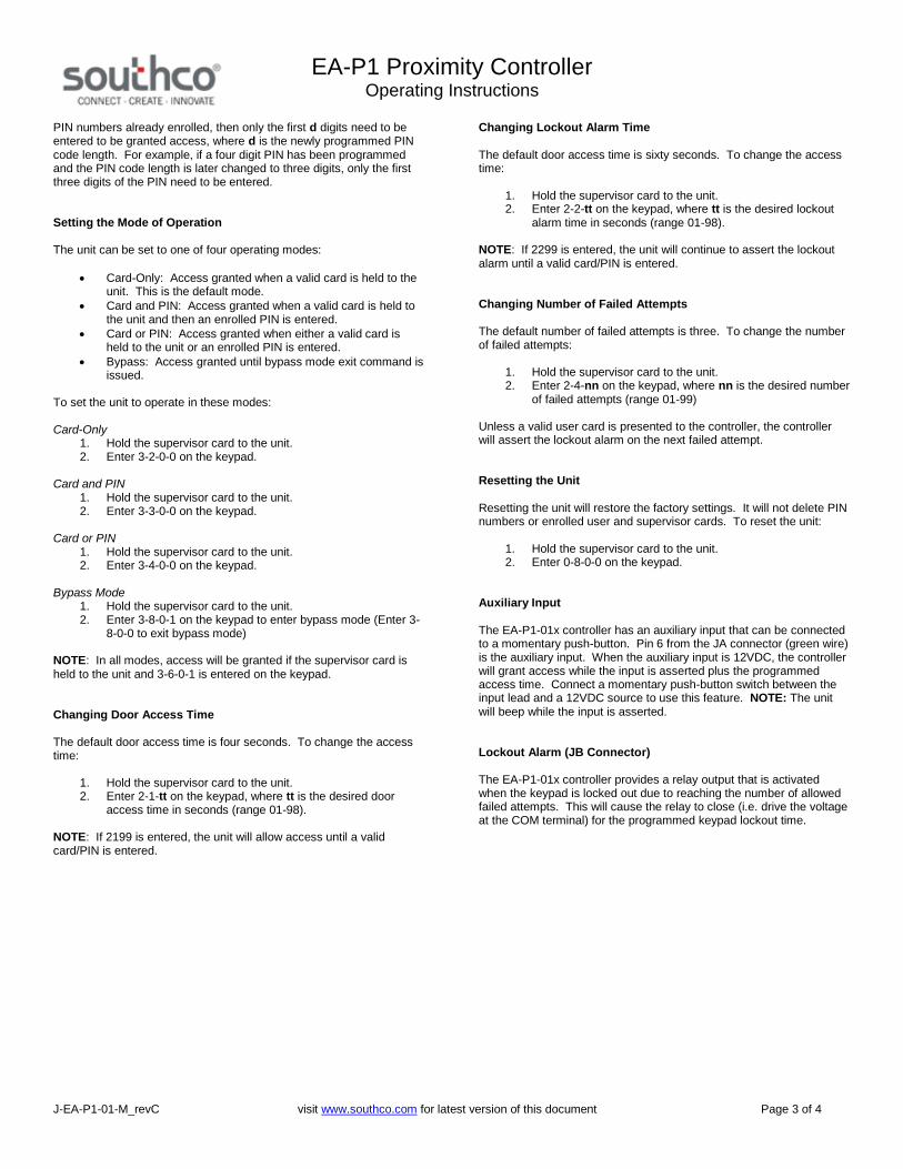
PIN numbers already enrolled, then only the first d digits need to beentered to be granted access, where d is the newly programmed PINcode length. For example, if a four digit PIN has been programmedand the PIN code length is later changed to three digits, only the firstthree digits of the PIN need to be entered.
Setting the Mode of Operation
The unit can be set to one of four operating modes:
Card-Only: Access granted when a valid card is held to theunit. This is the default mode.
Card and PIN: Access granted when a valid card is held tothe unit and then an enrolled PIN is entered.
Card or PIN: Access granted when either a valid card isheld to the unit or an enrolled PIN is entered.
Bypass: Access granted until bypass mode exit command isissued.
To set the unit to operate in these modes:
Card-Only1. Hold the supervisor card to the unit.2. Enter 3-2-0-0 on the keypad.
Card and PIN1. Hold the supervisor card to the unit.2. Enter 3-3-0-0 on the keypad.
Card or PIN1. Hold the supervisor card to the unit.2. Enter 3-4-0-0 on the keypad.
Bypass Mode1. Hold the supervisor card to the unit.2. Enter 3-8-0-1 on the keypad to enter bypass mode (Enter 3-
8-0-0 to exit bypass mode)
NOTE: In all modes, access will be granted if the supervisor card isheld to the unit and 3-6-0-1 is entered on the keypad.
Changing Door Access Time
The default door access time is four seconds. To change the accesstime:
1. Hold the supervisor card to the unit.2. Enter 2-1-tt on the keypad, where tt is the desired door
access time in seconds (range 01-98).
NOTE: If 2199 is entered, the unit will allow access until a validcard/PIN is entered.
Changing Lockout Alarm Time
The default door access time is sixty seconds. To change the accesstime:
1. Hold the supervisor card to the unit.2. Enter 2-2-tt on the keypad, where tt is the desired lockout
alarm time in seconds (range 01-98).
NOTE: If 2299 is entered, the unit will continue to assert the lockoutalarm until a valid card/PIN is entered.
Changing Number of Failed Attempts
The default number of failed attempts is three. To change the numberof failed attempts:
1. Hold the supervisor card to the unit.2. Enter 2-4-nn on the keypad, where nn is the desired number
of failed attempts (range 01-99)
Unless a valid user card is presented to the controller, the controllerwill assert the lockout alarm on the next failed attempt.
Resetting the Unit
Resetting the unit will restore the factory settings. It will not delete PINnumbers or enrolled user and supervisor cards. To reset the unit:
1. Hold the supervisor card to the unit.2. Enter 0-8-0-0 on the keypad.
Auxiliary Input
The EA-P1-01x controller has an auxiliary input that can be connectedto a momentary push-button. Pin 6 from the JA connector (green wire)is the auxiliary input. When the auxiliary input is 12VDC, the controllerwill grant access while the input is asserted plus the programmedaccess time. Connect a momentary push-button switch between theinput lead and a 12VDC source to use this feature. NOTE: The unitwill beep while the input is asserted.
Lockout Alarm (JB Connector)
The EA-P1-01x controller provides a relay output that is activatedwhen the keypad is locked out due to reaching the number of allowedfailed attempts. This will cause the relay to close (i.e. drive the voltageat the COM terminal) for the programmed keypad lockout time.
EA-P1 Proximity ControllerOperating Instructions
J-EA-P1-01-M_revC visit www.southco.com for latest version of this document Page 4 of 4
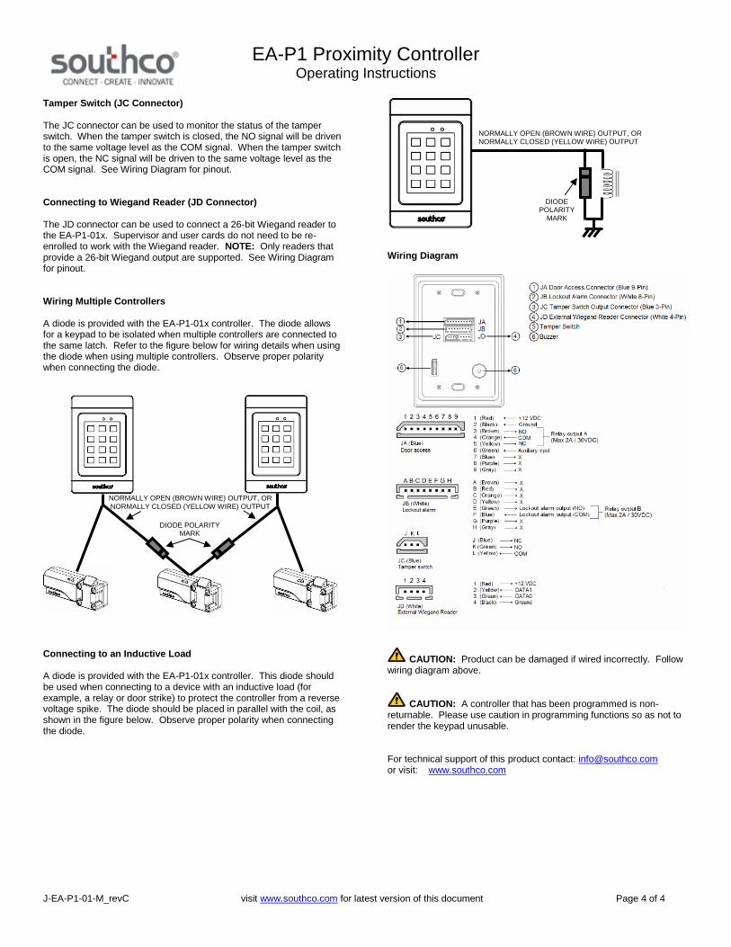
Tamper Switch (JC Connector)
The JC connector can be used to monitor the status of the tamperswitch. When the tamper switch is closed, the NO signal will be drivento the same voltage level as the COM signal. When the tamper switchis open, the NC signal will be driven to the same voltage level as theCOM signal. See Wiring Diagram for pinout.
Connecting to Wiegand Reader (JD Connector)
The JD connector can be used to connect a 26-bit Wiegand reader tothe EA-P1-01x. Supervisor and user cards do not need to be re-enrolled to work with the Wiegand reader. NOTE: Only readers thatprovide a 26-bit Wiegand output are supported. See Wiring Diagramfor pinout.
Wiring Multiple Controllers
A diode is provided with the EA-P1-01x controller. The diode allowsfor a keypad to be isolated when multiple controllers are connected tothe same latch. Refer to the figure below for wiring details when usingthe diode when using multiple controllers. Observe proper polaritywhen connecting the diode.
Connecting to an Inductive Load
A diode is provided with the EA-P1-01x controller. This diode shouldbe used when connecting to a device with an inductive load (forexample, a relay or door strike) to protect the controller from a reversevoltage spike. The diode should be placed in parallel with the coil, asshown in the figure below. Observe proper polarity when connectingthe diode.
Wiring Diagram
CAUTION: Product can be damaged if wired incorrectly. Followwiring diagram above.
CAUTION: A controller that has been programmed is non-returnable. Please use caution in programming functions so as not torender the keypad unusable.
For technical support of this product contact: [email protected] visit: www.southco.com
NORMALLY OPEN (BROWN WIRE) OUTPUT, ORNORMALLY CLOSED (YELLOW WIRE) OUTPUT
DIODE POLARITYMARK
NORMALLY OPEN (BROWN WIRE) OUTPUT, ORNORMALLY CLOSED (YELLOW WIRE) OUTPUT
DIODEPOLARITY
MARK
Dimensions in millimeters (inch) unless otherwise stated
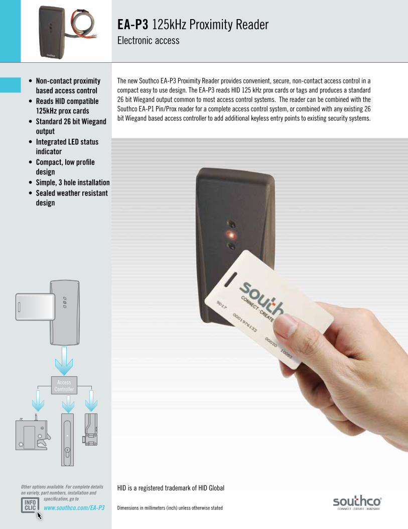
• Non-contactproximity basedaccesscontrol• ReadsHIDcompatible 125kHzproxcards• Standard26bitWiegand output• IntegratedLEDstatus indicator• Compact,lowprofile design• Simple,3holeinstallation• Sealedweatherresistant design
EA-P3125kHz Proximity Reader Electronic access
The new Southco EA-P3 Proximity Reader provides convenient, secure, non-contact access control in a compact easy to use design. The EA-P3 reads HID 125 kHz prox cards or tags and produces a standard 26 bit Wiegand output common to most access control systems. The reader can be combined with the Southco EA-P1 Pin/Prox reader for a complete access control system, or combined with any existing 26 bit Wiegand based access controller to add additional keyless entry points to existing security systems.
HID is a registered trademark of HID Global
www.southco.com/EA-P3
Other options available. For complete details on variety, part numbers, installation and specification, go to
Access Controller

© Southco NA MINI-EK 0510
11.28(.44)
Status LED
10.41(.41)
94 (3.7)
42.50 (1.67) 14.93 (.59)
3 (.12)
Ø 6.5(.26)
3 (.12)
M3 Clearance Hole
300mm (11.8’) Harness (stripped and tinned) installed
70.5(2.78)
Ø 10(.39) 31.95
(1.26)
6 (.24)
6 (.24)
31.95(1.26)
70.35(2.77)
11.28(.44)
Status LED
10.41(.41)
94 (3.7)
42.50 (1.67) 14.93 (.59)
3 (.12)
Ø 6.5(.26)
3 (.12)
M3 Clearance Hole
300mm (11.8’) Harness (stripped and tinned) installed
70.5(2.78)
Ø 10(.39) 31.95
(1.26)
6 (.24)
6 (.24)
31.95(1.26)
70.35(2.77)
Material&FinishABS Plastic
ElectricalSpecificationsSupply Voltage: 12VDC +/- 10%
Operating Current: 60 mA MAX (No Attached Devices)
Operating Temperature: -15 to 55 0C
Operating Humidity: 20-90% RH, No condensation
Transmit Frequency: 125kHz (FSK)
Read Range: Up to 10cm
26 Bit Wiegand Output
Reader will convert the user card ID to 26 bit Wiegand format
GlobalCorporateHeadquartersandAmericasCustomerService&TechnicalSupportCenter Concordville, PA – USA · Tel: (1) 610-459-4000 · Fax: (1) 610-459-4012
EA-P3125kHz Proximity ReaderElectronic access
WireHarnessLegend
Wire Color Function
Red VCC (12VDC)
Black GND
White Data 1
Green Data 0
Yellow GND
Brown No Function
Orange No Function
Blue No Function
PartNumberSelection
EA-P3-101-1 Proximity Reader (Gray Enclosure*)
EA-C2-021 Proximity Card (No Logo*)
www.southco.com/EA-P3© Southco EA-P3 NA 10-11
Dimensions in millimeters (inch) unless otherwise statedOther options available. For complete details on variety, part numbers, installation and specification, go to
PanelPreparation
* Contact Southco for Custom Color and Logo Options
www.southco.com/EA-R01 Dimensions in millimeters (inch) unless otherwise stated
Other options available. For complete details on variety, part numbers, installation and specification, go to
12VDCPOWERGND
AOUTPUT 1B
AOUTPUT 2B
AAUXGND
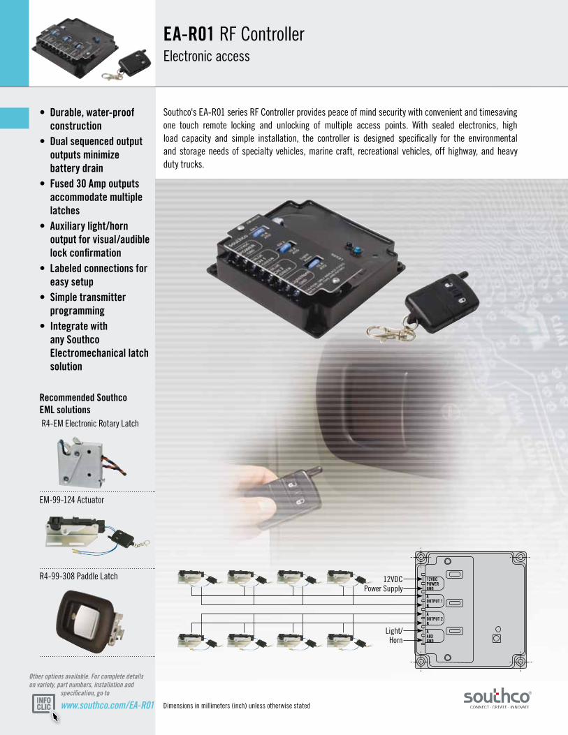
• Durable,water-proof construction• Dualsequencedoutput outputsminimize batterydrain• Fused30Ampoutputs accommodatemultiple latches• Auxiliarylight/horn outputforvisual/audible lockconfirmation• Labeledconnectionsfor easysetup• Simpletransmitter programming• Integratewith anySouthco Electromechanicallatch solution
EA-R01RFControllerElectronic access
Southco's EA-R01 series RF Controller provides peace of mind security with convenient and timesaving one touch remote locking and unlocking of multiple access points. With sealed electronics, high load capacity and simple installation, the controller is designed specifically for the environmental and storage needs of specialty vehicles, marine craft, recreational vehicles, off highway, and heavy duty trucks.
12VDC Power Supply
Light/ Horn
RecommendedSouthcoEMLsolutions R4-EM Electronic Rotary Latch
EM-99-124 Actuator
R4-99-308 Paddle Latch
Dimensions in millimeters (inch) unless otherwise stated
www.southco.com/EA-R01© Southco EA-R01 NA 02-10
Other options available. For complete details on variety, part numbers, installation and specification, go to
ScrewTerminal
GND
VCC
OUTPUT 1 A
OUTPUT 1 B
OUTPUT 2 A
OUTPUT 2 B
OUTPUT 3
GND
12VDCPOWERGND
AOUTPUT 1B
AOUTPUT 2B
AAUXGND
Fuses
127.0(5.00)
114.30(4.50)
Ø 4.95 (.195)
31.63(1.245) 22.23
(.875)
4.45(.175)
120.65 (4.750)
Nameplate/CoverLock button
Unlock button
Keyfob transmitter
Blue LED Nameplate screws
107.95 (4.250)
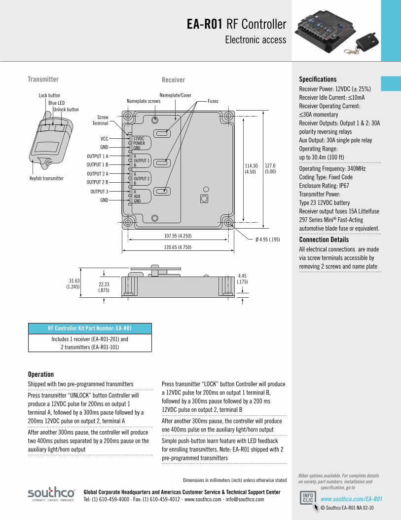
SpecificationsReceiver Power: 12VDC (± 25%) Receiver Idle Current: <10mA Receiver Operating Current: <30A momentaryReceiver Outputs: Output 1 & 2: 30A polarity reversing relays Aux Output: 30A single pole relay Operating Range: up to 30.4m (100 ft)
Operating Frequency: 340MHz Coding Type: Fixed Code Enclosure Rating: IP67 Transmitter Power: Type 23 12VDC battery Receiver output fuses 15A Littelfuse 297 Series Mini® Fast-Acting automotive blade fuse or equivalent.
ConnectionDetailsAll electrical connections are made via screw terminals accessible by removing 2 screws and name plate
OperationShipped with two pre-programmed transmitters
Press transmitter “UNLOCK” button Controller will produce a 12VDC pulse for 200ms on output 1 terminal A, followed by a 300ms pause followed by a 200ms 12VDC pulse on output 2, terminal A
After another 300ms pause, the controller will produce two 400ms pulses separated by a 200ms pause on the auxiliary light/horn output
Press transmitter “LOCK” button Controller will produce a 12VDC pulse for 200ms on output 1 terminal B, followed by a 300ms pause followed by a 200 ms 12VDC pulse on output 2, terminal B
After another 300ms pause, the controller will produce one 400ms pulse on the auxiliary light/horn output
Simple push-button learn feature with LED feedback for enrolling transmitters. Note: EA-R01 shipped with 2 pre-programmed transmitters
ReceiverTransmitter
EA-R01RFControllerElectronic access
RFControllerKitPartNumber:EA-R01
Includes 1 receiver (EA-R01-201) and2 transmitters (EA-R01-101)
GlobalCorporateHeadquartersandAmericasCustomerService&TechnicalSupportCenterTel: (1) 610-459-4000 · Fax: (1) 610-459-4012 · www.southco.com · [email protected]
Dimensions in millimeters (inch) unless otherwise stated
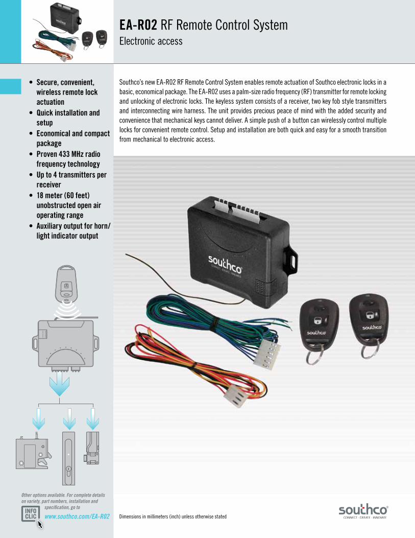
• Secure,convenient, wirelessremotelock actuation• Quickinstallationand setup• Economicalandcompact package• Proven433MHzradio frequencytechnology• Upto4transmittersper receiver• 18meter(60feet) unobstructedopenair operatingrange• Auxiliaryoutputforhorn/ lightindicatoroutput
EA-R02RF Remote Control System Electronic access
Southco’s new EA-R02 RF Remote Control System enables remote actuation of Southco electronic locks in a basic, economical package. The EA-R02 uses a palm-size radio frequency (RF) transmitter for remote locking and unlocking of electronic locks. The keyless system consists of a receiver, two key fob style transmitters and interconnecting wire harness. The unit provides precious peace of mind with the added security and convenience that mechanical keys cannot deliver. A simple push of a button can wirelessly control multiple locks for convenient remote control. Setup and installation are both quick and easy for a smooth transition from mechanical to electronic access.
www.southco.com/EA-R02
Other options available. For complete details on variety, part numbers, installation and specification, go to
© Southco NA MINI-EK 0510
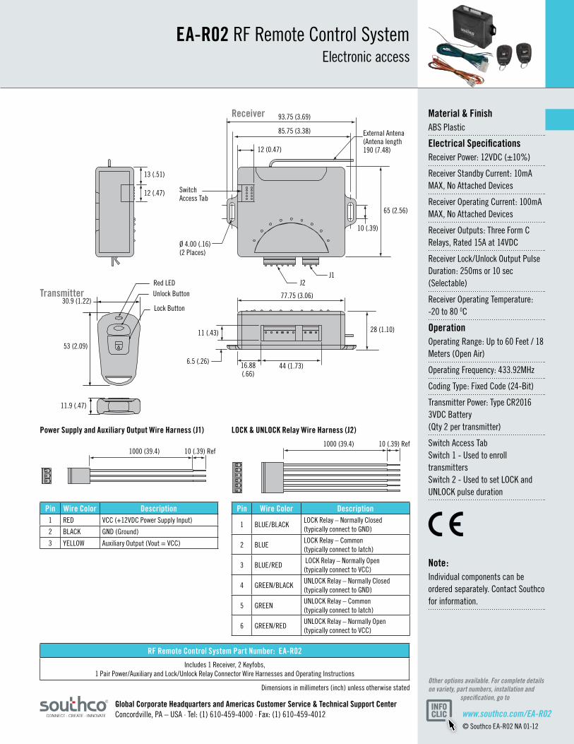
93.75 (3.69)
85.75 (3.38)
65 (2.56)
28 (1.10)
77.75 (3.06)
11 (.43)
6.5 (.26) 16.88(.66)
44 (1.73)
J1J2
Ø 4.00 (.16)(2 Places)
Switch Access Tab
Red LEDUnlock Button
Lock Button30.9 (1.22)
53 (2.09)
11.9 (.47)
12 (.47)
13 (.51)
10 (.39)
12 (0.47)
External Antena(Antena length 190 (7.48)
Pin WireColor Description1 RED VCC (+12VDC Power Supply Input)
2 BLACK GND (Ground)
3 YELLOW Auxiliary Output (Vout = VCC)
Pin WireColor Description
1 BLUE/BLACKLOCK Relay – Normally Closed (typically connect to GND)
2 BLUELOCK Relay – Common (typically connect to latch)
3 BLUE/RED LOCK Relay – Normally Open (typically connect to VCC)
4 GREEN/BLACKUNLOCK Relay – Normally Closed (typically connect to GND)
5 GREENUNLOCK Relay – Common (typically connect to latch)
6 GREEN/REDUNLOCK Relay – Normally Open (typically connect to VCC)
PowerSupplyandAuxiliaryOutputWireHarness(J1) LOCK&UNLOCKRelayWireHarness(J2)
Receiver
Transmitter
10 (.39) Ref1000 (39.4)10 (.39) Ref1000 (39.4)
10 (.39) Ref1000 (39.4)10 (.39) Ref1000 (39.4)
Material&FinishABS Plastic
ElectricalSpecificationsReceiver Power: 12VDC (±10%)
Receiver Standby Current: 10mA MAX, No Attached Devices
Receiver Operating Current: 100mA MAX, No Attached Devices
Receiver Outputs: Three Form C Relays, Rated 15A at 14VDC
Receiver Lock/Unlock Output Pulse Duration: 250ms or 10 sec (Selectable)
Receiver Operating Temperature: -20 to 80 0C
OperationOperating Range: Up to 60 Feet / 18 Meters (Open Air)
Operating Frequency: 433.92MHz
Coding Type: Fixed Code (24-Bit)
Transmitter Power: Type CR2016 3VDC Battery (Qty 2 per transmitter)
Switch Access Tab Switch 1 - Used to enroll transmitters Switch 2 - Used to set LOCK and UNLOCK pulse duration
Note:Individual components can be ordered separately. Contact Southco for information.
GlobalCorporateHeadquartersandAmericasCustomerService&TechnicalSupportCenter Concordville, PA – USA · Tel: (1) 610-459-4000 · Fax: (1) 610-459-4012
RFRemoteControlSystemPartNumber:EA-R02
Includes 1 Receiver, 2 Keyfobs, 1 Pair Power/Auxiliary and Lock/Unlock Relay Connector Wire Harnesses and Operating Instructions
www.southco.com/EA-R02© Southco EA-R02 NA 01-12
Dimensions in millimeters (inch) unless otherwise statedOther options available. For complete details on variety, part numbers, installation and specification, go to
EA-R02RF Remote Control System Electronic access
26
별도의 언급이 없는 한 규격들은 밀리미터 로 표시합니다www.southco.com/EM
EM 전자 키퍼전자 스트라이크
어떠한 수동 래칭
시스템이라도 고정된
키퍼 부품을 전자식
조작 기능을 갖춘 전자
키퍼로 교체하기만 하면
업그레이드가 가능합니다.
다목적 전자키퍼는 다양한
탑재 구성과 간단한
설치 및 조작 기능을
갖추고 있어 다양한
어플리케이션에 적용
가능합니다.
• 기계식에서 전자 엑세
스로 간단하게 바꾸
실 수 있습니다.
• "밀어닫기" 어떠한 어
플리케이션이나 개선
또는 신규 설치에도
편리합니다.
• 어떠한 전자 기기의
신호도 수용 할 수 있
습니다.
• 프레임에 장착되어 배
선이 간편합니다.
• 싱글 또는 멀티 포인
트 래칭 선택 가능합
니다.
• 원격 모니터링, 추적
감사 및 경보 기능이
있습니다.
• 기계식 래치가 장착된
다양한 도어와 호환
가능합니다.
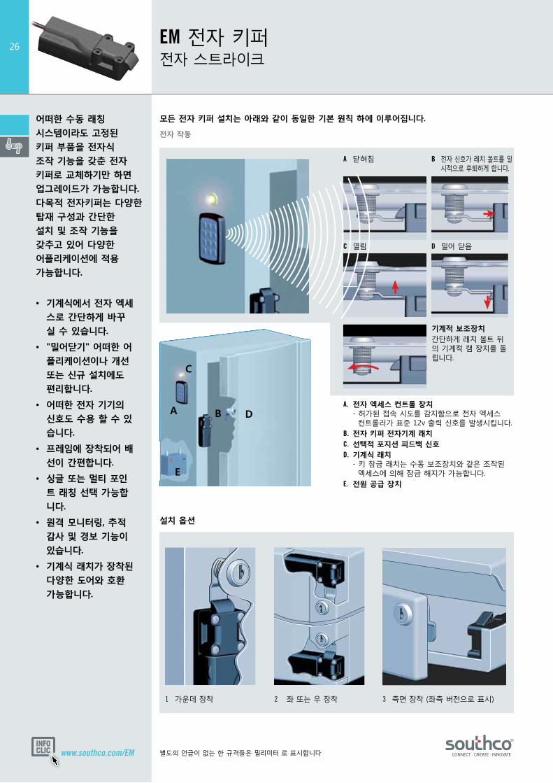
A. 전자 엑세스 컨트롤 장치 - 허가된 접속 시도를 감지함으로 전자 엑세스 컨트롤러가 표준 12v 출력 신호를 발생시킵니다.B. 전자 키퍼 전자기계 래치C. 선택적 포지션 피드백 신호D. 기계식 래치 - 키 잠금 래치는 수동 보조장치와 같은 조작된 엑세스에 의해 잠금 해지가 가능합니다.E. 전원 공급 장치
A 닫혀짐 B 전자 신호가 래치 볼트를 일 시적으로 후퇴하게 합니다.
C 열림 D 밀어 닫음
모든 전자 키퍼 설치는 아래와 같이 동일한 기본 원칙 하에 이루어집니다.
1 가운데 장착 2 좌 또는 우 장착 3 측면 장착 (좌측 버전으로 표시)
전자 작동
설치 옵션
E
D
C
A B
기계적 보조장치 간단하게 래치 볼트 뒤의 기계적 캠 장치를 돌립니다.
27
별도의 언급이 없는 한 규격들은 밀리미터 로 표시합니다 www.southco.com/EM
8.25
래치 볼트
24 34
5
524
92
2.918.2
Ø 4.25 카운터싱크를관통 Ø 7.4 x 1.65 4 x
Ø 4.25 카운터싱크를관통 Ø 7.4 x 1.65 4 x
24.25 25
커넥터 세부 내역
핀 3핀 1
핀 2 핀 4
10.2
12
8.25
24 34
5
524
92
18.2
래치 볼트2.9
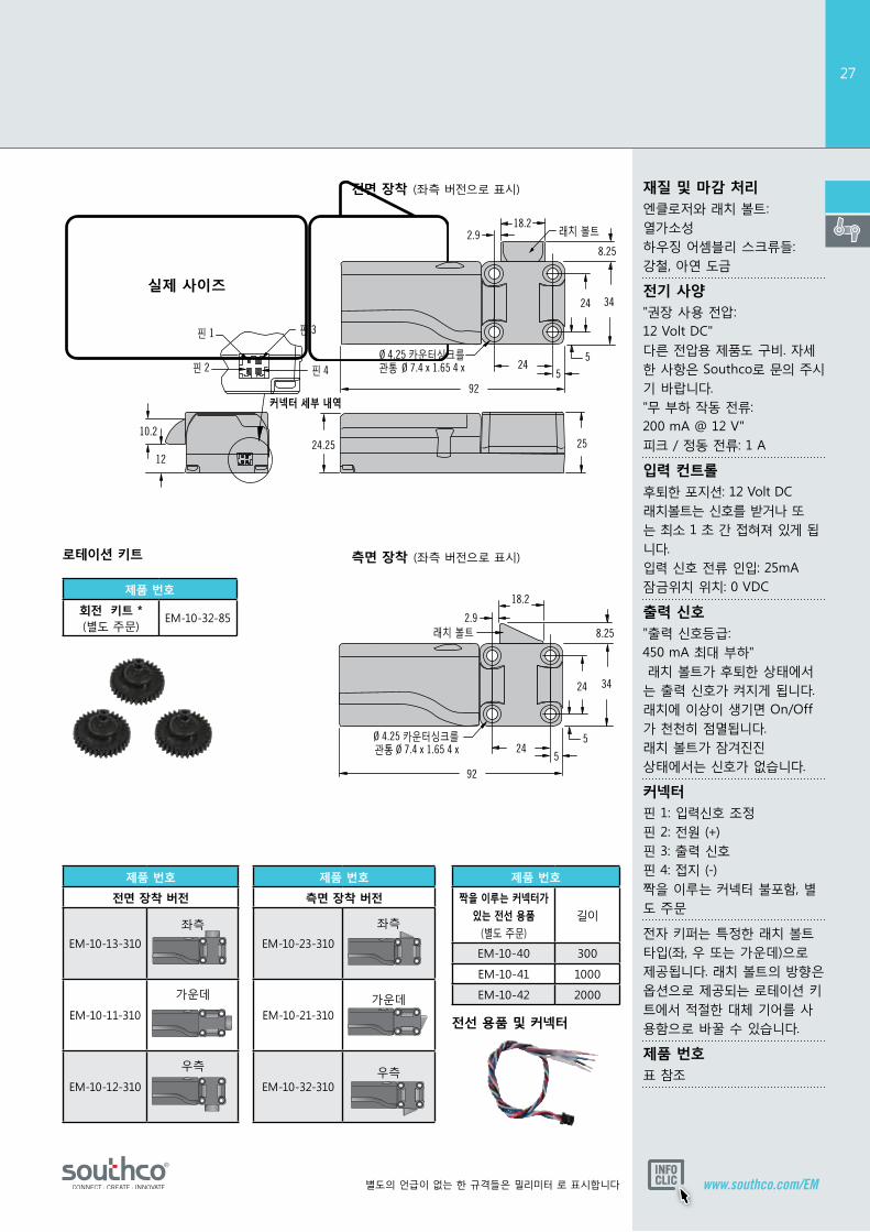
재질 및 마감 처리엔클로저와 래치 볼트: 열가소성 하우징 어셈블리 스크류들: 강철, 아연 도금
전기 사양"권장 사용 전압: 12 Volt DC" 다른 전압용 제품도 구비. 자세한 사항은 Southco로 문의 주시기 바랍니다. "무 부하 작동 전류: 200 mA @ 12 V" 피크 / 정동 전류: 1 A
입력 컨트롤후퇴한 포지션: 12 Volt DC 래치볼트는 신호를 받거나 또는 최소 1 초 간 접혀져 있게 됩니다. 입력 신호 전류 인입: 25mA 잠금위치 위치: 0 VDC
출력 신호"출력 신호등급: 450 mA 최대 부하" 래치 볼트가 후퇴한 상태에서는 출력 신호가 켜지게 됩니다. 래치에 이상이 생기면 On/Off가 천천히 점멸됩니다. 래치 볼트가 잠겨진진 상태에서는 신호가 없습니다.
커넥터핀 1: 입력신호 조정 핀 2: 전원 (+) 핀 3: 출력 신호 핀 4: 접지 (-) 짝을 이루는 커넥터 불포함, 별도 주문
전자 키퍼는 특정한 래치 볼트 타입(좌, 우 또는 가운데)으로 제공됩니다. 래치 볼트의 방향은 옵션으로 제공되는 로테이션 키트에서 적절한 대체 기어를 사용함으로 바꿀 수 있습니다.
제품 번호표 참조
전면 장착 (좌측 버전으로 표시)
측면 장착 (좌측 버전으로 표시)
전선 용품 및 커넥터
로테이션 키트
제품 번호
전면 장착 버전
EM-10-13-310
좌측
EM-10-11-310
가운데
EM-10-12-310
우측
제품 번호
회전 키트 * (별도 주문)
EM-10-32-85
제품 번호
짝을 이루는 커넥터가
있는 전선 용품
(별도 주문)
길이
EM-10-40 300
EM-10-41 1000
EM-10-42 2000
제품 번호
측면 장착 버전
EM-10-23-310
좌측
EM-10-21-310가운데
EM-10-32-310우측

Dimensions in millimeters (inch) unless otherwise stated
• Simpletransitionfrom mechanicaltoelectronic access• “Push-to-close” convenienceforany application–retrofitor newinstallation• Frontmountandside mountversions• Concealedlatching• Microprocessor controlledgearmotor• Minimalpowerdraw• Simplemechanical override• Optionalinternal microswitchforlatch open/closeoutputsignal• Wideoperatingvoltage range(8-26VDC)• Acceptssignalsfromany electronicactuation source• Singleormulti-point latching• Workswithavarietyof doormounted mechanicallatches
EM-05Miniature Electronic Keeper Electronic access
The EM-05 Miniature Electronic Keeper provides a simple, versatile electromechanical latch solution for a variety of applications. Add a 12-24 Volt DC power supply and any access control device to the EM-05 for a secure, concealed electronic access solution. The optional internal microswitch provides an output signal to remotely monitor latch status or control external systems.
Front mount configuration for low profile applications.
Alternate latch bolt configuration for side mount applications.
Convenient mechanical override feature for manual release in case of power failure. Contact Southco for manual release cables.
www.southco.com/EM-05
Other options available. For complete details on variety, part numbers, installation and specification, go to
DOOROPEN
1 2 3
4 5 6
7 8 9
* 0 #

Ø 4.3 (0.17) thru
17.5(0.69)
17.5(0.69)
37.5(1.48)
15.5 (0.61)2.75 (0.11)
2.75 (0.11)
27(1.06)
7.76 (0.31) 7mm (0.27) travel 7.76 (0.31) 7mm (0.27) travel
10 (0.4)
10 (0.4)
5 (0.2)5.25 (0.21)
13.5 (0.53)13.5 (0.53)12 (0.47)
5 (0.2)5.25(0.21)
271.06)
12 (0.47)Mechanical Override Ball End Cable Connector(Will accept ø1.6 ± 0.15 (0.063 ± 0.006) cable with ø4.78 ± 0.13 (0.188 ± 0.005) ball)
73.5 (2.89)
145 REF (5.71)
Max Travel 8mm (.315)
8.6(0.73)
7.25 (0.29)
FrontMountMiniE-Keeper(Front version shown)
© Southco NA MINI-EK 0510
1 1 2
3PIN 3PIN 2PIN 1
PIN 1 Indicator
PIN 6PIN 5PIN 4
Material&FinishEnclosure & Latch Bolt: Thermoplastic Housing Assembly Screws: Steel, Zinc Plate
ElectricalSpecificationsRecommended Operating Voltage: 12 - 24 VDC
Typical Operating Current: Less than 600mA at 12 VDC
ControlInputRetracted Position: 12-24 VDC The latch bolt will remain retracted for as long as the signal is present or a minimum of 1 second. Input Signal Current: 25mA Max at 24 VDC
Extended Position: 0 VDC
WireColorCode/ConnectorPinAssignment:PIN 1 Brown: Ground (-) PIN 2 Red: Power 8 to 26 VDC PIN 3 Orange: Control Signal 8 to 26 VDC PIN 4 Black: Microswitch Common PIN 5 Blue: Microswitch N.O. Contact PIN 6: None
GlobalCorporateHeadquartersandAmericasCustomerService&TechnicalSupportCenterConcordville, PA – USA · Tel: (1) 610-459-4000 · Fax: (1) 610-459-4012
* For Mechanical Version of Front Mount Style order part number EM-05-11-001 * For Mechanical Version of Side Mount Style order part number EM-05-21-001 (Mechanical version does not include drive motor or electronics)
EM-05Miniature Electronic Keeper Electronic access
MINIATUREELECTRONICKEEPERPARTNUMBERS
TypeWith Mechanical Override Without Mechanical Override
With Switch Without Switch With Switch Without Switch
Front Mount Latch Bolt EM-05-11-111 EM-05-11-101* EM-05-11-110 EM-05-11-100
Side Mount Latch Bolt EM-05-21-111 EM-05-21-101* EM-05-21-110 EM-05-21-100
www.southco.com/EM-05© Southco EM-05 NA 11-10
Dimensions in millimeters (inch) unless otherwise statedOther options available. For complete details on variety, part numbers, installation and specification, go to
LatchConnectorMolex Microfit 3.0 series
SideMount FrontMount