Embed Size (px)
Citation preview
© IECA (Australasia) June 2018 Page 1
Sediment Basins SEDIMENT CONTROL TECHNIQUE
Type 1 System Sheet Flow Sandy Soils Type 2 System Concentrated Flow Clayey Soils
Type 3 System Instream Works Dispersive Soils
Symbol
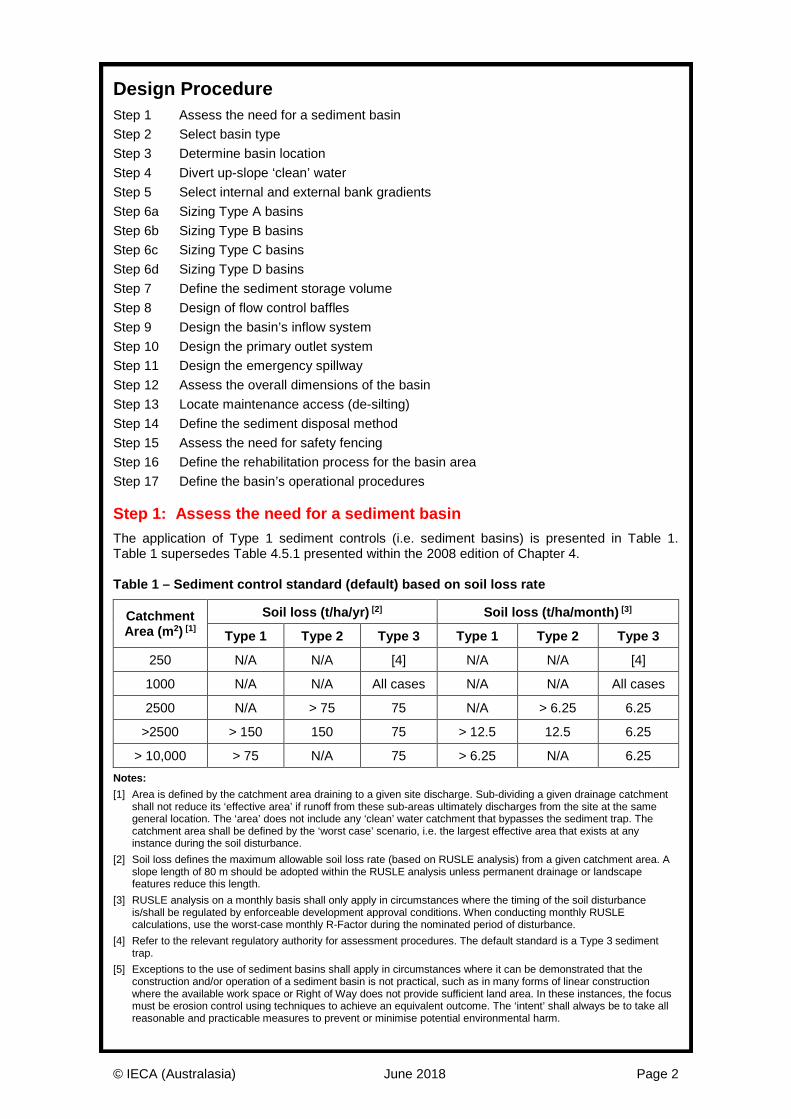
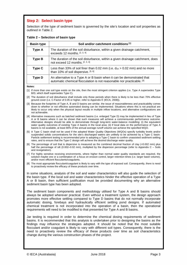
Photo 1 – Type A basin Photo 2 – Type C basin
Key Principles 1. Sediment trapping is primarily achieved through particle settlement. Some basins may
incorporate a filtration system within the outlet structure, but these filters are generally unreliable. Consequently the focus should always remain on achieving effective particle settlement.
2. Achieving optimum particle settlement relies upon achieving uniform flow conditions across the settling pond, and if chemical dosing is required, selecting the most appropriate flocculant and/or coagulant, and then achieving effective ‘mixing’ prior to the treated flows entering the settling pond.
3. The size of the settling pond is directly related to the ‘volume’ of runoff and/or peak design ‘discharge’. Pond volume is critical for basins operate as plug flow systems; while the pond surface area is critical for sediment basins that operate as continuous flow systems. Both pond volume and surface area are critical for Type A basins.
4. It should be noted that even if a basin is full of water, it can still be effective in removing coarse sediments from inflows. Therefore, unlike permanent stormwater treatment ponds, flows in excess of the design storm should still be directed through the sediment basin.
Design Information A sediment basin is a purpose built dam designed to collect and settle sediment-laden water. It usually consists of an inlet chamber (forebay), a primary settling pond, a decant system, and a high-flow emergency spillway. This fact sheet summaries the design requirements for four types of sediment basins, Type A, Type B, Type C and Type D basins. Detailed discussion on the design procedures is provided in Book 2’s Appendix B (June, 2018).
© IECA (Australasia) June 2018 Page 2
Design Procedure Step 1 Assess the need for a sediment basin Step 2 Select basin type Step 3 Determine basin location Step 4 Divert up-slope ‘clean’ water Step 5 Select internal and external bank gradients Step 6a Sizing Type A basins Step 6b Sizing Type B basins Step 6c Sizing Type C basins Step 6d Sizing Type D basins Step 7 Define the sediment storage volume Step 8 Design of flow control baffles Step 9 Design the basin’s inflow system Step 10 Design the primary outlet system Step 11 Design the emergency spillway Step 12 Assess the overall dimensions of the basin Step 13 Locate maintenance access (de-silting) Step 14 Define the sediment disposal method Step 15 Assess the need for safety fencing Step 16 Define the rehabilitation process for the basin area Step 17 Define the basin’s operational procedures Step 1: Assess the need for a sediment basin The application of Type 1 sediment controls (i.e. sediment basins) is presented in Table 1. Table 1 supersedes Table 4.5.1 presented within the 2008 edition of Chapter 4. Table 1 – Sediment control standard (default) based on soil loss rate
Catchment Area (m2) [1]
Soil loss (t/ha/yr) [2] Soil loss (t/ha/month) [3]
Type 1 Type 2 Type 3 Type 1 Type 2 Type 3
250 N/A N/A [4] N/A N/A [4]
1000 N/A N/A All cases N/A N/A All cases
2500 N/A > 75 75 N/A > 6.25 6.25
>2500 > 150 150 75 > 12.5 12.5 6.25
> 10,000 > 75 N/A 75 > 6.25 N/A 6.25 Notes: [1] Area is defined by the catchment area draining to a given site discharge. Sub-dividing a given drainage catchment
shall not reduce its ‘effective area’ if runoff from these sub-areas ultimately discharges from the site at the same general location. The ‘area’ does not include any ‘clean’ water catchment that bypasses the sediment trap. The catchment area shall be defined by the ‘worst case’ scenario, i.e. the largest effective area that exists at any instance during the soil disturbance.
[2] Soil loss defines the maximum allowable soil loss rate (based on RUSLE analysis) from a given catchment area. A slope length of 80 m should be adopted within the RUSLE analysis unless permanent drainage or landscape features reduce this length.
[3] RUSLE analysis on a monthly basis shall only apply in circumstances where the timing of the soil disturbance is/shall be regulated by enforceable development approval conditions. When conducting monthly RUSLE calculations, use the worst-case monthly R-Factor during the nominated period of disturbance.
[4] Refer to the relevant regulatory authority for assessment procedures. The default standard is a Type 3 sediment trap.
[5] Exceptions to the use of sediment basins shall apply in circumstances where it can be demonstrated that the construction and/or operation of a sediment basin is not practical, such as in many forms of linear construction where the available work space or Right of Way does not provide sufficient land area. In these instances, the focus must be erosion control using techniques to achieve an equivalent outcome. The ‘intent’ shall always be to take all reasonable and practicable measures to prevent or minimise potential environmental harm.
© IECA (Australasia) June 2018 Page 3
Step 2: Select basin type Selection of the type of sediment basin is governed by the site’s location and soil properties as outlined in Table 2. Table 2 – Selection of basin type
Basin type Soil and/or catchment conditions [1]
Type A The duration of the soil disturbance, within a given drainage catchment, exceeds 12 months. [2, 3, 4]
Type B The duration of the soil disturbance, within a given drainage catchment, does not exceed 12 months. [2, 3, 4]
Type C Less than 33% of soil finer than 0.02 mm (i.e. d33 > 0.02 mm) and no more than 10% of soil dispersive. [5, 6]
Type D An alternative to a Type A or B basin when it can be demonstrated that automatic chemical flocculation is not reasonable nor practicable. [3]
Notes: [1] If more than one soil type exists on the site, then the most stringent criterion applies (i.e. Type A supersedes Type
B/D, which itself supersedes Type C). [2] The duration of soil disturbance shall include only those periods when there is likely to be less than 70% effective
ground cover (i.e. C-Factor of 0.05 or higher, refer to Appendix E (IECA, 2008)). [3] Because the footprints of Type A, B and D basins are similar, the issue of reasonableness and practicability comes
down to whether or not effective automated dosing can be implemented. Situations where this is not practical are likely to occur only when the physical layout results in multiple inflow locations, and alternative configurations are not achievable.
[4] Alternative measures such as batched sediment basins (i.e. enlarged Type D) may be implemented in lieu of Type A or B basins where it can be shown that such measures will achieve a commensurate performance outcome. Alternative designs should be able to demonstrate through long-term water-balance modelling: (i) the equivalent water quality outcomes of existing Type A basins in the local area; (ii) if local data on the performance of Type A basins is not available, at least 80% of the annual average runoff volume can achieve the specified WQO.
[5] A Type C basin shall not be used if the adopted Water Quality Objectives (WQOs) specify turbidity levels and/or suspended solids concentrations for the site’s discharged waters are unlikely to be achieved by a Type C basin. Particle settlement testing is recommended prior to adopting a Type C basin to confirm unassisted sediment settling rates, and to ensure that the Type C design will achieve the desired discharge water quality.
[6] The percentage of soil that is dispersive is measured as the combined decimal fraction of clay (<0.002 mm) plus half the percentage of silt (0.002–0.02 mm), multiplied by the dispersion percentage (refer to Appendix C – Soils and revegetation).
[7] For highly sensitive receiving environments, where higher than normal water quality standards are required, the solution maybe one or a combination of: a focus on erosion control, larger retention times (i.e. larger basin volume), and/or more efficient flocculants/coagulants.
[8] The most appropriate flocculant/coagulant is likely to vary with the type of exposed soil. Consequently, there is need to proactively review the efficacy of these products over time.
In some situations, analysis of the soil and water characteristics will also guide the selection of the basin type. If the local soil and water characteristics hinder the effective operation of a Type A or B basin, then sufficient justification must be provided documenting why an alternative sediment basin type has been adopted. The sediment basin components and methodology utilised for Type A and B basins should always be adopted wherever practical. Even without a treatment system, the design approach promotes more effective settling compared to Type D basins that do not normally incorporate automatic dosing, forebays and hydraulically efficient settling pond designs. If automated chemical treatment is not incorporated into the operation of a basin, then the operational requirements will need to be modified to that presented for Type A and B basins. Jar testing is required in order to determine the chemical dosing requirements of sediment basins. It is recommended that this analysis is undertaken prior to designing the basins as the findings may influence the strategies adopted. It should be noted that the most suitable flocculant and/or coagulant is likely to vary with different soil types. Consequently, there is the need to proactively review the efficacy of these products over time as soil characteristics change during the various construction phases of the project.

© IECA (Australasia) June 2018 Page 4
Step 3: Determine basin location All reasonable and practicable measures must be taken to locate sediment basins within the work site in a manner that maximises the basin’s overall sediment trapping efficiency. Issues that need to be given appropriate consideration include:
(i) Locate all basins within the relevant property boundary, unless the permission of the adjacent land-holder has been provided.
(ii) Locate all basins to maximise the collection of sediment-laden runoff generated from within the site throughout the construction period, which extends up until the site is adequately stabilised against soil erosion, including raindrop impact.
(iii) Do not locate a sediment basin within a waterway, or major drainage channel, unless it can be demonstrated that: • the basin will be able to achieve its design requirements, i.e. the specified
treatment standard (water quality objective); • settled sediment will not be resuspended and washed from the basin during
stream flows equal to, or less than, the 1 in 5 year ARI (18% AEP); • the basin and emergency spillway will be structurally sound during the design
storm specified for the sizing of the emergency spillway.
(iv) Where practical, locate sediment basins above the 1 in 5 year ARI (18% AEP) flood level. Where this is not practical, then all reasonable efforts must be taken to maximise the flood immunity of the basin.
(v) Avoid locating a basin in an area where adjacent construction works may limit the operational life of the basin.
(vi) Assess and minimise secondary impacts such as disturbance to tree roots, particularly of significant individual trees. These impacts may extend to trees on adjacent lands (refer to AS4970 - Protection of trees on development sites).
(vii) Ensure basins have suitable access for maintenance and de-silting. If the excavated basin is to be retained as a permanent land feature following the construction period—for example as a stormwater detention/retention system—then the location of the basin may in part be governed by the requirements of this final land feature. However, if the desired location of this permanent land feature means that the basin will be ineffective in the collection and treatment of sediment-laden runoff, then an alternative basin location will be required. Discussion: It should be remembered that it is not always necessary to restrict the site to the use of just one sediment basin. In some locations it may be highly desirable to divide the work site into smaller, more manageable sub-catchments, and to place a separate basin within each sub-catchment.
It is generally undesirable to divide a basin into a series of two or more in-line basins. Several small basins operating in series can have significantly less sediment trapping efficiency than a single basin. This is because of the remixing that occurs when flow from one basin spills into, or is piped into, the subsequent basin. There are exceptions to this rule, such as:
• Type A basins where the combined basin volume satisfies the minimum volume requirement, and at least one of the basins is able to, on its own, satisfy the minimum surface area requirement.
• Type D basins where at least one of the basins has sufficient surface area and length to width ratio to satisfy the requirements of a Type C basin. The combined settling volume of the basins must not be less than that specified for a Type D basin.
• A series of Type C or D basins where each settling pond is connected by several pipes or culverts evenly spaced across the full width of the basin. Such a design must minimise the effects of inflow jetting from each pipe/culvert and allow an even distribution of flow across the full basin width. In such cases the minor sediment remixing that occurs as flow passes through the interconnecting pipes/culverts is usually compensated for by the improved hydraulic efficiency of the overall basin surface area.
© IECA (Australasia) June 2018 Page 5
Step 4: Divert up-slope ‘clean’ water Wherever reasonable and practicable, up-slope ‘clean’ water should be diverted around the sediment basin to decrease the size and cost of the basin, and increase its efficiency. If flow diversion systems are used to divert clean water around the basin, then these systems will usually need to be modified as new areas of land are first disturbed, then stabilised. ‘Clean’ water is defined as water that has not been contaminated within the property, or by activities directly associated with the construction/building works. The intent is to minimise the volume of uncontaminated water flowing to a basin at any given time during the operation of the basin. Discussion: One of the primary goals of an effective erosion and sediment control program is to divert external run-on water and any uncontaminated site water around major sediment control devices such as sediment basins.
The effective catchment area may vary significantly during the construction phase as areas of disturbance are first connected to a sediment basin, then taken off-line as site rehabilitation occurs. It is considered best practice to prepare a Construction Drainage Plan (CDP) for each stage of earth works. Step 5: Select internal and external bank gradients It is usually necessary to determine the internal bank gradients of sediment basins before sizing the basin because this bank gradient can alter the mathematical relationship between pond surface area and volume. Recommended bank gradients are provided in Table 3. Table 3 – Suggested bank slopes
Slope (V:H) Bank/soil description
1:2 Good, erosion-resistant clay or clay-loam soils
1:3 Sandy-loam soil
1:4 Sandy soils
1:5 Unfenced sediment basins accessible to the public
1:6 Mowable, grassed banks. In circumstances where the consequence of failure of the basin wall has significant consequences for life and/or property, then all earth embankments in excess of 1 m in height should be certified by a geotechnical engineer/specialist as being structurally sound for the required design criteria and anticipated period of operation. If public safety is a concern, and the basin’s internal banks are steeper than 1:5 (V:H), and the basin will not be fenced, then a suitable method of egress during wet weather needs to be installed. Examples include a ladder, steps cut into the bank, or at least one bank turfed for a width of at least 2 m from the top of bank to the toe of bank. Step 6: Sizing the settling pond of sediment basins Step 6 has been divided into separate discussions on each type of sediment basins:
Step 6a – Sizing Type A basins
Step 6b – Sizing Type B basins
Step 6c – Sizing Type C basins
Step 6d – Sizing Type D basins
© IECA (Australasia) June 2018 Page 6
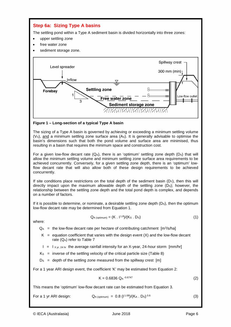
Step 6a: Sizing Type A basins The settling pond within a Type A sediment basin is divided horizontally into three zones: • upper settling zone • free water zone • sediment storage zone.
Figure 1 – Long-section of a typical Type A basin The sizing of a Type A basin is governed by achieving or exceeding a minimum settling volume (VS), and a minimum settling zone surface area (AS). It is generally advisable to optimise the basin’s dimensions such that both the pond volume and surface area are minimised, thus resulting in a basin that requires the minimum space and construction cost. For a given low-flow decant rate (QA), there is an ‘optimum’ settling zone depth (DS) that will allow the minimum settling volume and minimum settling zone surface area requirements to be achieved concurrently. Conversely, for a given settling zone depth, there is an ‘optimum’ low-flow decant rate that will also allow both of these design requirements to be achieved concurrently. If site conditions place restrictions on the total depth of the sediment basin (DT), then this will directly impact upon the maximum allowable depth of the settling zone (DS); however, the relationship between the settling zone depth and the total pond depth is complex, and depends on a number of factors. If it is possible to determine, or nominate, a desirable settling zone depth (DS), then the optimum low-flow decant rate may be determined from Equation 1. QA (optimum) = (K . I1.8)/(KS . DS) (1) where:
QA = the low-flow decant rate per hectare of contributing catchment [m3/s/ha]
K = equation coefficient that varies with the design event (X) and the low-flow decant rate (QA) refer to Table 7
I = I X yr, 24 hr the average rainfall intensity for an X-year, 24-hour storm [mm/hr]
KS = inverse of the settling velocity of the critical particle size (Table 8)
DS = depth of the settling zone measured from the spillway crest [m] For a 1 year ARI design event, the coefficient ‘K’ may be estimated from Equation 2: K = 0.6836 QA -0.6747 (2) This means the ‘optimum’ low-flow decant rate can be estimated from Equation 3. For a 1 yr ARI design: QA (optimum) = 0.8 (I1.08)/(KA . DS) 0.6 (3)
© IECA (Australasia) June 2018 Page 7
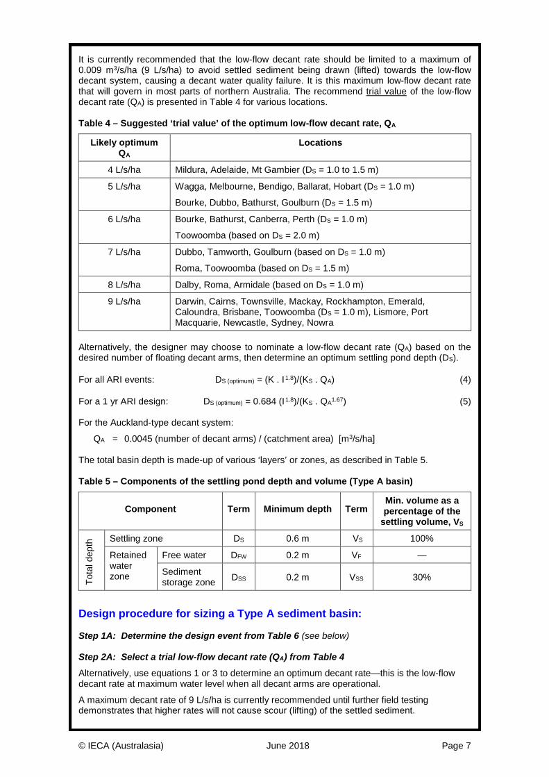
It is currently recommended that the low-flow decant rate should be limited to a maximum of 0.009 m3/s/ha (9 L/s/ha) to avoid settled sediment being drawn (lifted) towards the low-flow decant system, causing a decant water quality failure. It is this maximum low-flow decant rate that will govern in most parts of northern Australia. The recommend trial value of the low-flow decant rate (QA) is presented in Table 4 for various locations. Table 4 – Suggested ‘trial value’ of the optimum low-flow decant rate, QA
Likely optimum QA
Locations
4 L/s/ha Mildura, Adelaide, Mt Gambier (DS = 1.0 to 1.5 m)
5 L/s/ha Wagga, Melbourne, Bendigo, Ballarat, Hobart (DS = 1.0 m)
Bourke, Dubbo, Bathurst, Goulburn (DS = 1.5 m)
6 L/s/ha Bourke, Bathurst, Canberra, Perth (DS = 1.0 m)
Toowoomba (based on DS = 2.0 m)
7 L/s/ha Dubbo, Tamworth, Goulburn (based on DS = 1.0 m)
Roma, Toowoomba (based on DS = 1.5 m)
8 L/s/ha Dalby, Roma, Armidale (based on DS = 1.0 m)
9 L/s/ha Darwin, Cairns, Townsville, Mackay, Rockhampton, Emerald, Caloundra, Brisbane, Toowoomba (DS = 1.0 m), Lismore, Port Macquarie, Newcastle, Sydney, Nowra
Alternatively, the designer may choose to nominate a low-flow decant rate (QA) based on the desired number of floating decant arms, then determine an optimum settling pond depth (DS). For all ARI events: DS (optimum) = (K . I1.8)/(KS . QA) (4) For a 1 yr ARI design: DS (optimum) = 0.684 (I1.8)/(KS . QA1.67) (5) For the Auckland-type decant system:
QA = 0.0045 (number of decant arms) / (catchment area) [m3/s/ha] The total basin depth is made-up of various ‘layers’ or zones, as described in Table 5. Table 5 – Components of the settling pond depth and volume (Type A basin)
Component Term Minimum depth Term Min. volume as a percentage of the
settling volume, VS
Tota
l dep
th Settling zone DS 0.6 m VS 100%
Retained water zone
Free water DFW 0.2 m VF —
Sediment storage zone DSS 0.2 m VSS 30%
Design procedure for sizing a Type A sediment basin: Step 1A: Determine the design event from Table 6 (see below) Step 2A: Select a trial low-flow decant rate (QA) from Table 4
Alternatively, use equations 1 or 3 to determine an optimum decant rate—this is the low-flow decant rate at maximum water level when all decant arms are operational.
A maximum decant rate of 9 L/s/ha is currently recommended until further field testing demonstrates that higher rates will not cause scour (lifting) of the settled sediment.
© IECA (Australasia) June 2018 Page 8
Step 3A: Determine the optimum settling pond depth using either equations 4 or 5 Step 4A: Choose a ‘design’ settling zone depth (DS)
To obtain a sediment basin with the least volume and surface area, choose a settling zone depth equal to the optimum depth determined in Step 3A.
A minimum settling zone depth of 0.6 m is recommended because it ensures a pond residence time in the order of around 1.5 hours at the peak low-flow decant rate; and it reduces the risk of settled sediment being drawn up towards the floating decant arms.
If a greater settling zone depth is chosen, then the minimum surface area requirement will dominate, which will prevent the basin from being made smaller; however, the increased volume should improve the basin’s overall treatment efficiency. A maximum settling zone depth of 2.0 m is recommended.
If a smaller settling zone depth is chosen, then the required minimum settling zone volume will dictate the basin’s design, and the basin will have a surface area greater than that required by Step 5A. A settling zone depth of less than 0.6 m is not recommended. Step 5A: Calculate the minimum, average, settling zone surface area (AS)
Calculate the minimum, average, settling zone surface area based on Equation 11 (below) and the following design conditions:
• the expected settling rate of the treated sediment floc
• the expected water temperature within the pond during its critical operational phase.
It is noted that the water temperature within the settling pond is normally based on the temperature of rainwater at the time of year when rainfall intensity is the highest.
The minimum settling zone surface area as generated by Equation 11 is referred to as the ‘average’ surface area, meaning that when multiplied by the settling zone depth, it will equal the settling zone volume (VS). In most cases it can be assumed that this average surface area is the same as the surface area at the mid-depth of the settling zone (AMid); however, this is not always technically correct (even though the differences are usually minor).
Technically, the volume of the settling zone is not equal to the mid surface area times the depth, but instead is a product of the Simpson’s Rule, Equation 6. VS = (DS/6).(ATop + 4.AMid + ABase) (6) Step 6A: Calculate the minimum settling zone volume (VS) based on Equation 7 (below) Step 7A: Nominate the depth of the free water zone
The free water zone is used to separate the settled sediment from the low-flow decant system to prevent settled sediment from being drawn into the decant system at the start of the next storm.
The free water zone is required to be at least 0.2 m in depth. Step 8A: Check for the potential re-suspension of settled sediment
Currently the maximum allowable supernatant (clear liquor) velocity upstream of the overflow spillway has been set at 1.5 cm/s (0.015 m/s) based on decant testing of settled sludge blankets in wastewater treatment plants (best available information).
This means that a minimum free water depth of 0.2 m is recommended for the Auckland-type, low-flow decant system, which has a decant rate of 2.25 L/s/m (i.e. 4.5 L/s via a 2 m wide arm).
Designers should check that at the maximum decant rate (i.e. when all the decant arms are active) the velocity of the clear supernatant above the settled sediment blanket (assumed to be around 0.6 m below the water surface) does not exceed 1.5 cm/s.
If a multi-arm decant system is used, then this velocity check should be performed for each increment in the decant rate.
© IECA (Australasia) June 2018 Page 9
Step 9A: Determine the length and width of the settling zone
General requirement: settling zone length (LS) > 3 times its width (WS).
It is recommended that the length of the settling zone at the elevation of the spillway crest (i.e. at near maximum water level) should be at least three times the width of the settling zone at the elevation of the spillway crest.
For simplicity, designers may choose to set the length of the settling zone at the mid-elevation of the settling zone as equal to three times the mid-elevation width, then determine all other dimensions from these values. Step 10A: Determine the remaining dimensions of the sediment basin
Once the volume and dimensions of the settling zone are known, the remaining basin dimensions need to be determined based on the sizing requirements outlined in Table 5.
It is recommended that the bank slope of the inflow batter (adjacent the forebay) is 1 in 3.
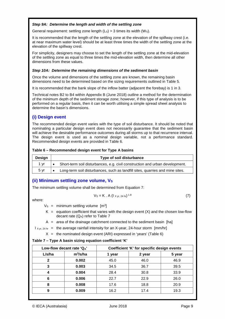
Technical notes B2 to B4 within Appendix B (June 2018) outline a method for the determination of the minimum depth of the sediment storage zone; however, if this type of analysis is to be performed on a regular basis, then it can be worth utilising a simple spread sheet analysis to determine the basin’s dimensions. (i) Design event The recommended design event varies with the type of soil disturbance. It should be noted that nominating a particular design event does not necessarily guarantee that the sediment basin will achieve the desirable performance outcomes during all storms up to that recurrence interval. The design event is used as a nominal design variable, not a performance standard. Recommended design events are provided in Table 6. Table 6 – Recommended design event for Type A basins
Design Type of soil disturbance 1 yr • Short-term soil disturbances, e.g. civil construction and urban development. 5 yr • Long-term soil disturbances, such as landfill sites, quarries and mine sites.
(ii) Minimum settling zone volume, VS The minimum settling volume shall be determined from Equation 7:
VS = K . A (I X yr, 24 hr) 1.8 (7) where: VS = minimum settling volume [m3] K = equation coefficient that varies with the design event (X) and the chosen low-flow
decant rate (QA) refer to Table 7 A = area of the drainage catchment connected to the sediment basin [ha] I X yr, 24 hr = the average rainfall intensity for an X-year, 24-hour storm [mm/hr] X = the nominated design event (ARI) expressed in ‘years’ (Table 6)
Table 7 – Type A basin sizing equation coefficient ‘K’
Low-flow decant rate ‘QA’ Coefficient ‘K’ for specific design events L/s/ha m3/s/ha 1 year 2 year 5 year
2 0.002 45.0 46.0 46.9 3 0.003 34.5 36.7 39.5 4 0.004 28.4 30.8 33.9 6 0.006 22.7 22.9 26.0 8 0.008 17.6 18.8 20.9 9 0.009 16.2 17.4 19.3
© IECA (Australasia) June 2018 Page 10
For low-flow decants outside of the range of 2 to 9 L/s/ha, the value of the equation coefficient (K) can be estimated using the following equations; however, precedence must be given to the values presented in Table 7. X = 1 year ARI: K = 0.684 QA -0.675 (8)
X = 2 year ARI: K = 0.784 QA -0.660 (9)
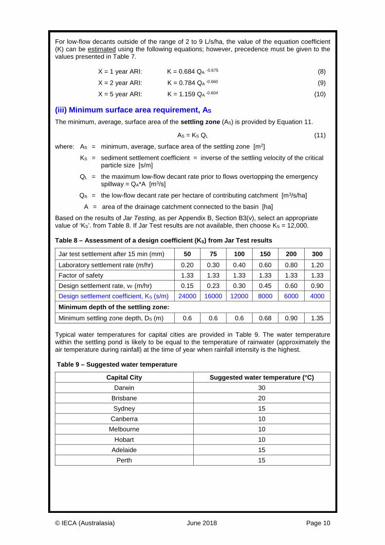
X = 5 year ARI: K = 1.159 QA -0.604 (10) (iii) Minimum surface area requirement, AS The minimum, average, surface area of the settling zone (AS) is provided by Equation 11.
AS = KS QL (11)
where: AS = minimum, average, surface area of the settling zone [m2]
KS = sediment settlement coefficient = inverse of the settling velocity of the critical particle size [s/m]
QL = the maximum low-flow decant rate prior to flows overtopping the emergency spillway = QA*A [m3/s]
QA = the low-flow decant rate per hectare of contributing catchment [m3/s/ha]
A = area of the drainage catchment connected to the basin [ha]
Based on the results of Jar Testing, as per Appendix B, Section B3(v), select an appropriate value of ‘KS’. from Table 8. If Jar Test results are not available, then choose KS = 12,000. Table 8 – Assessment of a design coefficient (KS) from Jar Test results
Jar test settlement after 15 min (mm) 50 75 100 150 200 300 Laboratory settlement rate (m/hr) 0.20 0.30 0.40 0.60 0.80 1.20 Factor of safety 1.33 1.33 1.33 1.33 1.33 1.33 Design settlement rate, vF (m/hr) 0.15 0.23 0.30 0.45 0.60 0.90 Design settlement coefficient, KS (s/m) 24000 16000 12000 8000 6000 4000 Minimum depth of the settling zone: Minimum settling zone depth, DS (m) 0.6 0.6 0.6 0.68 0.90 1.35
Typical water temperatures for capital cities are provided in Table 9. The water temperature within the settling pond is likely to be equal to the temperature of rainwater (approximately the air temperature during rainfall) at the time of year when rainfall intensity is the highest. Table 9 – Suggested water temperature
Capital City Suggested water temperature (°C) Darwin 30
Brisbane 20 Sydney 15
Canberra 10 Melbourne 10
Hobart 10 Adelaide 15
Perth 15
© IECA (Australasia) June 2018 Page 11
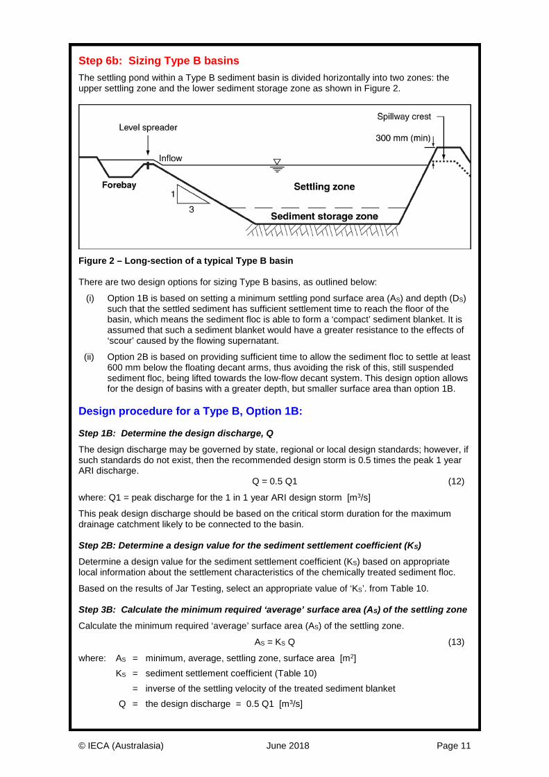
Step 6b: Sizing Type B basins The settling pond within a Type B sediment basin is divided horizontally into two zones: the upper settling zone and the lower sediment storage zone as shown in Figure 2.
Figure 2 – Long-section of a typical Type B basin There are two design options for sizing Type B basins, as outlined below:
(i) Option 1B is based on setting a minimum settling pond surface area (AS) and depth (DS) such that the settled sediment has sufficient settlement time to reach the floor of the basin, which means the sediment floc is able to form a ‘compact’ sediment blanket. It is assumed that such a sediment blanket would have a greater resistance to the effects of ‘scour’ caused by the flowing supernatant.
(ii) Option 2B is based on providing sufficient time to allow the sediment floc to settle at least 600 mm below the floating decant arms, thus avoiding the risk of this, still suspended sediment floc, being lifted towards the low-flow decant system. This design option allows for the design of basins with a greater depth, but smaller surface area than option 1B.
Design procedure for a Type B, Option 1B: Step 1B: Determine the design discharge, Q
The design discharge may be governed by state, regional or local design standards; however, if such standards do not exist, then the recommended design storm is 0.5 times the peak 1 year ARI discharge. Q = 0.5 Q1 (12)
where: Q1 = peak discharge for the 1 in 1 year ARI design storm [m3/s]
This peak design discharge should be based on the critical storm duration for the maximum drainage catchment likely to be connected to the basin. Step 2B: Determine a design value for the sediment settlement coefficient (KS)
Determine a design value for the sediment settlement coefficient (KS) based on appropriate local information about the settlement characteristics of the chemically treated sediment floc.
Based on the results of Jar Testing, select an appropriate value of ‘KS’. from Table 10. Step 3B: Calculate the minimum required ‘average’ surface area (AS) of the settling zone
Calculate the minimum required ‘average’ surface area (AS) of the settling zone.
AS = KS Q (13)
where: AS = minimum, average, settling zone, surface area [m2] KS = sediment settlement coefficient (Table 10) = inverse of the settling velocity of the treated sediment blanket Q = the design discharge = 0.5 Q1 [m3/s]
© IECA (Australasia) June 2018 Page 12
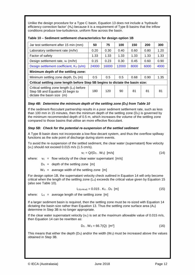
Unlike the design procedure for a Type C basin, Equation 13 does not include a ‘hydraulic efficiency correction factor’ (He) because it is a requirement of Type B basins that the inflow conditions produce low-turbulence, uniform flow across the basin. Table 10 – Sediment settlement characteristics for design option 1B
Jar test settlement after 15 min (mm) 50 75 100 150 200 300 Laboratory settlement rate (m/hr) 0.20 0.30 0.40 0.60 0.80 1.20 Factor of safety 1.33 1.33 1.33 1.33 1.33 1.33 Design settlement rate, vF (m/hr) 0.15 0.23 0.30 0.45 0.60 0.90 Design settlement coefficient, KS (s/m) 24000 16000 12000 8000 6000 4000 Minimum depth of the settling zone: Minimum settling zone depth, DS (m) 0.5 0.5 0.5 0.68 0.90 1.35 Critical settling zone length before Step 5B begins to dictate the basin size: Critical settling zone length (LS) before Step 5B and Equation 16 begin to dictate the basin size (m)
180 120 90 81 81 81
Step 4B: Determine the minimum depth of the settling zone (DS) from Table 10
If the sediment-flocculant partnership results in a poor sediment settlement rate, such as less than 100 mm in 15 minutes, then the minimum depth of the settling zone (DS) is governed by the minimum recommended depth of 0.5 m, which increases the volume of the settling zone compared to those basins that utilise an more effective flocculant. Step 5B: Check for the potential re-suspension of the settled sediment
A Type B basin does not incorporate a low-flow decant system, and thus the overflow spillway functions as the sole point of discharge during storm events.
To avoid the re-suspension of the settled sediment, the clear water (supernatant) flow velocity (vC) should not exceed 0.015 m/s (1.5 cm/s).
vC = Q/(DS . WS) [m/s] (14)
where: vC = flow velocity of the clear water supernatant [m/s]
DS = depth of the settling zone [m]
WS = average width of the settling zone [m]
For design option 1B, the supernatant velocity check outlined in Equation 14 will only become critical when the length of the settling zone (LS) exceeds the critical value given by Equation 15 (also see Table 10).
LS(critical) = 0.015 . KS . DS [m] (15)
where: LS = average length of the settling zone [m] If a larger sediment basin is required, then the settling zone must be re-sized with Equation 14 dictating the basin size rather than Equation 13. Thus the settling zone surface area (AS) determine in Step 3B is no longer appropriate.
If the clear water supernatant velocity (vC) is set at the maximum allowable value of 0.015 m/s, then Equation 14 can be rewritten as:
DS . WS = 66.7(Q) [m2] (16) This means that either the depth (DS) and/or the width (WS) must be increased above the values obtained in Step 3B.
© IECA (Australasia) June 2018 Page 13
Increasing the depth (DS) means increasing the basin volume, but not the surface area (AS).
Increasing the width (WS) means increasing the basin volume, length (LS) and surface area (AS).
It is recommended that the width of the settling zone at the top water level (WT) should not exceed a third of the length of the settling zone at the top water level (LT).
For convenience it is conservative to set the average length of the settling zone (LS) as three times the average width of the settling zone (WS), thus:
LS = 3 WS (17) Step 6B: Determine the width of the overflow spillway
In order to reduce the risk of the re-suspension of settled sediment, the overflow spillway on Type B basins should be the maximum practical width.
Ideally the maximum allowable supernatant velocity upstream of the overflow spillway should be 1.5 cm/s (0.015 m/s) during the basin’s design storm (i.e. Q = 0.5 Q1); however, this may not always be practical for Type B basins. In such cases, designers should take all reasonable measures to achieve a spillway crest width just less than the top width of the settling zone. Design procedure for a Type B, Option 2B: Step 1B: Determine the design discharge, Q
The design discharge may be governed by state, regional or local design standards; however, if such standards do not exist, then the recommended design storm is 0.5 times the peak 1 year ARI discharge.
Q = 0.5 Q1 (18)
where: Q1 = peak discharge for the 1 in 1 year ARI design storm [m3/s]
This peak design discharge should be based on the critical storm duration for the maximum drainage catchment likely to be connected to the basin. Step 2B: Nominate the depth of the settling zone (DS), and the floc settling depth (DF)
For this design option, the depth of the settling zone is not limited to the nominated floc settling depth (DF) as used in Step 2B above.
DF ≥ 0.6 (19)
The minimum settling zone depth is 0.6 m, which is an increase from the 0.5 m used in design option 1B. This is because in this design option the sediment floc is considered to be still settling as it approaches the overflow spillway, whereas in design option 1B the sediment floc is assumed to have fully settled, and thus more resistant to disturbance.
DS is the effective depth of the settling zone (i.e. the maximum water depth above the sediment storage zone). Increasing this depth will reduce the forward velocity of the settling sediment floc, which increases the residence time and therefore the time available for the sediment floc to settling the required floc settling depth, DF.
DS ≥ DF (20)
The nominated settling zone depth can be within the range of 0.6 to 2.0 m. The greater the nominated depth, the smaller the required surface area of the basin, but the volume of the settling zone (VS), and consequently the total basin volume, will essentially remain unchanged. Step 3B: Calculate the ‘average’ surface area (AS) of the settling zone
The required ‘average’ surface area (AS) of the settling zone is given by Equation 21.
AS = (DF/DS) KS Q (21)
where: AS = minimum, average, settling zone, surface area [m2]
KS = sediment settlement coefficient (Table 11)
= inverse of the settling velocity of the treated sediment blanket
© IECA (Australasia) June 2018 Page 14
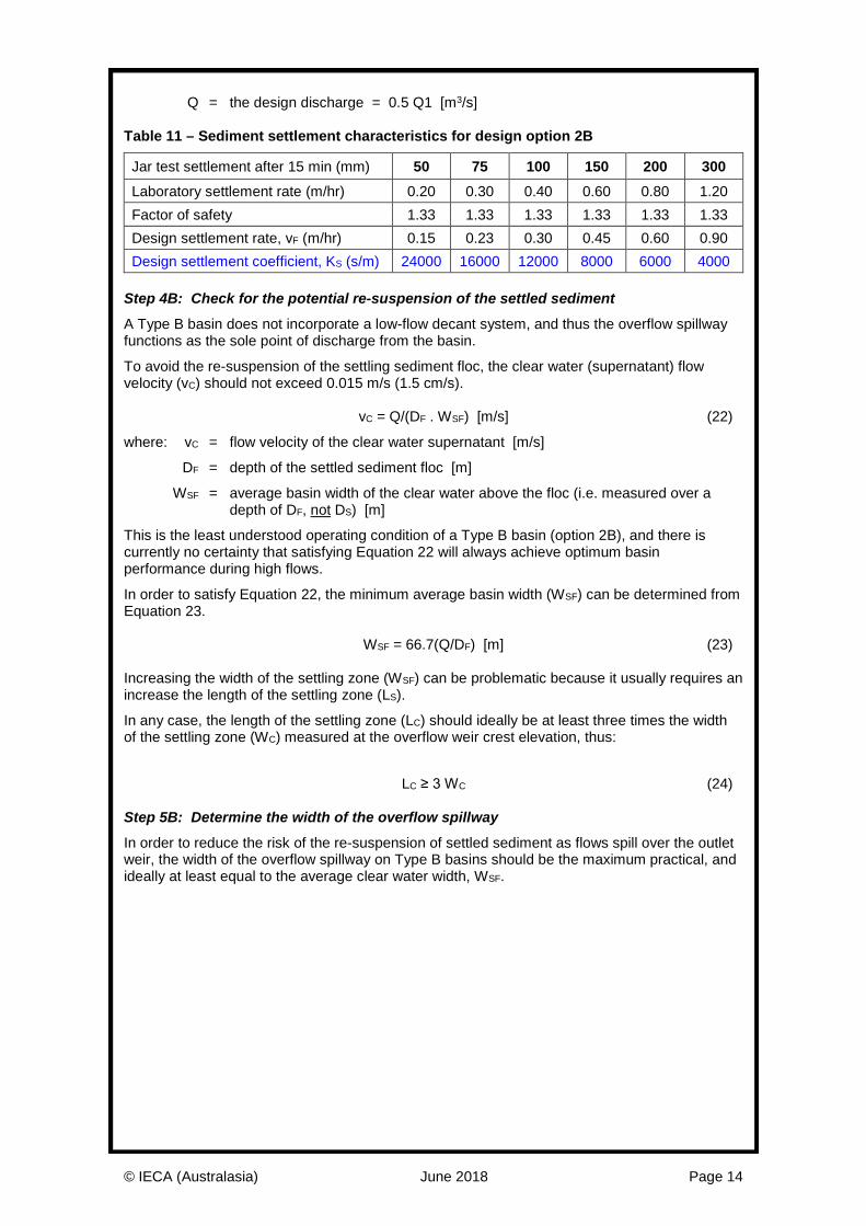
Q = the design discharge = 0.5 Q1 [m3/s] Table 11 – Sediment settlement characteristics for design option 2B
Jar test settlement after 15 min (mm) 50 75 100 150 200 300 Laboratory settlement rate (m/hr) 0.20 0.30 0.40 0.60 0.80 1.20 Factor of safety 1.33 1.33 1.33 1.33 1.33 1.33 Design settlement rate, vF (m/hr) 0.15 0.23 0.30 0.45 0.60 0.90 Design settlement coefficient, KS (s/m) 24000 16000 12000 8000 6000 4000
Step 4B: Check for the potential re-suspension of the settled sediment
A Type B basin does not incorporate a low-flow decant system, and thus the overflow spillway functions as the sole point of discharge from the basin.
To avoid the re-suspension of the settling sediment floc, the clear water (supernatant) flow velocity (vC) should not exceed 0.015 m/s (1.5 cm/s). vC = Q/(DF . WSF) [m/s] (22)
where: vC = flow velocity of the clear water supernatant [m/s]
DF = depth of the settled sediment floc [m]
WSF = average basin width of the clear water above the floc (i.e. measured over a depth of DF, not DS) [m]
This is the least understood operating condition of a Type B basin (option 2B), and there is currently no certainty that satisfying Equation 22 will always achieve optimum basin performance during high flows.
In order to satisfy Equation 22, the minimum average basin width (WSF) can be determined from Equation 23. WSF = 66.7(Q/DF) [m] (23) Increasing the width of the settling zone (WSF) can be problematic because it usually requires an increase the length of the settling zone (LS).
In any case, the length of the settling zone (LC) should ideally be at least three times the width of the settling zone (WC) measured at the overflow weir crest elevation, thus:
LC ≥ 3 WC (24) Step 5B: Determine the width of the overflow spillway
In order to reduce the risk of the re-suspension of settled sediment as flows spill over the outlet weir, the width of the overflow spillway on Type B basins should be the maximum practical, and ideally at least equal to the average clear water width, WSF.
© IECA (Australasia) June 2018 Page 15
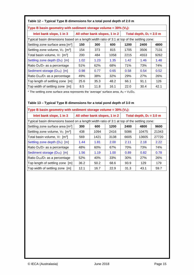
Table 12 – Typical Type B dimensions for a total pond depth of 2.0 m
Type B basin geometry with sediment storage volume = 30% (VS):
Inlet bank slope, 1 in 3 All other bank slopes, 1 in 2 Total depth, DT = 2.0 m Typical basin dimensions based on a length:width ratio of 3:1 at top of the settling zone: Settling zone surface area [m2] 150 300 600 1200 2400 4800 Settling zone volume, VS [m3] 154 373 815 1705 3506 7131 Total basin volume, VT [m3] 200 484 1058 2215 4553 9262 Settling zone depth (DS) [m] 1.02 1.23 1.35 1.42 1.46 1.48 Ratio DS/DT as a percentage 51% 62% 68% 71% 73% 74% Sediment storage (DSS) [m] 0.98 0.77 0.65 0.58 0.54 0.52 Ratio DSS/DT as a percentage 49% 38% 32% 29% 27% 26% Top length of settling zone [m] 25.6 35.3 48.2 66.1 91.1 126 Top width of settling zone [m] 8.5 11.8 16.1 22.0 30.4 42.1 * The settling zone surface area represents the ‘average’ surface area, AS = VS/DS. Table 13 – Typical Type B dimensions for a total pond depth of 3.0 m
Type B basin geometry with sediment storage volume = 30% (VS):
Inlet bank slope, 1 in 3 All other bank slopes, 1 in 2 Total depth, DT = 3.0 m Typical basin dimensions based on a length:width ratio of 3:1 at top of the settling zone: Settling zone surface area [m2] 300 600 1200 2400 4800 9600 Settling zone volume, VS [m3] 438 1094 2416 5086 10475 21343 Total basin volume, VT [m3] 569 1421 3138 6605 13605 27720 Settling zone depth (DS) [m] 1.44 1.81 2.00 2.11 2.18 2.22 Ratio DS/DT as a percentage 48% 60% 67% 70% 73% 74% Sediment storage (DSS) [m] 1.56 1.19 1.00 0.89 0.82 0.78 Ratio DSS/DT as a percentage 52% 40% 33% 30% 27% 26% Top length of settling zone [m] 36.2 50.2 68.6 93.9 129 179 Top width of settling zone [m] 12.1 16.7 22.9 31.3 43.1 59.7
© IECA (Australasia) June 2018 Page 16
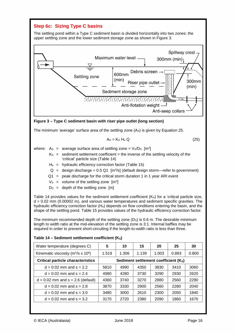
Step 6c: Sizing Type C basins The settling pond within a Type C sediment basin is divided horizontally into two zones: the upper settling zone and the lower sediment storage zone as shown in Figure 3.
Figure 3 – Type C sediment basin with riser pipe outlet (long section) The minimum ‘average’ surface area of the settling zone (AS) is given by Equation 25. AS = KS He Q (25) where: AS = average surface area of settling zone = VS/DS [m2] KS = sediment settlement coefficient = the inverse of the settling velocity of the
‘critical’ particle size (Table 14) He = hydraulic efficiency correction factor (Table 15) Q = design discharge = 0.5 Q1 [m3/s] (default design storm—refer to government) Q1 = peak discharge for the critical storm duration 1 in 1 year ARI event VS = volume of the settling zone [m3] DS = depth of the settling zone [m] Table 14 provides values for the sediment settlement coefficient (KA) for a ‘critical particle size, d = 0.02 mm (0.00002 m), and various water temperatures and sediment specific gravities. The hydraulic efficiency correction factor (He) depends on flow conditions entering the basin, and the shape of the settling pond. Table 15 provides values of the hydraulic efficiency correction factor. The minimum recommended depth of the settling zone (DS) is 0.6 m. The desirable minimum length to width ratio at the mid-elevation of the settling zone is 3:1. Internal baffles may be required in order to prevent short-circuiting if the length-to-width ratio is less than three. Table 14 – Sediment settlement coefficient (KS)
Water temperature (degrees C) 5 10 15 20 25 30
Kinematic viscosity (m2/s x 106) 1.519 1.306 1.139 1.003 0.893 0.800
Critical particle characteristics Sediment settlement coefficient (KS) d = 0.02 mm and s = 2.2 5810 4990 4350 3830 3410 3060 d = 0.02 mm and s = 2.4 4980 4280 3730 3290 2930 2620
d = 0.02 mm and s = 2.6 (default) 4360 3740 3270 2880 2560 2290 d = 0.02 mm and s = 2.8 3870 3330 2900 2560 2280 2040 d = 0.02 mm and s = 3.0 3480 3000 2610 2300 2050 1840 d = 0.02 mm and s = 3.2 3170 2720 2380 2090 1860 1670
© IECA (Australasia) June 2018 Page 17
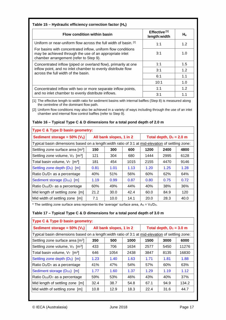
Table 15 – Hydraulic efficiency correction factor (He)
Flow condition within basin Effective [1] length:width He
Uniform or near-uniform flow across the full width of basin. [2] For basins with concentrated inflow, uniform flow conditions may be achieved through the use of an appropriate inlet chamber arrangement (refer to Step 9).
1:1 1.2
3:1 1.0
Concentrated inflow (piped or overland flow), primarily at one inflow point, and no inlet chamber to evenly distribute flow across the full width of the basin.
1:1 1.5 3:1 1.2 6:1 1.1 10:1 1.0
Concentrated inflow with two or more separate inflow points, and no inlet chamber to evenly distribute inflows.
1:1 1.2 3:1 1.1
[1] The effective length to width ratio for sediment basins with internal baffles (Step 8) is measured along the centreline of the dominant flow path.
[2] Uniform flow conditions may also be achieved in a variety of ways including through the use of an inlet chamber and internal flow control baffles (refer to Step 9).
Table 16 – Typical Type C & D dimensions for a total pond depth of 2.0 m
Type C & Type D basin geometry:
Sediment storage = 50% (VS) All bank slopes, 1 in 2 Total depth, DT = 2.0 m Typical basin dimensions based on a length:width ratio of 3:1 at mid-elevation of settling zone: Settling zone surface area [m2] 150 300 600 1200 2400 4800 Settling zone volume, VS [m3] 121 304 680 1444 2995 6128 Total basin volume, VT [m3] 181 454 1015 2155 4470 9146 Settling zone depth (DS) [m] 0.81 1.01 1.13 1.20 1.25 1.28 Ratio DS/DT as a percentage 40% 51% 56% 60% 62% 64% Sediment storage (DSS) [m] 1.19 0.99 0.87 0.80 0.75 0.72 Ratio DSS/DT as a percentage 60% 49% 44% 40% 38% 36% Mid length of settling zone [m] 21.2 30.0 42.4 60.0 84.9 120 Mid width of settling zone [m] 7.1 10.0 14.1 20.0 28.3 40.0 * The settling zone surface area represents the ‘average’ surface area, AS = VS/DS. Table 17 – Typical Type C & D dimensions for a total pond depth of 3.0 m
Type C & Type D basin geometry:
Sediment storage = 50% (VS) All bank slopes, 1 in 2 Total depth, DT = 3.0 m Typical basin dimensions based on a length:width ratio of 3:1 at mid-elevation of settling zone: Settling zone surface area [m2] 350 500 1000 1500 3000 6000 Settling zone volume, VS [m3] 433 706 1634 2577 5450 11276 Total basin volume, VT [m3] 646 1054 2438 3847 8135 16830 Settling zone depth (DS) [m] 1.23 1.40 1.63 1.71 1.81 1.88 Ratio DS/DT as a percentage 41% 47% 54% 57% 60% 63% Sediment storage (DSS) [m] 1.77 1.60 1.37 1.29 1.19 1.12 Ratio DSS/DT as a percentage 59% 53% 46% 43% 40% 37% Mid length of settling zone [m] 32.4 38.7 54.8 67.1 94.9 134.2 Mid width of settling zone [m] 10.8 12.9 18.3 22.4 31.6 44.7
© IECA (Australasia) June 2018 Page 18
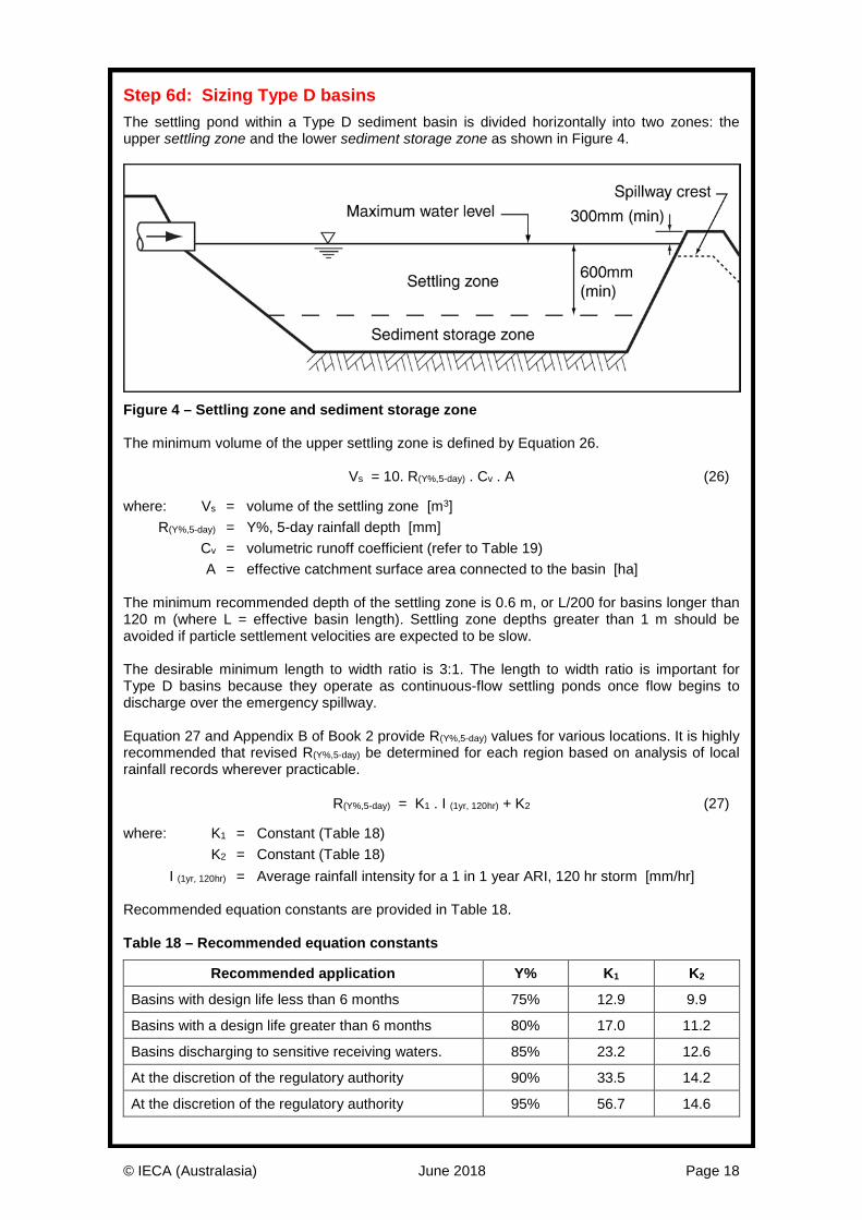
Step 6d: Sizing Type D basins The settling pond within a Type D sediment basin is divided horizontally into two zones: the upper settling zone and the lower sediment storage zone as shown in Figure 4.
Figure 4 – Settling zone and sediment storage zone The minimum volume of the upper settling zone is defined by Equation 26.
Vs = 10. R(Y%,5-day) . Cv . A (26)
where: Vs = volume of the settling zone [m3] R(Y%,5-day) = Y%, 5-day rainfall depth [mm] Cv = volumetric runoff coefficient (refer to Table 19) A = effective catchment surface area connected to the basin [ha] The minimum recommended depth of the settling zone is 0.6 m, or L/200 for basins longer than 120 m (where L = effective basin length). Settling zone depths greater than 1 m should be avoided if particle settlement velocities are expected to be slow. The desirable minimum length to width ratio is 3:1. The length to width ratio is important for Type D basins because they operate as continuous-flow settling ponds once flow begins to discharge over the emergency spillway. Equation 27 and Appendix B of Book 2 provide R(Y%,5-day) values for various locations. It is highly recommended that revised R(Y%,5-day) be determined for each region based on analysis of local rainfall records wherever practicable. R(Y%,5-day) = K1 . I (1yr, 120hr) + K2 (27)
where: K1 = Constant (Table 18) K2 = Constant (Table 18) I (1yr, 120hr) = Average rainfall intensity for a 1 in 1 year ARI, 120 hr storm [mm/hr] Recommended equation constants are provided in Table 18. Table 18 – Recommended equation constants
Recommended application Y% K1 K2
Basins with design life less than 6 months 75% 12.9 9.9
Basins with a design life greater than 6 months 80% 17.0 11.2
Basins discharging to sensitive receiving waters. 85% 23.2 12.6
At the discretion of the regulatory authority 90% 33.5 14.2
At the discretion of the regulatory authority 95% 56.7 14.6
© IECA (Australasia) June 2018 Page 19
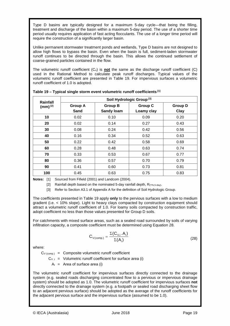
Type D basins are typically designed for a maximum 5-day cycle—that being the filling, treatment and discharge of the basin within a maximum 5-day period. The use of a shorter time period usually requires application of fast acting flocculants. The use of a longer time period will require the construction of a significantly larger basin. Unlike permanent stormwater treatment ponds and wetlands, Type D basins are not designed to allow high flows to bypass the basin. Even when the basin is full, sediment-laden stormwater runoff continues to be directed through the basin. This allows the continued settlement of coarse-grained particles contained in the flow. The volumetric runoff coefficient (Cv) is not the same as the discharge runoff coefficient (C) used in the Rational Method to calculate peak runoff discharges. Typical values of the volumetric runoff coefficient are presented in Table 19. For impervious surfaces a volumetric runoff coefficient of 1.0 is adopted. Table 19 – Typical single storm event volumetric runoff coefficients [1]
Rainfall (mm) [2]
Soil Hydrologic Group [3] Group A
Sand Group B
Sandy loam Group C
Loamy clay Group D
Clay 10 0.02 0.10 0.09 0.20 20 0.02 0.14 0.27 0.43 30 0.08 0.24 0.42 0.56 40 0.16 0.34 0.52 0.63 50 0.22 0.42 0.58 0.69 60 0.28 0.48 0.63 0.74 70 0.33 0.53 0.67 0.77 80 0.36 0.57 0.70 0.79 90 0.41 0.60 0.73 0.81 100 0.45 0.63 0.75 0.83
Notes: [1] Sourced from Fifield (2001) and Landcom (2004). [2] Rainfall depth based on the nominated 5-day rainfall depth, R(Y%,5-day). [3] Refer to Section A3.1 of Appendix A for the definition of Soil Hydrologic Group. The coefficients presented in Table 19 apply only to the pervious surfaces with a low to medium gradient (i.e. < 10% slope). Light to heavy clays compacted by construction equipment should attract a volumetric runoff coefficient of 1.0. For loamy soils compacted by construction traffic, adopt coefficient no less than those values presented for Group D soils. For catchments with mixed surface areas, such as a sealed road surrounded by soils of varying infiltration capacity, a composite coefficient must be determined using Equation 28.
(28)
where: CV (comp.) = Composite volumetric runoff coefficient CV ,i = Volumetric runoff coefficient for surface area (i) Ai = Area of surface area (i) The volumetric runoff coefficient for impervious surfaces directly connected to the drainage system (e.g. sealed roads discharging concentrated flow to a pervious or impervious drainage system) should be adopted as 1.0. The volumetric runoff coefficient for impervious surfaces not directly connected to the drainage system (e.g. a footpath or sealed road discharging sheet flow to an adjacent pervious surface) should be adopted as the average of the runoff coefficients for the adjacent pervious surface and the impervious surface (assumed to be 1.0).
CC A
AV compV i i
i( .)
,( . )( )
=ΣΣ
© IECA (Australasia) June 2018 Page 20
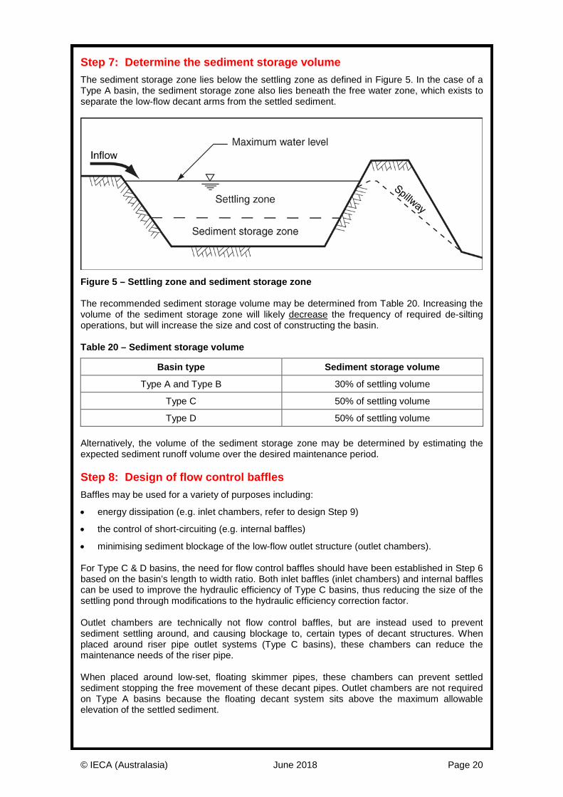
Step 7: Determine the sediment storage volume The sediment storage zone lies below the settling zone as defined in Figure 5. In the case of a Type A basin, the sediment storage zone also lies beneath the free water zone, which exists to separate the low-flow decant arms from the settled sediment.
Figure 5 – Settling zone and sediment storage zone The recommended sediment storage volume may be determined from Table 20. Increasing the volume of the sediment storage zone will likely decrease the frequency of required de-silting operations, but will increase the size and cost of constructing the basin. Table 20 – Sediment storage volume
Basin type Sediment storage volume
Type A and Type B 30% of settling volume
Type C 50% of settling volume
Type D 50% of settling volume
Alternatively, the volume of the sediment storage zone may be determined by estimating the expected sediment runoff volume over the desired maintenance period. Step 8: Design of flow control baffles Baffles may be used for a variety of purposes including:
• energy dissipation (e.g. inlet chambers, refer to design Step 9)
• the control of short-circuiting (e.g. internal baffles)
• minimising sediment blockage of the low-flow outlet structure (outlet chambers). For Type C & D basins, the need for flow control baffles should have been established in Step 6 based on the basin’s length to width ratio. Both inlet baffles (inlet chambers) and internal baffles can be used to improve the hydraulic efficiency of Type C basins, thus reducing the size of the settling pond through modifications to the hydraulic efficiency correction factor. Outlet chambers are technically not flow control baffles, but are instead used to prevent sediment settling around, and causing blockage to, certain types of decant structures. When placed around riser pipe outlet systems (Type C basins), these chambers can reduce the maintenance needs of the riser pipe. When placed around low-set, floating skimmer pipes, these chambers can prevent settled sediment stopping the free movement of these decant pipes. Outlet chambers are not required on Type A basins because the floating decant system sits above the maximum allowable elevation of the settled sediment.
© IECA (Australasia) June 2018 Page 21
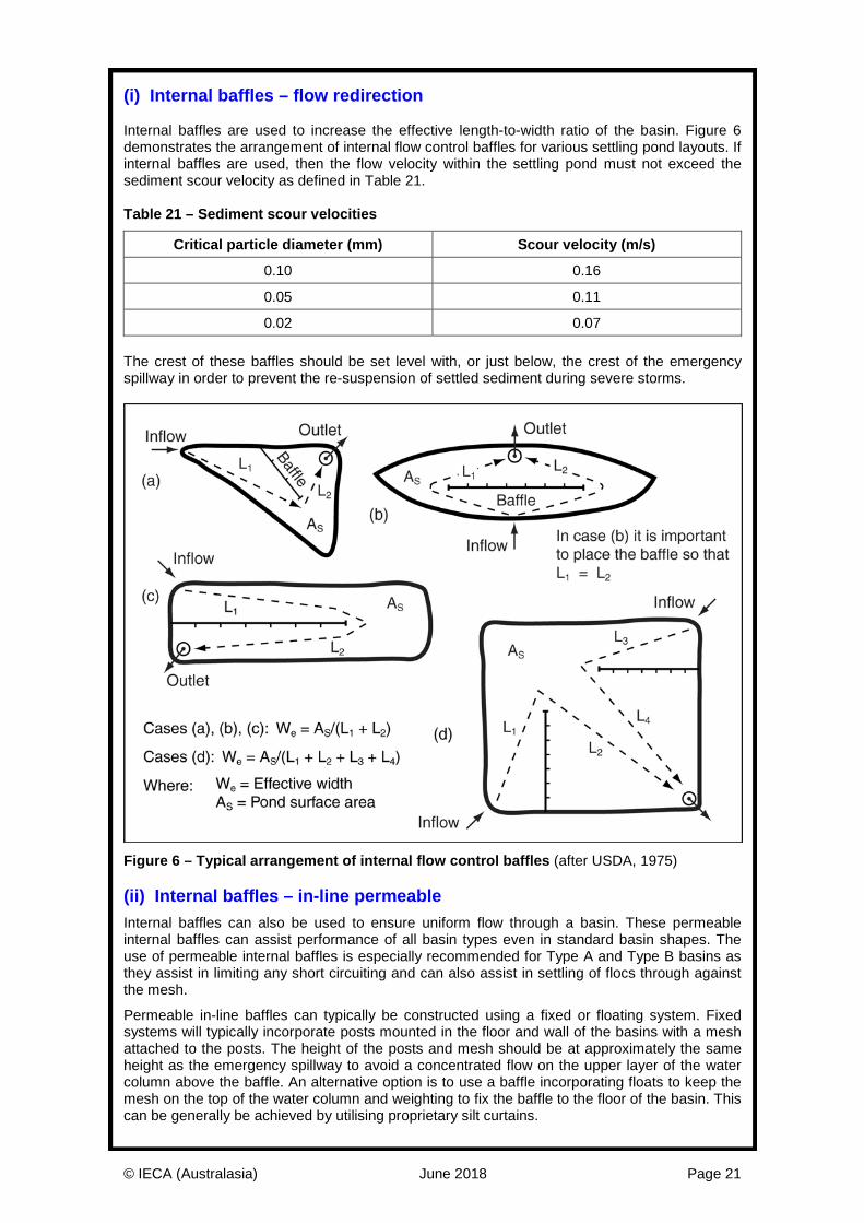
(i) Internal baffles – flow redirection Internal baffles are used to increase the effective length-to-width ratio of the basin. Figure 6 demonstrates the arrangement of internal flow control baffles for various settling pond layouts. If internal baffles are used, then the flow velocity within the settling pond must not exceed the sediment scour velocity as defined in Table 21. Table 21 – Sediment scour velocities
Critical particle diameter (mm) Scour velocity (m/s)
0.10 0.16
0.05 0.11
0.02 0.07 The crest of these baffles should be set level with, or just below, the crest of the emergency spillway in order to prevent the re-suspension of settled sediment during severe storms.
Figure 6 – Typical arrangement of internal flow control baffles (after USDA, 1975) (ii) Internal baffles – in-line permeable Internal baffles can also be used to ensure uniform flow through a basin. These permeable internal baffles can assist performance of all basin types even in standard basin shapes. The use of permeable internal baffles is especially recommended for Type A and Type B basins as they assist in limiting any short circuiting and can also assist in settling of flocs through against the mesh.
Permeable in-line baffles can typically be constructed using a fixed or floating system. Fixed systems will typically incorporate posts mounted in the floor and wall of the basins with a mesh attached to the posts. The height of the posts and mesh should be at approximately the same height as the emergency spillway to avoid a concentrated flow on the upper layer of the water column above the baffle. An alternative option is to use a baffle incorporating floats to keep the mesh on the top of the water column and weighting to fix the baffle to the floor of the basin. This can be generally be achieved by utilising proprietary silt curtains.
© IECA (Australasia) June 2018 Page 22
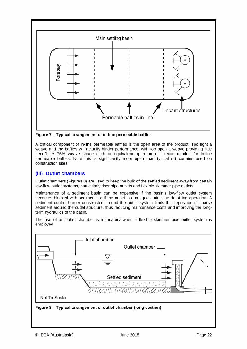
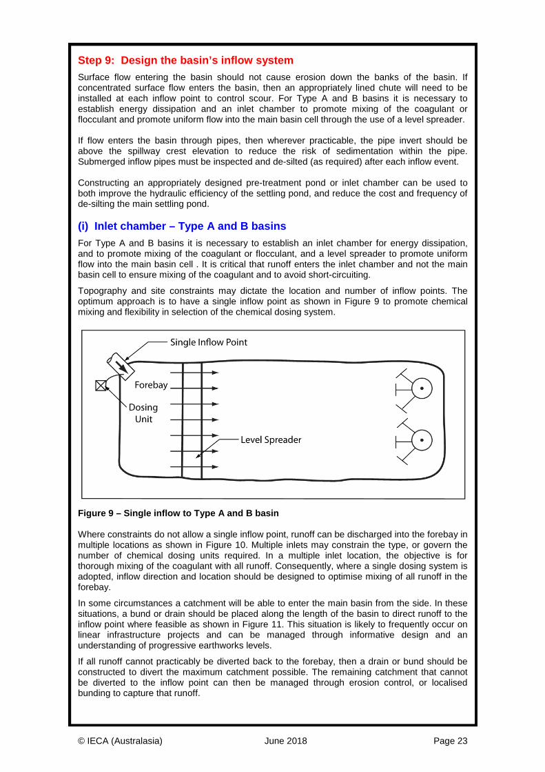
Figure 7 – Typical arrangement of in-line permeable baffles A critical component of in-line permeable baffles is the open area of the product. Too tight a weave and the baffles will actually hinder performance, with too open a weave providing little benefit. A 75% weave shade cloth or equivalent open area is recommended for in-line permeable baffles. Note this is significantly more open than typical silt curtains used on construction sites. (iii) Outlet chambers Outlet chambers (Figures 8) are used to keep the bulk of the settled sediment away from certain low-flow outlet systems, particularly riser pipe outlets and flexible skimmer pipe outlets.
Maintenance of a sediment basin can be expensive if the basin’s low-flow outlet system becomes blocked with sediment, or if the outlet is damaged during the de-silting operation. A sediment control barrier constructed around the outlet system limits the deposition of coarse sediment around the outlet structure, thus reducing maintenance costs and improving the long-term hydraulics of the basin.
The use of an outlet chamber is mandatory when a flexible skimmer pipe outlet system is employed.
Figure 8 – Typical arrangement of outlet chamber (long section)
© IECA (Australasia) June 2018 Page 23
Step 9: Design the basin’s inflow system Surface flow entering the basin should not cause erosion down the banks of the basin. If concentrated surface flow enters the basin, then an appropriately lined chute will need to be installed at each inflow point to control scour. For Type A and B basins it is necessary to establish energy dissipation and an inlet chamber to promote mixing of the coagulant or flocculant and promote uniform flow into the main basin cell through the use of a level spreader. If flow enters the basin through pipes, then wherever practicable, the pipe invert should be above the spillway crest elevation to reduce the risk of sedimentation within the pipe. Submerged inflow pipes must be inspected and de-silted (as required) after each inflow event. Constructing an appropriately designed pre-treatment pond or inlet chamber can be used to both improve the hydraulic efficiency of the settling pond, and reduce the cost and frequency of de-silting the main settling pond. (i) Inlet chamber – Type A and B basins For Type A and B basins it is necessary to establish an inlet chamber for energy dissipation, and to promote mixing of the coagulant or flocculant, and a level spreader to promote uniform flow into the main basin cell . It is critical that runoff enters the inlet chamber and not the main basin cell to ensure mixing of the coagulant and to avoid short-circuiting.
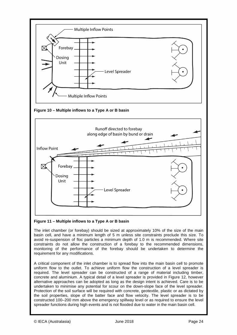
Topography and site constraints may dictate the location and number of inflow points. The optimum approach is to have a single inflow point as shown in Figure 9 to promote chemical mixing and flexibility in selection of the chemical dosing system.
Figure 9 – Single inflow to Type A and B basin Where constraints do not allow a single inflow point, runoff can be discharged into the forebay in multiple locations as shown in Figure 10. Multiple inlets may constrain the type, or govern the number of chemical dosing units required. In a multiple inlet location, the objective is for thorough mixing of the coagulant with all runoff. Consequently, where a single dosing system is adopted, inflow direction and location should be designed to optimise mixing of all runoff in the forebay.
In some circumstances a catchment will be able to enter the main basin from the side. In these situations, a bund or drain should be placed along the length of the basin to direct runoff to the inflow point where feasible as shown in Figure 11. This situation is likely to frequently occur on linear infrastructure projects and can be managed through informative design and an understanding of progressive earthworks levels.
If all runoff cannot practicably be diverted back to the forebay, then a drain or bund should be constructed to divert the maximum catchment possible. The remaining catchment that cannot be diverted to the inflow point can then be managed through erosion control, or localised bunding to capture that runoff.
© IECA (Australasia) June 2018 Page 24
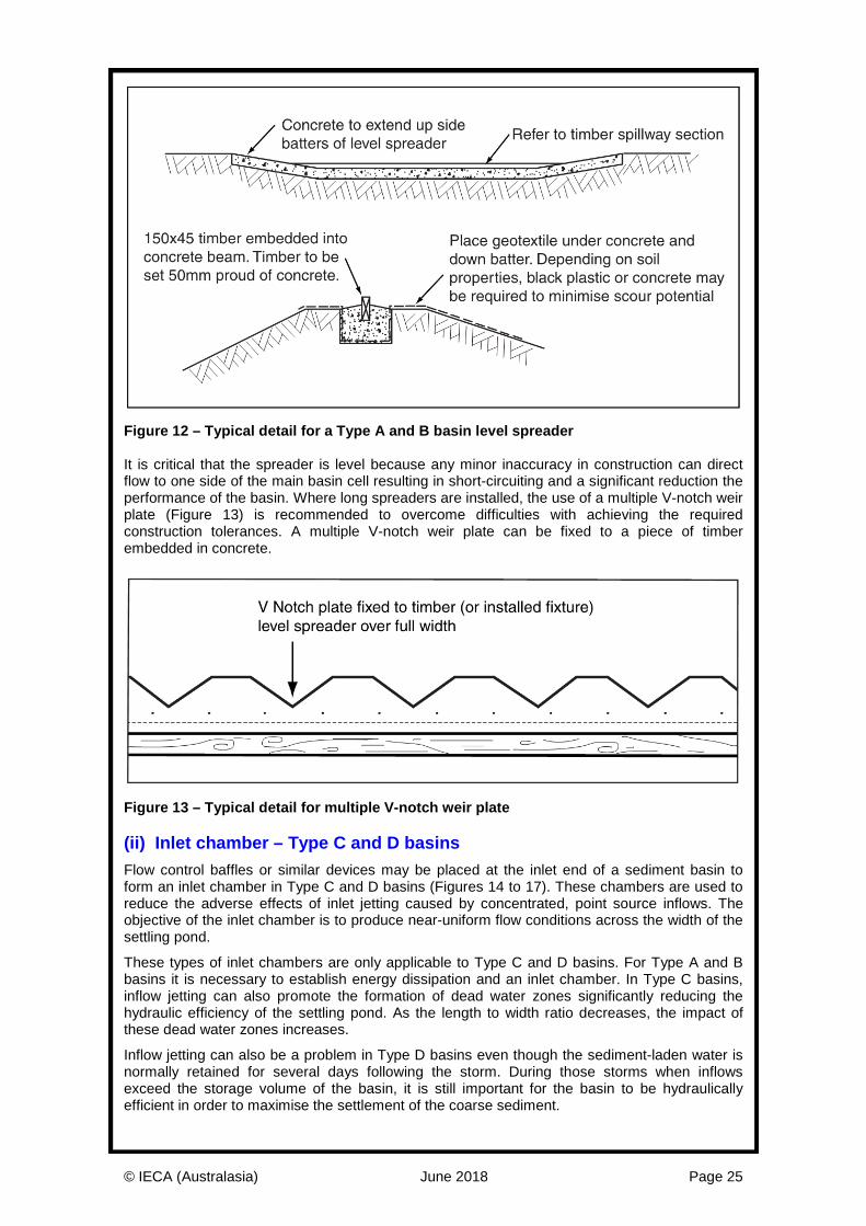
Figure 10 – Multiple inflows to a Type A or B basin
Figure 11 – Multiple inflows to a Type A or B basin The inlet chamber (or forebay) should be sized at approximately 10% of the size of the main basin cell, and have a minimum length of 5 m unless site constraints preclude this size. To avoid re-suspension of floc particles a minimum depth of 1.0 m is recommended. Where site constraints do not allow the construction of a forebay to the recommended dimensions, monitoring of the performance of the forebay should be undertaken to determine the requirement for any modifications. A critical component of the inlet chamber is to spread flow into the main basin cell to promote uniform flow to the outlet. To achieve uniform flow the construction of a level spreader is required. The level spreader can be constructed of a range of material including timber, concrete and aluminium. A typical detail of a level spreader is provided in Figure 12, however alternative approaches can be adopted as long as the design intent is achieved. Care is to be undertaken to minimise any potential for scour on the down-slope face of the level spreader. Protection of the soil surface will be required with concrete, geotextile, plastic or as dictated by the soil properties, slope of the batter face and flow velocity. The level spreader is to be constructed 100–200 mm above the emergency spillway level or as required to ensure the level spreader functions during high events and is not flooded due to water in the main basin cell.
© IECA (Australasia) June 2018 Page 25
Figure 12 – Typical detail for a Type A and B basin level spreader It is critical that the spreader is level because any minor inaccuracy in construction can direct flow to one side of the main basin cell resulting in short-circuiting and a significant reduction the performance of the basin. Where long spreaders are installed, the use of a multiple V-notch weir plate (Figure 13) is recommended to overcome difficulties with achieving the required construction tolerances. A multiple V-notch weir plate can be fixed to a piece of timber embedded in concrete.
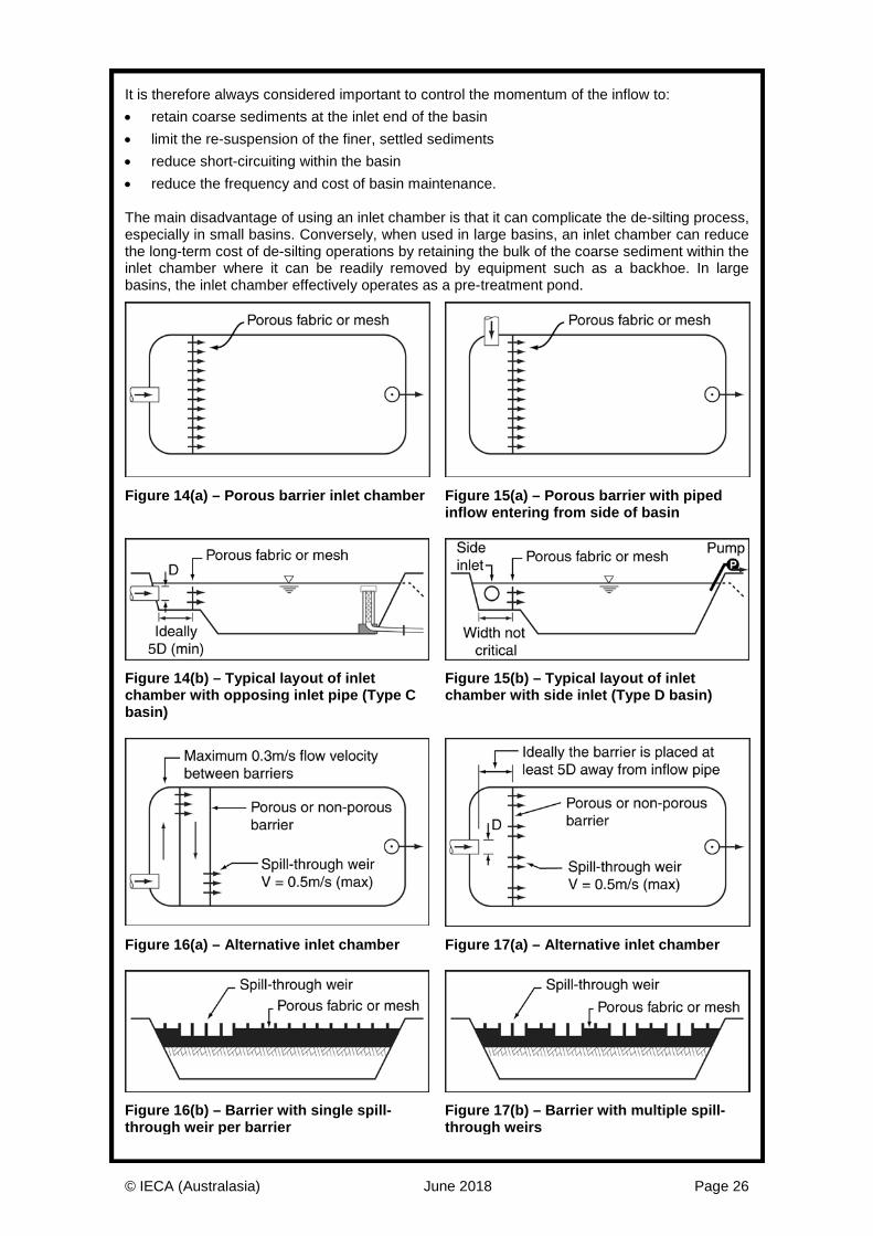
Figure 13 – Typical detail for multiple V-notch weir plate (ii) Inlet chamber – Type C and D basins Flow control baffles or similar devices may be placed at the inlet end of a sediment basin to form an inlet chamber in Type C and D basins (Figures 14 to 17). These chambers are used to reduce the adverse effects of inlet jetting caused by concentrated, point source inflows. The objective of the inlet chamber is to produce near-uniform flow conditions across the width of the settling pond.
These types of inlet chambers are only applicable to Type C and D basins. For Type A and B basins it is necessary to establish energy dissipation and an inlet chamber. In Type C basins, inflow jetting can also promote the formation of dead water zones significantly reducing the hydraulic efficiency of the settling pond. As the length to width ratio decreases, the impact of these dead water zones increases.
Inflow jetting can also be a problem in Type D basins even though the sediment-laden water is normally retained for several days following the storm. During those storms when inflows exceed the storage volume of the basin, it is still important for the basin to be hydraulically efficient in order to maximise the settlement of the coarse sediment.
© IECA (Australasia) June 2018 Page 26
It is therefore always considered important to control the momentum of the inflow to: • retain coarse sediments at the inlet end of the basin • limit the re-suspension of the finer, settled sediments • reduce short-circuiting within the basin • reduce the frequency and cost of basin maintenance. The main disadvantage of using an inlet chamber is that it can complicate the de-silting process, especially in small basins. Conversely, when used in large basins, an inlet chamber can reduce the long-term cost of de-silting operations by retaining the bulk of the coarse sediment within the inlet chamber where it can be readily removed by equipment such as a backhoe. In large basins, the inlet chamber effectively operates as a pre-treatment pond.
Figure 14(a) – Porous barrier inlet chamber Figure 15(a) – Porous barrier with piped
inflow entering from side of basin
Figure 14(b) – Typical layout of inlet chamber with opposing inlet pipe (Type C basin)
Figure 15(b) – Typical layout of inlet chamber with side inlet (Type D basin)
Figure 16(a) – Alternative inlet chamber Figure 17(a) – Alternative inlet chamber
Figure 16(b) – Barrier with single spill-through weir per barrier
Figure 17(b) – Barrier with multiple spill-through weirs
© IECA (Australasia) June 2018 Page 27
The use of an inlet chamber is usually governed by the need to adopt a low hydraulic efficiency correction factor (He). The incorporation of inlet baffles should be given serious consideration within Type C basins if the expected velocity of any concentrated inflows exceeds 1 m/s. Table 22 summaries the design of various inlet chambers. Table 22 – Design of various inlet chambers
Baffle type Description
Shade cloth An inlet chamber formed by staking coarse shade cloth across the full width of the settling pond. Typical spacing between support posts is 0.5 to 1.0 m depending on the expected hydraulic force on the fence.
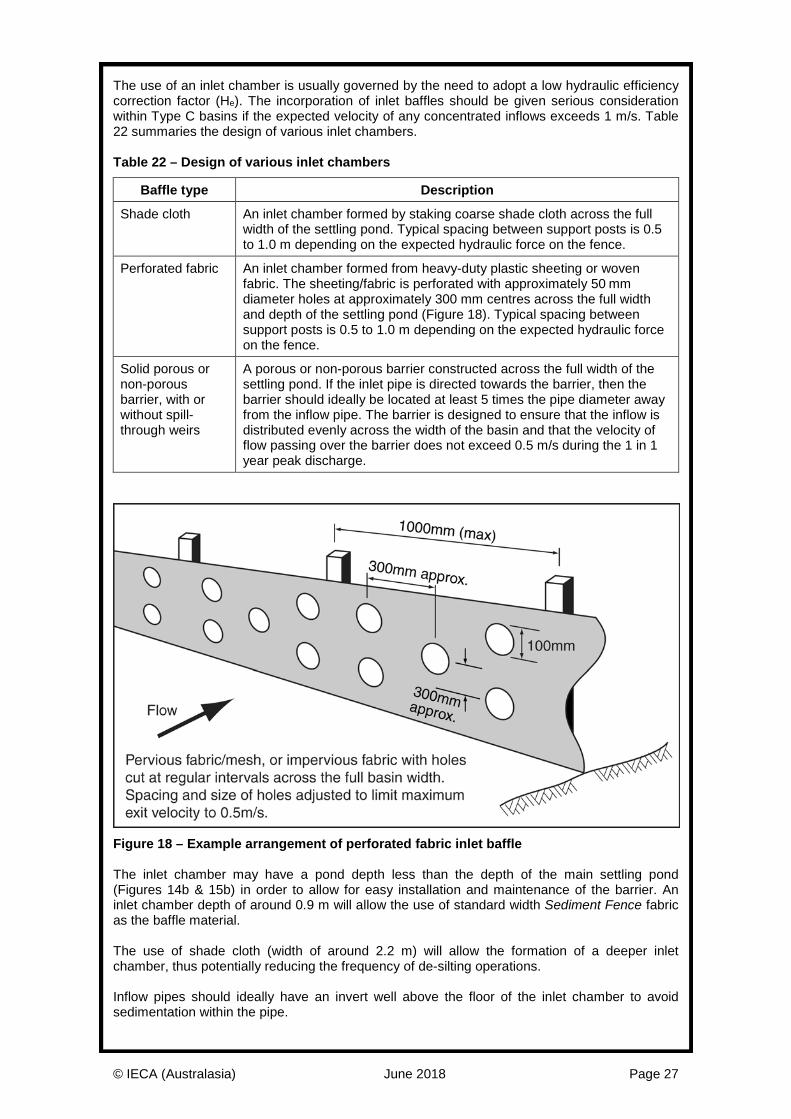
Perforated fabric An inlet chamber formed from heavy-duty plastic sheeting or woven fabric. The sheeting/fabric is perforated with approximately 50imm diameter holes at approximately 300 mm centres across the full width and depth of the settling pond (Figure 18). Typical spacing between support posts is 0.5 to 1.0 m depending on the expected hydraulic force on the fence.
Solid porous or non-porous barrier, with or without spill-through weirs
A porous or non-porous barrier constructed across the full width of the settling pond. If the inlet pipe is directed towards the barrier, then the barrier should ideally be located at least 5 times the pipe diameter away from the inflow pipe. The barrier is designed to ensure that the inflow is distributed evenly across the width of the basin and that the velocity of flow passing over the barrier does not exceed 0.5 m/s during the 1 in 1 year peak discharge.
Figure 18 – Example arrangement of perforated fabric inlet baffle The inlet chamber may have a pond depth less than the depth of the main settling pond (Figures 14b & 15b) in order to allow for easy installation and maintenance of the barrier. An inlet chamber depth of around 0.9 m will allow the use of standard width Sediment Fence fabric as the baffle material. The use of shade cloth (width of around 2.2 m) will allow the formation of a deeper inlet chamber, thus potentially reducing the frequency of de-silting operations. Inflow pipes should ideally have an invert well above the floor of the inlet chamber to avoid sedimentation within the pipe.
© IECA (Australasia) June 2018 Page 28
Step 10: Design the primary outlet system Historically, sediment basins were described as either ‘dry’ or ‘wet’ basins. This classification system can be seen as confusing because it refers only to the existence of an automatic draining system, and not to the option to retain water within the basin after storms so that the water can be used for on-site purposes. The traditional definition of wet and dry basins is provided below.
• Dry basins are free draining basins that fully de-water the settling zone after each storm. These usually include Type A and C basins.
• Wet basins are not free draining, but are designed to retain the stormwater runoff for extended periods in order to provide the basin with sufficient time for the gravitational settlement of fine sediment particles. These basins can include Type A, Type B, and Type D basins. Type A basins are included because the automatic decant system can be shut down if the basin’s discharge fails to meet the pre-determined water quality objectives.
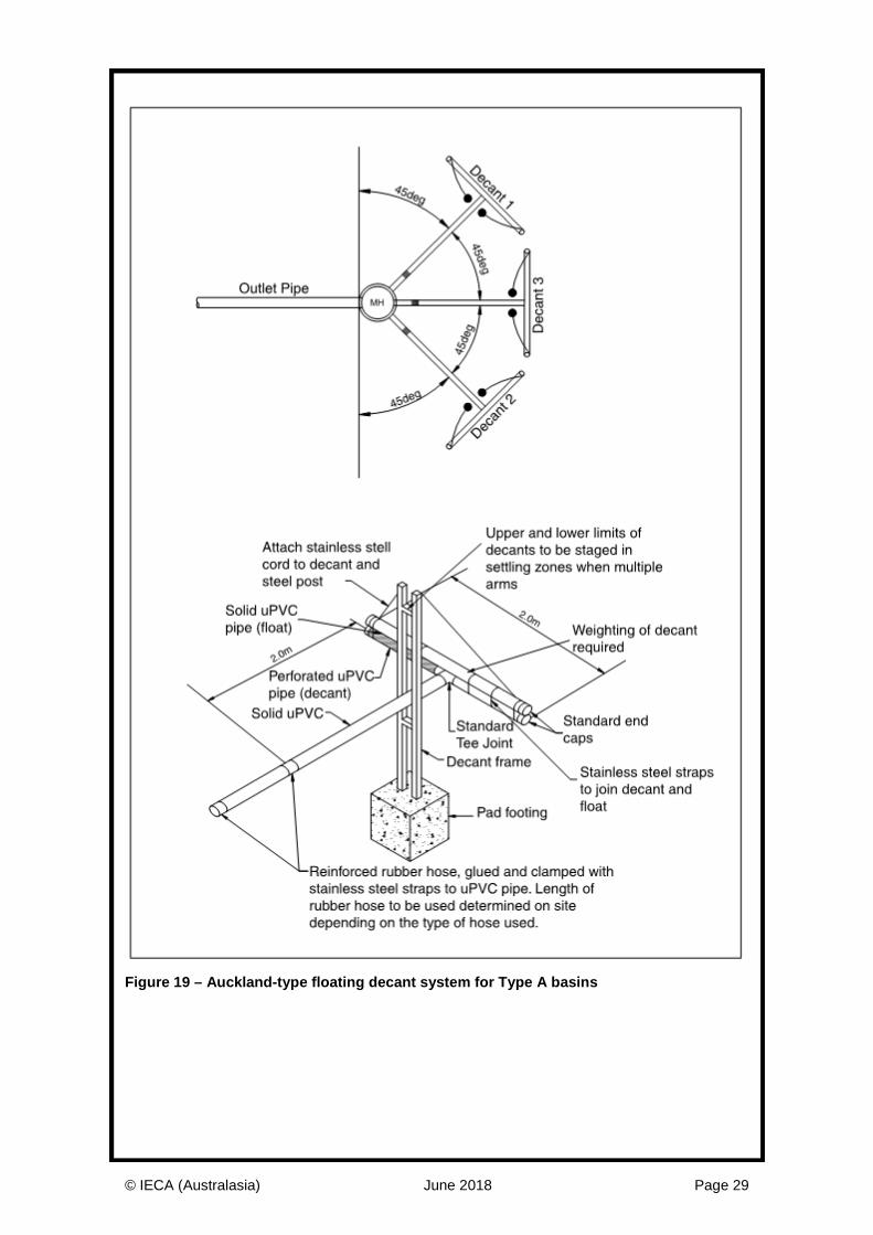
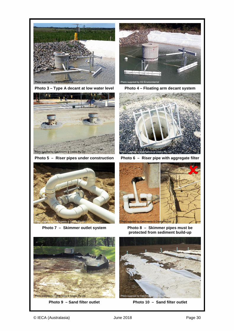
Type A basins require a floating low-flow decant system as described below. Type B basins may not require a formal decant system, other than that required to de-water the basin prior to the next storm, or to extract the water for usage on the site. Type C basins require a free-draining outlet system in the form of either a riser pipe outlet, or floating decant system. Gabion wall, Rock Filter Dam, and Sediment Weir outlet systems are not recommended unless a Type 2 sediment retention system has been specified. Type D basins usually require a pumped discharge system similar to Type B basins. If a piped outlet exists, then a flow control valve must be fitted to the outlet pipe to control the discharge. (i) Floating decant system for Type A basins Floating siphon outlet systems are designed to self-prime when the basin’s water exceeds a predetermined elevation. These systems decant the basin by siphoning water from the top of the pond, thus always extracting the cleanest water. This also extends the settlement period by commencing decant procedures only when the pond level reaches the predetermined elevation. Self-priming skimmer pipes are difficult to design and optimise. The Auckland-type, floating decant systems is depicted in Figure 19. This outlet system achieve 4.5 L/s per decant arm. Each decant arm has six rows of 10 mm diameter holes drilled at 60 mm spacings (totalling 200 holes) along the 2 m width of the decant arm. If larger flow rates are required, multiple decants structures are to be installed. Flow rates can be controlled through the sizing and number of holes in the decant, or by using an orifice plate based on appropriate hydraulic calculations. For small catchments, a single decant may be sufficient to achieve the required outflow rate. A single decant arm can connect directly into a pipe through the sediment basin wall negating the need for a manhole. Proprietary skimming systems are available and can be used as long as they adhere to the design intent, and will not draw up floc particles due to concentrated flow. (ii) Perforated riser pipe outlets (Type C basins) Key components of a perforated riser pipe outlet are listed below: • Anti-flotation mass = 110% of the displaced water mass. • Combined trash rack and anti-vortex screen placed on top of open riser pipe. • Minimum outlet pipe size of 250 mm. • Anti-seep collars (minimum of 1) placed on the buried outlet pipe. • Designed to drain the basin’s full settling zone volume in not less than 24 hours (to allow
adequate settlement time). Other types of outlet systems are described in Appendix B of Book 2 (IECA, 2008).
© IECA (Australasia) June 2018 Page 29
Figure 19 – Auckland-type floating decant system for Type A basins
© IECA (Australasia) June 2018 Page 30
Photo 3 – Type A decant at low water level Photo 4 – Floating arm decant system
Photo 5 – Riser pipes under construction Photo 6 – Riser pipe with aggregate filter
Photo 7 – Skimmer outlet system Photo 8 – Skimmer pipes must be
protected from sediment build-up
Photo 9 – Sand filter outlet Photo 10 – Sand filter outlet

© IECA (Australasia) June 2018 Page 31
Step 11: Design the emergency spillway The minimum design storm for sizing the emergency spillway is defined in Table 23. Table 23 – Recommended design standard for emergency spillways [1]
Design life Minimum design storm ARI
Less than 3 months operation 1 in 10 year
3 to 12 months operation 1 in 20 year
Greater than 12 months 1 in 50 year
If failure is expected to result in loss of life Probable Maximum Flood (PMF)
[1] Alternative design requirements may apply to Referable Dams in accordance with state legislation, or as recommended by the Dam Safety Committee (ANCOLD).
The crest of the emergency spillway is to be at least: • 300 mm above the primary outlet (if included) • 300 mm below a basin embankment formed in virgin soil • 450 mm below a basin embankment formed from fill. Recommended freeboard down the spillway chute is 300 mm. In addition to the above, design of the emergency spillway must ensure that the maximum water level within the basin during the design storm specified in Table 23 is at least: • 300 mm below a basin embankment formed from fill • 150 mm plus expected wave height for large basins with significant fetch length (note;
significant wind-generated waves can form on the surface of large basins). The approach channel can be curved upstream of the spillway crest, but must be straight from the crest to the energy dissipater. The approach channel should have a back-slope towards the impoundment area of not less than 2% and should be flared at its entrance, gradually reducing to the design width at the spillway crest. All reasonable and practicable efforts must be taken to construct the spillway in virgin soil, rather than within a fill embankment. Placement of an emergency spillway within a fill embankment can significantly increase the risk of failure. Anticipated wave heights may be determined from the procedures presented in the Shore Protection Manual (Department of the Army, 1984). The hydraulic design of sediment basin spillways is outlined in Section A5.4 of Appendix A – Construction Site Hydrology and Hydraulics (IECA, 2008). The downstream face of the spillway chute may be protected with concrete, rock, rock mattresses, or other suitable material as required for the expected maximum flow velocity. Grass-lined spillway chutes are generally not recommended for sediment basins due to their long establishment time and relatively low scour velocity. Care needs to be taken to ensure that flow passing through voids of the crest of a rock or rock mattress spillway does not significantly reduce the basin’s peak water level, or cause water to discharge down the spillway before reaching the nominated spillway crest elevation. Unlike permanent stormwater treatment ponds and wetlands, construction site sediment basins are not designed to allow high flows to bypass the basin. Even if the basin is hydraulically full, sediment-laden stormwater runoff should continue to be directed through the basin. This allows the continued settlement of coarse-grained particles contained in the flow. Thus a side-flow channel does not need to be constructed to bypass high flow directly to the spillway.
© IECA (Australasia) June 2018 Page 32
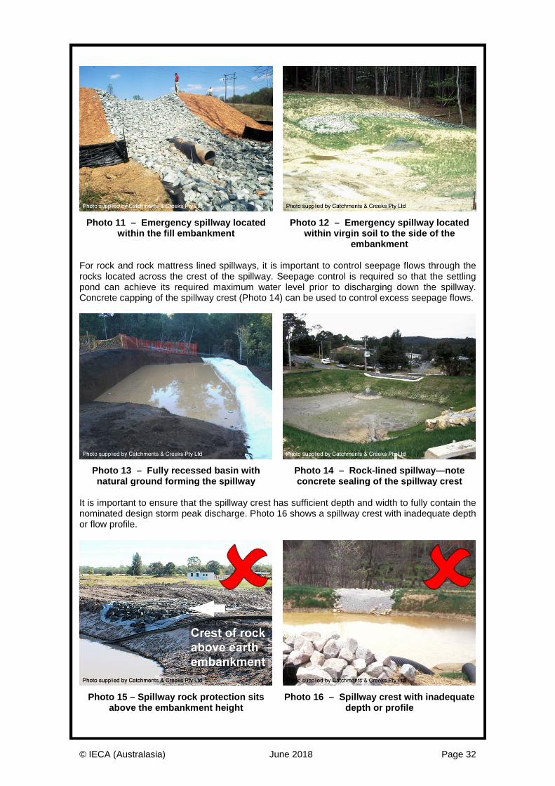
Photo 11 – Emergency spillway located
within the fill embankment Photo 12 – Emergency spillway located
within virgin soil to the side of the embankment
For rock and rock mattress lined spillways, it is important to control seepage flows through the rocks located across the crest of the spillway. Seepage control is required so that the settling pond can achieve its required maximum water level prior to discharging down the spillway. Concrete capping of the spillway crest (Photo 14) can be used to control excess seepage flows.
Photo 13 – Fully recessed basin with natural ground forming the spillway
Photo 14 – Rock-lined spillway—note concrete sealing of the spillway crest
It is important to ensure that the spillway crest has sufficient depth and width to fully contain the nominated design storm peak discharge. Photo 16 shows a spillway crest with inadequate depth or flow profile.
Photo 15 – Spillway rock protection sits
above the embankment height Photo 16 – Spillway crest with inadequate
depth or profile

© IECA (Australasia) June 2018 Page 33
Spillway design features
Hydraulic design • Basin spillways are hydraulic structures
that need to be designed for a specified design storm using standard hydraulic equations.
• The hydraulic design can be broken down into three components: − design of the spillway inlet using an
appropriate weir equation − sizing rock for the face of the spillway
based on Manning’s equation velocity − sizing rock for the spillway outlet.
Figure 20 – Basin spillway hydraulics
Design of spillway crest • Flow conditions at the spillway crest may
be determined using an appropriate weir equation.
• It is important to ensure that the maximum potential water level within the dam at peak discharge will be fully contained by the basin’s embankments.
• The sealing of the spillway crest is necessary to maximise basin storage and prevent leakage through the rock voids.
Figure 21 – Sealing of spillway crest
Design of spillway chute • Determination of rock size on the spillway
is based on either the maximum unit flow rate (q) or the maximum flow velocity (v) down the spillway.
• The upstream segment of the spillway’s inflow channel can be curved (i.e. that section upstream of the spillway crest).
• Once the spillway descends down the embankment (i.e. where the flow is supercritical) the spillway must be straight.
Figure 22 – Spillway cut into virgin soil
Design of energy dissipater • A suitable energy dissipater or outlet
structure is required at the base of the spillway.
• The design of the energy dissipater must be assessed on a case-by-case basis.
• It may or may not always be appropriate to use the standard rock sizing design charts presented elsewhere in this document.
• The photo (left) shows a ‘wet’ dissipation pond, which is not typical for construction sites.
Photo 17 – Energy dissipation pond
© IECA (Australasia) June 2018 Page 34
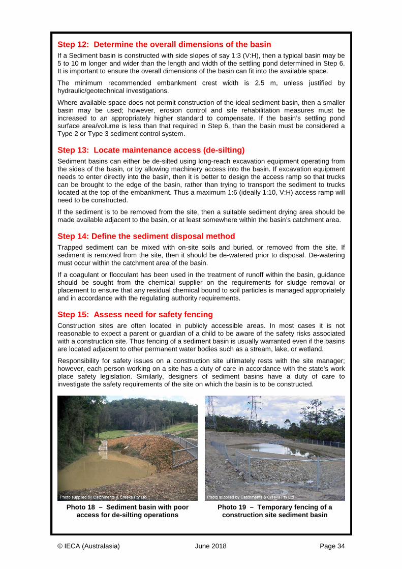
Step 12: Determine the overall dimensions of the basin If a Sediment basin is constructed with side slopes of say 1:3 (V:H), then a typical basin may be 5 to 10 m longer and wider than the length and width of the settling pond determined in Step 6. It is important to ensure the overall dimensions of the basin can fit into the available space.
The minimum recommended embankment crest width is 2.5 m, unless justified by hydraulic/geotechnical investigations.
Where available space does not permit construction of the ideal sediment basin, then a smaller basin may be used; however, erosion control and site rehabilitation measures must be increased to an appropriately higher standard to compensate. If the basin’s settling pond surface area/volume is less than that required in Step 6, than the basin must be considered a Type 2 or Type 3 sediment control system. Step 13: Locate maintenance access (de-silting) Sediment basins can either be de-silted using long-reach excavation equipment operating from the sides of the basin, or by allowing machinery access into the basin. If excavation equipment needs to enter directly into the basin, then it is better to design the access ramp so that trucks can be brought to the edge of the basin, rather than trying to transport the sediment to trucks located at the top of the embankment. Thus a maximum 1:6 (ideally 1:10, V:H) access ramp will need to be constructed.
If the sediment is to be removed from the site, then a suitable sediment drying area should be made available adjacent to the basin, or at least somewhere within the basin’s catchment area. Step 14: Define the sediment disposal method Trapped sediment can be mixed with on-site soils and buried, or removed from the site. If sediment is removed from the site, then it should be de-watered prior to disposal. De-watering must occur within the catchment area of the basin.
If a coagulant or flocculant has been used in the treatment of runoff within the basin, guidance should be sought from the chemical supplier on the requirements for sludge removal or placement to ensure that any residual chemical bound to soil particles is managed appropriately and in accordance with the regulating authority requirements. Step 15: Assess need for safety fencing Construction sites are often located in publicly accessible areas. In most cases it is not reasonable to expect a parent or guardian of a child to be aware of the safety risks associated with a construction site. Thus fencing of a sediment basin is usually warranted even if the basins are located adjacent to other permanent water bodies such as a stream, lake, or wetland.
Responsibility for safety issues on a construction site ultimately rests with the site manager; however, each person working on a site has a duty of care in accordance with the state’s work place safety legislation. Similarly, designers of sediment basins have a duty of care to investigate the safety requirements of the site on which the basin is to be constructed.
Photo 18 – Sediment basin with poor
access for de-silting operations Photo 19 – Temporary fencing of a
construction site sediment basin
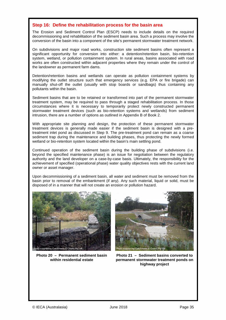
© IECA (Australasia) June 2018 Page 35
Step 16: Define the rehabilitation process for the basin area The Erosion and Sediment Control Plan (ESCP) needs to include details on the required decommissioning and rehabilitation of the sediment basin area. Such a process may involve the conversion of the basin into a component of the site’s permanent stormwater treatment network. On subdivisions and major road works, construction site sediment basins often represent a significant opportunity for conversion into either: a detention/retention basin, bio-retention system, wetland, or pollution containment system. In rural areas, basins associated with road works are often constructed within adjacent properties where they remain under the control of the landowner as permanent farm dams. Detention/retention basins and wetlands can operate as pollution containment systems by modifying the outlet structure such that emergency services (e.g. EPA or fire brigade) can manually shut-off the outlet (usually with stop boards or sandbags) thus containing any pollutants within the basin. Sediment basins that are to be retained or transformed into part of the permanent stormwater treatment system, may be required to pass through a staged rehabilitation process. In those circumstances where it is necessary to temporarily protect newly constructed permanent stormwater treatment devices (such as bio-retention systems and wetlands) from sediment intrusion, there are a number of options as outlined in Appendix B of Book 2. With appropriate site planning and design, the protection of these permanent stormwater treatment devices is generally made easier if the sediment basin is designed with a pre-treatment inlet pond as discussed in Step 9. The pre-treatment pond can remain as a coarse sediment trap during the maintenance and building phases, thus protecting the newly formed wetland or bio-retention system located within the basin’s main settling pond. Continued operation of the sediment basin during the building phase of subdivisions (i.e. beyond the specified maintenance phase) is an issue for negotiation between the regulatory authority and the land developer on a case-by-case basis. Ultimately, the responsibility for the achievement of specified (operational phase) water quality objectives rests with the current land owner or asset manager. Upon decommissioning of a sediment basin, all water and sediment must be removed from the basin prior to removal of the embankment (if any). Any such material, liquid or solid, must be disposed of in a manner that will not create an erosion or pollution hazard.
Photo 20 – Permanent sediment basin
within residential estate Photo 21 – Sediment basins converted to permanent stormwater treatment ponds on
highway project
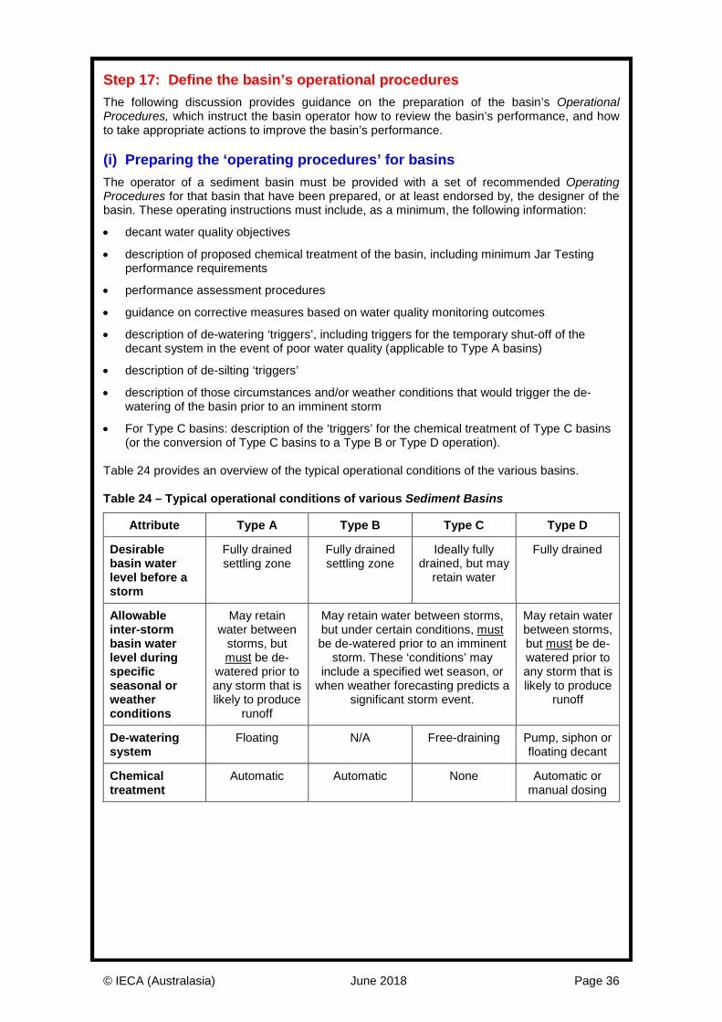
© IECA (Australasia) June 2018 Page 36
Step 17: Define the basin’s operational procedures The following discussion provides guidance on the preparation of the basin’s Operational Procedures, which instruct the basin operator how to review the basin’s performance, and how to take appropriate actions to improve the basin’s performance. (i) Preparing the ‘operating procedures’ for basins The operator of a sediment basin must be provided with a set of recommended Operating Procedures for that basin that have been prepared, or at least endorsed by, the designer of the basin. These operating instructions must include, as a minimum, the following information:
• decant water quality objectives
• description of proposed chemical treatment of the basin, including minimum Jar Testing performance requirements
• performance assessment procedures
• guidance on corrective measures based on water quality monitoring outcomes
• description of de-watering ‘triggers’, including triggers for the temporary shut-off of the decant system in the event of poor water quality (applicable to Type A basins)
• description of de-silting ‘triggers’
• description of those circumstances and/or weather conditions that would trigger the de-watering of the basin prior to an imminent storm
• For Type C basins: description of the ‘triggers’ for the chemical treatment of Type C basins (or the conversion of Type C basins to a Type B or Type D operation).
Table 24 provides an overview of the typical operational conditions of the various basins. Table 24 – Typical operational conditions of various Sediment Basins
Attribute Type A Type B Type C Type D
Desirable basin water level before a storm
Fully drained settling zone
Fully drained settling zone
Ideally fully drained, but may
retain water
Fully drained
Allowable inter-storm basin water level during specific seasonal or weather conditions
May retain water between
storms, but must be de-
watered prior to any storm that is likely to produce
runoff
May retain water between storms, but under certain conditions, must be de-watered prior to an imminent
storm. These ‘conditions’ may include a specified wet season, or
when weather forecasting predicts a significant storm event.
May retain water between storms, but must be de-watered prior to any storm that is likely to produce
runoff
De-watering system
Floating N/A Free-draining Pump, siphon or floating decant
Chemical treatment
Automatic Automatic None Automatic or manual dosing
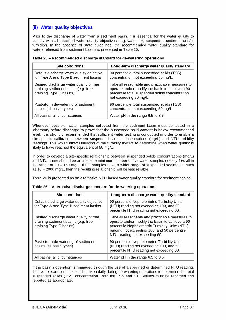
© IECA (Australasia) June 2018 Page 37
(ii) Water quality objectives Prior to the discharge of water from a sediment basin, it is essential for the water quality to comply with all specified water quality objectives (e.g. water pH, suspended sediment and/or turbidity). In the absence of state guidelines, the recommended water quality standard for waters released from sediment basins is presented in Table 25. Table 25 – Recommended discharge standard for de-watering operations
Site conditions Long-term discharge water quality standard
Default discharge water quality objective for Type A and Type B sediment basins
90 percentile total suspended solids (TSS) concentration not exceeding 50 mg/L.
Desired discharge water quality of free draining sediment basins (e.g. free draining Type C basins)
Take all reasonable and practicable measures to operate and/or modify the basin to achieve a 90 percentile total suspended solids concentration not exceeding 50 mg/L.
Post-storm de-watering of sediment basins (all basin types)
90 percentile total suspended solids (TSS) concentration not exceeding 50 mg/L.
All basins, all circumstances Water pH in the range 6.5 to 8.5 Whenever possible, water samples collected from the sediment basin must be tested in a laboratory before discharge to prove that the suspended solid content is below recommended level. It is strongly recommended that sufficient water testing is conducted in order to enable a site-specific calibration between suspended solids concentrations (mg/L) and NTU turbidity readings. This would allow utilisation of the turbidity meters to determine when water quality is likely to have reached the equivalent of 50 mg/L. In order to develop a site-specific relationship between suspended solids concentrations (mg/L) and NTU, there should be an absolute minimum number of five water samples (ideally 9+), all in the range of 20 – 150 mg/L. If the samples have a wider range of suspended sediments, such as 10 – 2000 mg/L, then the resulting relationship will be less reliable. Table 26 is presented as an alternative NTU-based water quality standard for sediment basins. Table 26 – Alternative discharge standard for de-watering operations
Site conditions Long-term discharge water quality standard
Default discharge water quality objective for Type A and Type B sediment basins
90 percentile Nephelometric Turbidity Units (NTU) reading not exceeding 100, and 50 percentile NTU reading not exceeding 60.
Desired discharge water quality of free draining sediment basins (e.g. free draining Type C basins)
Take all reasonable and practicable measures to operate and/or modify the basin to achieve a 90 percentile Nephelometric Turbidity Units (NTU) reading not exceeding 100, and 50 percentile NTU reading not exceeding 60.
Post-storm de-watering of sediment basins (all basin types)
90 percentile Nephelometric Turbidity Units (NTU) reading not exceeding 100, and 50 percentile NTU reading not exceeding 60.
All basins, all circumstances Water pH in the range 6.5 to 8.5 If the basin’s operation is managed through the use of a specified or determined NTU reading, then water samples must still be taken daily during de-watering operations to determine the total suspended solids (TSS) concentration. Both the TSS and NTU values must be recorded and reported as appropriate.
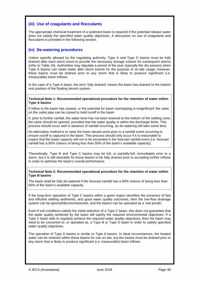
© IECA (Australasia) June 2018 Page 38
(iii) Use of coagulants and flocculants The appropriate chemical treatment of a sediment basin is required if the potential release water does not satisfy the specified water quality objectives. A discussion on use of coagulants and flocculants is provided in the following section.
(iv) De-watering procedures Unless specific allowed by the regulating authority, Type A and Type D basins must be fully drained after each storm event to provide the necessary storage volume for subsequent storms (refer to Table 24). Authorities may stipulate a period of the year (typically the dry season) when Type A basins can retain water after storm events for the purpose of on-site usage; however, these basins must be drained prior to any storm that is likely to produce significant (i.e. measurable) basin inflows. In the case of a Type A basin, the term ‘fully drained’ means the basin has drained to the bottom rest position of the floating decent system.
Technical Note 1: Recommended operational procedure for the retention of water within Type A basins If inflow to the basin has ceased, or the potential for basin overtopping is insignificant’ the valve on the outlet pipe can be closed to hold runoff in the basin
If, prior to further rainfall, the water level has not been lowered to the bottom of the settling zone, the valve should be opened, provided that the water quality is within the discharge limits. This process should occur well in advance of rainfall occurring, as de-watering will take some time.
An alternative method is to raise the lower decant arms prior to a rainfall event occurring to ensure runoff is captured in the basin. This process should only occur if it is reasonable to expect that the basin capacity will not to be exceeded in the forecast rainfall event (i.e. forecast rainfall has a 90% chance of being less than 50% of the basin’s available capacity).
Theoretically, Type B and Type C basins may be full, or partially-full, immediately prior to a storm, but it is still desirable for these basins to be fully drained prior to accepting further inflows in order to optimise the basin’s overall performance.
Technical Note 2: Recommended operational procedure for the retention of water within Type B basins The basin shall be fully de-watered if the forecast rainfall has a 90% chance of being less than 50% of the basin’s available capacity.
If the long-term operation of Type C basins within a given region identifies the presence of fast and efficient settling sediments, and good water quality outcomes, then the low-flow drainage system can be ignored/decommissioned, and the basins can be operated as a ‘wet ponds’. Even if soil conditions satisfy the initial selection of a Type C basin, this does not guarantee that the water quality achieved by the basin will satisfy the required environmental objectives. If a Type C basin fails to regularly achieve the required water quality objectives, then the basin may need to be converted to, or operated as, a Type B or Type D basin in order to satisfy specified water quality objectives. The operation of Type D basins is similar to Type A basins. In ideal circumstances, the treated water can be retained within these basins for use on site, but the basins must be drained prior to any storm that is likely to produce significant (i.e. measurable) basin inflows.
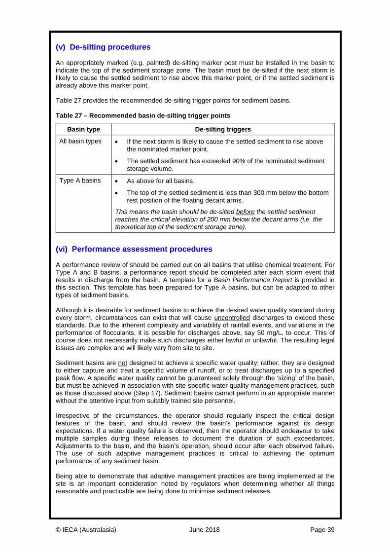
© IECA (Australasia) June 2018 Page 39
(v) De-silting procedures An appropriately marked (e.g. painted) de-silting marker post must be installed in the basin to indicate the top of the sediment storage zone. The basin must be de-silted if the next storm is likely to cause the settled sediment to rise above this marker point, or if the settled sediment is already above this marker point. Table 27 provides the recommended de-silting trigger points for sediment basins. Table 27 – Recommended basin de-silting trigger points
Basin type De-silting triggers
All basin types • If the next storm is likely to cause the settled sediment to rise above the nominated marker point.
• The settled sediment has exceeded 90% of the nominated sediment storage volume.
Type A basins • As above for all basins.
• The top of the settled sediment is less than 300 mm below the bottom rest position of the floating decant arms.
This means the basin should be de-silted before the settled sediment reaches the critical elevation of 200 mm below the decant arms (i.e. the theoretical top of the sediment storage zone).
(vi) Performance assessment procedures A performance review of should be carried out on all basins that utilise chemical treatment. For Type A and B basins, a performance report should be completed after each storm event that results in discharge from the basin. A template for a Basin Performance Report is provided in this section. This template has been prepared for Type A basins, but can be adapted to other types of sediment basins. Although it is desirable for sediment basins to achieve the desired water quality standard during every storm, circumstances can exist that will cause uncontrolled discharges to exceed these standards. Due to the inherent complexity and variability of rainfall events, and variations in the performance of flocculants, it is possible for discharges above, say 50 mg/L, to occur. This of course does not necessarily make such discharges either lawful or unlawful. The resulting legal issues are complex and will likely vary from site to site. Sediment basins are not designed to achieve a specific water quality; rather, they are designed to either capture and treat a specific volume of runoff, or to treat discharges up to a specified peak flow. A specific water quality cannot be guaranteed solely through the ‘sizing’ of the basin, but must be achieved in association with site-specific water quality management practices, such as those discussed above (Step 17). Sediment basins cannot perform in an appropriate manner without the attentive input from suitably trained site personnel. Irrespective of the circumstances, the operator should regularly inspect the critical design features of the basin, and should review the basin’s performance against its design expectations. If a water quality failure is observed, then the operator should endeavour to take multiple samples during these releases to document the duration of such exceedances. Adjustments to the basin, and the basin’s operation, should occur after each observed failure. The use of such adaptive management practices is critical to achieving the optimum performance of any sediment basin. Being able to demonstrate that adaptive management practices are being implemented at the site is an important consideration noted by regulators when determining whether all things reasonable and practicable are being done to minimise sediment releases.
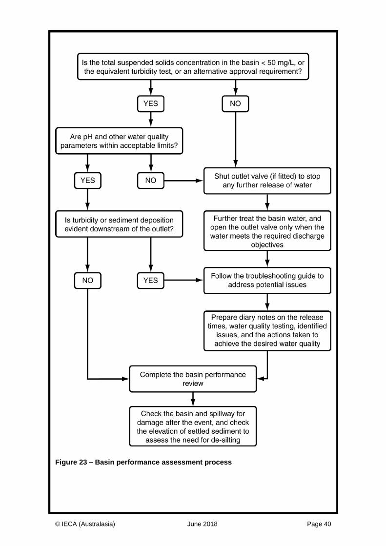
© IECA (Australasia) June 2018 Page 40
Figure 23 – Basin performance assessment process
© IECA (Australasia) June 2018 Page 41
Coagulants and flocculants The following is a brief discussion on the use of coagulants and flocculants to enhance the settling characteristics of sediment-laden water. Readers should refer to the associated Book 4 design fact sheet – Chemical coagulants and flocculants for the latest technical information on the testing, selection and use of these products. (i) Coagulation A coagulant is utilised to neutralise or destabilise the charge on clay or colloidal particles. Most clay particles in water are negatively charged and therefore any positive ion (cation) can be used as a coagulant. Charge neutralisation in water can occur very rapidly; therefore, mixing is important for effective treatment of turbid water. After a short time, the ions form hydroxide gels which trap particles, or bridge between particles creating a floc that may settle. There is always the possibility of overdosing with coagulants and building up excess positive charge, hence complying within the optimum dosage range is critical. When a cationic coagulant is overdosed, the clay and colloidal particles will take on a positive charge and repel each other and limit any settling. The dosage range of a coagulant will vary depending on site water chemistry. Different coagulants also have an optimum pH range over which they are effective and pH buffering may be required depending on the coagulant and water chemistry. The flocs generated by coagulation are generally small and compact. They can also be broken down under high velocity or high shear conditions. (ii) Flocculation Flocculation is a process of contact and adhesion whereby the particles of a dispersion form larger-size clusters. Flocculation can occur through the use of a coagulant, flocculant, or both. Coagulants achieve flocculation through charge neutralisation where as flocculants physically bind clay and colloidal particles together. The use of natural and synthetic polymeric flocculants can be used to generate larger more stable flocs and may reduce treatment times. This is achieved by bringing dispersed particles together increasing the effective particle size. Flocculants can be used alone, or in combination with coagulants. (iii) Ecotoxicity The by-products of coagulants and flocculants can, in certain circumstances, become toxic to aquatic life. A high or low water pH is often the trigger for the release of these materials in a toxic form. It is generally accepted that dissolved aluminium at a concentration between 0.050 and 0.100 mg/L and a pH between 6.5 and 8.0 presents little threat of toxicity. However, at lower pH, the toxicity increases with an effect of possible major concern being the coagulation of mucus on the gills of fish. There is limited published data on the aquatic ecotoxicity of calcium based coagulants such as calcium sulphate and calcium chloride. Designers of chemical treatment systems must always seek the latest advice on the potential impacts of coagulants and flocculants on receiving waters, and must have an adequate understanding of the types of receiving water associated with any sediment basin design. Ecotoxicity information has been adopted from the Auckland Regional Council TP226 and TP227 documents. Chemical specific ecotoxicity information should be sought from chemical suppliers in accordance with the regulating authority’s requirements.
© IECA (Australasia) June 2018 Page 42
(iv) Jar testing The purpose of jar testing is to select appropriate coagulants and/or flocculants along with determining their optimum dose rates. The recommended testing procedure is described below. Jar tests are conducted on a four or six-place gang stirrer. Jars (beakers) with different treatment programs or the same product at different dosages are run side-by-side, and the results compared to an untreated beaker. Where access to a laboratory is not practicable field tests can be undertaken following a similar process to that described in the procedure with stirring and settling timeframes in multiple beakers. Testing should be undertaken by a suitably qualified person in the use of coagulants and flocculants. Preference is given to the use of raw water collected on site which is representative of runoff (including water temperature, which affect settlement characteristics) during the life cycle of the sediment basin. Where raw water is not available representative soil from the site is to be mixed with water to create indicative runoff water chemistry. To create a water sample from soil, a recommended procedure is provided below. Soil / water solution procedure: Step 1. Obtain a soil sample from representative soils to be exposed during the life cycle of
the sediment basin. Where multiple soil types are likely to be encountered within the life cycle of the basin, jar tests should be undertaken for the range of soil types.
Step 2. Crush the soil (if dry) and shake through a 2 mm sieve to remove any coarse material.
Step 3. Place approximately 100 grams of soil into 10 litres of water. Ensure the water has the same temperature as the expected water temperature within the sediment basin during the settling phase.
Step 4. Stir rapidly until soil particles are suspended.
Step 5. Leave solution for 10 minutes.
Step 6. Stir rapidly to resuspend any settled material.
Step 7. Decant into beakers for jar testing. Jar testing procedure: Step 1. Fill the appropriate number of (matched) 1000 mL transparent beakers with well-
mixed test water, using a 1000 mL graduate. Record starting pH, temperature and turbidity.
Step 2. Place the filled beakers on the gang stirrer, with the paddles positioned identically in each beaker.
Step 3. Mix the beakers at 40–50 rpm for 30 seconds. Discontinue mixing until coagulant or flocculant addition is completed.
Step 4. Leave the first beaker as a control, and add increasing dosages of the first coagulant/flocculant to subsequent beakers. Inject coagulant/ flocculant solutions as quickly as possible, below the liquid level and about halfway between the stirrer shaft and beaker wall.
Step 5. Increase the mixing speed to 100–125 rpm for 15–30 seconds (rapid mix).
Step 6. Reduce the mixing to 40 rpm and continue the slow mix for up to 5 minutes.
Step 7. Turn the mixer off and allow settling to occur.
Step 8. After settling for a period of time, note clarity and record on Floc Performance Report. Record pH and turbidity.
Step 9. Remove the jars from the gang stirrer, empty the contents and thoroughly clean the beakers.
Step 10. Repeat the procedure as required for different chemicals, dose rates or soil/water mixtures.
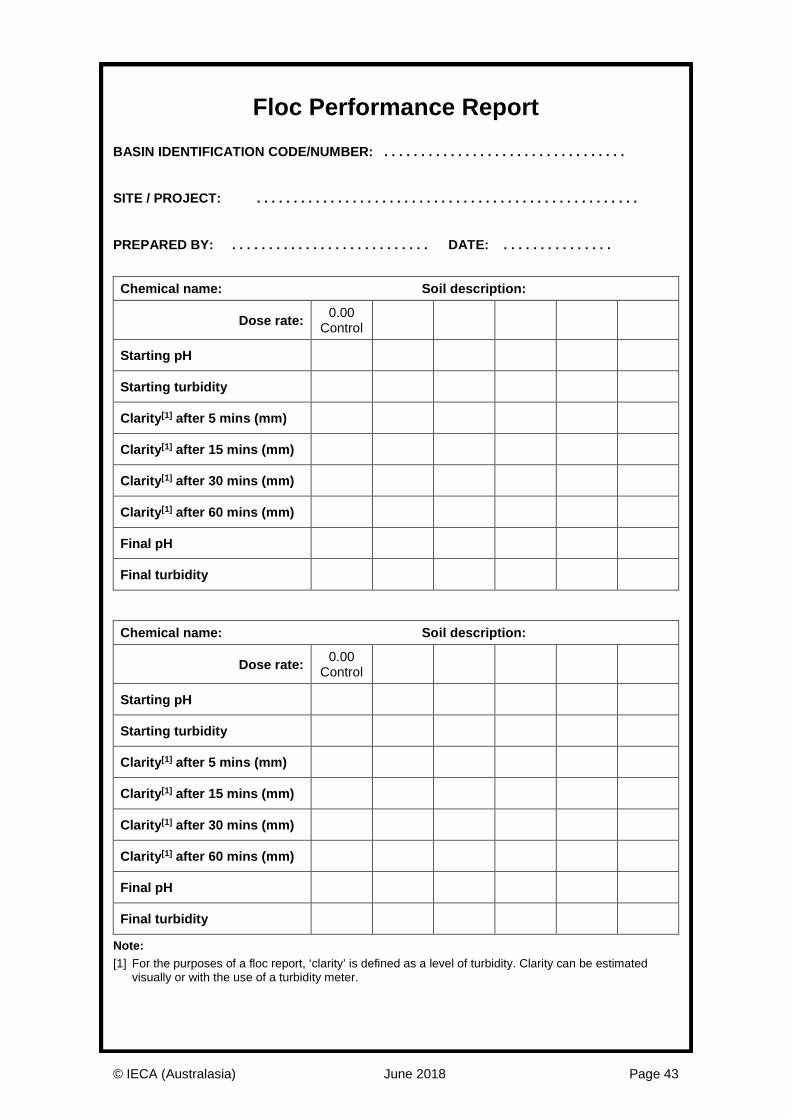
© IECA (Australasia) June 2018 Page 43
Floc Performance Report BASIN IDENTIFICATION CODE/NUMBER: . . . . . . . . . . . . . . . . . . . . . . . . . . . . . . . . . SITE / PROJECT: . . . . . . . . . . . . . . . . . . . . . . . . . . . . . . . . . . . . . . . . . . . . . . . . . . . . PREPARED BY: . . . . . . . . . . . . . . . . . . . . . . . . . . . DATE: . . . . . . . . . . . . . . .
Chemical name: Soil description:
Dose rate: 0.00 Control
Starting pH
Starting turbidity
Clarity[1] after 5 mins (mm)
Clarity[1] after 15 mins (mm)
Clarity[1] after 30 mins (mm)
Clarity[1] after 60 mins (mm)
Final pH
Final turbidity
Chemical name: Soil description:
Dose rate: 0.00 Control
Starting pH
Starting turbidity
Clarity[1] after 5 mins (mm)
Clarity[1] after 15 mins (mm)
Clarity[1] after 30 mins (mm)
Clarity[1] after 60 mins (mm)
Final pH
Final turbidity
Note: [1] For the purposes of a floc report, ‘clarity’ is defined as a level of turbidity. Clarity can be estimated
visually or with the use of a turbidity meter.
![Assessment of Agricultural Best Management Practices Using ... · Crop rotation; Terrace; Sediment basin Pipiripau River basin, Brazil, 235 km2 SWAT Sediment [31] Nutrient management;](https://img.pdfslide.net/doc/110x75/5f4699bbcbbe3c56dd29a372/assessment-of-agricultural-best-management-practices-using-crop-rotation-terrace.jpg)