Embed Size (px)
Citation preview
See discussions, stats, and author profiles for this publication at: https://www.researchgate.net/publication/273063247
Sediment bypass tunnel design - review and outlook
Chapter · June 2011
CITATIONS
12
2 authors:
Some of the authors of this publication are also working on these related projects:
Sediment Bypass Systems View project
Design optimization of alpine desanding facilities View project
Christian Auel
ILF Consulting Engineers, Innsbruck, Austria
26 PUBLICATIONS 111 CITATIONS
SEE PROFILE
Robert Michael Boes
ETH Zurich
96 PUBLICATIONS 631 CITATIONS
SEE PROFILE
All content following this page was uploaded by Christian Auel on 22 April 2015.
The user has requested enhancement of the downloaded file.

403
1 INTRODUCTION
Reservoir sedimentation is an increasing problem affecting the majority of reservoirs not only in Switzerland but worldwide. As many dams are more than 50 years of age, this problem is be-coming more and more serious nowadays. Mean annual sedimentation rates of 0.2 to 2% of the reservoir volume led, and will lead in the very next future, to high aggradation (Schleiss & Oehy 2002, Sumi et al. 2004, Basson 2009, Schleiss et al. 2010). Figure 1 gives an example for the Solis reservoir in Switzerland. The volume of this reservoir, commissioned in 1986, is reduced to less than 50% of its original volume during the last 24 years due to sediment aggradation (Auel et al. 2010).
Reservoir sedimentation causes various severe problems such as (1) a decrease of the active volume leading to both loss of energy production and water available for water supply and irri-gation; (2) a decrease of the retention volume in case of flood events; (3) endangerment of oper-ating safety due to blockage of the outlet structures; and (4) increased turbine abrasion due to increasing specific suspended load concentrations (Vischer 1981, Vischer 1996, Sumi et al. 2009). These problems will intensify in the very next future, as reservoir sedimentation will progress if no countermeasures are taken.
Sediment management or minimized sediment aggradation in reservoirs may be achieved with different measures as shown amongst others in Annandale (1987), Sloff (1991), Sumi
Sediment bypass tunnel design – review and outlook
C. Auel & R. Boes Laboratory of Hydraulics, Hydrology and Glaciology (VAW), ETH Zurich, Switzerland
ABSTRACT: Reservoir sedimentation is increasingly affecting the majority of reservoirs all over the world. As many dams are more than 50 years of age, this problem is becoming more and more seriou403s nowadays. Reservoir sedimentation leads to various severe problems such as a decisive decrease of the active reservoir volume leading to both loss of energy production and water available for water supply and irrigation. These problems will intensify in the very next future, because sediment supply tends to increase due to climate change. Therefore coun-termeasures have to be developed. They can be divided into the three main categories sediment yield reduction, sediment routing and sediment removal. This paper focuses on sediment routing by means of sediment bypass tunnels. Sediment bypass tunnels are an effective measure to stop or at least decrease the reservoir sedimentation process. By routing the sediments around the reservoir into the tailwater in case of flood events sediment accumulation of both bed load and suspended load is reduced significantly. However, the number of sediment bypass tunnels in the world is limited primarily due to high investment and above all maintenance costs. The state-of-the-art design criteria of constructing bypass tunnels are summarized herein; major problems such as tunnel invert abrasion are discussed. The need for further research regarding sediment transport in bypass tunnels and invert abrasion is highlighted.

404
(2000), Sumi et al. (2004, 2009), Mariño et al. (2009), Inoue (2009), Kantoush & Sumi (2010) or Schleiss et al. (2010). According to Sumi et al. (2004) and Kantoush & Sumi (2010) the type of measures can be divided into three main categories:
(1) Sediment yield reduction. (2) Sediment routing. (3) Sediment removal.
770
780
790
800
810
820
830
0 0.5 1 1.5 2 2.5 3 3.5
06.198608.198606.199311.199811.200111.200506.200706.200806.2009
altitude [m asl]
distance [km]
reservoir head 811.0
dam
active storage
aggradation
Figure 1. Longitudinal sections of the periodically surveyed reservoir bottom elevations in the Solis res-ervoir. Aggradation has lead to a decrease of more than 50% of the original reservoir volume.
The first category refers to measures reducing the sediment inflow into the reservoir, i.e. ero-
sion control in the catchment area such as reforestation or upstream sediment trapping. The second category refers to measures that route sediments into the tailwater downstream of
the dam. Within this category three effective measures can be applied: (2A) sluicing of sedi-ments through the reservoir outlet structures by lowering the water level, (2B) venting of turbid-ity currents and (2C) routing of sediments through a sediment bypass tunnel.
Measures 2A and 2B are closely related. Depending on the reference sharp distinctions are difficult to make. The advantage of both measures is that incoming sediments are routed into the tailwater without settling in the reservoir (Sloff 1991, Müller & De Cesare 2009, Schleiss et al. 2010). Sluicing of sediments requires a partial water level lowering to transport incoming and to some extent accumulated sediments to the dam outlet structure, whereas venting of turbidity tor-rents can be performed without water level lowering. Sluicing of sediments mostly implies bed-load and suspended load, venting of turbidity torrents focuses on suspended sediments trans-ported within the current. One major disadvantage of sluicing sediments is that the routing through the outlet structure, mostly the bottom outlets, is operated under pressure conditions. Bottom outlets, if not reinforced, are not designed for high sediment or bed load concentrations. Flow velocities are very high and hence risk of damage due to blockage and abrasion is signifi-cantly increased. In contrast venting of turbidity torrents is possible not only through the bottom outlets but through the power intake (Schleiss et al. 2010). However, one major disadvantage is the possible turbine wear, depending highly on the sediment properties such as the quartz con-tent or the specific sediment concentration. Thus this measure is not always suitable; having in mind that bed load inflow is not considered either. In contrast, routing sediments through a sed-iment bypass tunnel (2C) is very effective regarding bypassing of bed load material as well as suspended sediments (Vischer et al. 1997, Kashiwai et al. 1997, Sumi et al. 2004, Auel et al. 2010).
The third category refers to measures that remove accumulated sediments from the reservoir bottom. Typical measures are (3A) dredging of sediments during high reservoir levels, (3B) dry excavation of sediments during complete water level drawdown, or (3C) flushing of sediments

405
through the reservoir outlet structures during high reservoir levels i.e. pressurized flushing or during complete water level drawdown.
The dredging of sediments is only applicable for small reservoir volumes, because mechani-cal removal is not economical for large reservoirs. Furthermore, dredging is always a limited countermeasure against one particular flood event; thus it has to be performed frequently. Dry excavation and sediment flushing during complete water level drawdown have a major disad-vantage as they result in the complete loss of storage water for both energy production and wa-ter supply. Furthermore, a complete drawdown is only reasonably applicable when the reservoir volume is small compared to the annual inflow, i.e. for low capacity inflow ratio. In case of an-nual storage reservoirs, refilling is a long-time process, depending essentially on the hydrologic conditions. Pressurized flushing is not very effective either, because of its local impact resulting only in a funnel shaped crater in the bottom outlet vicinity (Lai & Shen 1996, Meshkati et al. 2009). A second disadvantage of flushing sediments is the high quantity of eroded material that may lead to undesirable high ecological impacts on the downstream river reach. However, flushing of sediments is applied frequently in times of comparatively high reservoir inflow such as typically HQ1 to HQ2 due to its easy applicability and economic reasons (Boillat et al. 2000, Sumi 2005, Inoue 2009).
Research on reservoir sedimentation and especially its countermeasures is still comparatively scarce. Especially the effective application of sediment bypass tunnels, i.e. category 2C, has not been completely investigated. Therefore, this paper summarizes the current knowledge regard-ing sediment bypass tunnel design and operation. Advantages and disadvantages of this type of measure are specified, discussed in detail, and the need for future research is highlighted.
2 SEDIMENT BYPASS TUNNELS
Sediment bypass tunnels are an effective measure to stop or at least decrease the reservoir sedi-mentation process. By routing the sediments around the reservoir into the tailwater during flood events, sediment accumulation in the reservoir due to both bed load and suspended load can be minimized significantly. A second advantage gaining in importance is the ecological and sus-tainable aspect of routing sediments. River bed erosion downstream of the dam is stopped or at least decelerated significantly and the morphological variability increases. Only sediments pro-vided from the upstream river reach are conducted through the bypass tunnel, and no removal of already accumulated sediments in the reservoir occurs. The sediment concentration in the tailwater of the dam is not affected by the reservoir itself and therefore of natural character.
Nevertheless the number of realized sediment bypass tunnels in the world is limited primarily due to high investment and maintenance costs. Sediment bypass tunnels in operation are located mainly in Switzerland and Japan. In Switzerland there are five tunnels in operation and one un-der construction (Vischer et al. 1997, Auel et al. 2010). Referring to Sumi et al. (2004) there are three tunnels in operation in Japan, one under construction and one in planning.
2.1 Sediment bypass tunnel design In a first step the tunnel intake location and the design discharge have to be defined. Thereafter the proper sediment bypass tunnel design can be projected in streamwise direction. A sediment bypass tunnel consists of a guiding structure in the reservoir, an intake structure with a gate, mostly a short and steeply sloped acceleration section, a long and smoothly sloped bypass tun-nel section, and an outlet structure (Figure 2). The intake location, the tunnel operation and each individual bypass tunnel element are described in detail below.
2.1.1 Intake location Two different locations are generally possible for the bypass tunnel intake, both affecting the entire bypass tunnel design and the reservoir operation during sediment routing. The most common location for the tunnel intake, applied in the majority of sediment bypass tunnels in Switzerland and Japan, is at the reservoir head (position A, Figure 2 a). Another suitable intake location is somewhere downstream of the reservoir head closer to the dam (position B, Figure 2 b).

406
The advantages of position A are the following: Firstly, the complete reservoir is kept free from sediments, and secondly, the reservoir level during bypass operation is independent from the upstream river reach and can be kept at full supply level. Disadvantages are, depending on the topography, the long distance from the reservoir head to the tailwater causing high tunnel construction costs, and the free surface flow conditions at the tunnel intake requiring a steep ac-celeration section which may provoke high abrasion at the tunnel invert due to high flow veloci-ties (see parts 2.1.6 and 2.2.2).
Position B has the following advantages: Firstly, the distance between the tunnel intake and the tailwater is short causing low construction costs, and secondly, the intake inflow is under pressurized conditions so that an acceleration section can be waived. As a major drawback only the reservoir section downstream from the intake is kept free from sediment accumulation, and the reservoir level has to be lowered to a certain level to sustain sediment transport capacity in the upper reservoir reach upstream from the intake (see part 2.1.2).
The influence of the different intake locations on both bypass tunnel operation and each indi-vidual tunnel element are discussed below.
Figure 2. Sketches of two different sediment bypass tunnel systems. a) Position A: Location of the tunnel intake at the reservoir head; inflow under free surface conditions. b) Position B: Location of the tunnel in-take downstream of the reservoir head; inflow under pressurized conditions.
2.1.2 Operation Depending on the tunnel intake location, the reservoir operation during sediment routing varies. If the tunnel intake is located at the reservoir head (position A), the gate is opened in case of flood events and the discharge is routed in free surface conditions through the tunnel. The reser-voir level can be kept at full supply level. The incoming flow and the transported sediment are conducted independently from the reservoir level into the tailwater downstream of the dam.
If the intake is located downstream of the reservoir head (position B), the reservoir level has to be lowered prior to a flood event to a certain level depending on the distance of the reservoir head to the tunnel intake. It hast to be secured that the reservoir reach upstream of the intake is subjected to free surface flow conditions so that incoming sediment is transported towards the intake. The reservoir level has to be kept at this certain level to avoid interruption of the sedi-ment transport.
2.1.3 Design discharge The determination of the design discharge depends first of all on an economic tunnel diameter and secondly on the given hydrological conditions in the catchment. According to Vischer et al. (1997) and Sumi et al. (2004) design discharges of sediment bypass tunnels in operation typical-ly vary from a one to a ten year flood event. However, particularly for reservoirs with small catchments impounded by embankment dams, a higher recurrence interval of up to 100 years may by preferable to complement the service spillway capacity (Boes & Reindl 2006). When determining the design discharge one has to keep in mind that the surplus flow exceeding the

407
design capacity has to be conducted to the downstream reservoir section. Thus a routing of all incoming sediments is achieved only up to the bypass tunnel design discharge. Sediment trans-ported within the surplus flow accumulates to some extent in the downstream reservoir section. Hence a design discharge corresponding to a high flood return period should be aspired.
2.1.4 Guiding structure The guiding structure also designated as diversion facility, check dam or partition dam has to lead both the incoming flood discharge and the transported sediment to the bypass tunnel intake. Referring to Vischer et al. (1997) and Sumi et al. (2004) in most existing bypass tunnels the guiding structure is located next to the tunnel intake crossing the reservoir from the intake to the opposite reservoir bank.
Some aspects have to be kept in mind when designing the guiding structure. On the one hand, the guiding structure should not be overtopped during bypass tunnel operation to avoid sediment accumulation in the reservoir. On the other hand, if the flood event exceeds the tunnel design discharge, the guiding structure has to be securely overtopped or openings in the guiding struc-ture are to be designed to lead the surplus flow to the dam outlet structures. Depending essen-tially on the requested height, the guiding structure can be designed as a small dam or a vertical sheet pile wall. Detailed hydraulic studies of designing diversion facilities for sediment bypass tunnels are given in Kashiwai et al. (1997) and Auel et al. (2010).
2.1.5 Intake The sediment bypass tunnel intake consists of an intake trumpet followed by a sluice or a radial gate. During normal reservoir operation the gate is closed. In case of flood events the gate is opened and the sediment-laden discharge is routed through the bypass tunnel. The design of the bypass tunnel intake depends directly on the selection of the intake location (compare part 2.1.1).
If the intake is located at the reservoir head (position A), the discharge is conducted under free surface conditions into the tunnel (Figure 3 a). The tunnel invert level at the intake is con-structed plain to the river bed. Downstream of the gate, the discharge has to be accelerated to generate supercritical flow conditions. This is achieved by a short and steep acceleration section (compare part 2.1.6).
If the intake is located further downstream (position B) the tunnel invert level can be situated lower than the river bed and the surrounding aggradation body, respectively. A certain energy head is thus generated and the discharge is conducted under pressurized conditions in the intake trumpet (Figure 3 b). However, downstream of the gate the discharge is routed in free surface conditions through the tunnel. The flow velocity behind the gate is high due to the energy head; therefore an acceleration section can be waived (see part 2.1.6). One example is the sediment bypass tunnel Solis in the Canton of Grisons, Switzerland, which is currently under construction (Auel et al. 2010).
Figure 3. Sketches of the tunnel intake. a) Tunnel intake at position A; inflow under free surface condi-tions; b) tunnel intake at position B; inflow under pressure conditions.
2.1.6 Steeply sloped acceleration section Referring to Chervet & Vischer (1996) and Harada et al. (1997) most bypass tunnels construct-ed in Switzerland and Japan include a short and steeply sloped acceleration section because of their intake location at the reservoir head. The aim of this steep section is to accelerate the dis-

408
charge in order to achieve supercritical uniform flow. Fast velocities are required to ensure the requested sediment transport capacity in the upper tunnel section. Supercritical flow is desired to keep the tunnel cross section in an economical range (compare part 2.1.7). Typical slope val-ues of the acceleration section range between 15 and 35%.
2.1.7 Smoothly sloped bypass tunnel section The bypass tunnel connects the upstream tunnel intake with the downstream outlet structure lo-cated at the tailwater of the dam. Typical tunnel lengths according to Sumi et al. (2004) vary be-tween 250 and 4300 m. The invert slope varies from 1 to 4%.
The cross section of most bypass tunnels is of archway shape (also referred to as hood shape) or horseshoe shape. Circular shapes are rare as the sediment transport is concentrated at the lowest invert point causing severe abrasion problems (see part 2.2.2). The second disadvantage compared to an archway shaped tunnel section is the round shaped tunnel invert leading to chal-lenging trafficability during construction and maintenance.
The discharge is conducted under supercritical flow conditions to ensure both a sufficient sediment transport capacity and an economic tunnel cross section. The selection of the invert slope has to fulfill two contrary challenges: (1) The slope has to be steep enough so that even at minimum discharge sufficient shear stress is generated to transport all incoming sediments into the tailwater without sedimentation in the bypass tunnel itself. (2) The steeper the slope, the faster the flow velocities and consequently the higher the abrasion damages in the tunnel invert (see part 2.2.2).
2.1.8 Outlet structure The outlet structure yields the sediment into the tailwater downstream of the dam. The follow-ing aspects regarding the outlet structure design have to be respected: (1) A sufficient transport capacity in the downstream river reach has to be secured to avoid sedimentation in the outlet vi-cinity and further downstream. This should typically be no problem because the sediment transport process in the entire river system is revitalized to its original condition before dam construction. (2) The tunnel outlet should not release sediments near the dam outlet structures to avoid sedimentation and backwater effects in the dam vicinity. (3) There should be a drop from the tunnel outlet into the river reach to avoid backward aggradation in the bypass tunnel itself. (4) The angle between the centerline of the tunnel outlet and the river thalweg should be kept small to reduce erosion impact on the opposite river bank. (5) Scouring due to the jet impinging from the tunnel outlet has to be monitored and resulting countermeasures have to be taken.
2.2 Sediment bypass tunnel examples Excellent overviews of five existing sediment bypass tunnels located in Switzerland are given by Chervet & Vischer (1996) and Vischer et al. (1997). Another Swiss bypass tunnel currently under construction and presumably to be completed in 2012 is described by Auel et al. (2010). Sumi et al. (2004) and Kantoush & Sumi (2010) give a comprehensive overview referring, be-sides the five Swiss bypass tunnels, to additional three Japanese sediment bypass tunnels in op-eration, one under construction and one in planning. Table 1 provides an overview of all sedi-ment bypass tunnels summarized from the above mentioned references.
2.2.1 Hydraulic design The maximum velocities in the sediment bypass tunnels, the velocities at the outlets, the uni-form flow velocities and their corresponding Froude numbers at design discharge are presented in Table 2 for all sediment bypass tunnels presented in Table 1.
The values have been determined by a one-dimensional backwater curve calculation consid-ering a constant tunnel cross section area and equal geometries for the intake as for the tunnel cross section. This simplification may lead to a slight overestimation of the maximum velocity. The equivalent sand roughness is assumed to ks = 3 mm and the Froude number at the intake is assumed to approx. Fr = 1, taking into account that transition from subcritical to supercritical flow occurs at the tunnel intake. One exception is the Solis sediment bypass tunnel which is op-erated under pressure conditions at the intake. Therefore the water depth is given by the maxi-mum gate opening.

409
The following conclusions can be drawn: (1) Uniform flow velocities vary between 9 and 15 m/s. (2) In every bypass tunnel outlet uniform flow velocity is approximately achieved. (3) Discharge is always conducted in supercritical flow i.e. Fr > 1. (4) Flow velocities are high at the end of the acceleration section, varying between 12 and 20 m/s.
Table 1. Overview of sediment bypass tunnels in Switzerland and Japan. No. Country Name Completion Section
shape Section dimensions
Tunnel length*1
Slope*2 Op. Time
Catchment
[year] B x H [m] [m] [%] [days/a] [km2] 1 2 3 4 5 6 7 8 9 10 11
CH CH CH CH CH CH J J J J J
Pfaffensprung Egschi Runcahez Palagnedra Rempen Solis Nunobiki Asahi Miwa Matsukawa Koshibu
1922 1949 1962 1978 1986 U.c. 1908 1998 2004*3 U.c.*3 I.p.*3
Horseshoe Circul.*4 Archway Circul.*4 Horseshoe Archway Archway Archway Horseshoe Archway n.s.
4.70 x 5.23 D = 2.80 3.80 x 4.27 D = 6.20 3.45 x 3.42 4.40 x 4.68 2.90 x 2.90 3.80 x 3.80 D = 7.80 5.20 x 5.20 n.s.
25/282 20/360 85/572 50/1760 22/450 8*5/968 n.s./258 12/2384 n.s./4300 n.s./1417 n.s.
35/3 21/2.6 25/1.4 29.6/2 25/4 0*5/1.9 n.s./1.3 20/2.9 n.s./1 n.s./4 n.s.
ca 200 10 4 2-5 1-5 1-10*6
n.s. 13 n.s. n.s. n.s.
390 108 50 140 25 811*7 10 39 311 n.s. n.s.
U.c.: Under construction; I.p.: In planning; n.s.: not specified. *1 First value: acceleration section length; second value: total length. *2 First value: acceleration section; second value: smoothly sloped bypass tun-nel section *3 Referring to Sumi et al. (2004). Data given in Kantoush & Sumi (2010) differ. *4 Circular shape with plain invert. *5 Horizontal invert slope. *6 Estimated values. *7 Effective value taking sedi-mentation in upper reservoirs into account; total value 900 km2.
Table 2. Calculated hydraulic parameters of sediment bypass tunnels in Switzerland and Japan. No. Name Design
discharge*1 Maximum velocity*2
Velocity at outlet
Uniform flow velocity
Froude number*3
[m3/s] [m/s] [m/s] [m/s] [-] 1 2 3 4 5 6 7 8 9 10
Pfaffensprung Egschi Runcahez Palagnedra Rempen Solis Nunobiki Asahi Miwa Matsukawa
220 50 110 220 80 170 39 120*6
300 200
17 12 20 19 14 13*4
n.s.*5 12 n.s.*5 n.s.*5
15 10 10 13 12 11 7 12 10 15
14 10 9 13 12 11 7 12 10 15
2.4 2.0 1.4 2.4 2.8 1.7 1.4 2.2 1.7 3.1
*1 Design discharge under free surface conditions. *2 Maximum velocity at end of acceleration section *3 Froude number referring to the uniform flow velocity. *4 Maximum velocity downstream of radial gate. *5 No data for acceleration section length and slope given. *6 Referring to Harada et al. (1997). Data given in Sumi et al. (2004) differ.
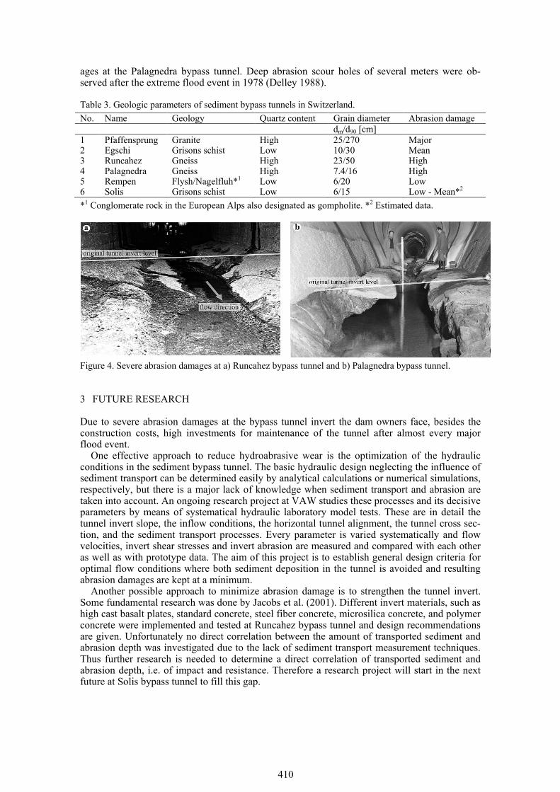
2.2.2 Abrasion problem According to Chervet & Vischer (1996), Vischer et al. (1997), Sumi (2000, 2005), Sumi et al. (2004), and Inoue (2009) a severe problem affecting nearly all sediment bypass tunnels is the hydro-abrasion of the tunnel invert due to the combination of high flow velocities together with a great amount of transported sediment. Depending mainly on the geologic conditions in the catchment, the impact on the tunnel invert abrasion differs. Both high quartz content and high mean grain diameters contribute to high abrasion damages in the tunnel. Table 3 presents the geologic parameters of the Swiss bypass tunnels according to Chervet & Vischer (1996). It can be stated that hard rock like granite and gneiss combined with a high quartz content lead to high abrasion damages at the tunnel invert. Figure 4 a shows an example of severe abrasion damage at the Runcahez bypass tunnel invert. The original tunnel cross section is of archway type implying a plain tunnel invert. Abrasion depths up to 1.20 m were measured (Jacobs et al. 2001). Figure 4 b shows severe abrasion dam-
410
ages at the Palagnedra bypass tunnel. Deep abrasion scour holes of several meters were ob-served after the extreme flood event in 1978 (Delley 1988).
Table 3. Geologic parameters of sediment bypass tunnels in Switzerland. No. Name Geology Quartz content Grain diameter Abrasion damage dm/d90 [cm] 1 2 3 4 5 6
Pfaffensprung Egschi Runcahez Palagnedra Rempen Solis
Granite Grisons schist Gneiss Gneiss Flysh/Nagelfluh*1
Grisons schist
High Low High High Low Low
25/270 10/30 23/50 7.4/16 6/20 6/15
Major Mean High High Low Low - Mean*2
*1 Conglomerate rock in the European Alps also designated as gompholite. *2 Estimated data.
Figure 4. Severe abrasion damages at a) Runcahez bypass tunnel and b) Palagnedra bypass tunnel.
3 FUTURE RESEARCH
Due to severe abrasion damages at the bypass tunnel invert the dam owners face, besides the construction costs, high investments for maintenance of the tunnel after almost every major flood event.
One effective approach to reduce hydroabrasive wear is the optimization of the hydraulic conditions in the sediment bypass tunnel. The basic hydraulic design neglecting the influence of sediment transport can be determined easily by analytical calculations or numerical simulations, respectively, but there is a major lack of knowledge when sediment transport and abrasion are taken into account. An ongoing research project at VAW studies these processes and its decisive parameters by means of systematical hydraulic laboratory model tests. These are in detail the tunnel invert slope, the inflow conditions, the horizontal tunnel alignment, the tunnel cross sec-tion, and the sediment transport processes. Every parameter is varied systematically and flow velocities, invert shear stresses and invert abrasion are measured and compared with each other as well as with prototype data. The aim of this project is to establish general design criteria for optimal flow conditions where both sediment deposition in the tunnel is avoided and resulting abrasion damages are kept at a minimum.
Another possible approach to minimize abrasion damage is to strengthen the tunnel invert. Some fundamental research was done by Jacobs et al. (2001). Different invert materials, such as high cast basalt plates, standard concrete, steel fiber concrete, microsilica concrete, and polymer concrete were implemented and tested at Runcahez bypass tunnel and design recommendations are given. Unfortunately no direct correlation between the amount of transported sediment and abrasion depth was investigated due to the lack of sediment transport measurement techniques. Thus further research is needed to determine a direct correlation of transported sediment and abrasion depth, i.e. of impact and resistance. Therefore a research project will start in the next future at Solis bypass tunnel to fill this gap.

411
4 CONCLUSION
Reservoir sedimentation is a severe and increasing problem concerning nearly all reservoirs worldwide. The construction of a sediment bypass tunnel to route the sediments from the up-stream to the downstream river reach is therefore a very effective countermeasure to stop or at least significantly decrease the sediment accumulation. Worldwide there are few bypass tunnels in operation up to date. Leading countries in sediment bypass tunnel construction are mainly Switzerland and Japan having eleven bypass tunnels in all.
In this paper, the state-of-the-art design of sediment bypass tunnels is presented. Descriptions of both tunnel operation and every individual sediment bypass tunnel element are given. These are namely the tunnel intake location, the method of tunnel operation, the design discharge, the guiding structure, the tunnel intake, the steeply sloped acceleration section, the smoothly sloped tunnel section, and the outlet structure.
Quasi all bypass tunnels in operation are facing an abrasion problem. Due to high flow veloc-ities in combination with high sediment load abrasion of the tunnel invert is significant leading to major recurring maintenance costs. Having in mind that design of sediment bypass tunnels depends on both the hydraulic and the sedimentologic conditions a suitable layout is difficult. Whereas the basic hydraulic design is easy to determine, a crucial lack of knowledge exists in considering the sediment transport processes in the tunnel. Therefore a research project at VAW is launched focusing on sediment transport in bypass tunnels accounting for the invert abrasion.
ACKNOWLEDGMENTS
The authors would like to thank swisselectric research for their financial support.
REFERENCES
Annandale, G. W. 1987. Reservoir sedimentation. Developments in water science No. 29. Elsevier Sci-ence Publishers B.V., The Netherlands.
Auel, C., Berchtold, T. & Boes, R. 2010. Sediment management in the Solis reservoir using a bypass tun-nel. Proc. of the 8th ICOLD European Club Symposium. Innsbruck, Austria.
Basson, G. R. 2009. Management of siltation in existing and new reservoirs. General Report Q. 89, Proc. 23rd ICOLD Congress. Brasilia, Brazil.
Boes, R. & Reindl, R. 2006. Nachhaltige Maßnahmen gegen Stauraumverlandungen alpiner Speicher [in German]. Proc. Symposium "Stauhaltungen und Speicher - von der Tradition zur Moderne", Bericht 46/1, TU Graz, Austria: 179-193.
Boillat, J.-L., De Cesare, G, Schleiss, A. & Oehy, C. 2000. Successful sediment flushing conditions in Alpine reservoirs. Proc. Int. Workshop and Symposium on Reservoir Sedimentation Management. 26-27 October 2000. Tokyo, Japan.
Chervet, A. & Vischer, D. 1996. Geschiebeumleitstollen bei Stauseen; Möglichkeiten und Grenzen [in German]. Int. Symposium: Verlandung von Stauseen und Stauhaltungen, Sedimentprobleme in Leitun-gen und Kanälen, VAW-Mitteilung No. 143, ETH Zurich, 25-43.
Delley, P. 1988. Erosionsschäden im Spülstollen Palagnedra und deren Sanierung [in French]. Int. Sym-posium - Erosion, Abrasion und Kavitation im Wasserbau, VAW-Mitteilung No. 99, ed.: D. Vischer, ETH Zurich, 329-352.
Harada, M., Terada, M. & Kokubo, T. 1997. Planning and hydraulic design of bypass tunnel for sluicing sediments past Asahi reservoir. C. 9, Proc. 19th ICOLD Congress. Florence, Italy.
Inoue, M. 2009. Promotion of field-verified studies on sediment transport systems covering mountains, rivers, and coasts. Science & Technology Foresight Center, NISTEP. Quarterly Review No. 33. 89-107.
Jacobs, F., Winkler, K., Hunkeler, F. & Volkart, P. 2001. Betonabrasion im Wasserbau [in German]. VAW-Mitteilung No. 168, ed. H.-E. Minor, ETH Zurich.
Kantoush, S. & Sumi, T. 2010. River morphology and sediment management strategies for sustainable reservoir in Japan and Switzerland. Annuals of Disaster Prevention Research Institute, No. 53 B. Kyo-to, Japan.
Kashiwai, J., Sumi, T. & Honda, T. 1997. Hydraulic study on diversion facilities required for sediment bypass systems. Q. 74, R. 59, Proc. 19th ICOLD Congress. Florence, Italy.

412
Lai, J.-S. & Shen, H.W. 1996. Flushing sediment through reservoirs. Journal of Hydraulic Research: 34 (2), 237-255.
Mariño, J. J., Castro, H., Manjarrés, F., Gámez, J., Daza, A. & Alarcón, W. 2009. Sediment management at the Chivor hydroelectric project in Colombia. Q. 89 R. 15, Proc. 23rd ICOLD Congress. Brasilia, Brazil.
Meshkati, M. E., Dehghani, A. A., Naser, G., Emamgholizadeh, S. & Mosaedi, A. 2009. Evolution of de-veloping flushing cone during pressurized flushing in reservoir storage. World Academy of Science, Engineering and Technology: 58, 1107-1111.
Müller, P. & De Cesare, G. 2009. Sedimentation problems in the reservoirs of the Kraftwerke Sarganser-land – venting of turbidity currents as the essential part of the solution. Q. 89 R. 21, Proc. 23rd ICOLD Congress. Brasilia, Brazil.
Schleiss, A. & Oehy, C. 2002. Verlandung von Stauseen und Nachhaltigkeit [in German]. Wasser, Ener-gie, Luft, 94(7/8): 227-234.
Schleiss, A., De Cesare, G. & Jenzer Althaus, J. 2010. Verlandung der Stauseen gefährdet die nachhaltige Nutzung der Wasserkraft [in German]. Wasser Energie Luft, 102(1): 31-40.
Sloff, C. J. 1991. Reservoir sedimentation: a literature survey. Communications on hydraulic and ge-otechnical engineering Report No 91-2, TU Delft, The Netherlands.
Sumi, T. 2000. Future perspective of dam reservoir sediment management. Proc. of Int. Workshop on Reservoir Sedimentation Management. 145-156.
Sumi, T. 2005. Sediment flushing efficiency and selection of environmentally compatible reservoir sedi-ment management measures. Int. Symposium on Sediment Management and Dams, 2nd EADC Sympo-sium. 25-26 October 2005. Yokohama, Japan.
Sumi, T., Okano, M. & Takata, Y. 2004. Reservoir sedimentation management with bypass tunnels in Ja-pan. Proc. 9th International Symposium on River Sedimentation. Yichang, China, 1036-1043.
Sumi, T, Kobayashi, K., Yamaguchi, K. & Takata, Y. 2009. Study on the applicability of the asset man-agement for reservoir sediment management. Q. 89 R. 4, Proc. 23rd ICOLD Congress. Brasilia, Brazil.
Vischer, D. (ed.) 1981. Int. symposium: Verlandung von Stauhaltungen und Speicherseen im Alpenraum [in German]. VAW-Mitteilung No. 53, ETH Zurich.
Vischer, D. (ed.) 1996. Int. symposium: Verlandung von Stauseen und Stauhaltungen, Sedimentprobleme in Leitungen und Kanälen [in German]. VAW-Mitteilung No. 142 & 143, ETH Zurich.
Vischer, D., Hager, W. H., Casanova, C., Joos, B., Lier, P. & Martini, O. 1997. Bypass tunnels to prevent reservoir sedimentation. Q. 74 R. 37, Proc. 19th ICOLD Congress. Florence, Italy.
View publication statsView publication stats