Embed Size (px)
Citation preview
© Catchments & Creeks Pty Ltd Version 2 - April 2010 Page 1
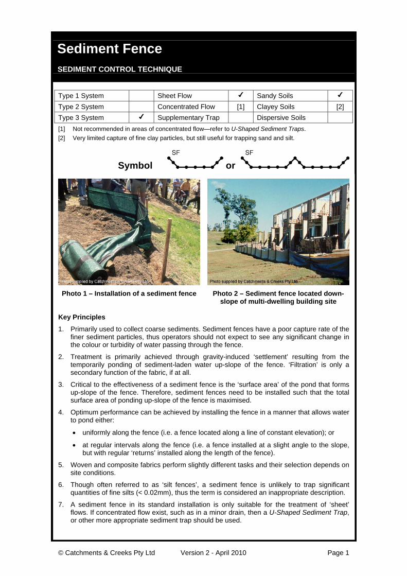
Sediment Fence SEDIMENT CONTROL TECHNIQUE
Type 1 System Sheet Flow ✔ Sandy Soils ✔
Type 2 System Concentrated Flow [1] Clayey Soils [2]Type 3 System ✔ Supplementary Trap Dispersive Soils[1] Not recommended in areas of concentrated flow—refer to U-Shaped Sediment Traps.[2] Very limited capture of fine clay particles, but still useful for trapping sand and silt.
Symbol or
Photo 1 – Installation of a sediment fence Photo 2 – Sediment fence located down-slope of multi-dwelling building site
Key Principles
1. Primarily used to collect coarse sediments. Sediment fences have a poor capture rate of thefiner sediment particles, thus operators should not expect to see any significant change inthe colour or turbidity of water passing through the fence.
2. Treatment is primarily achieved through gravity-induced ‘settlement’ resulting from thetemporarily ponding of sediment-laden water up-slope of the fence. ‘Filtration’ is only asecondary function of the fabric, if at all.
3. Critical to the effectiveness of a sediment fence is the ‘surface area’ of the pond that formsup-slope of the fence. Therefore, sediment fences need to be installed such that the totalsurface area of ponding up-slope of the fence is maximised.
4. Optimum performance can be achieved by installing the fence in a manner that allows waterto pond either:
• uniformly along the fence (i.e. a fence located along a line of constant elevation); or
• at regular intervals along the fence (i.e. a fence installed at a slight angle to the slope,but with regular ‘returns’ installed along the length of the fence).
5. Woven and composite fabrics perform slightly different tasks and their selection depends onsite conditions.
6. Though often referred to as ‘silt fences’, a sediment fence is unlikely to trap significantquantities of fine silts (< 0.02mm), thus the term is considered an inappropriate description.
7. A sediment fence in its standard installation is only suitable for the treatment of ‘sheet’flows. If concentrated flow exist, such as in a minor drain, then a U-Shaped Sediment Trap,or other more appropriate sediment trap should be used.
© Catchments & Creeks Pty Ltd Version 2 - April 2010 Page 2
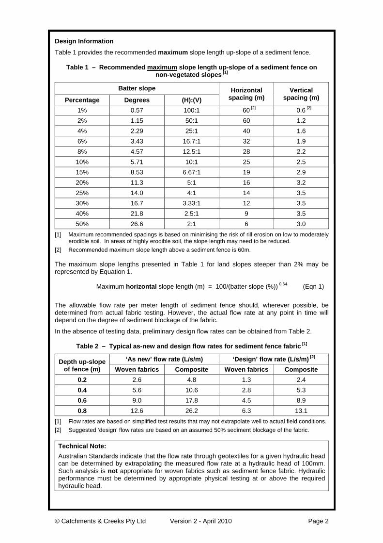
Design Information
Table 1 provides the recommended maximum slope length up-slope of a sediment fence.
Table 1 – Recommended maximum slope length up-slope of a sediment fence onnon-vegetated slopes [1]
Batter slope
Percentage Degrees (H):(V)Horizontal
spacing (m)Vertical
spacing (m)
1% 0.57 100:1 60 [2] 0.6 [2]
2% 1.15 50:1 60 1.24% 2.29 25:1 40 1.66% 3.43 16.7:1 32 1.98% 4.57 12.5:1 28 2.210% 5.71 10:1 25 2.515% 8.53 6.67:1 19 2.920% 11.3 5:1 16 3.225% 14.0 4:1 14 3.530% 16.7 3.33:1 12 3.540% 21.8 2.5:1 9 3.550% 26.6 2:1 6 3.0
[1] Maximum recommended spacings is based on minimising the risk of rill erosion on low to moderatelyerodible soil. In areas of highly erodible soil, the slope length may need to be reduced.
[2] Recommended maximum slope length above a sediment fence is 60m.
The maximum slope lengths presented in Table 1 for land slopes steeper than 2% may berepresented by Equation 1.
Maximum horizontal slope length (m) = 100/(batter slope (%)) 0.64 (Eqn 1)
The allowable flow rate per meter length of sediment fence should, wherever possible, bedetermined from actual fabric testing. However, the actual flow rate at any point in time willdepend on the degree of sediment blockage of the fabric.
In the absence of testing data, preliminary design flow rates can be obtained from Table 2.
Table 2 – Typical as-new and design flow rates for sediment fence fabric [1]
‘As new’ flow rate (L/s/m) ‘Design’ flow rate (L/s/m) [2]Depth up-slope
of fence (m) Woven fabrics Composite Woven fabrics Composite0.2 2.6 4.8 1.3 2.40.4 5.6 10.6 2.8 5.30.6 9.0 17.8 4.5 8.90.8 12.6 26.2 6.3 13.1
[1] Flow rates are based on simplified test results that may not extrapolate well to actual field conditions.[2] Suggested ‘design’ flow rates are based on an assumed 50% sediment blockage of the fabric.
Technical Note:Australian Standards indicate that the flow rate through geotextiles for a given hydraulic headcan be determined by extrapolating the measured flow rate at a hydraulic head of 100mm.Such analysis is not appropriate for woven fabrics such as sediment fence fabric. Hydraulicperformance must be determined by appropriate physical testing at or above the requiredhydraulic head.
© Catchments & Creeks Pty Ltd Version 2 - April 2010 Page 3
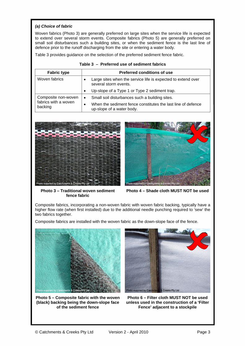
(a) Choice of fabric
Woven fabrics (Photo 3) are generally preferred on large sites when the service life is expectedto extend over several storm events. Composite fabrics (Photo 5) are generally preferred onsmall soil disturbances such a building sites, or when the sediment fence is the last line ofdefence prior to the runoff discharging from the site or entering a water body.
Table 3 provides guidance on the selection of the preferred sediment fence fabric.
Table 3 – Preferred use of sediment fabrics
Fabric type Preferred conditions of useWoven fabrics • Large sites when the service life is expected to extend over
several storm events.• Up-slope of a Type 1 or Type 2 sediment trap.
Composite non-wovenfabrics with a wovenbacking
• Small soil disturbances such a building sites.• When the sediment fence constitutes the last line of defence
up-slope of a water body.
Photo 3 – Traditional woven sedimentfence fabric
Photo 4 – Shade cloth MUST NOT be used
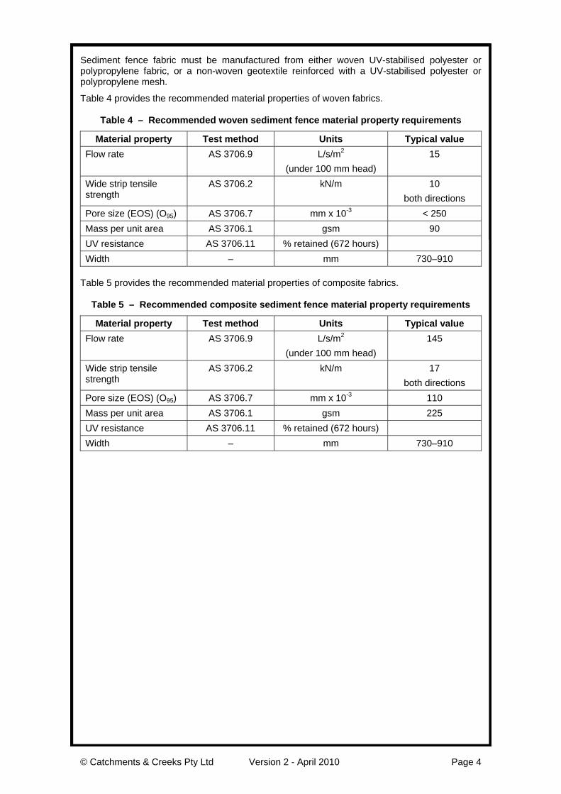
Composite fabrics, incorporating a non-woven fabric with woven fabric backing, typically have ahigher flow rate (when first installed) due to the additional needle punching required to ‘sew’ thetwo fabrics together.
Composite fabrics are installed with the woven fabric as the down-slope face of the fence.
Photo 5 – Composite fabric with the woven(black) backing being the down-slope face
of the sediment fence
Photo 6 – Filter cloth MUST NOT be usedunless used in the construction of a ‘Filter
Fence’ adjacent to a stockpile
© Catchments & Creeks Pty Ltd Version 2 - April 2010 Page 4
Sediment fence fabric must be manufactured from either woven UV-stabilised polyester orpolypropylene fabric, or a non-woven geotextile reinforced with a UV-stabilised polyester orpolypropylene mesh.
Table 4 provides the recommended material properties of woven fabrics.
Table 4 – Recommended woven sediment fence material property requirements
Material property Test method Units Typical valueFlow rate AS 3706.9 L/s/m2
(under 100 mm head)15
Wide strip tensilestrength
AS 3706.2 kN/m 10both directions
Pore size (EOS) (O95) AS 3706.7 mm x 10-3 < 250Mass per unit area AS 3706.1 gsm 90UV resistance AS 3706.11 % retained (672 hours)Width – mm 730–910
Table 5 provides the recommended material properties of composite fabrics.
Table 5 – Recommended composite sediment fence material property requirements
Material property Test method Units Typical valueFlow rate AS 3706.9 L/s/m2
(under 100 mm head)145
Wide strip tensilestrength
AS 3706.2 kN/m 17both directions
Pore size (EOS) (O95) AS 3706.7 mm x 10-3 110Mass per unit area AS 3706.1 gsm 225UV resistance AS 3706.11 % retained (672 hours)Width – mm 730–910
© Catchments & Creeks Pty Ltd Version 2 - April 2010 Page 5
(b) Location of a sediment fence
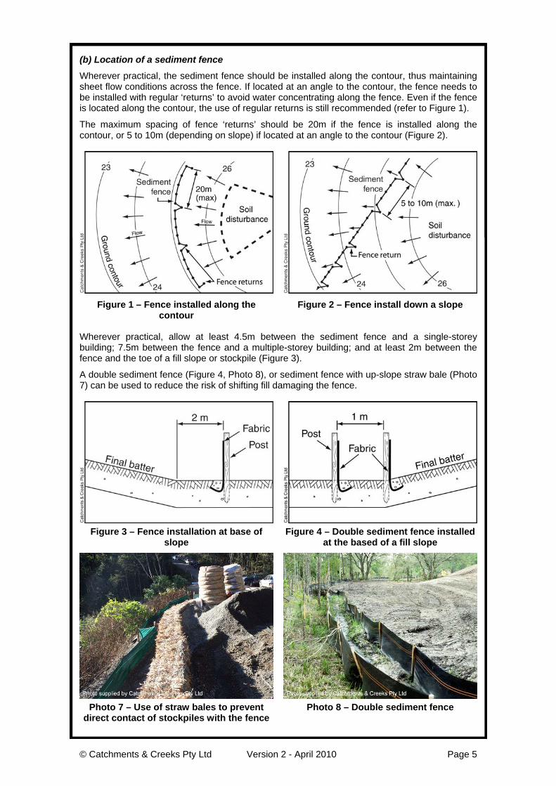
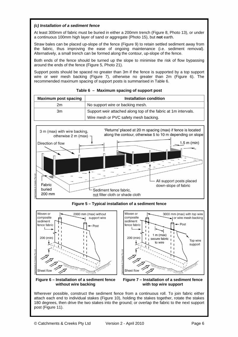
Wherever practical, the sediment fence should be installed along the contour, thus maintainingsheet flow conditions across the fence. If located at an angle to the contour, the fence needs tobe installed with regular ‘returns’ to avoid water concentrating along the fence. Even if the fenceis located along the contour, the use of regular returns is still recommended (refer to Figure 1).
The maximum spacing of fence ‘returns’ should be 20m if the fence is installed along thecontour, or 5 to 10m (depending on slope) if located at an angle to the contour (Figure 2).
Figure 1 – Fence installed along thecontour
Figure 2 – Fence install down a slope
Wherever practical, allow at least 4.5m between the sediment fence and a single-storeybuilding; 7.5m between the fence and a multiple-storey building; and at least 2m between thefence and the toe of a fill slope or stockpile (Figure 3).
A double sediment fence (Figure 4, Photo 8), or sediment fence with up-slope straw bale (Photo7) can be used to reduce the risk of shifting fill damaging the fence.
Figure 3 – Fence installation at base ofslope
Figure 4 – Double sediment fence installedat the based of a fill slope
Photo 7 – Use of straw bales to preventdirect contact of stockpiles with the fence
Photo 8 – Double sediment fence
© Catchments & Creeks Pty Ltd Version 2 - April 2010 Page 6
(c) Installation of a sediment fence
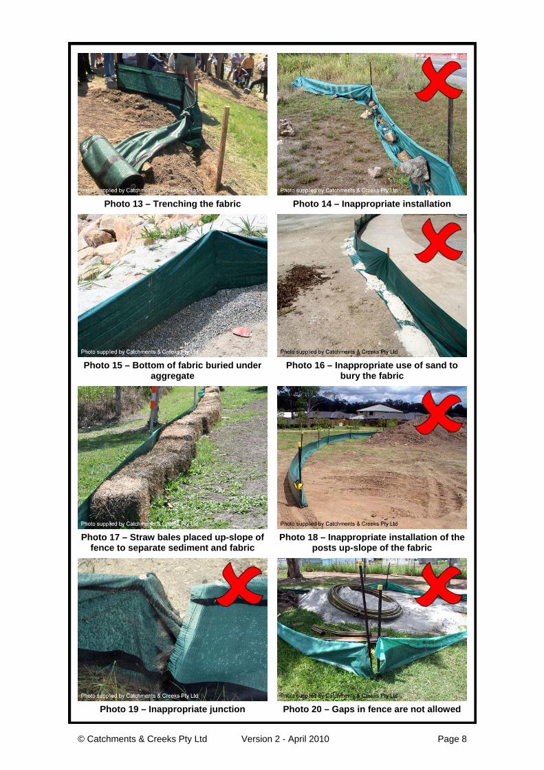
At least 300mm of fabric must be buried in either a 200mm trench (Figure 8, Photo 13), or undera continuous 100mm high layer of sand or aggregate (Photo 15), but not earth.
Straw bales can be placed up-slope of the fence (Figure 9) to retain settled sediment away fromthe fabric, thus improving the ease of ongoing maintenance (i.e. sediment removal).Alternatively, a small trench can be formed along the contour, up-slope of the fence.
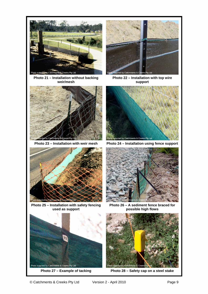
Both ends of the fence should be turned up the slope to minimise the risk of flow bypassingaround the ends of the fence (Figure 5, Photo 21).
Support posts should be spaced no greater than 3m if the fence is supported by a top supportwire or weir mesh backing (Figure 7), otherwise no greater than 2m (Figure 6). Therecommended maximum spacing of support posts is summarised in Table 6.
Table 6 – Maximum spacing of support post
Maximum post spacing Installation condition2m No support wire or backing mesh.3m Support weir attached along top of the fabric at 1m intervals.
Wire mesh or PVC safety mesh backing.
Figure 5 – Typical installation of a sediment fence
Figure 6 – Installation of a sediment fencewithout wire backing
Figure 7 – Installation of a sediment fencewith top wire support
Wherever possible, construct the sediment fence from a continuous roll. To join fabric eitherattach each end to individual stakes (Figure 10), holding the stakes together, rotate the stakes180 degrees, then drive the two stakes into the ground; or overlap the fabric to the next supportpost (Figure 11).
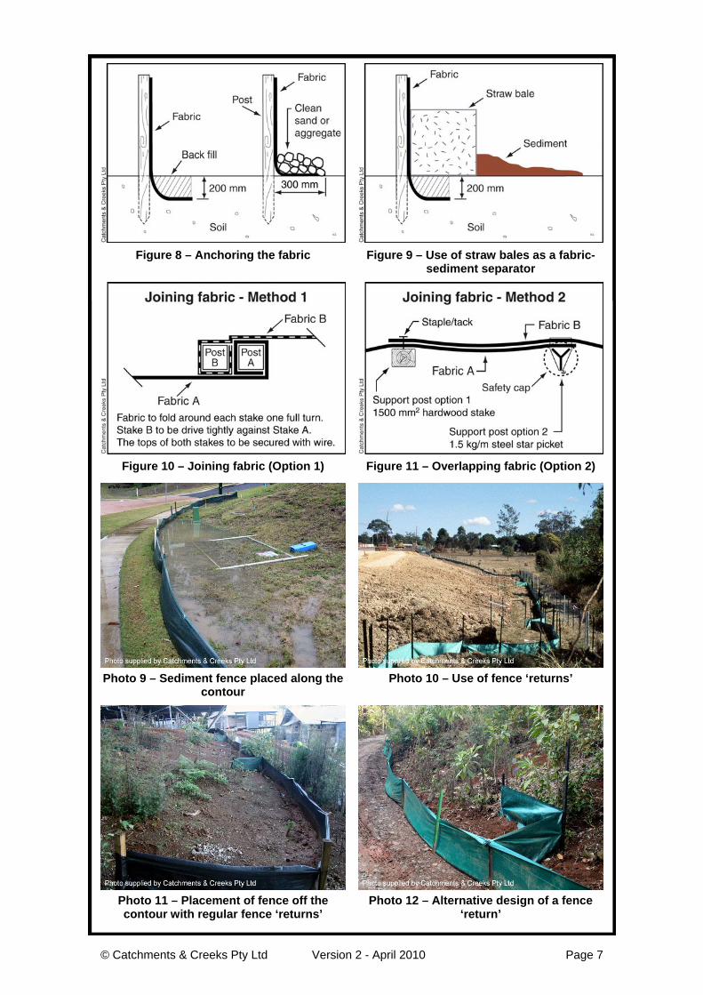
© Catchments & Creeks Pty Ltd Version 2 - April 2010 Page 7
Figure 8 – Anchoring the fabric Figure 9 – Use of straw bales as a fabric-sediment separator
Figure 10 – Joining fabric (Option 1) Figure 11 – Overlapping fabric (Option 2)
Photo 9 – Sediment fence placed along thecontour
Photo 10 – Use of fence ‘returns’
Photo 11 – Placement of fence off thecontour with regular fence ‘returns’
Photo 12 – Alternative design of a fence‘return’
© Catchments & Creeks Pty Ltd Version 2 - April 2010 Page 8
Photo 13 – Trenching the fabric Photo 14 – Inappropriate installation
Photo 15 – Bottom of fabric buried underaggregate
Photo 16 – Inappropriate use of sand tobury the fabric
Photo 17 – Straw bales placed up-slope offence to separate sediment and fabric
Photo 18 – Inappropriate installation of theposts up-slope of the fabric
Photo 19 – Inappropriate junction Photo 20 – Gaps in fence are not allowed
© Catchments & Creeks Pty Ltd Version 2 - April 2010 Page 9
Photo 21 – Installation without backingweir/mesh
Photo 22 – Installation with top wiresupport
Photo 23 – Installation with weir mesh Photo 24 – Installation using fence support
Photo 25 – Installation with safety fencingused as support
Photo 26 – A sediment fence braced forpossible high flows
Photo 27 – Example of tacking Photo 28 – Safety cap on a steel stake
© Catchments & Creeks Pty Ltd Version 2 - April 2010 Page 10
Photo 29 – Flow diversion by fence Photo 30 – No end return
Photo 31 – Damage by shifting fill Photo 32 – Fence placed too close to fill
Photo 33 – Evidence of hydraulic wash-outunder fence caused by poor trenching
Photo 34 – Sediment not removed afterstorm
Photo 35 – Flow allowed to bypass thefence
Photo 36 – Spill-through weirs must notdischarge onto unstable land
© Catchments & Creeks Pty Ltd Version 2 - April 2010 Page 11
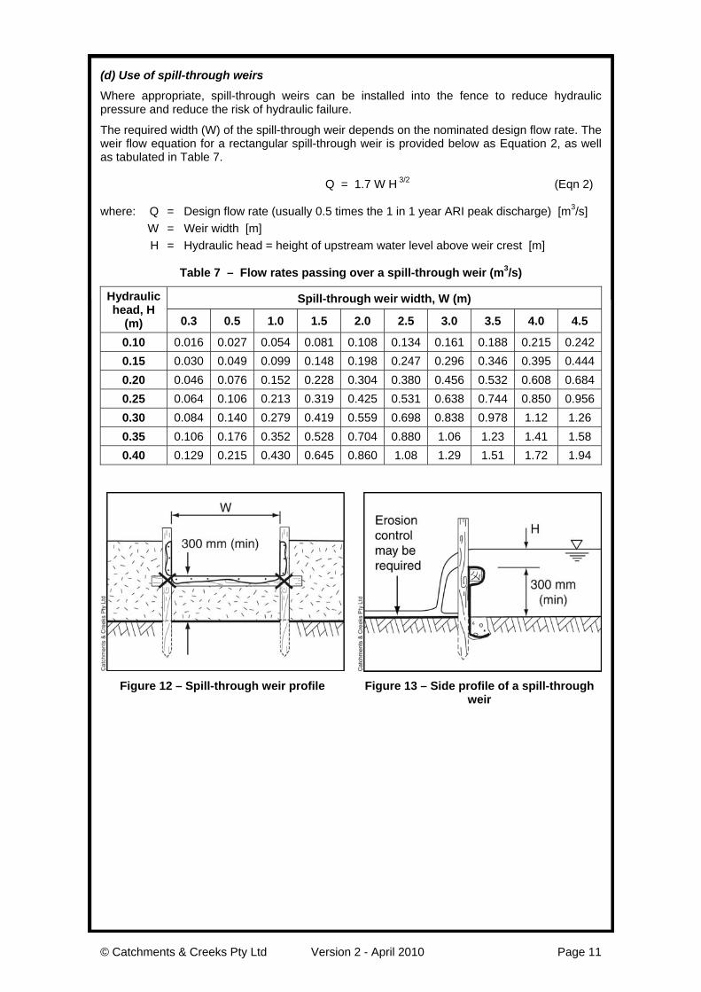
(d) Use of spill-through weirs
Where appropriate, spill-through weirs can be installed into the fence to reduce hydraulicpressure and reduce the risk of hydraulic failure.
The required width (W) of the spill-through weir depends on the nominated design flow rate. Theweir flow equation for a rectangular spill-through weir is provided below as Equation 2, as wellas tabulated in Table 7.
Q = 1.7 W H 3/2 (Eqn 2)
where: Q = Design flow rate (usually 0.5 times the 1 in 1 year ARI peak discharge) [m3/s]W = Weir width [m]H = Hydraulic head = height of upstream water level above weir crest [m]
Table 7 – Flow rates passing over a spill-through weir (m3/s)
Spill-through weir width, W (m)Hydraulichead, H
(m) 0.3 0.5 1.0 1.5 2.0 2.5 3.0 3.5 4.0 4.5
0.10 0.016 0.027 0.054 0.081 0.108 0.134 0.161 0.188 0.215 0.2420.15 0.030 0.049 0.099 0.148 0.198 0.247 0.296 0.346 0.395 0.4440.20 0.046 0.076 0.152 0.228 0.304 0.380 0.456 0.532 0.608 0.6840.25 0.064 0.106 0.213 0.319 0.425 0.531 0.638 0.744 0.850 0.9560.30 0.084 0.140 0.279 0.419 0.559 0.698 0.838 0.978 1.12 1.260.35 0.106 0.176 0.352 0.528 0.704 0.880 1.06 1.23 1.41 1.580.40 0.129 0.215 0.430 0.645 0.860 1.08 1.29 1.51 1.72 1.94
Figure 12 – Spill-through weir profile Figure 13 – Side profile of a spill-throughweir
© Catchments & Creeks Pty Ltd Version 2 - April 2010 Page 12
Photo 37 – Spill-through weir (down-slopeside) with rock splash pad
Photo 38 – Spill-through weir with outletchute
Photo 39 – Spill-through weir with up-slopeaggregate filter
Photo 40 – Inappropriate placement offence and installation of spill-through weir
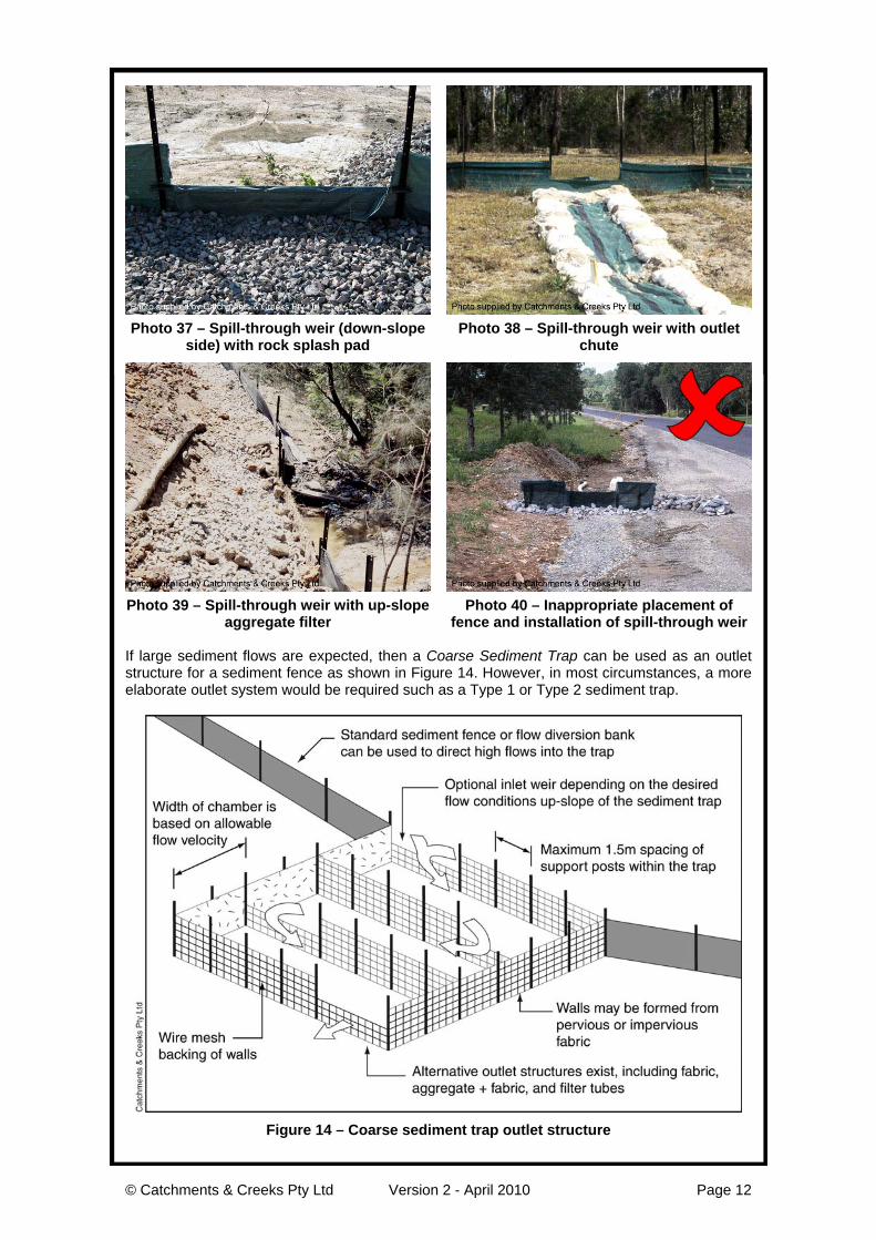
If large sediment flows are expected, then a Coarse Sediment Trap can be used as an outletstructure for a sediment fence as shown in Figure 14. However, in most circumstances, a moreelaborate outlet system would be required such as a Type 1 or Type 2 sediment trap.
Figure 14 – Coarse sediment trap outlet structure
© Catchments & Creeks Pty Ltd Version 2 - April 2010 Page 13
Description
A sediment fence consists of speciallymanufactured woven fabric attached tosupport posts. The typical height of thefence is around 600 to 700mm.
Most sediment fences are self-supporting;however, in appropriate circumstances thefence may be attached to an existingporous structure such as a property fence.
The fabric may be manufactured from eitherwoven fabric, or a composite of woven andnon-woven fabrics. The incorporation of awoven fabric is essential for the control ofwater flow needed to allow adequatetemporary ponding up-slope of the fence.
Purpose
Used as a Type 3 sediment trap on smallcatchments, or as a supplement to Type 1or 2 sediment traps on large catchments.
Limitations
Though often referred to as a ‘silt fence’,these Type 3 sediment traps have littleimpact on fine silts (< 0.02mm).
A sediment fence in its standard installationis only suitable for the treatment of ‘sheet’flows. If concentrated flow exist, such as ina minor drain, then a U-Shaped SedimentTrap, or other more appropriate sedimenttrap should be used.
Most fabrics have an effective service life ofaround 6 months (check with manufactureror distributor).
Advantages
Reasonably easy to install.
Has the ability to control sediment runoffclose to the source of the erosion.
Disadvantages
Time-consuming to install, which oftenresults in poor installation.
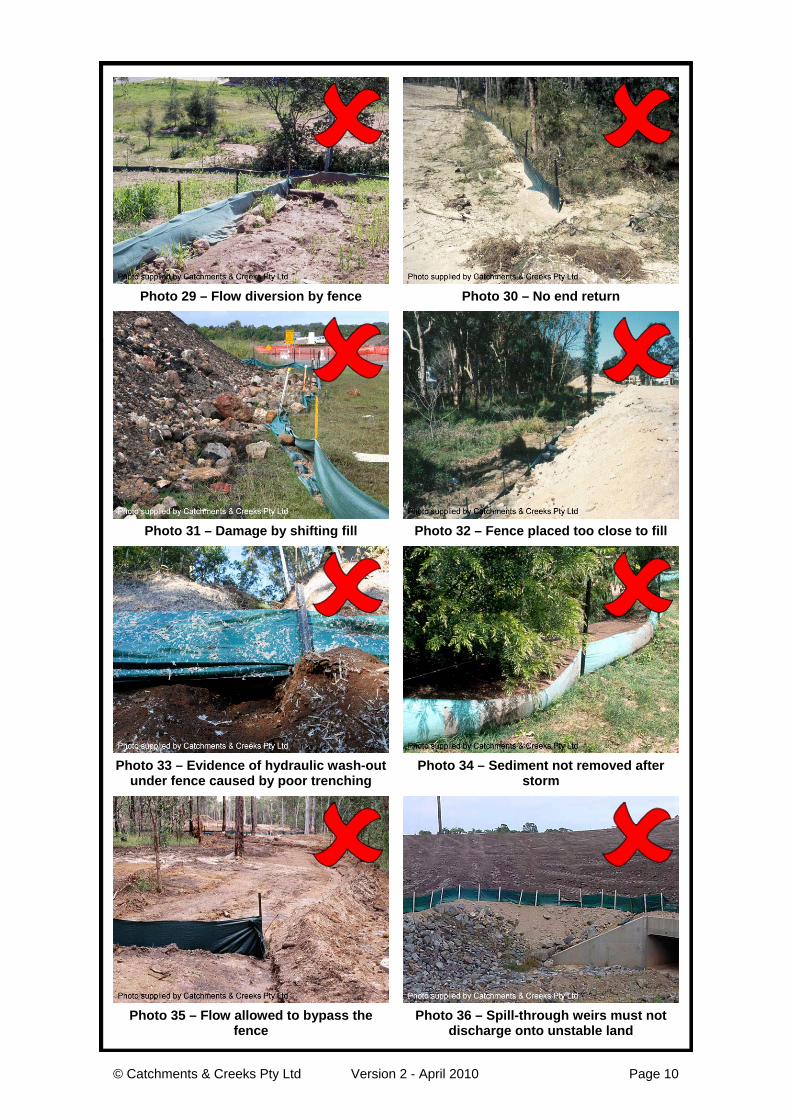
Easily damaged by construction equipmentand shifting earth (Photos 31 & 32).
Can cause the concentration of stormwaterrunoff if poorly located, or installed.
Sediment fences are one of the mostmissed used sediment control devices,usually because they are either not installedin appropriate locations, or are installed in amanner that does not allow adequatelywater ponding up-slope of the fences.
Common Problems
If not installed along the contour, asediment fence can result in flows beingdeflected along the fence (Photo 29).
If the ends of the fence are not turned upthe slope, water and sediment can passaround the end of the fence (Photo 30).
If gaps exist in the fence (Photos 19 & 20),then water is prevented from ponding up-slope of the fence, thus sedimentation doesnot occur.
Excessive spacing between support postsis a common problem. In extreme casesthis can result in the fabric sagging close tothe ground.
Fabric not adequately connected to thesupport posts or backing wire.
The bottom of the fabric not adequatelyburied into the ground or under a suitablelayer of sand or aggregate. If such fencesare subjected to significant storms, thebottom of the fence can ‘blow-out’ causingerosion down-slope of the fence (Photo 33).
Spill-through weirs may not have beeninstalled in large catchments or areas ofhigh rainfall, thus increasing the risk of flowdamage to the fence.
Crest of spill-through weir set too close tothe ground (should be at least 300mmabove ground level).
Crest of spill-through weir is set above theground level at the ends of the fence, thusallowing flow bypassing rather thandischarge over the weir (Photo 40).
Special Requirements
Woven fabrics are generally preferred onlarge sites when the service life is expectedto extend over several storm events.Composite fabrics are generally preferredon small soil disturbances such a buildingsites, or when the sediment fence is the lastline of defence prior to the runoff entering awater body.
Ideally, the sediment fence should beinstalled along the contour, thusmaintaining sheet flow conditions acrossfence. If located across the contour, thefence should be installed with regular‘returns’ to avoid water concentrating alongthe fence.
At least 300mm of fabric must be buried ineither a 200mm trench, or under acontinuous, 100mm high layer of sand oraggregate, but not earth.
© Catchments & Creeks Pty Ltd Version 2 - April 2010 Page 14
Straw bales can be placed up-slope of thefence to retain bulk sediment away from thefabric, thus improving the ease of sedimentremoval. Alternatively, a small trench canbe formed along the contour, up-slope ofthe fence. However, in all cases the aimshould be to minimise high sediment flowsso that such fence modifications becomethe exception, not the rule!
Where appropriate, spill-through weirs canbe installed into the fence to reducehydraulic pressure and reduce the risk ofhydraulic failure.
Location
Install along the contour wherever possible.
Allow at least 4.5m between the fence andsingle-story buildings; 7.5m between thefence and multiple-story buildings; and atleast 2m between the fence and the toe of afill slope or stockpile.
Site Inspection
Ensure the sediment fence will adequatelypond water up-slope of the fence.
Ensure the fabric is adequately buried.
Check the spacing of support posts/stakes.
Check for excessive sediment deposition.
Investigate the source of excessivesediment deposits.
Ensure the selection of appropriate fabric(i.e. woven or composite).
Check for damage to the fabric.
Check for erosion down-slope of any spill-through weirs.
Ensure the fence is not concentrating ordiverting flows in an undesirable manner.
Materials
• Fabric: polypropylene, polyamide,nylon, polyester, or polyethylene wovenor non-woven fabric, at least 700mm inwidth and a minimum unit weight of140GSM. All fabrics to containultraviolet inhibitors and stabilisers toprovide a minimum of 6 months ofuseable construction life (ultravioletstability exceeding 70%).
• Fabric reinforcement: wire or steelmesh minimum 14-gauge with amaximum mesh spacing of 200mm.
• Support posts/stakes: 1500mm2 (min)hardwood, 2500mm2 (min) softwood, or1.5kg/m (min) steel star pickets suitablefor attaching fabric.
Installation
1. Refer to approved plans for location,extent, and required type of fabric (ifspecified). If there are questions orproblems with the location, extent,fabric type, or method of installationcontact the engineer or responsible on-site officer for assistance.
2. To the maximum degree practical, andwhere the plans allow, ensure the fenceis located: (i) totally within the property
boundaries; (ii) along a line of constant elevation
wherever practical; (iii) at least 2m from the toe of any filling
operations that may result in shiftingsoil/fill damaging the fence.
3. Install returns within the fence atmaximum 20m intervals if the fence isinstalled along the contour, or 5 to 10mmaximum spacing (depending onslope) if the fence is installed at anangle to the contour. The ‘returns’ shallconsist of either: (i) V-shaped section extending at least
1.5m up the slope; or (ii) sandbag or rock/aggregate check
dam a minimum 1/3 and maximum1/2 fence height, and extending atleast 1.5m up the slope.
4. Ensure the extreme ends of the fenceare turned up the slope at least 1.5m,or as necessary, to minimise waterbypassing around the fence.
5. Ensure the sediment fence is installedin a manner that avoids theconcentration of flow along the fence,and the undesirable discharge of wateraround the ends of the fence.
6. If the sediment fence is to be installedalong the edge of existing trees, ensurecare is taken to protect the trees andtheir root systems during installation ofthe fence. Do not attach the fabric tothe trees.
7. Unless directed by the site supervisoror the approved plans, excavate a200mm wide by 200mm deep trenchalong the proposed fence line, placingthe excavated material on the up-slopeside of the trench.
© Catchments & Creeks Pty Ltd Version 2 - April 2010 Page 15
8. Along the lower side of the trench,appropriately secure the stakes into theground spaced no greater than 3m ifsupported by a top support wire or weirmesh backing, otherwise no greaterthan 2m.
9. If specified, securely attach the supportwire or mesh to the up-slope side of thestakes with the mesh extending at least200mm into the excavated trench.Ensure the mesh and fabric is attachedto the up-slope side of the stakes evenwhen directing a fence around a corneror sharp change-of-direction.
10. Wherever possible, construct thesediment fence from a continuous rollof fabric. To join fabric either: (i) attach each end to two overlapping
stakes with the fabric folding aroundthe associated stake one turn, andwith the two stakes tied together withwire (Method 1); or
(ii) overlap the fabric to the nextadjacent support post (Method 2).
11. Securely attach the fabric to the supportposts using 25 x 12.5mm staples, or tiewire at maximum 150mm spacing.
12. Securely attach the fabric to the supportwire/mesh (if any) at a maximumspacing of 1m.
13. Ensure the completed sediment fenceis at least 450mm, but not more than700mm high. If a spill-though weir isinstalled, ensure the crest of the weir isat least 300mm above ground level.
14. Backfill the trench and tamp the fill tofirmly anchor the bottom of the fabricand mesh to prevent water from flowingunder the fence.
15. If it is not possible to anchor the fabricin an excavated trench, then use acontinuous layer of sand or aggregateto hold the fabric firmly on the ground.
Additional requirements for theinstallation of a spill-through weir
1. Locate the spill-through weir such thatthe weir crest will be lower than theground level at each end of the fence.
2. Ensure the crest of the spill-throughweir is at least 300mm the groundelevation.
3. Securely tie a horizontal cross member(weir) to the support posts/stakes eachside of the weir. Cut the fabric down theside of each post and fold the fabricover the cross member andappropriately secure the fabric.
4. Install a suitable splash pad and/orchute immediately down-slope of thespill-through weir to control soil erosionand appropriately discharge theconcentrated flow passing over theweir.
Maintenance
1. Inspect the sediment fence at leastweekly and after any significant rain.Make necessary repairs immediately.
2. Repair any torn sections with acontinuous piece of fabric from post topost.
3. When making repairs, always restorethe system to its original configurationunless an amended layout is requiredor specified.
4. If the fence is sagging between stakes,install additional support posts.
5. Remove accumulated sediment if thesediment deposit exceeds a depth of1/3 the height of the fence.
6. Dispose of sediment in a suitablemanner that will not cause an erosionor pollution hazard.
7. Replace the fabric if the service life ofthe existing fabric exceeds 6-months.
Removal
1. When disturbed areas up-slope of thesediment fence are sufficientlystabilised to restrain erosion, the fencemust be removed.
2. Remove materials and collectedsediment and dispose of in a suitablemanner that will not cause an erosionor pollution hazard.
3. Rehabilitate/revegetate the disturbedground as necessary to minimise theerosion hazard.