Embed Size (px)
Citation preview

Sediment Management Plan
Rehoboth Bay, Sussex County, Delaware
Prepared for:
Division of Soil and Water Conservation
Delaware Department of Natural Resources and Environmental Conservation (DNREC)
Submitted by:
104 West 40th Street, 14th Floor
New York, NY 10018
Final Report – November 7, 2007
Rehobooth Bay Sediment Management Plan
i Final Report. November 7, 2007
TABLE OF CONTENTS
1. INTRODUCTION AND BACKGROUND ......................................................................... 1
1.1 State Dredging Program.......................................................................................................1 1.2 Inland Bays Dredging Study................................................................................................2 1.3 State Channel Marking Program..........................................................................................3 1.4 Macroalgae Harvesting Program .........................................................................................3 1.5 Present Funding ...................................................................................................................4
2. EXISTING CONDITIONS................................................................................................... 5
2.1 Study Area ...........................................................................................................................5 2.2 Environmental Conditions ...................................................................................................6
2.2.1 Winds ..............................................................................................................................6 2.2.2 Water Levels .................................................................................................................15 2.2.3 Currents .........................................................................................................................17 2.2.4 Bathymetry....................................................................................................................18 2.2.5 Historical Shoreline Change .........................................................................................22 2.2.6 Bottom Sediments .........................................................................................................27
3. HISTORICAL DREDGING AND DISPOSAL INVENTORY ...................................... 31
3.1 USACE Dredging ..............................................................................................................31 3.1.1 Inland Waterway from Delaware Bay to Rehoboth Bay (Lewes-Rehoboth Canal) .....31 3.1.2 Waterway from Indian River Inlet to Rehoboth Bay (Massey’s Ditch) .......................32 3.1.3 Inland Waterway from Chincoteague Inlet to Delaware Bay (Assawoman Canal)......32 3.1.4 Delaware Bay to Chesapeake Bay Waterway (Delmarva Intracoastal Waterway) ......33 3.1.5 Pepper Creek, Delaware................................................................................................33 3.1.6 Indian River Inlet and Bay ............................................................................................33
3.2 DNREC Dredging..............................................................................................................34 3.2.1 Love Creek....................................................................................................................34 3.2.2 White Creek ..................................................................................................................35 3.2.3 Assawoman Canal.........................................................................................................36 3.2.4 Herring Creek................................................................................................................37 3.2.5 Guinea Creek.................................................................................................................37 3.2.6 Pepper Creek .................................................................................................................38 3.2.7 Vines Creek...................................................................................................................39 3.2.8 Massey’s Ditch..............................................................................................................39 3.2.9 Indian River Inlet and Bay Channel..............................................................................40 3.2.10 Lewes-Rehoboth Canal..........................................................................................42 3.2.11 Burton’s Island Marina/Indian River Marina ........................................................43 3.2.12 Wilson Creek .........................................................................................................43 3.2.13 Rehoboth Bay Borrow Pits ....................................................................................43 3.2.14 Bald Eagle Creek ...................................................................................................43 3.2.15 Feeder Beach at Indian River Inlet ........................................................................44 3.2.16 Cozy Cove..............................................................................................................44 3.2.17 Contract Projects....................................................................................................45

Rehobooth Bay Sediment Management Plan
ii Final Report. November 7, 2007
4. HYDRODYNAMIC MODELING..................................................................................... 47
4.1 Model Development...........................................................................................................47 4.1.1 Overview of Delft3D Modeling System .......................................................................47 4.1.2 Model Grid....................................................................................................................48 4.1.3 Bathymetry....................................................................................................................49 4.1.4 Boundary Conditions ....................................................................................................51 4.1.5 Calibration.....................................................................................................................54 4.1.6 Model Verification........................................................................................................67
4.2 Existing Hydrodynamic Conditions...................................................................................69 4.2.1 Water Elevations ...........................................................................................................69 4.2.2 Discharge into Rehoboth Bay .......................................................................................72 4.2.3 Currents .........................................................................................................................74
5. SHOALING ESTIMATES ................................................................................................. 78
5.1 Lewes-Rehoboth Canal......................................................................................................78 5.2 Love Creek.........................................................................................................................83 5.3 Herring Creek & Guinea Creek .........................................................................................84 5.4 Massey’s Ditch...................................................................................................................86
5.4.1 Location A: Rehoboth Bay Channel North of Bluff Point............................................87 5.4.2 Location B: Pullover .....................................................................................................89 5.4.3 Location C: Massey’s Landing .....................................................................................91 5.4.4 Location D: Middle Island Shoal ..................................................................................93 5.4.5 Location E: Channel between Big Ditch and Little Ditch ............................................95
6. SEDIMENT MANAGEMENT........................................................................................... 99
6.1 Shoaling Reduction Measures............................................................................................99 6.2 Disposal Volume Reduction Measures............................................................................100
6.2.1 Mechanical Sediment Dewatering: Belt Press Dredging............................................100 6.3 Beneficial Reuse ..............................................................................................................101
6.3.1 Habitat Restoration & Development...........................................................................102 6.3.2 Beach Nourishment.....................................................................................................109
6.4 Lewes-Rehoboth Canal....................................................................................................110 6.4.1 Lewes, DE Reach........................................................................................................110 6.4.2 Cape Henlopen State Park Reach................................................................................112 6.4.3 Henlopen Acres Reach................................................................................................112 6.4.4 Rehoboth Beach Reach ...............................................................................................114 6.4.5 Thompson Island Reach..............................................................................................114
7. SPECIFIC STRATEGIES RECOMMENDED IN REHOBOTH BAY....................... 110
7.1 Love Creek.......................................................................................................................117 7.2 Herring Creek & Guinea Creek .......................................................................................119 7.3 Massey’s Ditch.................................................................................................................120
8. SUMMARY OF FINDINGS AND ALTERNATIVES .................................................. 125
8.1 Lewes-Rehoboth Canal....................................................................................................125

Rehobooth Bay Sediment Management Plan
iii Final Report. November 7, 2007
8.2 Love Creek.......................................................................................................................127 8.3 Herring Creek and Guinea Creek.....................................................................................127 8.4 Massey’s Ditch.................................................................................................................128
9. REFERENCES .................................................................................................................. 130
APPENDICES
Appendix A – Summary of Previous Studies Appendix B – Data Sources Appendix C – Summary of Dredging Projects Appendix D – Historical DNREC Dredging Plans Appendix E – Analytical Sedimentation Model
LIST OF FIGURES
Figure 2-1. Study Area Location Map...........................................................................................................................5 Figure 2-2. Locations of Environmental Data Sources .................................................................................................7 Figure 2-3. Location of Wind Data Sources..................................................................................................................8 Figure 2-4. Percent Exceedance Curves for Wind Speeds ............................................................................................8 Figure 2-5. Wind Rose at Indian River Coast Guard Station (CGS).............................................................................9 Figure 2-6. Seasonal Wind Roses at Indian River CGS .............................................................................................10 Figure 2-7. Wind Rose at Dover Air Force Base (AFB)..............................................................................................11 Figure 2-8. Seasonal Wind Roses at Dover AFB.........................................................................................................12 Figure 2-9. Wind Rose at Georgetown-Sussex Airport................................................................................................13 Figure 2-10. Seasonal Wind Roses at Georgetown-Sussex Airport.............................................................................14 Figure 2-11. Sample Tide Data at White Oak Point, Rehoboth Bay ..........................................................................16 Figure 2-12. Sample Tide Data at USGS 01484670, Rehoboth Bay at Dewey Beach ................................................16 Figure 2-13. Sample Tide Data at USGS Massey’s Ditch Gage .................................................................................17 Figure 2-14. Bathymetry (NAVD88) obtained from DNREC (2004)...........................................................................19 Figure 2-15. Bathymetry (NAVD88) obtained from USACE (2004) ...........................................................................20 Figure 2-16. Bathymetry (MLW) obtained from NGDC (GEODAS-1963, 1970, 1977, 1984)....................................20 Figure 2-17. Bathymetry (MLW) for Creeks off of Rehoboth Bay...............................................................................21 Figure 2-18. Bathymetry (MLW) for the Lewes Rehoboth Canal................................................................................21 Figure 2-19. Historic Shoreline Changes in Rehoboth and Indian River Bay.............................................................23 Figure 2-20. Historic Shoreline Changes in the vicinity of Herring Creek and Guinea Creek...................................24 Figure 2-21. Historic Shoreline Changes in the vicinity of Big Piney Island..............................................................25 Figure 2-22. Historic Shoreline Changes in the vicinity of Thompson’s Island..........................................................26 Figure 2-23. Distribution of Marsh Dieback in 2006 (source: Bason et al. 2007)......................................................27 Figure 2-24. USGS usSEABED Sediment Samples by Median Grain Size..................................................................29 Figure 2-25. USGS usSEABED Sediment Samples by Percentage of Sediment Type .................................................29 Figure 2-26. Surficial Bottom Sediment Distribution (adapted from Chrzastowski, 1986).........................................30 Figure 3-1. Love Creek................................................................................................................................................35 Figure 3-2. White Creek ..............................................................................................................................................36 Figure 3-3. Assawoman Canal ....................................................................................................................................37 Figure 3-4. Herring Creek, Guinea Creek, Wilson Creek, and Cozy Cove .................................................................38 Figure 3-5. Pepper and Vines Creek ...........................................................................................................................39 Figure 3-6. Massey’s Ditch, Burton’s Island Marina, and Indian River Inlet Marina................................................40 Figure 3-7. Indian River Channel ...............................................................................................................................41 Figure 3-8. Lewes Rehoboth Canal .............................................................................................................................42 Figure 3-9. Bald Eagle Creek......................................................................................................................................44 Figure 4-1: Model Grid ...............................................................................................................................................49 Figure 4-2: Model Bathymetry ....................................................................................................................................50 Figure 4-3. Model bathymetry in the vicinity of Massey’s Ditch.................................................................................51

Rehobooth Bay Sediment Management Plan
iv Final Report. November 7, 2007
Figure 4-4. Residual water levels extracted from NOAA data ....................................................................................53 Figure 4-5. Residual water levels extracted from NOAA and Indian River Inlet ........................................................53 Figure 4-6. Calibration and validation measurement stations....................................................................................55 Figure 4-7. IRI CG Station Tidal Harmonic Water Level Prediction vs Model Results..............................................56 Figure 4-8. Rosedale Beach Tidal Harmonic Water Level Prediction vs Model Results ............................................56 Figure 4-9. Dewey Beach Tidal Harmonic Water Level Prediction vs Model Results................................................57 Figure 4-10. Measured vs. Modeled Harmonic Constituents ......................................................................................58 Figure 4-11. Offshore Boundary Conditions ...............................................................................................................59 Figure 4-12. Indian River Discharge during Model Calibration Period ....................................................................60 Figure 4-13. Wind Speed and direction from Georgetown Airport for Calibration Period ........................................61 Figure 4-14. IRI CG Station Measured Water Levels vs Model Results......................................................................62 Figure 4-15. Rosedale Beach Measured Water Levels vs Model Results....................................................................62 Figure 4-16. Dewey Beach Measured Water Level vs Model Results .........................................................................63 Figure 4-17. Indian River Inlet Measured vs. Modeled Currents................................................................................65 Figure 4-18. Indian River Bay Measured vs. Modeled Currents (E/W-component) ...................................................65 Figure 4-19. Rehoboth Bay Measured vs. Modeled Currents .....................................................................................66 Figure 4-20. Boundary Conditions for Verification Period ........................................................................................67 Figure 4-21. Indian River Discharge for Verification Period .....................................................................................67 Figure 4-22. Wind Speed and Direction from Dover Air Force Base for Verification Period...................................67 Figure 4-23. Measured vs. Modeled Water Levels for Verification Period.................................................................68 Figure 4-24. Measured vs. Modeled Currents for Verification Period .......................................................................70 Figure 4-25. Maximum Water Level during calibration period ..................................................................................71 Figure 4-26. Minimum Water Level during calibration period...................................................................................71 Figure 4-27. Discharge into Rehoboth Bay.................................................................................................................72 Figure 4-28. Discharge through Indian River Inlet.....................................................................................................73 Figure 4-29. Discharge through “West” Transect (Massey’s Ditch)..........................................................................73 Figure 4-30. Discharge through “East” Transect ......................................................................................................73 Figure 4-31. Cumulative discharge through Indian River Inlet ..................................................................................74 Figure 4-32. Cumulative Discharge through West......................................................................................................74 Figure 4-33. Cumulative Discharge through East ......................................................................................................74 Figure 4-34: Ebb Velocities (ft/s) Through Massey’s Ditch........................................................................................75 Figure 4-35: Flood Velocities (ft/s) Through Massey’s Ditch.....................................................................................76 Figure 4-36: Maximum Velocities throughout Indian River and Rehoboth Bays........................................................77 Figure 5-1. Peak Velocities in the L-R Canal: Lewes, DE Reach ...............................................................................78 Figure 5-2. Peak Velocities in the L-R Canal: Cape Henlopen State Park Reach ......................................................79 Figure 5-3. Peak Velocities in the L-R Canal: Henlopen Acres Reach .......................................................................80 Figure 5-4. Peak Velocities in the L-R Canal: Rehoboth Beach Reach ......................................................................81 Figure 5-5. Peak Velocities in the L-R Canal: Thompson Island Reach .....................................................................82 Figure 5-6. Love Creek: 2004 Bathymetry and Channel Markers ..............................................................................83 Figure 5-7. Herring Creek: 2001 Survey and Channel Markers.................................................................................84 Figure 5-8. Herring Creek and Guinea Creek: available surveys...............................................................................85 Figure 5-9: Areas in need of frequent dredging near Massey’s Ditch ........................................................................86 Figure 5-10: July 2003 USACE survey collected at Location A .................................................................................87 Figure 5-11: Maximum velocities at Location A (ft/s) with -6 ft MLW contour in black ............................................88 Figure 5-12: June 2001 USACE survey at Location A: Bluff Point ............................................................................88 Figure 5-13: 6 ft contours for 2001 (Gray), 2003 (Black), and 2004 (Red)................................................................89 Figure 5-14: July 2003 USACE survey at Location B: Pullover.................................................................................89 Figure 5-15: Maximum velocities at Location B (ft/s) with 6 ft contour in black........................................................90 Figure 5-16: June 2001 USACE survey Location B: Pullover ....................................................................................91 Figure 5-17: July 2003 USACE survey collected at Location C: Massey’s Landing..................................................91 Figure 5-18: Maximum velocities at Location C (ft/s) with 6 ft contour in black .......................................................92 Figure 5-19: June 2001 surveys collected at Location C: Massey’s’ Landing............................................................93 Figure 5-20: July 2003 USACE Survey at Location D: Middle Island Shoal .............................................................93 Figure 5-21: Maximum velocities in Location D (ft/s) with 6 ft contour in black .......................................................94 Figure 5-22: June 2004 Surveys collected at Location D: Middle Island Shoal ........................................................95 Figure 5-23: Navigation Channel from Middle Island to Little Dicth.........................................................................95
Rehobooth Bay Sediment Management Plan
v Final Report. November 7, 2007
Figure 5-24: July 2003 USACE Survey of Location E: Channel between Big Ditch and Little Ditch ........................96 Figure 5-25: Maximum velocities for Location E (ft/s) with 6 ft contour in black ......................................................97 Figure 5-26: June 2001 USACE survey at Location E: Channel between Big Ditch and Little Ditch........................97 Figure 6-1: Shore-erosion Control Structures Near Mulberry Knoll in Love Creek ................................................104 Figure 6-2: Shore-erosion Control Structures at Camp Arrowhead in Rehoboth Bay..............................................104 Figure 6-3: Shore-erosion Control Structures at Camp Arrowhead in Rehoboth Bay..............................................105 Figure 6-4: Shore-erosion Control Structures at Angola Beach in Herring Creek...................................................105 Figure 6-5: Poplar Island: Historical Erosion & Proposed Restoration..................................................................108 Figure 6-6: Poplar Island Restoration Project: Phase I Construction (circa 2000).................................................109 Figure 6-7: L-R Canal from the Savannah Bridge to the TCFH Bridge ...................................................................112 Figure 6-8: Flow Training Wall at the Henlopen Acres Marina...............................................................................113 Figure 6-9: Thompson Island Marsh Restoration ....................................................................................................116 Figure 6-10: Example of marsh protection using a low-relief timber wall (Duck, NC)............................................116 Figure 7-1: Marsh Island and Big Piney Island Restoration ....................................................................................118 Figure 7-2: Island in the Narrows Restoration .........................................................................................................119 Figure 7-3: Potential Marsh Restoration Area at Joseph Lee Creek ........................................................................120 Figure 7-4: Flow Training Structures & Habitat Restoration at Roman T Pond......................................................121 Figure 7-5: Restoration and Flow Training using Rock Groins at Roman T Pond...................................................122 Figure 7-6: Example of a Restored Marsh Using Rock Groins.................................................................................122 Figure 7-7: Flow Training Structure at the Middle Island Shoal..............................................................................123
LIST OF TABLES
Table 1-1: Summary of State Dredging Amounts to Date .............................................................................................2 Table 2-1. Tidal Datums at Lewes, DE and Indian River Inlet, DE ...........................................................................17 Table 2-2. Bathymetric Data Sources..........................................................................................................................19 Table 2-3. Shoreline Change rates (from Swisher, 1982)............................................................................................23 Table 3-1: Lewes-Rehoboth Canal and Roosevelt Inlet Dredging Records ................................................................32 Table 3-2. Summary State Dredging Projects in the Inland Bays (x 1,000 cy)............................................................45 Table 3-3. Contract Dredging Projects in Rehoboth and Indian River Bays .............................................................46 Table 4-1: Speed and Period of Major Tidal Constituents ..........................................................................................52 Table 4-2: Statistical Analysis of Tidal Harmonic Calibration ...................................................................................57 Table 4-3: Statistical Analysis of Measured Water Level Calibration ........................................................................63 Table 4-4: Statistical Analysis of Measured Current Calibration ...............................................................................64 Table 4-5: Statistical Analysis of water levels for Verification Period .......................................................................68 Table 4-6: Average Tidal Range during Calibration Period.......................................................................................69 Table 4-7: Tidal Discharge .........................................................................................................................................72 Table 5-1. Summary of Shoaling Rates Near Massey’s Ditch ....................................................................................98

Rehoboth Bay Sediment Management Plan
1 Final Report. November 7, 2007
1. INTRODUCTION AND BACKGROUND The Delaware Department of Natural Resources and Environmental Conservation (DNREC), Division of Soil and Water Conservation is developing a comprehensive sediment management strategy for Rehoboth Bay, located in southeastern Sussex County, Delaware. The goal of the management strategy is to improve planning for future dredging needs as well as to reduce the dependency on dredging in the inland waterways that the State maintains in this Bay. Study tasks include examining environmental data, historical dredge records, sediment characteristics, hydrodynamics, sediment deposition and erosion characteristics and developing ways to strategize a long term sediment management plan. The following background discussion on the State’s Dredging, Channel Marking, and Macroalgae Harvesting programs was adapted from a Scoping Paper recently prepared by DNREC’s Waterway Management Branch (Williams, 2007). 1.1 State Dredging Program The State Dredge Program in the Inland Bays (which include Rehoboth Bay, Indian River Bay and Little Assawoman Bay) was initiated in 1968 through an appropriation made by Chapter 209, Volume 56, Laws of Delaware, to the Delaware Soil and Water Conservation Commission for the purpose of conducting surveys of certain waterways and creeks in Sussex County (Williams, 2007). Those waterways were Love Creek, White Creek, Guinea Creek, Herring Creek and Pepper Creek. The Commission completed the surveys and presented its findings in a “Report to the Delaware House of Representatives on Feasibility of Dredging certain Creeks in Sussex County”, dated June 1, 1968. The report recommended the acquisition of a dredge to improve navigation in these waterways and presented the following as justification for the development of a State dredge program: “On the basis of its contribution to the downstate economy alone, this entire project is probably justified”. The Commission reasoned that “the total dredging workload is enormous” and, regardless of whether or not Federal cost-sharing was available for some projects, there was a need for a State dredge program. The General Assembly accepted the Commission report and provided funds for the initiation of the dredging program by including $400,000 in the Capital Improvement (CIP) Bond Bill (Chapter 469, Volume 56, Laws of Delaware) passed on August 12, 1968. The Commission utilized these funds to acquire the State’s first hydraulic dredge, “Dixie”, and some support equipment. Senate Resolution No. 53 pertaining to the dredging program was adopted on June 9, 1969. It requested that the Commission “use their dredging equipment to dredge the five creeks”. On October 21, 1969, the Commission established tentative priorities for dredging as follows: (1) Love Creek; (2) White Creek; (3) Herring Creek; (4) Guinea Creek; and (5) Pepper Creek. After the reorganization of State government in 1970, the DNREC was given the responsibility for carrying out the mandate of the General Assembly relative to the construction of these five creeks and to determine the future course of the dredging program. The day to day operation of the program was placed under the direction of the Department’s Division of Soil and Water Conservation.
Rehoboth Bay Sediment Management Plan
2 Final Report. November 7, 2007
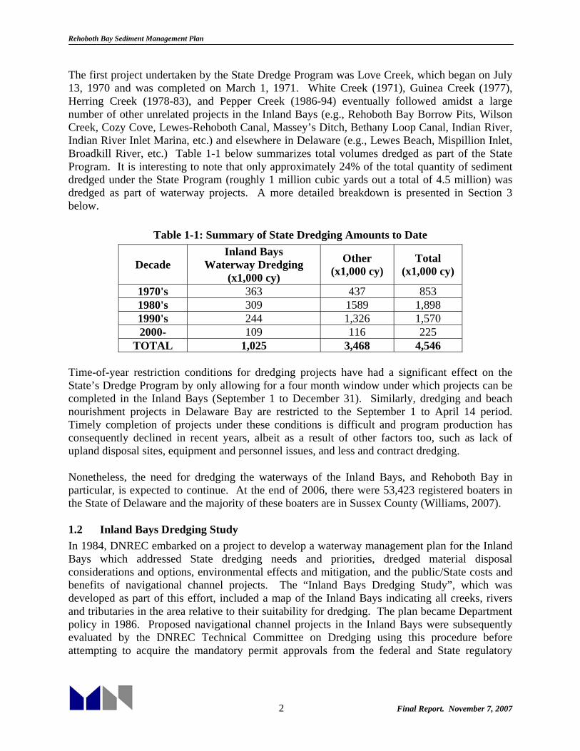
The first project undertaken by the State Dredge Program was Love Creek, which began on July 13, 1970 and was completed on March 1, 1971. White Creek (1971), Guinea Creek (1977), Herring Creek (1978-83), and Pepper Creek (1986-94) eventually followed amidst a large number of other unrelated projects in the Inland Bays (e.g., Rehoboth Bay Borrow Pits, Wilson Creek, Cozy Cove, Lewes-Rehoboth Canal, Massey’s Ditch, Bethany Loop Canal, Indian River, Indian River Inlet Marina, etc.) and elsewhere in Delaware (e.g., Lewes Beach, Mispillion Inlet, Broadkill River, etc.) Table 1-1 below summarizes total volumes dredged as part of the State Program. It is interesting to note that only approximately 24% of the total quantity of sediment dredged under the State Program (roughly 1 million cubic yards out a total of 4.5 million) was dredged as part of waterway projects. A more detailed breakdown is presented in Section 3 below.
Table 1-1: Summary of State Dredging Amounts to Date
Decade Inland Bays
Waterway Dredging (x1,000 cy)
Other (x1,000 cy)
Total (x1,000 cy)
1970's 363 437 853 1980's 309 1589 1,898 1990's 244 1,326 1,570 2000- 109 116 225
TOTAL 1,025 3,468 4,546 Time-of-year restriction conditions for dredging projects have had a significant effect on the State’s Dredge Program by only allowing for a four month window under which projects can be completed in the Inland Bays (September 1 to December 31). Similarly, dredging and beach nourishment projects in Delaware Bay are restricted to the September 1 to April 14 period. Timely completion of projects under these conditions is difficult and program production has consequently declined in recent years, albeit as a result of other factors too, such as lack of upland disposal sites, equipment and personnel issues, and less and contract dredging. Nonetheless, the need for dredging the waterways of the Inland Bays, and Rehoboth Bay in particular, is expected to continue. At the end of 2006, there were 53,423 registered boaters in the State of Delaware and the majority of these boaters are in Sussex County (Williams, 2007). 1.2 Inland Bays Dredging Study In 1984, DNREC embarked on a project to develop a waterway management plan for the Inland Bays which addressed State dredging needs and priorities, dredged material disposal considerations and options, environmental effects and mitigation, and the public/State costs and benefits of navigational channel projects. The “Inland Bays Dredging Study”, which was developed as part of this effort, included a map of the Inland Bays indicating all creeks, rivers and tributaries in the area relative to their suitability for dredging. The plan became Department policy in 1986. Proposed navigational channel projects in the Inland Bays were subsequently evaluated by the DNREC Technical Committee on Dredging using this procedure before attempting to acquire the mandatory permit approvals from the federal and State regulatory

Rehoboth Bay Sediment Management Plan
3 Final Report. November 7, 2007
agencies involved in the permitting process. The Committee was comprised of personnel from the Divisions of Fish and Wildlife, Soil and Water Conservation and Water Resources. The study was revised in 2002 to ensure that the most current aquatic habitat and living resource assessment methods will be used and that dredging projects reflect the best dredging technologies and methods to minimize adverse impacts. The revised Study included criteria specifically designed for assessing the impacts associated with dredging private ancillary channels in creeks, rivers and tributaries in the Bays. It also included an updated look at dredged material disposal alternatives (i.e., beneficial uses of dredged material) and design guidelines and provided suggestions on where they might be implemented in the Inland Bays. A new guidance document, “Methodology for Evaluation of Proposed Dredging Projects in Delaware’s Inland Bays”, was completed in October 2002. 1.3 State Channel Marking Program The Shoreline and Waterway Management Section began placing navigational channel markers (aids to navigation) in the State’s Inland Bays in 1996 (Williams, 2007). As part of its initial State permit approval to dredge the Assawoman Canal, the Section agreed to mark a channel in the Little Assawoman Bay that year. The effort was designed to locate a channel in the Bay to ensure safe navigation for the boating public. A secondary purpose was to centralize boating traffic in the water body to the extent possible and keep boaters away from environmentally sensitive areas (e.g. shallow water habitats, wetlands). The Division eventually entered into a cooperative agreement with the U. S. Coast Guard in 2001 to establish aids to navigation in the State’s Inland Bays in waterways that the Coast Guard does not mark. The creeks/bays and the number of markers the Section is responsible for maintaining in each as of August 2007 is presented below:
Love Creek – 20 daybeacons Massey’s Ditch/downstream Indian River – None at this present time. Will re-establish as needed in cooperation with U.S. Coast Guard Herring Creek – 21 daybeacons Indian River – (Conectiv Power Plant to Cupola Parkin Millsboro) – 36 daybeacons Pepper Creek – 6 daybeacons White Creek – 8 daybeacons Beach Cove/Indian River Bay – 13 daybeacons Little Assawoman Bay - 30 daybeacons Roy Creek – 20 daybeacons Total: 154 daybeacons
1.4 Macroalgae Harvesting Program Increasing eutrophication in the State’s Inland Bays has led to extensive growth of both red and green seaweed (i.e., macroalgae). This has caused a number of problems, most notably, the seasonal accumulation of windrows of dead and dying macroalgae in shallow waters of the Bays with attendant complaints concerning obnoxious odors and nuisance build-ups of deteriorating algae along the shorelines. In response to these complaints and to requests from members of the General Assembly, the Division implemented a program in 1997 to harvest noxious

Rehoboth Bay Sediment Management Plan
4 Final Report. November 7, 2007
accumulations near waterfront communities (Williams, 2007). Over the next few years harvesting equipment and operations were optimized and concerns regarding the potential detrimental effects of harvesting were mostly addressed. In 2005, the most productive year since harvesting begun in 1997, the harvesters worked a total of 54 days during the spring, summer and fall and harvested approximately 285 tons of algae from the following locations 1.5 Present Funding Over the years, the Dredge Program has received both General Fund and Bond Bill appropriations from the State Legislature for general operations and specific projects. In addition, legislative appropriations have been given to the program for the purchase of new dredges in FY1982 ($225,000), FY1986 ($720,000) and FY2005 ($650,000). In FY2004, the budget for the State Dredge Program was approximately $755,000, which includes employee salaries, money for supplies and materials and contractual services, and funding for the New Castle Conservation District Dredge Program (Williams, 2007). The Division does not currently have funding dedicated to perform macroalgae harvesting and channel marking operations. Money used to support these activities (e.g. fuel, equipment maintenance) comes from the Dredge Program budget. Estimated costs for harvesting efforts are approximately $50,000 annually, including staff time and resources. Approximately $30,000 will be needed annually to effectively mark channels in the Inland Bays.

Rehoboth Bay Sediment Management Plan
5 Final Report. November 7, 2007
2. EXISTING CONDITIONS The first phase of this study was an Existing Conditions Assessment, which is detailed in this Section. The assessment included collection of environmental data and sediment characteristic data as well as examination of historical dredging and disposal practices. 2.1 Study Area Rehoboth Bay is part of Delaware’s Inland Bays which encompass Rehoboth Bay, Little Assawoman Bay, and Indian River Bay. Both Rehoboth Bay and Little Assawoman Bay are bar-built estuaries, while Indian River Bay is a drowned river valley. Rehoboth Bay is the northernmost of Delaware’s inland bays (Figure 2-1). Depths in the bay are generally shallow, less than 6 to 7 feet below Mean Lower Low Water (MLLW). Surface area of the bay is approximately 13 square miles. Rehoboth Bay receives fresh water discharges from a number of small creeks along the bay, including White Oak Creek, Love Creek, Herring Creek, and Guinea Creek. Rehoboth Bay is linked to Indian River Bay to the south, providing tidal exchange with the Atlantic Ocean through Indian River Inlet, which is stabilized by two parallel stone jetties. To the north, the Lewes-Rehoboth Canal provides limited exchange with Delaware Bay.
Figure 2-1. Study Area Location Map

Rehoboth Bay Sediment Management Plan
6 Final Report. November 7, 2007
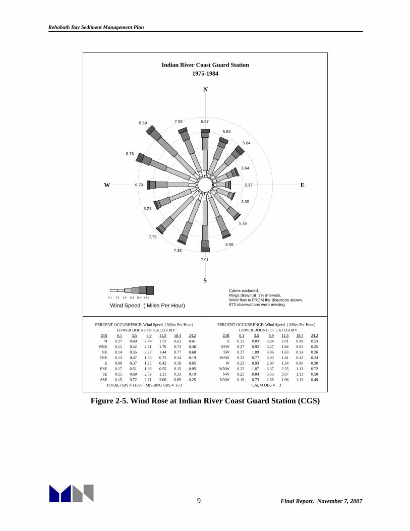
Since the inception of DNREC’s dredging program in 1970, six primary channel dredging projects have been completed within Rehoboth Bay: the Lewes-Rehoboth Canal, Love Creek, Herring Creek, Guinea Creek, Wilson Creek, and Massey’s Ditch. A number of previous hydrodynamic, water quality, and sediment studies have been conducted focusing on the Inland Bays. DNREC funded a water quality and hydrodynamic model study in 2002-2003 focusing on Total Maximum Daily Load (TMDL) computations, which provided information that will be used in the present study (Kolluru and Fichera, 2003). The US Army Corps of Engineers (USACE) conducted an extensive hydrodynamic model study in the early 1990s, also providing valuable data (Cerco et al., 1991). Several studies conducted at the University of Delaware also provide insight into erosion, sediment characteristics, and tides and currents in the bays (Wong, 1988, 1994). A summary of previous studies reviewed for this report is provided in Appendix A. 2.2 Environmental Conditions Data were collected describing the winds, water levels, currents, bathymetry, and historic erosion within the bay, and are described in this section. A number of available data sources were compiled for this study. Data source locations are shown on Figure 2-2. An overall summary of the data collected for this project is found in Appendix B. 2.2.1 Winds Wind data were obtained from the National Climactic Data Center (NCDC) at three locations in relatively close proximity to Rehoboth Bay. Wind sources are shown in Figure 2-3. The closest data station is the Indian River Inlet Coast Guard Station (CGS). However, this site does not have a complete data record after approximately the mid eighties. Data for this station were obtained for the 1975 to 1984 time period, to provide historical insight into the winds near the project area. These data were also compared with data obtained from 2000 to 2006 at Dover Air Force Base (AFB) and from 1997 to 2006 at the Georgetown-Sussex Airport. Dover AFB is located approximately 35 miles north northwest of Rehoboth Bay; the Georgetown-Sussex Airport is approximately 15 miles west of the bay. Daily wind conditions at all locations generally range from 5 to 20 miles per hour, as shown in Figure 2-4. Wind speeds at the Indian River Coast Guard Station were slightly higher overall than those at the Dover AFB and Georgetown-Sussex Airport, likely due to that site’s exposed location at the coastline. The Georgetown-Sussex Airport data show the lowest overall wind speeds, likely due to the more sheltered inland location of the site. Figure 2-5 shows an overall wind rose for all data available from 1975 to 1984 at the Indian River Coast Guard Station. Figure 2-6 illustrates the seasonality of wind direction at the station. Figure 2-7 and Figure 2-8 show similar data for the Dover AFB, and Figure 2-9 and Figure 2-10 illustrate the wind roses for Georgetown-Sussex airport. As shown on the figures, overall winds in the region prevail from the westerly quadrants. In winter, prevailing winds are from the northwest, while during spring, winds have a relatively uniform directional distribution. Summertime winds are mainly from the southwest, bringing warm air to the region. Fall winds from the westerly quadrants are most common, with occasional nor’easter storms. All three locations show similar patterns of seasonality.

Rehoboth Bay Sediment Management Plan
7 Final Report. November 7, 2007
Figure 2-2. Locations of Environmental Data Sources

Rehoboth Bay Sediment Management Plan
8 Final Report. November 7, 2007
Figure 2-3. Location of Wind Data Sources
0%
10%
20%
30%
40%
50%
60%
70%
80%
90%
100%
0 5 10 15 20 25 30 35 40 45 50 55
Wind Speed (MPH)
Perc
ent E
xcee
danc
e
Indian River CGS
Dover AFB
Georgetown-Sussex Airport
Figure 2-4. Percent Exceedance Curves for Wind Speeds
Rehoboth Bay Sediment Management Plan
9 Final Report. November 7, 2007
Indian River Coast Guard Station1975-1984
N
S
W E
673 observations were missing.Wind flow is FROM the directions shown.Rings drawn at 2% intervals.Calms excluded.
6.37
5.63
5.84
3.64
2.37
3.09
5.16
6.55
7.91
7.38
7.75
6.21
6.70
8.76
9.59 7.08
Wind Speed ( Miles Per Hour)0.1 3.5 6.9 11.5 18.4 24.2
PERCENT OCCURRENCE: Wind Speed ( Miles Per Hour) LOWER BOUND OF CATEGORY
DIR 0.1 3.5 6.9 11.5 18.4 24.2N
NNENE
ENEE
ESESE
SSE
0.27 0.11 0.14 0.13 0.09 0.17 0.15 0.15
0.60 0.42 0.55 0.47 0.37 0.51 0.68 0.72
2.74 2.21 2.27 1.56 1.25 1.66 2.59 2.71
1.72 1.70 1.44 0.75 0.42 0.55 1.31 2.06
0.63 0.73 0.77 0.54 0.19 0.15 0.33 0.65
0.41 0.46 0.68 0.19 0.05 0.05 0.10 0.25
PERCENT OCCURRENCE: Wind Speed ( Miles Per Hour) LOWER BOUND OF CATEGORY
DIR 0.1 3.5 6.9 11.5 18.4 24.2S
SSWSW
WSWW
WNWNW
NNW
0.33 0.27 0.27 0.33 0.23 0.22 0.25 0.19
0.83 0.92 1.09 0.77 0.93 1.07 0.84 0.73
3.24 3.27 3.96 3.05 2.90 3.37 3.53 2.58
2.01 1.84 1.63 1.41 1.54 2.25 3.07 1.96
0.98 0.83 0.54 0.42 0.80 1.13 1.33 1.13
0.53 0.25 0.26 0.24 0.30 0.72 0.58 0.49
TOTAL OBS = 11687 MISSING OBS = 673 CALM OBS = 3
Figure 2-5. Wind Rose at Indian River Coast Guard Station (CGS)

Rehoboth Bay Sediment Management Plan
10 Final Report. November 7, 2007
Figure 2-6. Seasonal Wind Roses at Indian River CGS

Rehoboth Bay Sediment Management Plan
11 Final Report. November 7, 2007
Dover Air Force Base2000-2006
N
S
W E
7159 observations were missing.Wind flow is FROM the directions shown.Rings drawn at 5% intervals.Calms excluded.
7.86
4.02
3.66
3.92
5.19
4.36
4.81 4.01
7.89 8.31
7.77
6.55
10.62
8.02
8.08 6.59
Wind Speed ( Miles Per Hour)0.1 3.5 6.9 11.5 18.4 24.2
PERCENT OCCURRENCE: Wind Speed ( Miles Per Hour) LOWER BOUND OF CATEGORY
DIR 0.1 3.5 6.9 11.5 18.4 24.2N
NNENE
ENEE
ESESE
SSE
0.56 0.47 0.34 0.27 0.48 0.48 0.69 0.76
1.50 0.71 0.57 0.54 0.85 0.96 1.25 1.40
3.56 1.86 1.68 1.78 2.74 2.39 2.49 1.62
1.82 0.90 0.90 1.00 0.92 0.51 0.33 0.18
0.36 0.07 0.14 0.27 0.16 0.02 0.05 0.03
0.06 0.01 0.02 0.06 0.04 0.01 0.01 0.02
PERCENT OCCURRENCE: Wind Speed ( Miles Per Hour) LOWER BOUND OF CATEGORY
DIR 0.1 3.5 6.9 11.5 18.4 24.2S
SSWSW
WSWW
WNWNW
NNW
1.14 0.66 0.63 0.56 0.59 0.35 0.38 0.39
2.37 1.58 1.52 1.32 1.57 0.69 0.86 1.01
3.23 4.03 3.81 3.35 5.04 3.05 3.24 2.82
0.97 1.64 1.51 1.12 2.64 2.53 2.39 1.82
0.14 0.32 0.21 0.16 0.60 1.13 0.87 0.46
0.02 0.09 0.08 0.04 0.17 0.27 0.34 0.09
TOTAL OBS = 57548 MISSING OBS = 7159 CALM OBS = 935
Figure 2-7. Wind Rose at Dover Air Force Base (AFB)

Rehoboth Bay Sediment Management Plan
12 Final Report. November 7, 2007
Figure 2-8. Seasonal Wind Roses at Dover AFB

Rehoboth Bay Sediment Management Plan
13 Final Report. November 7, 2007
Figure 2-9. Wind Rose at Georgetown-Sussex Airport

Rehoboth Bay Sediment Management Plan
14 Final Report. November 7, 2007
Figure 2-10. Seasonal Wind Roses at Georgetown-Sussex Airport

Rehoboth Bay Sediment Management Plan
15 Final Report. November 7, 2007
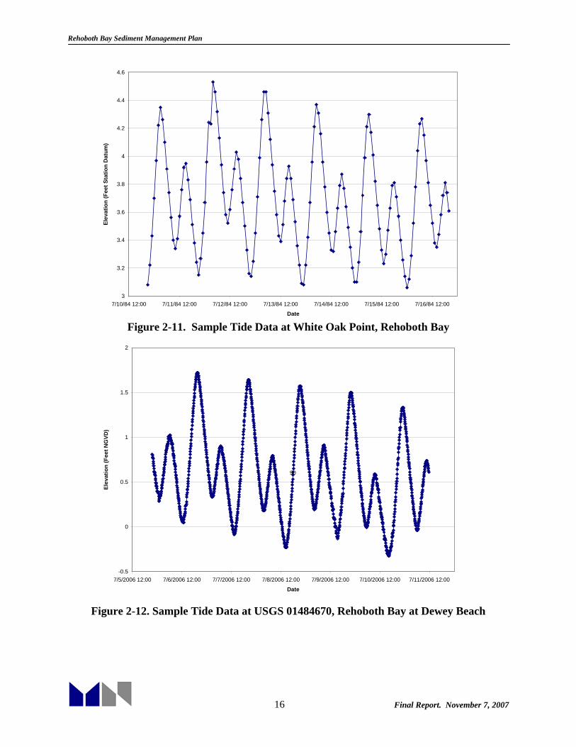
2.2.2 Water Levels Water levels within the Inland Bays are primarily driven by tidal fluctuation. Tides within the Inland Bays are primarily driven by flow entering through Indian River Inlet. Due to the increases in cross-sectional area and depth of the inlet since the stabilization of Indian River Inlet in 1939, the tidal wave propagating through the inlet has increased. This caused an enlargement of the tidal range within the bays (Raney et al., 1991). Tidal prism has also increased by 4.5 times at Indian River Inlet and 3.8 times entering Rehoboth Bay between 1939 and 1988. Tidal information for the Delaware Inland Bays is available from the National Oceanographic and Atmospheric Administration (NOAA) as well as the US Geological Survey (USGS). The closest NOAA tide gauge currently collecting data is in Lewes, approximately seven miles north of Rehoboth Bay. This area exchanges water with Rehoboth Bay via the Lewes-Rehoboth Canal. Hourly tide data are available for the Lewes gauge dating from 1957 to the present. In addition, historic hourly tide data are available at Indian River Inlet from 1977 to 1986. A very limited tide gauge deployment was conducted at White Oak Point within Rehoboth Bay, from July 10, 1984 to July 16, 1984. Hourly tide data are available from that deployment as well. Water level data are also available at the USGS Rehoboth Bay at Dewey Beach, from 1985 to 1997 and October 2000 to the present. A limited gauge deployment was conducted by the USGS at Massey’s Ditch from October 1, 1991 to September 30, 1993. Data were also available at the Rosedale Beach Station from April 1991 through the present. Tides at Lewes, Indian River Inlet and within the Inland Bays are semidiurnal, with two low and two high tides daily. Typical water level records are shown in Figure 2-11, Figure 2-12 and Figure 2-13. Tidal datums have been computed by NOAA for both the Lewes and Indian River Inlet stations. These datums are presented in Table 2-1. As shown in these tables, the mean tide range at Lewes is approximately 4 feet and is approximately 2.5 feet at Indian River Inlet. At the locations within Rehoboth Bay, the tide range is on the order of 1.5 feet. Datum elevations at Lewes have been controlled relative to both the National Geodetic Vertical Datum of 1929 (NGVD) and the North American Vertical Datum (NAVD); at Indian River Inlet, control exists only for NGVD. Tidal datums are periodically adjusted to reflect changes in average sea level along the coast. The new datums provide updated information for a new National Tidal Datum Epoch (NTDE), which is a specific 19-year period over which tide observations are taken to determine average sea level and other water level information. The tidal datums listed in Table 2-1 are based on the most recent 1983-2001 Epoch.
Rehoboth Bay Sediment Management Plan
16 Final Report. November 7, 2007
3
3.2
3.4
3.6
3.8
4
4.2
4.4
4.6
7/10/84 12:00 7/11/84 12:00 7/12/84 12:00 7/13/84 12:00 7/14/84 12:00 7/15/84 12:00 7/16/84 12:00
Date
Elev
atio
n (F
eet S
tatio
n D
atum
)
Figure 2-11. Sample Tide Data at White Oak Point, Rehoboth Bay
-0.5
0
0.5
1
1.5
2
7/5/2006 12:00 7/6/2006 12:00 7/7/2006 12:00 7/8/2006 12:00 7/9/2006 12:00 7/10/2006 12:00 7/11/2006 12:00
Date
Elev
atio
n (F
eet N
GVD
)
90
Figure 2-12. Sample Tide Data at USGS 01484670, Rehoboth Bay at Dewey Beach

Rehoboth Bay Sediment Management Plan
17 Final Report. November 7, 2007
-1
-0.5
0
0.5
1
1.5
2
5/13/92 12:00 5/14/92 12:00 5/15/92 12:00 5/16/92 12:00 5/17/92 12:00 5/18/92 12:00 5/19/92 12:00
Date
Elev
atio
n (F
eet N
GVD
)
Figure 2-13. Sample Tide Data at USGS Massey’s Ditch Gauge
Table 2-1. Tidal Datums at Lewes, DE and Indian River Inlet, DE
Tidal Datum Lewes (ft)
Indian River Inlet (ft)
Mean Higher High Water (MHHW) 4.65 2.94 Mean High Water (MHW) 4.23 2.67 North American Vertical Datum-1988 (NAVD)
2.63 1.82
Mean Sea Level (MSL) 2.23 1.48 Mean Tide Level (MTL) 2.19 1.41 National Geodetic Vertical Datum-1929 (NGVD)
1.87 1.05
Mean Low Water (MLW) 0.16 0.15 Mean Lower Low Water (MLLW) 0.00 0.00
2.2.3 Currents Current measurements have been reported by a number of different researchers. Wong (1988) measured tidal currents at Indian River Inlet and the southern entrance to Massey’s Ditch. Strong tidal currents with amplitudes on the order of 4.9 ft/s were observed at Indian River Inlet. At Massey’s Ditch, current amplitudes were appreciably lower, on the order of 2 ft/s. In a later paper, Wong and Lu (1994) studied subtidal variability, with deployment of six current meters: two across Indian River Inlet, two across Massey’s Ditch, and two along the northern and southern reaches of the Lewes-Rehoboth Canal. Observed currents in the channels showed

Rehoboth Bay Sediment Management Plan
18 Final Report. November 7, 2007
considerable subtidal fluctuations in excess of 0.8 ft/s. Most of the subtidal variability was attributed to coastal sea level fluctuations. At long time scales (longer than 1 week), a two-layer circulation pattern was found with a surface outflow and bottom inflow, consistent with density induced gravitational circulation. Wong also measured currents for the DNREC-funded TMDL study in 2002 (Kolluru and Fichera, 2003), and the unpublished current data were obtained from DNREC. Currents were measured from April 2002 to July 2002 at Indian River Inlet (3 locations near the top, middle and bottom of the water column), Indian River Bay, and Rehoboth Bay. Four locations within Little Assawoman Bay were also monitored but are not included in this study. Tidal amplitudes recorded within Indian River Inlet were consistent with previous measurements, with east-west currents measured at the middle of the water column showing amplitudes on the order of 4.9 ft/sec. Amplitudes near the bottom of the water column were slightly smaller, approximately 3.9 ft/sec, and near the top of the water column amplitudes were slightly higher, approximately 5.6 ft/sec. In Rehoboth Bay, north-south currents were slightly dominant with amplitudes on the order of 0.3 ft/sec; east-west amplitudes were on the order of 0.2 ft/sec. East-west currents dominated at the Indian River Bay gauge with amplitudes on the order of 0.8 ft/sec; north-south current amplitudes were found to be on the order of 0.3 ft/sec. Raney et al. (1990) employed current data collected from June 29 through July 1, 1988 in calibration of the hydrodynamic model of the Indian River Bay – Rehoboth Bay system. Current data were collected at three stations across Indian River Inlet and two each at Big Ditch and Little Ditch adjacent to Middle Island. Current amplitudes measured across the inlet ranged from approximately 4 ft/sec to 8 ft/sec over the short measurement time period, consistent with other reported values. Little Ditch and Big Ditch current amplitudes ranged from approximately 2 ft/sec to 3 ft/sec, similar to the values reported at Massey’s Ditch by Wong (1988). All previous studies indicate strong tidal currents through Indian River Inlet, with appreciably reduced values at the exchange between Indian River Bay and Rehoboth Bay. Tidal currents within the open expanse of Rehoboth and Indian River Bays were relatively weak. Further investigation of tidal currents and hydrodynamics of the Indian River Bay-Rehoboth Bay system will be completed as part of the hydrodynamic modeling task for this study. 2.2.4 Bathymetry Bathymetry in the study area is available from DNREC, the Army Corps of Engineers, and the National Geophysical Data Center (NGDC)’s Geophysical Database (GEODAS). Specific surveys available are listed in Table 2-2 along with the general areas for which they were the primary bathymetry source. The surveys performed by the Army Corps of Engineers consisted of a Multibeam and Singlebeam survey of the inlet. Theses surveys are described in the final report from Ocean Surveys, Inc to the Army Corps of Engineers (OSI Report #04ES090A).

Rehoboth Bay Sediment Management Plan
19 Final Report. November 7, 2007
Table 2-2. Bathymetric Data Sources
Date Coverage Source 2004 IR Inlet and Surrounding areas USACE 2004 Inland Bays DNREC 1863,1970,1977, 1984 Offshore NGDC (GEODAS) 2004 Love Creek DNREC 2004 Herring Creek DNREC 1998 Guinea Creek DNREC 2000 Bald Eagle Creek DNREC 2005 Roosevelt Inlet (Lewes
Rehoboth Canal) USACE
DNREC conducted a detailed survey of the Inland Bays in 2004. This survey encompassed most of Indian River Bay and Rehoboth Bay. The resolution was sufficient for critical areas such as Massey’s Ditch. In addition, four surveys of creeks adjacent to Rehoboth Bay were surveyed by DNREC ranging in time from 1998 through 2004. Figure 2-14 through Figure 2-18 show the sources of bathymetry available for the entire project area.
Figure 2-14. Bathymetry (NAVD88) obtained from DNREC (2004)

Rehoboth Bay Sediment Management Plan
20 Final Report. November 7, 2007
Figure 2-15. Bathymetry (NAVD88) obtained from USACE (2004)
Figure 2-16. Bathymetry (MLW) obtained from NGDC (GEODAS-1963, 1970, 1977, 1984)

Rehoboth Bay Sediment Management Plan
21 Final Report. November 7, 2007
Figure 2-17. Bathymetry (MLW) for Creeks off of Rehoboth Bay
Figure 2-18. Bathymetry (MLW) for the Lewes Rehoboth Canal

Rehoboth Bay Sediment Management Plan
22 Final Report. November 7, 2007
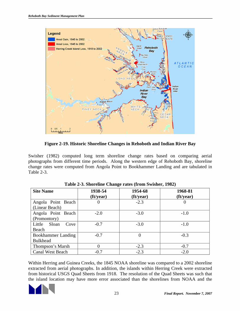
2.2.5 Historical Shoreline Change Data on long term and short term historical shoreline changes within Rehoboth Bay were assembled to investigate areas of potential marsh erosion/marsh loss. These areas may later be identified for potential beneficial use of dredged material in marsh restoration. Short-Term Shoreline Change Schwimmer (2001) conducted surveys of the marsh shoreline in western Rehoboth Bay over a period of three years. Survey sites included five locations in Horse Island Marsh and included one location on Marsh Island (Figure 2-19). Measured shoreline recession rates on a yearly basis ranged from 9 ± 4 cm/year (0.3 ± 0.1 ft/year) to 52 ± 4 cm/year (1.7 ± 0.1 ft/year). The greatest average rate of erosion over the entire three-year period was 43 ± 4 cm/year (1.4 ± 0.1 ft/year) on Marsh Island. Swisher (1982) assessed short-term erosion within Rehoboth Bay, with a focus on 15 sites on the northern, western, and southern bay shorelines. From August 1981 to May 1982 sites were monitored approximately every month to determine volumetric changes in profiles taken perpendicular to the shoreline. The net change between survey dates and cumulative change for the entire study period were calculated. The largest cumulative changes in profile area ranged from -11.3 m2 along the southern shoreline to +4.8 m2 along the northwest shoreline. Ten of the fifteen sites experienced a negative cumulative change over the study period. Long-Term Shoreline Change Swisher (1982) also assessed long-term shoreline change using four sets of aerial photography ranging from 1938 to 1981. The shoreline was divided into 68 sections from which average linear erosion rates were calculated between shoreline positions of consecutive years. The results indicated that the long term trends in shoreline change are extremely variable ranging from -9.5 m/yr to +13.8 m/yr. The average change rates for the entire northern shoreline ranged from -0.3 m/yr to +1.1 m/yr. The average rates for the western and southern shoreline ranged from -0.4 m/yr to -0.6 m/yr and -0.1 m/yr to -0.2 m/yr respectively. In general, most areas of the bay have been experiencing net erosion rates of -1 m/yr or less. As part of this task M&N also compared historical shorelines available from NOAA with a shoreline from recent (2002) aerial photographs to provide a general assessment of long-term shoreline changes within Rehoboth Bay. Figure 2-19 shows areas of significant shoreline erosion within the bay from 1845 to 2002. Islands within Herring Creek were compared from USGS Quad Sheets in 1918 with 2002 data.
Rehoboth Bay Sediment Management Plan
23 Final Report. November 7, 2007
Figure 2-19. Historic Shoreline Changes in Rehoboth and Indian River Bay Swisher (1982) computed long term shoreline change rates based on comparing aerial photographs from different time periods. Along the western edge of Rehoboth Bay, shoreline change rates were computed from Angola Point to Bookhammer Landing and are tabulated in Table 2-3.
Table 2-3. Shoreline Change rates (from Swisher, 1982) Site Name 1938-54
(ft/year) 1954-68 (ft/year)
1968-81 (ft/year)
Angola Point Beach (Linear Beach)
0 -2.3 0
Angola Point Beach (Promontory)
-2.0
-3.0 -1.0
Little Sloan Cove Beach
-0.7 -3.0 -1.0
Bookhammer Landing Bulkhead
-0.7 0 -0.3
Thompson’s Marsh 0 -2.3 -0.7 Canal West Beach -0.7 -2.3 -2.0
Within Herring and Guinea Creeks, the 1845 NOAA shoreline was compared to a 2002 shoreline extracted from aerial photographs. In addition, the islands within Herring Creek were extracted from historical USGS Quad Sheets from 1918. The resolution of the Quad Sheets was such that the island location may have more error associated than the shorelines from NOAA and the

Rehoboth Bay Sediment Management Plan
24 Final Report. November 7, 2007
aerial photographs. Figure 2-20 shows the shoreline changes between 1845 and 2002. Migrations in channel location can be seen in the Burton Prong of Herring Creek (approximately 150 ft) and in Guinea Creek (approximately 250 ft). In addition, the banks of Herring Creek exhibit slight erosion with changes from 0 to almost 300 ft in some areas. Small islands within Herring Creek that were visible in 1918 are no longer visible in 2002. The large island towards the mouth of Herring Creek has almost entirely eroded with losses of almost 5 acres. Two marsh islands, Big Piney Island and Little Piney Island, completely disappeared between 1845 and 2002. Substantial loss of marsh has also occurred over the long term at Marsh Island and along the shoreline between Horse Island Marsh and Angola Point. These losses are shown in Figure 2-21. Along this western shoreline of Rehoboth Bay, the orientation and fetch increase its vulnerability to storm erosion. Swisher (1982) found that the largest changes in this area occurred between 1954 and 1968, which could have been due to the 1962 storm. Looking at the erosion of Marsh Island in Figure 2-21, it is seen that the majority of erosion is found along the northeast and southeast shorelines. Along the north-eastern side of Marsh Island, almost 400 feet of land was lost from 1845 to 2002, and along the south-eastern side, almost 200 ft were lost. Total marsh area lost at Marsh Island was 6.28 acres. At Big Piney Island 8.79 acres were lost, and at Little Piney Island 3.31 acres were lost. Looking at long term erosion rates, the erosion rate on the exposed islands such as Marsh Island and Big Piney Island, was calculated to be about 2.3 ft/year or higher, which corresponds to findings computed by Swisher (1982). More protected regions, like the areas behind the islands, and more recessed land areas have lower erosion rates or even gain land.
Figure 2-20. Historic Shoreline Changes in the vicinity of Herring Creek and Guinea Creek

Rehoboth Bay Sediment Management Plan
25 Final Report. November 7, 2007
Figure 2-21. Historic Shoreline Changes in the vicinity of Big Piney Island
The addition of the jetty structures at the end of the Lewes-Rehoboth Canal in 1903 affected the shoreline in the area. Figure 2-22 shows the accretion immediately updrift of the jetty. However, the overall trend of the area is erosional, and further updrift of the jetty, the shoreline still eroded. Swisher (1982) reports that the updrift accretion is spilling over the jetty and into the canal, and a breach in the downdrift jetty is allowing some sediment through to the downdrift side, which causes the slight cuspate immediately downdrift of the western jetty. Erosion on the downdrift is higher than occurs on the updrift side, since some of the sediment that would be expected to drift down the shoreline is being stopped by the jetty in place. At its widest point the erosion of the downdrift side reaches almost 450 ft from the 1845 shoreline. Updrift of the jetties, the widest point is only 145 ft from the 1845 shoreline. On the downdrift side, it was computed that approximately 14.34 acres were lost between the 1845 shoreline and the 2002 shoreline. Table 2-3 shows that this difference in erosion rates is most pronounced in the time period from 1968 to 1982, where the erosion rate downdrift at Canal West Beach was -2.0 ft/year, while the rate updrift of the jetties was only -0.7 ft/year.

Rehoboth Bay Sediment Management Plan
26 Final Report. November 7, 2007
Figure 2-22. Historic Shoreline Changes in the vicinity of Thompson’s Island
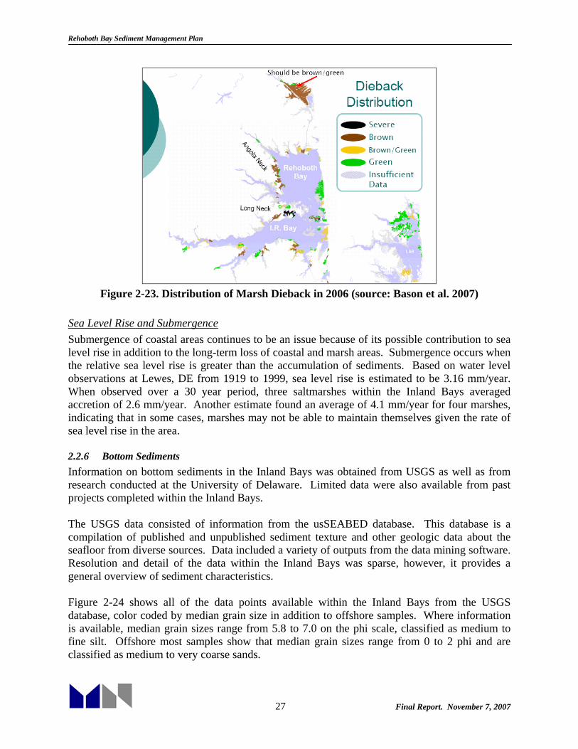
Sudden Marsh Dieback (from Bason et al. 2007) When rapid death or failure of saltmarsh vegetation to grow occurs, it is characterized as Sudden Wetland or Marsh Dieback. The cause of this phenomenon is not definitively known, however several theories have been presented. Suggested causes include consumption by saltmarsh snails or grasshoppers. In addition, an explanation by McKee et al. (2004) shows that a severe drought caused a marsh water deficit which was followed by an acidification of the soil through sulfuric acid production. Sudden Marsh Dieback was first observed within the Delaware Inland Bays in the summer of 2006 (Figure 2-23). It was mostly noticed within the interior of the marshes with shorelines and ditch edges continuing to support healthy marsh grasses. Within the monitoring effort conducted in September 2006, 41% of the observed marshes (22%) exhibited signs of dieback, mostly in Indian River and Rehoboth Bays. Moderate droughts occurring in 2006 in combination with the seasonal and tidal sulphur cycles could have combined to cause the stressful conditions documented in Louisiana by McKee et al. (2004). This cause is not proven, and would require more testing and investigation. Due to the economic, social, and environmental importance of the saltmarshes within the Inland Bays, understanding sudden marsh dieback is imperative. Saltmarshes protect coastal development land from erosion and storm surges in addition to their importance as habitats for coastal life. Due to the fact that approximately 24% of Inland Bays wetland area has already been lost due to development between 1938 and 1973, the remaining marsh areas are critical.
Rehoboth Bay Sediment Management Plan
27 Final Report. November 7, 2007
Figure 2-23. Distribution of Marsh Dieback in 2006 (source: Bason et al. 2007)
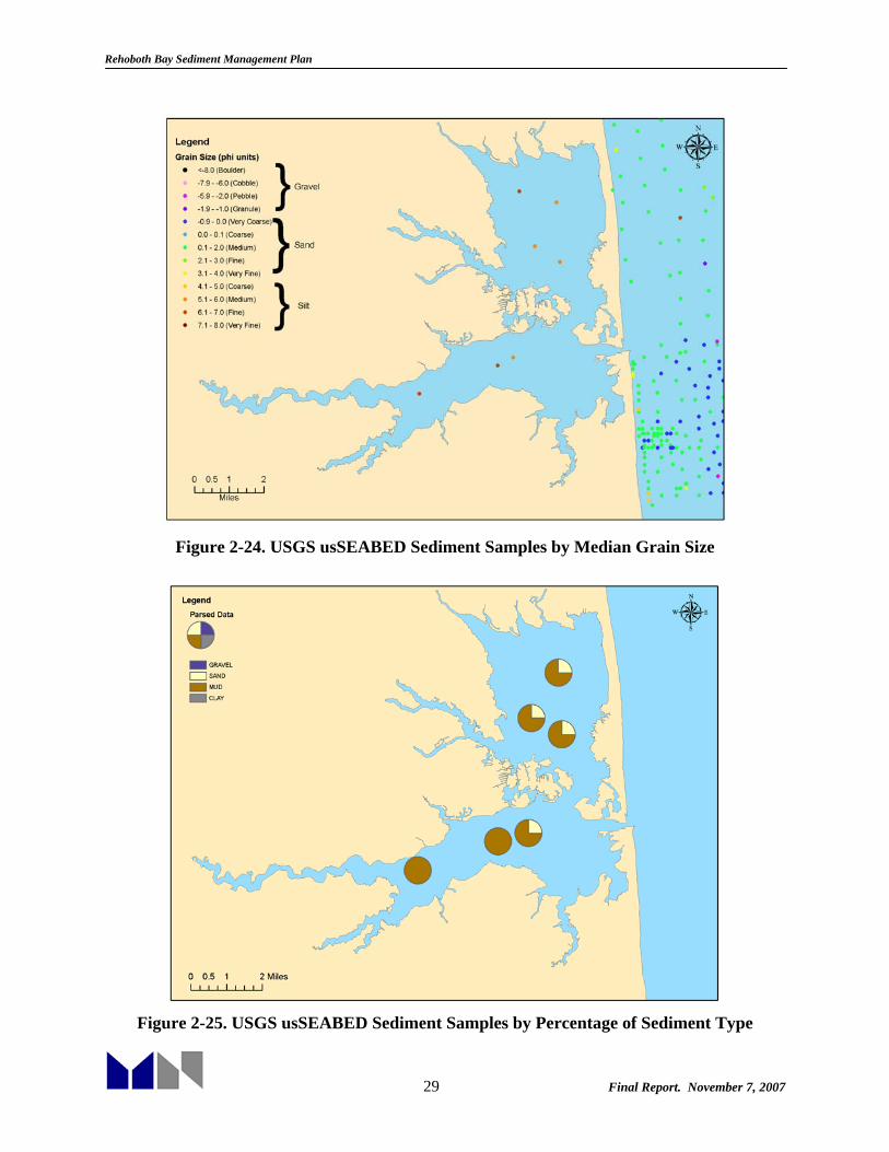
Sea Level Rise and Submergence Submergence of coastal areas continues to be an issue because of its possible contribution to sea level rise in addition to the long-term loss of coastal and marsh areas. Submergence occurs when the relative sea level rise is greater than the accumulation of sediments. Based on water level observations at Lewes, DE from 1919 to 1999, sea level rise is estimated to be 3.16 mm/year. When observed over a 30 year period, three saltmarshes within the Inland Bays averaged accretion of 2.6 mm/year. Another estimate found an average of 4.1 mm/year for four marshes, indicating that in some cases, marshes may not be able to maintain themselves given the rate of sea level rise in the area. 2.2.6 Bottom Sediments Information on bottom sediments in the Inland Bays was obtained from USGS as well as from research conducted at the University of Delaware. Limited data were also available from past projects completed within the Inland Bays. The USGS data consisted of information from the usSEABED database. This database is a compilation of published and unpublished sediment texture and other geologic data about the seafloor from diverse sources. Data included a variety of outputs from the data mining software. Resolution and detail of the data within the Inland Bays was sparse, however, it provides a general overview of sediment characteristics. Figure 2-24 shows all of the data points available within the Inland Bays from the USGS database, color coded by median grain size in addition to offshore samples. Where information is available, median grain sizes range from 5.8 to 7.0 on the phi scale, classified as medium to fine silt. Offshore most samples show that median grain sizes range from 0 to 2 phi and are classified as medium to very coarse sands.

Rehoboth Bay Sediment Management Plan
28 Final Report. November 7, 2007
At a percentage of the points, information was available classifying the sample by percentage of gravel, sand, mud and clay. These data are shown in Figure 2-25. The Rehoboth Bay samples were classified as primarily mud with approximately 25 percent sand. In Indian River Bay, the western samples were mud, with sand found in the easternmost sample closest to Indian River Inlet. More detailed information was obtained from research conducted by Chrzastowski (1986). Chrzastowski examined recent (Holocene) sedimentary deposits and the geologic history of Rehoboth Bay and Indian River Bay based on 96 vibracores collected as part of his research and 181 core records from previous investigations. Ancestral river valleys at Love/Herring Creek and Indian River underlie deposits of tidal stream mud, marsh mud, flood tidal delta/barrier sand, and lagoonal mud. The sand and lagoonal mud deposits are a relatively thin cover to the sediments deposited in tidal streams and fringing salt marsh. Surficial samples indicated that fine sands are present in the eastern portions of the bays with a transition to silty sand, sandy silt, clayey silt and silty clay in the western portions of the bays and at the mouths of tributaries, as shown in Figure 2-26. Limited, project-specific sediment data were also available in permit documentation for individual projects. Within Indian River Bay, information was available for the Indian River channel, Pepper Creek, Vines Creek, White Creek and the Assawoman Canal. In general, the data agree with the findings of Chrzastowski (1986), with some areas showing more sand content than anticipated in the tributaries. The Indian River channel material dredged by the State was found to be primarily silt-clay and some silt-clay with minor sand. Toward the entrance of Indian River Inlet, sediment was found to be sand with some minor silt-clay while towards the central portion of the bay the sediment was found to be primarily silt-clay. Sediments within Pepper Creek were described as sandy loams and Holocene muds. In Vines Creek, one core sample reflected approximately 60% fine to coarse sand and 40% organic silt and clay. Shallow cores from the main channel of White Creek showed predominantly medium to coarse sand with less than ten percent organic material and silt/clay; within the west and east prongs, material was predominantly fine sand and silt-clay. Within Assawoman Canal, the material was found to be primarily sand, with organics, silts and clays found only in the southern portion of the canal. In Rehoboth Bay, previous project sediment data were available for Guinea Creek, Herring Creek, Bald Eagle Creek, the Lewes-Rehoboth Canal, and Massey’s Ditch. The Guinea Creek and Herring Creek projects, including Burton Prong and Hopkins Prong, had previously collected 13 core samples showing 5 to 7 ft of silt and approximately 1 ft of sand and clay at each location. Bald Eagle Creek soils were described as unconsolidated sedimentary muds and silt. Material in the Lewes-Rehoboth Canal was described as approximately 80 percent coarse to fine sand and 20 percent silt and clay. In Massey’s Ditch, sediments were primarily fine to medium sand with minute traces of silt and clay. The principal differences between the project specific data in Rehoboth Bay and the work by Chrzastowski (1986) occurred in the Lewes-Rehoboth Canal, where project data found a higher percentage of sands than indicated by Chrzastowski (1986).
Rehoboth Bay Sediment Management Plan
29 Final Report. November 7, 2007
Figure 2-24. USGS usSEABED Sediment Samples by Median Grain Size
Figure 2-25. USGS usSEABED Sediment Samples by Percentage of Sediment Type

Rehoboth Bay Sediment Management Plan
30 Final Report. November 7, 2007
Figure 2-26. Surficial Bottom Sediment Distribution (adapted from Chrzastowski, 1986)

Rehoboth Bay Sediment Management Plan
31 Final Report. November 7, 2007
3. HISTORICAL DREDGING AND DISPOSAL INVENTORY Both the US Army Corps of Engineers (USACE) and the State of Delaware have conducted dredging and disposal operations within Rehoboth Bay and Indian River Bay. Federally authorized channels exist within Rehoboth Bay at the Lewes-Rehoboth Canal inland waterway and at the waterway from Indian River Inlet to Rehoboth Bay (known as Massey’s Ditch). Additionally, the Indian River Inlet and Bay channel extending from Millsboro Bridge out through Indian River Inlet is a Federal channel and another authorized channel exists within Pepper Creek. The Federal Delmarva Intracoastal Waterway as authorized extended from Assawoman Canal up through Indian River and Rehoboth Bays and incorporated the Lewes-Rehoboth Canal and Massey’s Ditch projects. State projects have generally taken place in the tributaries of Rehoboth Bay, Indian River Bay, Little Assawoman Bay and at small harbor/marina facilities. Beach nourishment was performed updrift of Indian River Inlet prior to installation of a sand bypassing plant at the inlet in 1992. The state has performed maintenance work in the Federal channels as well. 3.1 USACE Dredging In recent years, the US Army Corps of Engineers has conducted very few dredging projects within Delaware’s Inland Bays. Within the past 10 years, the only project that has been maintained by USACE is the Roosevelt Inlet/Lewes-Rehoboth Canal project. Specifically, Roosevelt Inlet was dredged three times within the last 10 years: October 2004, January-February 2002, and October-November 1998. During the January-February 2002 operation dredging was also performed within the Lewes-Rehoboth Canal, when material was removed within the canal from Roosevelt Inlet to the Savannah Avenue Bridge (i.e., the northern portion of the canal). Although reports indicate that the canal had shoaled south of the bridge, lack of commercial traffic from that point to Rehoboth Bay has minimized the likelihood of Federal funding for channel maintenance. (Charlie Myers, USACE Project Manager, Pers Comm) More detailed discussion of this project is presented below. Historical data were also available from the Delmarva Intracoastal Waterway General Design Memorandum (GDM), Phase 1, dated December 1975. Recent dredging data were available from the USACE Navigation Data Center. The following discusses the USACE dredging projects within the bays on a project-by-project basis. 3.1.1 Inland Waterway from Delaware Bay to Rehoboth Bay (Lewes-Rehoboth Canal) This project was first authorized in 1912 and later modified several times. It provided for an entrance channel through Roosevelt Inlet near Lewes, 10 feet deep and 200 feet wide protected by two parallel jetties 500 feet apart; a channel 10 feet deep and 100 feet wide to the Savannah Ave Bridge at Lewes, with a basin of the same depth 1,200 feet long and widening to 375 feet at the bridge, then a channel 6 feet deep and 50 feet wide (40 feet wide through the deep cut near Rehoboth Beach) to Rehoboth Bay, with two parallel jetties at the Rehoboth Bay entrance. The project also included a channel 6 feet deep and 100 feet wide from Roosevelt Inlet to the Broadkill River. This project was later incorporated into the Delmarva Intracoastal Waterway authorization. At the time of the Delmarva Intracoastal Waterway GDM (1975), dredging had last been performed

Rehoboth Bay Sediment Management Plan
32 Final Report. November 7, 2007
within the canal 10 years previously (1965) and average depths within the canal were reported to be 4 to 5 feet with a controlling depth of 2 feet (based on a July 1974 examination survey which extended only within the deeper area between Roosevelt Inlet and the Savannah Avenue Bridge). This project is the only USACE project for which volumetric dredging records were available for recent years. The USACE Navigation Data Center data for this project are shown in Table 3-1.
Table 3-1: Lewes-Rehoboth Canal and Roosevelt Inlet Dredging Records
Fiscal Year Job Name Dredge
Type Disposal
Type Arrival
Date Departure
Date
Volume Removed
(CY)
1990 L & R CANAL-ROOSEV.INLET Pipeline Beach
Nourishment not avail not avail not avail
1994 ROOSEVELT,
MURDERKILL, MISPILN
Pipeline Mixed
(More than one type)
10/23/1994 12/15/1994 94,873
1998 IWW, REH. BAY TO DEL. BAY Pipeline Beach
Nourishment 10/28/1998 11/30/1998 29,557
2001 IWW, REH. BAY TO DEL. BAY Pipeline
Beach Nourishment and Upland
10/22/2001 3/1/2002 46,102
2004 ROOSEVELT INLET,DE. Pipeline Beach
Nourishment 8/25/2004 10/30/2004 180,745
Dredging within the canal has also been completed by DNREC, as discussed in the DNREC Dredging section below. 3.1.2 Waterway from Indian River Inlet to Rehoboth Bay (Massey’s Ditch) This project was authorized in 1950 and provided for a channel 6 feet deep and 100 feet wide from Rehoboth Bay to Indian River Bay via a thoroughfare known as Massey’s Ditch, according to USACE documents. This waterway was also incorporated into the authorized Delmarva Intracoastal Waterway. In recent years, maintenance dredging has been performed on this project by DNREC, as described in the DNREC Dredging section below. 3.1.3 Inland Waterway from Chincoteague Inlet to Delaware Bay (Assawoman Canal) This project was originally authorized in 1886 and provided for a channel 6 feet deep and 70 feet wide from Chincoteague Inlet, Virginia, to Delaware Bay near Lewes. However, the only resulting construction was a cut four miles long, four feet deep, and 20 feet wide, connecting Assawoman Bay and Indian River Bay, known as the Assawoman Canal. This project was later repealed by Congress in 1935. At the time of the Delmarva Intracoastal Waterway GDM (1975), depths in the canal were reported to be 1 to 2 feet. As part of the waterway project, the Assawoman Canal was recommended to be increased to a depth of 6 feet and width of 60 feet. It is unclear whether the project was ever constructed by the USACE. Maintenance dredging is ongoing on this project by DNREC, as described in the DNREC Dredging section below.

Rehoboth Bay Sediment Management Plan
33 Final Report. November 7, 2007
3.1.4 Delaware Bay to Chesapeake Bay Waterway (Delmarva Intracoastal Waterway) As discussed, the Lewes-Rehoboth Canal, Massey’s Ditch, and Assawoman Canal projects were later incorporated into authorization of the Delmarva Intracoastal Waterway project. This waterway extended within Delaware and Maryland from Roosevelt Inlet in Delaware Bay along the existing alignment of the Lewes-Rehoboth Canal, across Rehoboth Bay into Indian River Bay, connecting to the existing Indian River Inlet and Bay project, then proceeding south across Indian River Bay, through White Creek, the Assawoman Canal and Little Assawoman Bay, and from there south through Assawoman Bay and Isle of White Bay to Ocean City Inlet. Generally, channel dimensions were recommended to be 100 feet wide and 6 feet deep, except along the Lewes-Rehoboth Canal where the channel would conform with the existing configuration, and in Assawoman Canal where the channel would be only 60 feet wide. Initial USACE estimates from the GDM included dredging approximately 255,000 cy every 5 years over a 3.4 month period for the entire Delaware reach of the project, or a 51,000 cy/year annual requirement. The GDM comments that most of the shoaling within the Delaware reach canals is due to bank erosion and recommends proper bank protection, including blanket type protection within the Assawoman Canal and the Lewes-Rehoboth Canal. Disposal sites adjacent to the channels were identified as part of the GDM. These included island creation within Rehoboth and Indian River Bays as well as some upland diking, marsh development and beach deposition. Subsequently, the three states involved withdrew support for this project, which was classified as “inactive” as of 1979. 3.1.5 Pepper Creek, Delaware The Pepper Creek project, authorized in 1960, extends from deep water in Indian River Bay upstream in Pepper Creek to Cattail Marsh, and consists of a channel 6 feet deep and 60 feet wide for a distance of approximately 3.5 miles. The lower portion of the initial project was dredged by the USACE in 1964 and subsequently maintained by the State of Delaware. The upper areas of the authorized project were never dredged by the USACE but rather by the State. Further discussion of this project is provided in the DNREC Dredging section below. 3.1.6 Indian River Inlet and Bay First authorized in 1937 and later modified, this project consists of an inlet channel at Indian River Inlet 200 feet wide and 15 feet deep, leading to an entrance channel 100 feet wide and 9 feet deep transitioning to a bay channel 80 feet wide and 9 feet deep then to a creek channel 60 feet wide and 4 feet deep. Parallel jetties are in place at the inlet as is a sand-bypassing plant. The channel ends at Millsboro, Delaware. Initial project construction was completed in 1951, with rehabilitation of bulkheads in 1963. An Environmental Impact Statement (EIS) circa 1977 states that dredged material from the channel had been disposed of overboard near Sand Island in the bay, south of the channel. Areas of repetitive shoaling are identified in the EIS just southwest of Burton Island extending westward along the channel to south of Long Neck. Dredging was not expected to be needed within the inlet due to extensive scouring. A later document (December 1977) shows two overboard disposal areas, one near Sand Island and another north of the channel extending from offshore of Raccoon Cove south to Labens Point. These areas were expected to provide 40,000 cy and 30,000 cy capacity, respectively. Additional dredging requirements of the entire channel to

Rehoboth Bay Sediment Management Plan
34 Final Report. November 7, 2007
achieve a 6 ft draft were estimated to be approximately 175,000 cy, with no disposal areas identified, but recommended to be within 3,500 ft of the shoal areas due to dredge limitations. Potential spoil sites were identified by landowner in a later document dated February 2, 1978. Ongoing difficulty in identifying appropriate disposal sites further delayed the project. The state approved the project in January 1980 and the project was completed in late 1980. Upstream areas of the channel near Millsboro were later maintained by the State as discussed in the DNREC Dredging section below. 3.2 DNREC Dredging As mentioned, DNREC projects within the Inland Bays have primarily been completed within the tributaries and in the Federally authorized navigation channels. Some small marina/harbor projects have also been completed with the State working under contract. Presently, the State owns and operates two dredges, the “Broadkill,” a “Dragon” Series 670, 12-inch/14-inch hydraulic cutter-head model manufactured by the Ellicott Division of Baltimore Dredges, and the “Indian River,” a 10-in Mud Cat, Series 2000 auger type model dredge, also manufactured by Ellicott. The State has also been assisted by a dredge operated by the New Castle Conservation District, the “Trapnell,” an Ellicott Dragon Series 370 10-in hydraulic dredge, which was recently retired (2005) and replaced with a new dredge, the “Seidel,” a “Dragon” Series 370, 10-inch hydraulic cutter-head dredge from the Ellicott Division of Baltimore Dredges. Specific State projects within Indian River and Rehoboth bays are discussed below. A summary of project history is included in Appendix C and plans for each of the dredging projects extracted from permit applications can be found in Appendix D. 3.2.1 Love Creek Love Creek was the first project undertaken by the State’s dredging program. The project consisted of a channel 60 ft wide and 6 ft deep (below MSL) extending from the Love Creek confluence with Rehoboth Bay near Warrington Neck upstream to the Route 24 bridge (approximately 2.2 miles), from there, a 30 ft wide channel 6 ft deep extending upstream to Goslee Mill (an additional 1.5 miles). Approximately 115,000 cy of material were removed from the channel from July 1970 to March 1971. The material was disposed of in four privately owned upland sites adjacent to the channel. Effluent control at the disposal sites was provided by embankments and a control spillway, according to project drawings. Since initial construction, this project has not been dredged again by the State. Figure 3-1 shows the location and disposal sites for the Love Creek dredging project.

Rehoboth Bay Sediment Management Plan
35 Final Report. November 7, 2007
Figure 3-1. Love Creek
3.2.2 White Creek White Creek was the second project undertaken by the State program. The project was implemented from October 1971 to August 1972. Initial work was completed in the main stem of White Creek, extending from Indian River Bay upstream to the confluence of the east and west prongs (a distance of approximately 11,700 ft), where a channel 60 ft wide and 6 ft deep (MLW) was constructed. After environmental concerns were resolved, additional work was completed in the upstream branches of the creek, consisting of channels 45 ft wide and 6 ft deep (MLW) extending approximately 3,900 ft upstream in the north branch and 2,100 ft in the south branch. Dredged material was placed in contained upland disposal areas adjacent to the channel. Approximately 135,000 cy of material was removed during initial construction. Subsequently, the main channel of White Creek was dredged from September 1997 to December 1997, with approximately 30,000 cy removed. Dredging dimensions were reduced to a channel 60 ft wide and 4 ft deep (MLW). Work continued on the west (north) prong from February 1999 to May 1999 and October 1999 to April 2000 (summer shutdown for time-of-year restrictions). The east (south) prong was dredged from October 2000 to February 2001. Channel dimensions for the prongs were reduced to 35 ft wide and 4 ft deep (MLW), and the lengths of the west (north) prong and east (south) prong were stated as 3700 ft and 2600 ft in permit documents. A total of approximately 15,000 cy were removed from each prong of the creek. The material from the main stem and prongs (approximately 60,000 cy total) was disposed of in an upland confined disposal facility adjacent to the main channel. This CDF was also used during the initial project in 1971-72. Figure 3-2 shows the location and disposal sites for White Creek and the East and West Prong dredging projects.

Rehoboth Bay Sediment Management Plan
36 Final Report. November 7, 2007
Figure 3-2. White Creek
3.2.3 Assawoman Canal In 1990, DNREC obtained a deed for the Assawoman Canal and lands immediately adjacent to the waterway through the Federal surplus program. DNREC plans to develop upland parks and greenways and to improve recreational boating. In order to enhance boating opportunities dredging was planned for the canal. The Assawoman Canal project as planned by the State consists of dredging shoaled portions of the canal to a width of 35 ft and depth of 3 ft (MLW). The entire channel length from White Creek to Little Assawoman Bay is approximately 20,800 ft, however, shoaled portions entail only approximately 14,000 linear ft of the canal. According to permit documents the dredging project is divided into four areas. Area 1 extends from the northern end of the canal to State Road 357; Area 2 from State Road 357 to the Bethany Loop Canal; Area 3 from the Loop Canal to just south of State Route 26 bridge, and Area 4 south of State Road 26 to Little Assawoman Bay. Areas 1 through 3 are designated for mechanical dredging and Area 4 for hydraulic dredging. Bank stabilization of 220 linear ft of the canal adjacent to the Bethany Loop Canal with rip rap is also planned. Two upland disposal sites adjacent to the channel are planned for deposition of the dredged material. One was previously used for dredging of Jefferson Creek in 1982. Total volume to be removed has been estimated as 34,000 cy of material. The project began in September 2006. Due to the time of year permit restrictions, dredging can only take place from September through December in any given year. For this reason, the project is expected to take approximately three years to complete. Figure 3-3 shows the location and the disposal sites for the Assawoman Canal dredging project.

Rehoboth Bay Sediment Management Plan
37 Final Report. November 7, 2007
Figure 3-3. Assawoman Canal
3.2.4 Herring Creek Original permit drawings show a channel in Herring Creek extending from Rehoboth Bay a distance of approximately 15,000 ft to the confluence of the Burton and Hopkins Prongs of the creek. From there the Burton Prong channel extends approximately 5,600 ft and the Hopkins Prong channel extends approximately 6,500 ft upstream. All channel sections are shown as 60 ft wide and 6 ft deep (MLW). The main Herring Creek channel and Hopkins Prong channel were partially dredged in May-September 1978 with 20,000 cy removed but work was suspended due to lack of adequate disposal facilities. Disposal facilities shown on the plans are primarily small privately owned wooded sites adjacent to the channels. After resolving issues with disposal sites, work on Herring Creek began again in December 1980 with approximately 60,000 cy removed between December 1980 and September 1981. The Burton’s Prong portion of the project was dredged from August 1983 to September 1983, with 5,000 cy removed. There is no documentation as to whether the original design cross section was obtained upon project completion, however, the total quantity removed (85,000 cy) is substantially less than that originally estimated on the plans (128,000 cy). Figure 3-4 shows the location of the Herring Creek dredging project and disposal sites. 3.2.5 Guinea Creek Guinea Creek was dredged once from March to August 1977 with a total of 75,450 cy removed. Historical plans indicate that the constructed channel was 60 ft wide and 6 ft deep (MLW) extending from Herring Creek upstream a distance of approximately 10,000 ft. The disposal area shown on the plans is a privately owned 3 acre wooded site adjacent to the channel. Figure 3-4 shows the location and disposal areas for the Guinea Creek project.

Rehoboth Bay Sediment Management Plan
38 Final Report. November 7, 2007
Figure 3-4. Herring Creek, Guinea Creek, Wilson Creek, and Cozy Cove
3.2.6 Pepper Creek The Pepper Creek project consists of two portions, the downstream section from Federal channel marker #13 just north of Holland Point east (downstream) a distance of approximately 16,000 ft to Federal channel marker 1 at the confluence of Indian River. This corresponds to the portion of the authorized Federal channel dredged previously with a width of 60 ft and depth of 6 ft (MLW). Disposal sites for this portion of the channel consisted of three privately owned upland sites adjacent to the channel. This portion of the project was dredged from February 1987 to March 1988 with 80,000 cy removed. The State of Delaware plans to redredge this portion of the project within the next few years. The upstream portion of the project originally consisted of 2 miles of channel 60 ft wide and 6 ft deep (MLW) upstream of Federal channel marker #13 to the Route 26 bridge in Dagsboro. Disposal was to occur at six privately owned upland properties. Based on later environmental concerns, channel depth and width were reduced such that the proposed channel was to be 5 ft deep (MLW) and 35 ft wide from channel marker #13 upstream for approximately 4,500 ft, then 4 ft deep (MLW) and 45 ft wide for the final 2600 ft of the project. Three privately owned upland disposal sites were identified. This upstream section was dredged intermittently from November 1985 to February 1987 with 70,000 cy removed. Later dredging in Pepper Creek occurred from November 1992 to April 1993 (20,000 cy removed), November 1993 to April 1994 (20,000 cy removed), and September 1994 to August 1995 (30,000 cy removed). No information is available about which sections of the creek were

Rehoboth Bay Sediment Management Plan
39 Final Report. November 7, 2007
dredged during these operations, although one document suggests that at least one of the operations took place in the upstream portion of the creek. Figure 3-5 shows the location and disposal areas for the Pepper Creek dredging project. 3.2.7 Vines Creek The Vines Creek project consisted of a channel extending from Federal channel marker #5 in Pepper Creek and extending southerly (upstream) a distance of approximately 1,000 ft. The channel ended opposite a privately owned, publicly accessible marina, and the project included construction of an access channel to the marina facility with width 35 ft and depth 4 ft for a length of approximately 500 ft. The main channel design was 60 ft wide and 4 ft deep (MLW). The disposal site was a 5 acre privately owned upland site at the eastern end of Piney Neck, previously used as part of the Pepper Creek dredging project in 1986-1987. This project has been dredged once, in June-July 1994, when 6,500 cy were removed from the channel. Figure 3-5 shows the locations and disposal areas for the Vines Creek dredging project.
Figure 3-5. Pepper and Vines Creek
3.2.8 Massey’s Ditch The Massey’s Ditch channel project entails a channel 100 ft wide and 6 ft deep (MLW) from the 6 ft contour in Indian River Bay through Big Ditch and Massey’s Ditch north to the 6 ft contour in Rehoboth Bay, a distance of approximately 16,000 ft. This channel was first maintained by the State in May 1987 as Federal funds were not available for maintenance of the authorized channel. In May 1987, 10,000 cy were removed from shoals in the northern portion of Massey’s Ditch and deposited in a privately owned upland disposal site adjacent to the channel and previously used by the USACE in the 1960s. Later operations from April to May 1990 and July

Rehoboth Bay Sediment Management Plan
40 Final Report. November 7, 2007
1991 removed 15,000 cy and 7000 cy, respectively. In 2002, the channel was dredged twice, removing 15,000 cy each time. For the 2002 operations, the channel description included dredging from daybeacon #13 at Rehoboth Bay south to the red/green junction daybeacon at Indian River, a distance of approximately 10,250 ft. Disposal was at the previously utilized 3-acre upland disposal facility. During the 2002 operation a portion of the Indian River Inlet and Bay channel was also dredged, from the red/green junction daybeacon downstream (east) to daybeacon #15A, a distance of approximately 2,000 ft, with a section of 100 ft wide and 7 ft deep (MLW). The channel was initially dredged across a shoal arcing from west to east in the vicinity of Massey’s Landing which quickly accumulated more sediment. Later in the year another cut was made skirting the eastern edge of the shoal which apparently extended the lifetime of the dredging project (Chuck Williams, personal communication). Figure 3-6 shows the location for the Massey’s Ditch dredging projects and disposal sites.
Figure 3-6. Massey’s Ditch, Burton’s Island Marina, and Indian River Inlet Marina
3.2.9 Indian River Inlet and Bay Channel As discussed in the USACE dredging section, the Indian River Inlet and Bay channel consists of a Federally authorized channel from Indian River Inlet to Millsboro, a distance of about 13 miles. The channel is 15 feet deep and 200 ft wide from 0.4 miles offshore to a point 7,000 ft inland, from there the channel is 9 ft deep and 100 ft wide until it reaches Indian River, from which it is 80 ft wide to Old Landing. From Old Landing to Millsboro the channel is 4 ft deep and 60 ft wide. The State first maintained the upstream portions of the authorized channel. The State-maintained portion of the channel was described as beginning 8,375 ft downstream of the Route 24 bridge in

Rehoboth Bay Sediment Management Plan
41 Final Report. November 7, 2007
Millsboro extending upstream and terminating at Route 24 in Millsboro. Channel dimensions were 60 ft wide and 6 ft deep (MLW). Disposal was at a privately owned, previously used upland site adjacent to the channel. Initial work from February to May 1983 removed 37,000 cy from this portion of the channel. Later operations included dredging in the channel from the Cupola Park area in the town of Millsboro downstream to channel marker #50, a distance of 11,840 ft. The channel dimensions were described as 60 ft wide and 4 ft deep (MLW). Disposal was at the same privately owned site used by the state in 1983. From September 1991 to December 1991, 40,000 cy were removed, and from May 1992 to August 1992, 30,000 cy were removed. Figure 3-7 shows the location of the dredging projects and disposal sites for the Millsboro Pond area of Indian River Channel. Later dredging in June 1995 to January 1996 also took place in the Cupola Park area downstream to channel markers #53 and #54, with 20,000 cy removed. This same area was dredged in October 2001 to January 2002 with 20,000 cy removed. Again the privately owned upland site was used for material disposal for both of these operations. The portion of the channel adjacent to Massey’s Ditch was also dredged by the State in 2002, from the red/green junction daybeacon downstream (east) to daybeacon #15A, a distance of approximately 2,000 ft, with a section of 100 ft wide and 7 ft deep (MLW). This portion is shown in Figure 3-6.
Figure 3-7. Indian River Channel
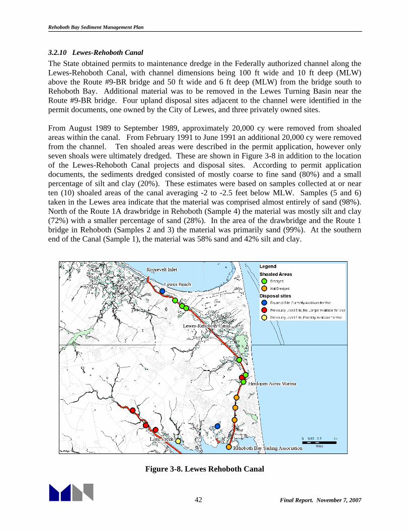
Rehoboth Bay Sediment Management Plan
42 Final Report. November 7, 2007
3.2.10 Lewes-Rehoboth Canal The State obtained permits to maintenance dredge in the Federally authorized channel along the Lewes-Rehoboth Canal, with channel dimensions being 100 ft wide and 10 ft deep (MLW) above the Route #9-BR bridge and 50 ft wide and 6 ft deep (MLW) from the bridge south to Rehoboth Bay. Additional material was to be removed in the Lewes Turning Basin near the Route #9-BR bridge. Four upland disposal sites adjacent to the channel were identified in the permit documents, one owned by the City of Lewes, and three privately owned sites. From August 1989 to September 1989, approximately 20,000 cy were removed from shoaled areas within the canal. From February 1991 to June 1991 an additional 20,000 cy were removed from the channel. Ten shoaled areas were described in the permit application, however only seven shoals were ultimately dredged. These are shown in Figure 3-8 in addition to the location of the Lewes-Rehoboth Canal projects and disposal sites. According to permit application documents, the sediments dredged consisted of mostly coarse to fine sand (80%) and a small percentage of silt and clay (20%). These estimates were based on samples collected at or near ten (10) shoaled areas of the canal averaging -2 to -2.5 feet below MLW. Samples (5 and 6) taken in the Lewes area indicate that the material was comprised almost entirely of sand (98%). North of the Route 1A drawbridge in Rehoboth (Sample 4) the material was mostly silt and clay (72%) with a smaller percentage of sand (28%). In the area of the drawbridge and the Route 1 bridge in Rehoboth (Samples 2 and 3) the material was primarily sand (99%). At the southern end of the Canal (Sample 1), the material was 58% sand and 42% silt and clay.
Figure 3-8. Lewes Rehoboth Canal

Rehoboth Bay Sediment Management Plan
43 Final Report. November 7, 2007
3.2.11 Burton’s Island Marina/Indian River Marina In 1970, the State of Delaware purchased Burton’s Island Marina (now known as Indian River Marina). Small dredging projects were performed in the marina during the 1970s, with 6,000 cy removed in March 1975, 8,500 cy removed in July 1976, and 9,000 cy removed in March 1978. Major renovations with a lifespan of 15 years were made in 1980 to 1981, including removal of 112,940 cy from March 1980 to November 1980. Additional maintenance dredging was performed from March to May 1982, with 6,000 cy removed. Docks and slips were added in 1988. In 1996, DNREC commissioned an engineering study and reconstruction plan. There followed several years of unsuccessful attempts to obtain state funding, ultimately prompting the Division of Parks and Recreation to develop a financing plan that utilized a portion of the 21st Century Parks Endowment Fund. Throughout 2002 and 2003 a series of meetings kept the public informed and allowed them to comment on the final design plans. From the reconstruction recommendations and the public meetings, several issues rose to the surface; specifically replacement of deteriorated floating docks, improved electrical services and dredging of the marina basin. The Division has responded to these concerns and has now completed all improvements related to these issues as well as many other improvements at the site. Phase I of the improvements included removal of 32,500 cy and Phase II removal of another 32,500 cy from the marina to dredge the basin to 7 ft deep (MLLW). Figure 3-6 shows the locations of the Burton’s Island Marina and Indian River Marina projects and disposal sites. 3.2.12 Wilson Creek No plans are available for the dredging of Wilson Creek which took place from June to August, 1983 with 27,000 cy removed. However, limited data indicate that the State senate passed an appropriation for dredging of Wilson Creek in FY 1980. The project was noted to benefit a private community, Nanticoke Shores Trailer Park, along Wilson Creek. Therefore it is assumed that the dredged channel extended at a minimum from this community through Wilson Creek to Rehoboth Bay. Figure 3-4 shows the location of the Wilson Creek dredging projects and disposal sites. 3.2.13 Rehoboth Bay Borrow Pits This project entailed a one-time filling of trenches previously dredged within Rehoboth Bay to obtain material for shoreline restoration following the 1962 storm. Material (166,035 cy) was obtained from a borrow area west of the trenches. Work was completed from September 1975 to July 1976. 3.2.14 Bald Eagle Creek A permit was initially applied for in the early 1980s to dredge Bald Eagle Creek from its outlet in Rehoboth Bay to a point 2,755 ft upstream, with dimensions 80 ft wide and 4 ft deep. However, the project was never completed. This area is of interest, however, because of the fact that in the early 1960s, portions of the creek were privately dredged to obtain fill for upland development. Anoxic holes with depths in excess of 15 ft remain (adjacent areas are shallow, 3-4 ft below MLW). These holes have been considered for disposal of material from the nearby Lewes-Rehoboth Canal. A budget request was submitted in 2005 for ecosystem restoration of the creek

Rehoboth Bay Sediment Management Plan
44 Final Report. November 7, 2007
using material dredged from the canal but the project has not moved forward. Figure 3-9 shows the location of the Bald Eagle Creek dredging project and potential restoration site.
Figure 3-9. Bald Eagle Creek
3.2.15 Feeder Beach at Indian River Inlet The “Feeder Beach” project was historically performed by DNREC prior to establishment of the sand bypassing plant at Indian River Inlet. It involved pumping sand from shoaled areas within the Inlet and the area known as Bottom Hills Drain onto the beach at the north side of Indian River Inlet. The project was designed to renourish the shoreline as well as protect and stabilize the approach to the inlet bridge. The project was dredged three times with 223,900 cy pumped from May 1982 to January 1983, 180,000 cy from November 1989 to March 1990, and 150,000 cy from January 1992 to April 1992. The sand bypass plant at the inlet was fully operational by 1992, alleviating the necessity of dredging this project. 3.2.16 Cozy Cove The Cozy Cove project was undertaken to improve navigable access to two private lagoon communities located in southwestern Rehoboth Bay, Cozy Cove and Lee Joseph Creek, with 17,745 cy removed from December 1978 to January 1979. While this project was completed with State funds at the time, it is unlikely that a project serving specific private communities would be undertaken again with State funding. Figure 3-4 shows the location for the Cozy Cove dredging project. No plans for this project were available, and similarly to Wilson Creek, the extents of the project were assumed to extend through the private lagoon communities.

Rehoboth Bay Sediment Management Plan
45 Final Report. November 7, 2007
A summary of the State dredging projects in the Inland Bays since Dredge Program was initiated in 1970 is presented in Table 3-2. Shaded cells and numbers illustrate dredging events/volumes (x 1,000 cy). Numbers in bold type represent initial dredging projects (e.g., Love Creek in 1970), whereas regular type represents maintenance volume dredging (e.g., Lewes-Rehoboth Canal in 1989-1991). As shown in the table, a total of 1,025,000 cy have been dredged as part of State waterway projects over roughly 37 years, over 70% of this volume was dredged as part of initial capital dredging projects. Only 343,000 cy were dredged as part of channel maintenance, and all of this maintenance dredging was in Federally authorized channels (i.e., Lewes-Rehoboth Canal, Massey’s’ Ditch, Indian River Bay, and Assawoman Canal). This volume equates to 9,300 cy/yr over 37 years, a relatively small amount, although most of the work was done in the late 80’s and early 90’s.
Table 3-2. Summary State Dredging Projects in the Inland Bays (x 1,000 cy) WATERWAY TOTAL Initial Maint. 70 71 72 73 74 75 76 77 78 79 80 81 82 83 84 85 86 87 88 89 90 91 92 93 94 95 96 97 98 99 0 1 2 3 4 5 6Lewes-Rehoboth Canal 40 40 20 20Love Creek 115 115 115Herring Creek 85 85 20 60 5Guinea Creek 75 75 75Wilson Creek 27 27 27Cozy Cove 18 18 18Massey’s Ditch 62 62 10 15 7 30
Indian River Bay 147 147 37 40 30 20 20
Pepper Creek 220 220 70 80 20 20 30Vines Creek 7 7 7White Creek 195 135 60 135 30 5 10 15Assawoman Canal 34 34 34
Grand Total Navigation 1,025 682 343Average Annual Maintenance 9.3 3.2.17 Contract Projects A number of contract projects have also been undertaken by the State, generally while the dredge was working on a project in the vicinity of the private site. These contract projects have primarily been small marinas and local access channels for private communities. In many cases, disposal took place at the disposal site for the primary project the dredge was working on at the time. Table 3-3 shows the contract projects undertaken and/or complete by the program in alphabetical order by project.

Rehoboth Bay Sediment Management Plan
46 Final Report. November 7, 2007
Table 3-3. Contract Dredging Projects in Rehoboth and Indian River Bays
Start Date End Date Location Volume
Removed (CY)
Purpose Dredge
December 1997 December 1997 Banks Harbor Marina (White Creek) 900 Marina Facility Blue Hen/Indian
River
June 1997 August 1997
Cedar Landing Subdivision Lagoon &
Access Channel (White Creek)
10,000 Navigational Channel
Blue Hen/Indian River
December 1997 March 1998
Cedar Landing Subdivision Lagoon &
Access Channel (White Creek)
10,000 Navigational Channel
Blue Hen/Indian River
April 1993 April 1993 Gull’s Way
Campground Marina (Vines Creek)
7,200 Marina Facility Blue Hen/Indian River
November 1977 February 1978 Henlopen Acres
Marina (adjacent to LNR Canal)
7,500 Marina Facility Dixie
I/Diamond State/Broadkill
January 1991 February 1991 Henlopen Acres Marina/Sandy
Bottoms 8,500 Marina Facility Blue Hen/Indian
River
September 1992 October 1992 Hunter’s Pointe Condominiums
(Millsboro) 1,250 Navigational
Channel Blue Hen/Indian
River
August 1994 August 1994 Hunter’s Pointe Condominiums 500 Navigational
Channel Blue Hen/Indian
River
January 1995 March 1995 Quillen’s Point (Cedar Neck) 12,000 Navigational
Channel
Dixie I/Diamond
State/Broadkill
December 1996 March 1997 Quillen’s Point (Cedar Neck) 15,000 Navigational
Channel Blue Hen/Indian
River
December 1998 January 1999 Rogers Haven Access
Channel & Lagoon (White Creek)
10,000 Navigational Channel
Blue Hen/Indian River
April 1975 May 1975
Rehoboth Bay Sailing Association (on
Rehoboth Bay South of Dewey Beach)
2,100 Marina Facility Dixie
I/Diamond State/Broadkill
June 1992 July 1992 Rehoboth Bay Sailing Association 1,800 Marina Facility Blue Hen/Indian
River

Rehoboth Bay Sediment Management Plan
47 Final Report. November 7, 2007
4. HYDRODYNAMIC MODELING The purpose of the hydrodynamic modeling effort was to assist in the development of a sediment management plan for the Delaware Inland Bays, specifically focused on Rehoboth Bay. The goal of the sediment management plan is to plan adequately for future dredging needs as well as to reduce the dependency on dredging. The modeling effort is meant to assess the conditions of Rehoboth and Indian River Bay, and to understand the hydrodynamics of the connection between Indian River and Rehoboth Bay in order to obtain information regarding areas requiring sediment management. One model was developed encompassing Indian River Bay and Rehoboth Bay and a significant region offshore. A number of previous hydrodynamic, water quality, and sediment studies have been conducted focusing on the Inland Bays. DNREC funded a water quality and hydrodynamic model study in 2002-2003 focusing on Total Maximum Daily Load (TMDL) computations (Kolluru and Fichera, 2003). The US Army Corps of Engineers (USACE) conducted an extensive hydrodynamic and eutrophication model study in the early 1990s, also providing valuable data (Raney et al., 1990 and Cerco et al., 1994). Several studies conducted at the University of Delaware also provide insight into erosion, sediment characteristics, and tides and currents in the bay (Chrzastowski, 1986 and Swisher, 1982). The present model was developed using bathymetry data obtained from the National Ocean Survey (NOS), DNREC, and USACE. The model grid includes higher resolution in areas of interest or where a detailed description of the bathymetry is required to accurately simulate the hydrodynamics (e.g., Massey’s Ditch). Grid resolution can also be increased in other areas of interest, should DNREC decide to examine those areas in more detail in the future. The model was forced with harmonic offshore tides with an additional meteorological component. Winds and discharge from Indian River were included in the model as well. This report presents model development, calibration and results for existing conditions over a representative tidal cycle. 4.1 Model Development 4.1.1 Overview of Delft3D Modeling System Modeling was performed using the Delft3D modeling system. Delft3D, which was developed by WL| Delft Hydraulics, is a state-of-the-art integrated surface water modeling system based on a flexible framework capable of simulating two- and three-dimensional interactions between flow, waves, water quality, ecology, sediment transport, and bottom morphology. The system gives direct access to state-of-the-art process knowledge, accumulated and developed at one of the world’s oldest and most renowned hydraulic institutes. Delft3D consists of a number of well-tested and validated modules, which are integrated with one-another. Delft3D FLOW module was specifically used to simulate the hydrodynamics within the Rehoboth and Indian River Bay model. This module is capable of simulating two-dimensional (2D, depth integrated) or three-dimensional (3D) unsteady flow and transport phenomena resulting from tidal and/or meteorological forcing, including the effect of density differences due

Rehoboth Bay Sediment Management Plan
48 Final Report. November 7, 2007
to a non-uniform temperature and salinity distribution (density-driven flow). This model can be used to predict the flow in shallow seas, coastal areas, estuaries, lagoons, rivers and lakes. It aims to model flow phenomena where the horizontal length and time scales are significantly larger than the vertical scales. When the fluid is regarded as vertically homogenous with respect to temperature, salinity, and thus density, a depth-averaged approach is appropriate. Delf3D-FLOW is able to run in two-dimensional mode (one-computational layer), which corresponds to solving the depth-averaged equations. Delft3D-FLOW’s system of equations consists of the horizontal equations of motion, the continuity equation and the transport equations for conservative constituents. The equations are formulated in orthogonal curvilinear coordinates. In curvilinear coordinates, the free surface level and bathymetry are related to a flat horizontal plane of reference. Flow forcing may include tidal variation at the open boundaries, wind stress at the free surface, and pressure gradients due to free surface gradients (barotropic) or density gradients (baroclinic). Source and sink terms are included in order to model the discharge and withdrawal of water. Delft3D-FLOW solves the Navier-Stokes equations for an incompressible fluid, under the shallow water and Boussinesq approximates. In the vertical momentum equation, the vertical accelerations are assumed to be negligible and are neglected; this leads to the hydrostatic pressure equation. 4.1.2 Model Grid Four sub-grids are combined to form the total grid structure of the model while allowing for varying resolution depending on shoreline geometry, bathymetry and level of interest in each specific area (Figure 4-1). The offshore sub-grid extends approximately 2.2 miles from the ocean shoreline. The maximum grid size (0.8 by 0.15 miles) occurs at the offshore boundary. The curvilinear grid passing through Massey’s Ditch has the finest resolution (23 ft by 39 ft). The grids are linked in Delft3D using the Domain Decomposition (DD) tool, which allows one domain to be divided into many different sub-domains with different degrees of resolution. This approach reduces computational demands by only refining local areas as opposed to the entire domain.

Rehoboth Bay Sediment Management Plan
49 Final Report. November 7, 2007
Figure 4-1: Model Grid
4.1.3 Bathymetry The bathymetry for the model, shown in Figure 4-2, was constructed using data available from GEODAS, DNREC, and the USACE Multi and Single Beam survey. The bathymetry throughout the Inland Bays was primarily interpolated from the DNREC survey taken in 2004. The areas immediately surrounding the inlet were interpolated using data from the Multi and Single Beam Surveys taken by USACE in 2004. The offshore areas were built from surveys collected by the NOS (GEODAS) that date back at least 20 years. Bathymetry sources are described in detail in Section 2.2.4.

Rehoboth Bay Sediment Management Plan
50 Final Report. November 7, 2007
Figure 4-2: Model Bathymetry
Indian River Inlet, the primary link between the ocean and the Inland Bays reaches depths of up to 100 ft below NGVD29. The rest of both Rehoboth and Indian River Bays is fairly shallow with depths in Indian River and Rehoboth Bay of less than 8 ft. Figure 4-3 shows the bathymetry in the region of the channels that link Indian River Bay to Rehoboth Bay.

Rehoboth Bay Sediment Management Plan
51 Final Report. November 7, 2007
Figure 4-3. Model bathymetry in the vicinity of Massey’s Ditch
4.1.4 Boundary Conditions The model was constructed with open-ocean forcing at its offshore boundary. Detailed water level measurements along this boundary are not available. Instead, tidal constituents can be used to construct a time series of water elevations. Tidal constituents were extracted for each end of the offshore boundary to capture any differences in the tide signal. Tidal constituents were obtained from the Advanced Circulation Model (ADCIRC) EastCoast2001 model. ADCIRC EastCoast2001 is a high-resolution, finite element tidal model of the Western North Atlantic Tidal (WNAT) domain developed by the US Army Corps of Engineers (Mukai et al. 2002). It encompasses the Western North Atlantic, the Caribbean Sea, and the Gulf of Mexico. ADCIRC EastCoast2001 provides the amplitudes and phases of the six main solar and lunar constituents (O1, K1, Q1, M2, S2, N2, and K2) as well as the M4 and M6 overtides. The computed amplitude of the seven major constituents (aside from M4 and M6) is within 6 to 13% of the measured amplitude and the computed phase is within 7 to 13 degrees of the measured phase. Data measurements contribute another 11% error to the amplitude and 7 degrees of error to the phase. This is the majority of error associated with the EastCoast2001 model (Mukai et al., 2001). Accuracy of the overtides has not been verified, and some error is inherent (ADCIRC Tidal Databases, 2006).

Rehoboth Bay Sediment Management Plan
52 Final Report. November 7, 2007
Table 4-1: Speed and Period of Major Tidal Constituents
Harmonic Constituent
Speed (deg/hr)
Period (hr) Description
O1 13.943 25.819 Principal lunar diurnal constituent
K1 15.041 23.935 Solar-lunar constituent
Q1 13.398 26.870 Larger lunar elliptic diurnal constituent
M2 28.984 12.421 Principal lunar tide
S2 30 12.000 Principal solar tide
N2 29.439 12.659
Monthly variation in lunar distance
K2 30.082 11.967 Changes in declination of sun and moon
M4 57.968 6.2103 Shallow water overtide of principal lunar constituent
M6 86.952 4.140 Shallow water overtide of principal lunar constituent
Wong (1988, 1994) showed that subtidal variability within the Inland Bays was mainly caused by meteorological forcing and subtidal water level changes offshore. Therefore, it is important to include these effects in the model in order to compare to real water level measurements. This offshore meteorological component (“residual”) was determined by subtracting the harmonic water level from the measured water level at Indian River Inlet. In order to resolve the subtidal variability, the difference between the raw water level and the predicted tide was processed using a 36 hour low-pass filter. To ensure that the signal at the Inlet was consistent with offshore conditions, the three closest NOAA stations: Cape May, NJ, Ocean City, MD, and Lewes, DE were compared with the extracted signal from Indian River Inlet. First, these three stations were compared for a four month period from August 2002 through November 2002 in order to determine the correlation between just these offshore stations. This period was chosen as the Ocean City Maryland gage was not deployed until August 2002. The results from this period

Rehoboth Bay Sediment Management Plan
53 Final Report. November 7, 2007
were compared using a linear least-squares regression analysis. The comparison of the year-long data is shown in Figure 4-4 The correlation of the meteorological components among the three gages is extremely high with coefficients greater than 0.95. The bias between Cape May and Lewes is 0.03 ft, while the bias between these two and Ocean City Inlet is slightly higher at 0.18 ft.
08/01/02 08/31/02 09/30/02 10/30/02 11/29/02
−1
0
1
2
3
Sub
tidal
ele
vatio
n (f
t, N
GV
D29
)
Lewes Ocean City Inlet Cape May Figure 4-4. Residual water levels extracted from NOAA data
In order to compare these results with the subtidal variability at Indian River Inlet, predicted and measured water levels were extracted at the Coast Guard Station, and an arbitrary time period in which all four gauges were in operation was chosen. This was to determine variability within the region, so as to justify the use of one or more of the signals. The comparison of the residual water level time series for October 2006 is shown in Figure 4-5. It is seen that the differences between stations is very small.
09/29/06 10/06/06 10/13/06 10/20/06 10/27/06
0
1
2
3
4
Sub
tidal
ele
vatio
n (f
t, N
GV
D29
)
Cape May Ocean City Inlet Lewes Indian River Inlet Figure 4-5. Residual water levels extracted from NOAA and Indian River Inlet
The resulting subtidal signal, which is attributed to meteorological effects, was compared between these four stations using a linear least-squares regression analysis. It was found that Lewes had the closest regression correlation to Indian River Inlet with a value of 1.02. It was also found that all four were similar in their structure, and the regression coefficient was within 0.2 of a perfectly correlated 1. It is assumed that the meteorological effects at Indian River Inlet were similar to those at the model offshore boundaries, and the residual extracted at the Inlet for the Model Calibration and Verification time periods was used at the offshore boundaries. Note that neither of the above comparison periods were used as inputs to the Model, but were selected

Rehoboth Bay Sediment Management Plan
54 Final Report. November 7, 2007
merely due to data continuity and availability. This analysis also shows that the use of any of the three offshore NOAA station data could be substituted for data obtained from Indian River Inlet in the case that data is unreliable or unavailable. 4.1.5 Calibration Model calibration was performed to both tidal harmonics as well as measured data. As explained above, model calibration was performed for the period of April 30, 2002 through July 2, 2002 in order to coincide with the data collection performed by Dr. Wong of the University of Delaware’s College of Marine Studies for DNREC’s TMDL study. In order to calibrate the Model, bed roughness and horizontal eddy viscosity were tuned until an acceptable calibration was obtained. Model performance was assessed by comparing time series of model results and by using three error estimates: correlation coefficient, root mean square (RMS) error and RMS error percentage. Correlation Coefficient: This uses the Pearson product moment correlation coefficient, r, that reflects the extent of a linear relationship between two data sets. This parameter indicates how closely the modeled data are in phase with the measured data. The parameter ranges from -1 to 1, with 1 indicating that both data sets are perfectly in phase, and -1 indicating a 180 degree phase shift. Root Mean Square (RMS) Error: The square root of the average square of the difference between each data point. The RMS error is described by the following:
nyx
RMS ii∑ −=
2)( where i=1…n
RMS Error Percentage: This computes the RMS error in the same manner as described above, however normalizes it over the range of the predicted or measured data. The RMS error is then described as a percentage of the total range, giving perspective on the magnitude of this value. For water levels, RMS errors of less than ten percent are desirable and a correlation coefficient greater than 0.90 indicates that the water levels are acceptably in phase. For currents, RMS errors of less than 20 percent are desirable and a correlation coefficient of greater than 0.80 indicates that the modeled currents are acceptable in phase. The statistical parameters for currents are less rigorous than for water levels, because small scale variations in bathymetry, geometry, and flow patterns can significantly affect current velocity and direction. Tidal Harmonic Calibration The tidal harmonic calibration was performed for water levels at three locations throughout the Delaware Inland Bays. These locations were USGS water level elevation stations. Their locations are shown Figure 4-6. In addition, harmonics were extracted from a USGS water elevation gauge placed in Massey’s Ditch between 1991 and 1993. The period for calibration includes a full spring-neap tidal cycle and coincides with data collection performed by Dr. K. Wong with the University of Delaware.
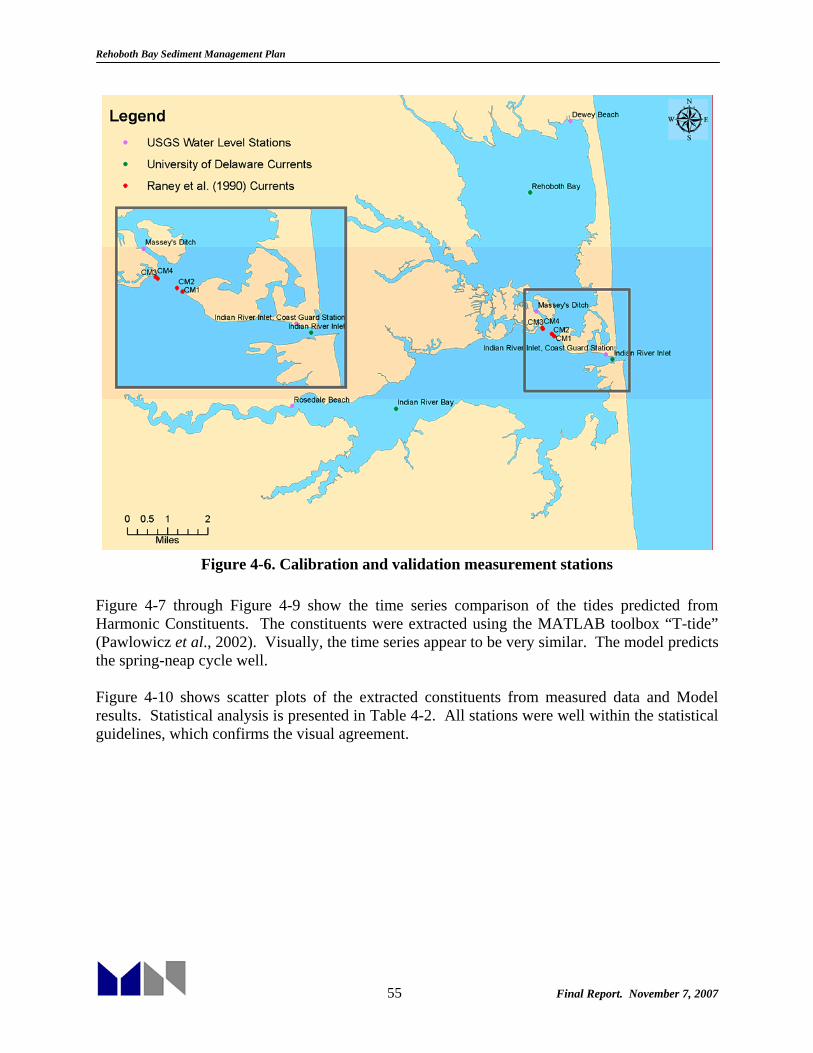
Rehoboth Bay Sediment Management Plan
55 Final Report. November 7, 2007
Figure 4-6. Calibration and validation measurement stations
Figure 4-7 through Figure 4-9 show the time series comparison of the tides predicted from Harmonic Constituents. The constituents were extracted using the MATLAB toolbox “T-tide” (Pawlowicz et al., 2002). Visually, the time series appear to be very similar. The model predicts the spring-neap cycle well. Figure 4-10 shows scatter plots of the extracted constituents from measured data and Model results. Statistical analysis is presented in Table 4-2. All stations were well within the statistical guidelines, which confirms the visual agreement.

Rehoboth Bay Sediment Management Plan
56 Final Report. November 7, 2007
05/01/02 05/08/02 05/15/02 05/22/02 05/29/02
−2
−1
0
1
2
Ele
vatio
n (f
t)
06/01/02 06/08/02 06/15/02 06/22/02 06/29/02
−2
−1
0
1
2
Ele
vatio
n (f
t)
Figure 4-7. IRI CG Station Tidal Harmonic Water Level Prediction vs Model Results
05/01/02 05/08/02 05/15/02 05/22/02 05/29/02
−2
−1
0
1
2
Ele
vatio
n (f
t)
06/01/02 06/08/02 06/15/02 06/22/02 06/29/02
−2
−1
0
1
2
Ele
vatio
n (f
t)
Figure 4-8. Rosedale Beach Tidal Harmonic Water Level Prediction vs Model Results
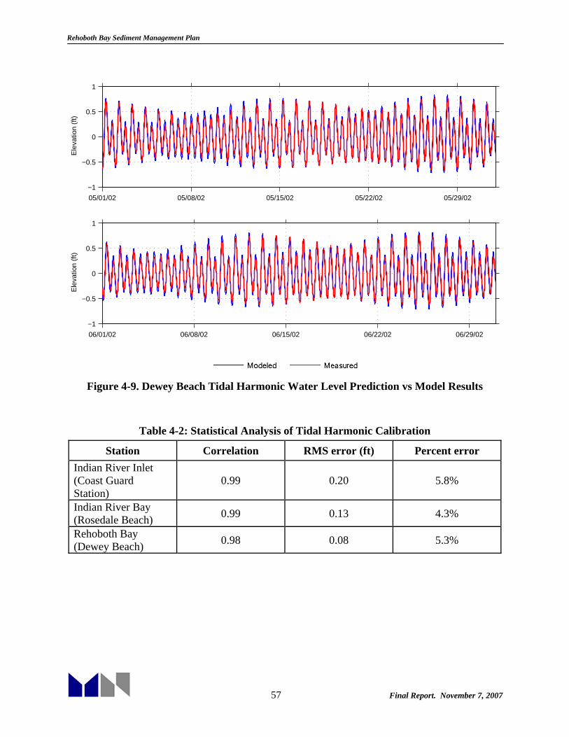
Rehoboth Bay Sediment Management Plan
57 Final Report. November 7, 2007
05/01/02 05/08/02 05/15/02 05/22/02 05/29/02
−1
−0.5
0
0.5
1
Ele
vatio
n (f
t)
06/01/02 06/08/02 06/15/02 06/22/02 06/29/02
−1
−0.5
0
0.5
1
Ele
vatio
n (f
t)
Figure 4-9. Dewey Beach Tidal Harmonic Water Level Prediction vs Model Results
Table 4-2: Statistical Analysis of Tidal Harmonic Calibration
Station Correlation RMS error (ft) Percent error Indian River Inlet (Coast Guard Station)
0.99 0.20 5.8%
Indian River Bay (Rosedale Beach) 0.99 0.13 4.3%
Rehoboth Bay (Dewey Beach) 0.98 0.08 5.3%
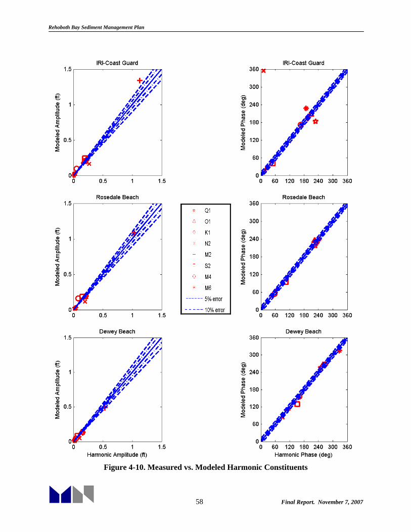
Rehoboth Bay Sediment Management Plan
58 Final Report. November 7, 2007
Figure 4-10. Measured vs. Modeled Harmonic Constituents

Rehoboth Bay Sediment Management Plan
59 Final Report. November 7, 2007
Calibration to Measured Data In order to compare model results with water level measurements, uniform time-varying winds were applied over the model and daily discharge from Indian River was applied as a source term. The calibration period was chosen to coincide with velocity measurements obtained from DNREC and collected by Dr. Wong from the University of Delaware. The model boundary conditions for this time period were applied to the offshore boundary and include meteorological effects obtained as described in the Boundary Conditions section. These effects were added to the predicted tides obtained from EastCoast2001 constituents giving the offshore time signal shown in Figure 4-11.
05/01/02 05/08/02 05/15/02 05/22/02 05/29/02
−2
0
2
4
6
Ele
vatio
n (f
t, N
GV
D29
)
06/01/02 06/08/02 06/15/02 06/22/02 06/29/02
−2
0
2
4
6
Ele
vatio
n (f
t, N
GV
D29
)
Figure 4-11. Offshore Boundary Conditions
The only boundary conditions employed were those at the offshore boundaries. Boundaries associated with the Lewes-Rehoboth Canal were not included as the exchange with the Delaware Bay through this canal is limited and not significant to the circulation patterns throughout Indian River and Rehoboth Bays (Wong, 1994). Previous hydrodynamic modeling efforts for the Inland Bays did not include this exchange either (Raney et al. 1990, Cerco et al. 1994). Raney et al. (1990) claims that the effect of the Lewes-Rehoboth Canal as well as the Assawoman Canal are “negligible compared with the tidal input at Indian River Inlet.” Little Assawoman Bay has no direct connection with the ocean, however links to Indian River Bay through White Creek to the Assawoman Canal and to Assawoman Bay. Assawoman Bay has contact with the ocean through Ocean City Inlet in Ocean City, Maryland. Tidal exchange through the Little Assawoman Canal was not used in previous hydrodynamic modeling efforts for Indian River and Rehoboth Bays. (Raney et al. 1990, Cerco et al. 1994).

Rehoboth Bay Sediment Management Plan
60 Final Report. November 7, 2007
River Discharge The effects of freshwater discharge into the Inland Bays were found by Cerco et al. (1994) to be negligible with the exception of the upstream end of Indian River Bay, where circulation and salinity patterns were affected by the inflow from Indian River. Nonetheless, discharge was included in the model. Specifically, mean daily discharge was obtained from USGS at the Millsboro Pond outlet station for the inflow from Indian River. Discharge values for the Model calibration time period are shown in Figure 4-12.
05/01/02 05/08/02 05/15/02 05/22/02 05/29/02
0
20
40
60
80
100
120
140
Dis
char
ge (
cfs)
06/01/02 06/08/02 06/15/02 06/22/02 06/29/02
0
20
40
60
80
100
120
140
Mea
n D
aily
Dis
char
ge (
cfs)
Figure 4-12. Indian River Discharge during Model Calibration Period
Winds Wind data were obtained from the National Climactic Data Center (NCDC) at three locations in relatively close proximity to Rehoboth and Indian River Bay. The closest data station is the Indian River Inlet Coast Guard Station (CGS), however the data from this station is limited and was not complete after the mid-1980’s. The closest station having complete records for the calibration time frame was Georgetown-Sussex Airport. This station was approximately 19 miles west of the study site. Wind speeds and directions were obtained in hourly increments over the two month calibration period and are shown in Figure 4-13.

Rehoboth Bay Sediment Management Plan
61 Final Report. November 7, 2007
05/01/02 05/08/02 05/15/02 05/22/02 05/29/02
−30
−20
−10
0
10
20
30 W
ind
Spe
ed (
ft/s)
06/01/02 06/08/02 06/15/02 06/22/02 06/29/02
−30
−20
−10
0
10
20
30
Win
d S
peed
(ft/
s)
Figure 4-13. Wind Speed and direction from Georgetown Airport for Calibration Period
Water Levels Measured water level data were available at the USGS stations shown in Figure 4-6. Figure 4-14 through Figure 4-16 present the results graphically. All results are presented to NGVD29 datum. By visually inspecting the figures, it can be seen that the Model does an adequate job of simulating measured water level data throughout Rehoboth and Indian River Bay. Water level results are still within statistical guidelines indicating good agreement as shown in Table 4-3. Note that for the comparison with real water levels, the percent RMS error was calculated using the maximum and minimum water levels during the calibration period.

Rehoboth Bay Sediment Management Plan
62 Final Report. November 7, 2007
05/01/02 05/08/02 05/15/02 05/22/02 05/29/02
−2
−1
0
1
2
3
4E
leva
tion
(ft,
NG
VD
29)
06/01/02 06/08/02 06/15/02 06/22/02 06/29/02
−2
−1
0
1
2
3
4
Ele
vatio
n (f
t, N
GV
D29
)
Figure 4-14. IRI CG Station Measured Water Levels vs Model Results
05/01/02 05/08/02 05/15/02 05/22/02 05/29/02
−2
−1
0
1
2
3
4
Ele
vatio
n (f
t, N
GV
D29
)
06/01/02 06/08/02 06/15/02 06/22/02 06/29/02
−2
−1
0
1
2
3
4
Ele
vatio
n (f
t, N
GV
D29
)
Figure 4-15. Rosedale Beach Measured Water Levels vs Model Results

Rehoboth Bay Sediment Management Plan
63 Final Report. November 7, 2007
05/01/02 05/08/02 05/15/02 05/22/02 05/29/02
−2
−1
0
1
2
3
4
Ele
vatio
n (f
t, N
GV
D29
)
06/01/02 06/08/02 06/15/02 06/22/02 06/29/02
−2
−1
0
1
2
3
4
Ele
vatio
n (f
t, N
GV
D29
)
Figure 4-16. Dewey Beach Measured Water Level vs Model Results
Table 4-3: Statistical Analysis of Measured Water Level Calibration Station Correlation RMS error (ft) Percent error
IRI (Coast Guard Station)
0.98 0.22 4.5%
Indian River Bay (Rosedale Beach)
0.98 0.25 5.2%
Rehoboth Bay (Dewey Beach)
0.95 0.27 8.4%
Currents Currents were calibrated against measured values at three stations shown in Figure 4-6. A bottom mounted current meter was placed at each station. These instruments collected data in 15 minute increments. The instruments collected currents in E/W and N/S components. They were also programmed to collect salinity and temperature data simultaneously. The deployment of this instrumentation was conducted by Dr. K. Wong of the University of Delaware in order to collect data for the DNREC-funded TMDL study in 2002 (Kolluru and Fichera, 2003). His unpublished current data were obtained from DNREC. Note that exact locations of these stations

Rehoboth Bay Sediment Management Plan
64 Final Report. November 7, 2007
were not reported by the investigator, and therefore locations in the general vicinity of the measurement locations were selected from the Model.
Figure 4-17, Figure 4-18, and Figure 4-19 show graphical comparison of Model results and measured currents. Only the primary direction of flow is shown in comparison. In Rehoboth Bay, both N/S and E/W flow were on the same order of magnitude, and are both shown. Statistical analysis of each component is shown in Table 4-4. Visual inspection shows that the modeled currents closely match the University of Delaware measurements. Some of the time series displayed are shorter in time than the others. This is due to signal noise coming from the measured data. It is assumed that the instruments stopped collection at different times.
Table 4-4: Statistical Analysis of Measured Current Calibration Station Correlation RMS error (ft/sec) Percent error Indian River Inlet 0.97 0.66 6.3% Indian River Bay (E/W component)
0.95 0.15 9.5%
Indian River Bay (N/S-component)
0.88 0.17 21.7%
Rehoboth Bay (E/W-component)
0.36 0.09 11.5%
Rehoboth Bay (N/S-component)
0.83 0.11 13.6%
The Model performed well in estimating the primary tidal components (through the inlet, the east-west component of Indian River Bay, and the north-south component in Rehoboth Bay). The primary components of the velocity through the inlet are an order of magnitude greater than the north-south component since most of the flow is being forced through the inlet in one direction. The primary component in Indian River Bay (east-west) is more than double the magnitude of the north-south component. The east-west component in Rehoboth Bay is as important as the north-south component in magnitude, however the model does not reproduce its variation as well. This is likely due to the fact that the winds used in forcing the Model were obtained from the Georgetown Airport which is 19 miles from Indian River Inlet. The winds measured at Georgetown Airport are land based winds which tend to be much smaller in magnitude than those coming off of the ocean in the westerly direction through Rehoboth Bay. When looking at the E/W plot of velocities in Rehoboth Bay, the bias between model and measured data is most pronounced in the negative, or westerly, direction. In order to improve the results obtained for this component, more accurate local wind measurements would be necessary.

Rehoboth Bay Sediment Management Plan
65 Final Report. November 7, 2007
05/01/02 05/08/02 05/15/02 05/22/02 05/29/02
−6
−4
−2
0
2
4
6
Vel
ocity
(ft/
s)
06/01/02 06/08/02 06/15/02 06/22/02 06/29/02
−6
−4
−2
0
2
4
6
Vel
ocity
(ft/
s)
Figure 4-17. Indian River Inlet Measured vs. Modeled Currents
05/01/02 05/08/02 05/15/02 05/22/02 05/29/02
−1
−0.5
0
0.5
1
Vel
ocity
(ft/
s)
06/01/02 06/08/02 06/15/02 06/22/02 06/29/02
−1
−0.5
0
0.5
1
Vel
ocity
(ft/
s)
Figure 4-18. Indian River Bay Measured vs. Modeled Currents (E/W-component)

Rehoboth Bay Sediment Management Plan
66 Final Report. November 7, 2007
Rehoboth Bay N/S-component
05/01/02 05/08/02 05/15/02 05/22/02 05/29/02
−0.4
−0.2
0
0.2
0.4
Vel
ocity
(ft/
s)
06/01/02 06/08/02 06/15/02 06/22/02 06/29/02
−0.4
−0.2
0
0.2
0.4
Vel
ocity
(ft/
s)
Rehoboth Bay – E/W Component
05/01/02 05/08/02 05/15/02 05/22/02 05/29/02
−0.4
−0.2
0
0.2
0.4
Vel
ocity
(ft/
s)
06/01/02 06/08/02 06/15/02 06/22/02 06/29/02
−0.4
−0.2
0
0.2
0.4
Vel
ocity
(ft/
s)
Figure 4-19. Rehoboth Bay Measured vs. Modeled Currents

Rehoboth Bay Sediment Management Plan
67 Final Report. November 7, 2007
4.1.6 Model Verification It is necessary to verify that the model is applicable to time periods and forcing conditions other than those used in the calibration period. The time period selected to verify the model was from 30 June 1988 through 15 July 1988 which encompasses the time periods used for calibration in Cerco et al. (1994) and Raney et al. (1990). This was one of the only time periods available with current data. Wind, discharge and offshore boundary conditions are found in Figure 4-20 through Figure 4-22. Winds were unavailable from Georgetown-Sussex Airport and Indian River Inlet for the time period specified and were instead obtained from Dover Air Force Base.
06/30/88 07/07/88 07/14/88
−4
−2
0
2
4
Ele
vatio
n (f
t, N
GV
D29
)
Figure 4-20. Boundary Conditions for Verification Period
06/30/88 07/07/88 07/14/88
25
30
35
40
45
50
55
Mea
n D
aily
Dis
char
ge (
cfs)
Figure 4-21. Indian River Discharge for Verification Period
06/30/88 07/07/88 07/14/88
−30
−20
−10
0
10
20
30
Win
d S
peed
(ft/
s)
Figure 4-22. Wind Speed and Direction from Dover Air Force Base for Verification Period

Rehoboth Bay Sediment Management Plan
68 Final Report. November 7, 2007
Water Levels Water levels from the model verification period were obtained from the USGS. Only two of the water level gauges shown in Figure 4-6 were operational during the target period, the Coast Guard Station at Indian River Inlet, and Rehoboth Bay at Dewey Beach. The Rosedale Beach gauge was not operational. Figure 4-23 shows the graphical comparison for the Coast Guard station and Dewey Beach water level gauges. Note that the Coast Guard station data were available only beginning at 17:00 hours on June 29, 1988. Table 4-2 shows the statistical comparison for the water levels.
IRI Coast Guard
06/30/88 07/07/88 07/14/88
−2
−1
0
1
2
3
Ele
vatio
n (f
t, N
GV
D29
)
Dewey Beach
06/30/88 07/07/88 07/14/88
−0.5
0
0.5
1
1.5
2
Ele
vatio
n (f
t, N
GV
D29
)
Figure 4-23. Measured vs. Modeled Water Levels for Verification Period
Table 4-5: Statistical Analysis of water levels for Verification Period
Station Correlation RMS error (ft) Percent error Indian River Inlet (CG Station)
0.95 0.34 8.6%
Rehoboth Bay (Dewey Beach)
0.94 0.17 8.8%
Currents Raney et al. (1990) employed current data collected from June 29 through July 1, 1988 in calibration of the hydrodynamic model of the Indian River Bay – Rehoboth Bay system. Currents were collected at four stations on either side of Middle Island (Cerco et al. 1994, Raney

Rehoboth Bay Sediment Management Plan
69 Final Report. November 7, 2007
et al. 1990). These data were obtained by digitizing the data points published in Raney et al. (1990). With this process there is a certain amount of error introduced into the data. The positions of the four gauges are shown in Figure 4-6. The measurements were only taken for a total of approximately 22 hours from June 30, 1988 through July 1, 1988. Figure 4-24 show the graphical results of the current comparison. Due to the limited time frame and error introduced in extracting the data points, no statistical analysis was performed. Visually, the currents agree reasonably well, although there are some noticeable differences, particularly at stations CM2 and CM4. These differences probably owe to a combination of model calibration, digitizing errors, and, more importantly, inaccuracies in the bathymetry used in the model. Currents in this area are very sensitive to bottom morphology and the exact bathymetry at the time of the measurements was not available. Nonetheless, it is concluded that that velocities in the region linking Indian River and Rehoboth Bays are predicted well by the Model. 4.2 Existing Hydrodynamic Conditions The Model developed and calibrated in the previous section was used to assess hydrodynamic conditions within Indian River and Rehoboth Bays. Existing hydrodynamic conditions (water levels, discharge and currents) as predicted by the model are described in detail in the following paragraphs. 4.2.1 Water Elevations Model results from the two month calibration period were used to estimate tidal range in the Bays. Results were consistent with previous findings and experimental data from the same time period (Table 4-6). This table indicates that most of the ocean tidal range at the inlet propagates through to Indian River Bay (Rosedale Beach), and that the range is decreased by almost half within Rehoboth Bay (Dewey Beach). Long-term tidal range reported by NOAA the Inlet is 2.51 ft, which is very similar to those calculated from the two-month period and presented in Table 4-6.
Table 4-6: Average Tidal Range during Calibration Period Location Model
Indian River Inlet – CG Station 2.6 ft Rosedale Beach 2.4 ft Dewey Beach 1.3 ft
As shown in Figure 4-14 through Figure 4-16, there are periods when the water level throughout the system remains above mean sea level for several tidal cycles. These higher elevations are associated to the meteorological component of the offshore boundary (Figure 4-11) that propagates throughout the Inland Bays. Figure 4-25 and Figure 4-26 show the maximum and minimum water levels throughout the Model calibration time period for the entire system. It is seen that water levels are higher offshore (due to having larger meteorological component and larger tidal range) than within Indian River and Rehoboth Bay. It is also seen that the maximum and minimum water levels within Rehoboth Bay are significantly smaller in magnitude than those in Indian River Bay and the Inlet, with the magnitude reduction most pronounced in the minimum water levels or ebb tide.
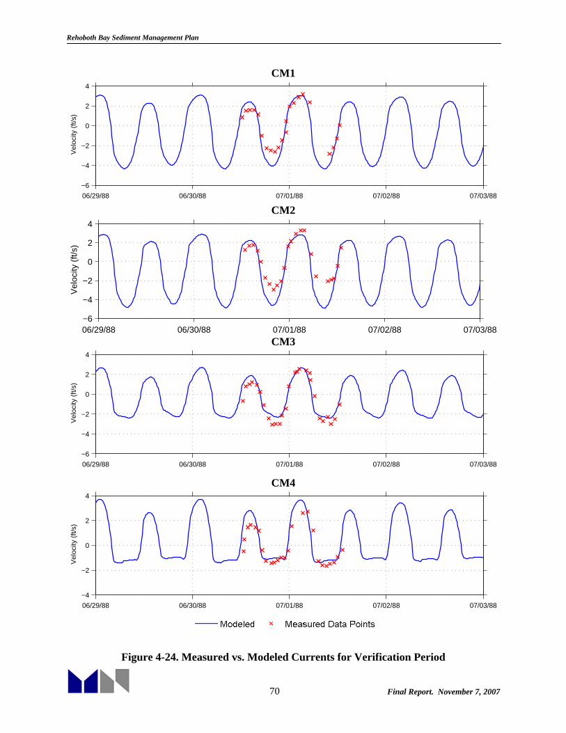
Rehoboth Bay Sediment Management Plan
70 Final Report. November 7, 2007
CM1
06/29/88 06/30/88 07/01/88 07/02/88 07/03/88
−6
−4
−2
0
2
4
Vel
ocity
(ft/
s)
CM2
06/29/88 06/30/88 07/01/88 07/02/88 07/03/88−6
−4
−2
0
2
4
Vel
ocity
(ft/
s)
CM3
06/29/88 06/30/88 07/01/88 07/02/88 07/03/88
−6
−4
−2
0
2
4
Vel
ocity
(ft/
s)
CM4
06/29/88 06/30/88 07/01/88 07/02/88 07/03/88
−4
−2
0
2
4
Vel
ocity
(ft/
s)
Figure 4-24. Measured vs. Modeled Currents for Verification Period

Rehoboth Bay Sediment Management Plan
71 Final Report. November 7, 2007
Figure 4-25. Maximum Water Level during calibration period
Figure 4-26. Minimum Water Level during calibration period
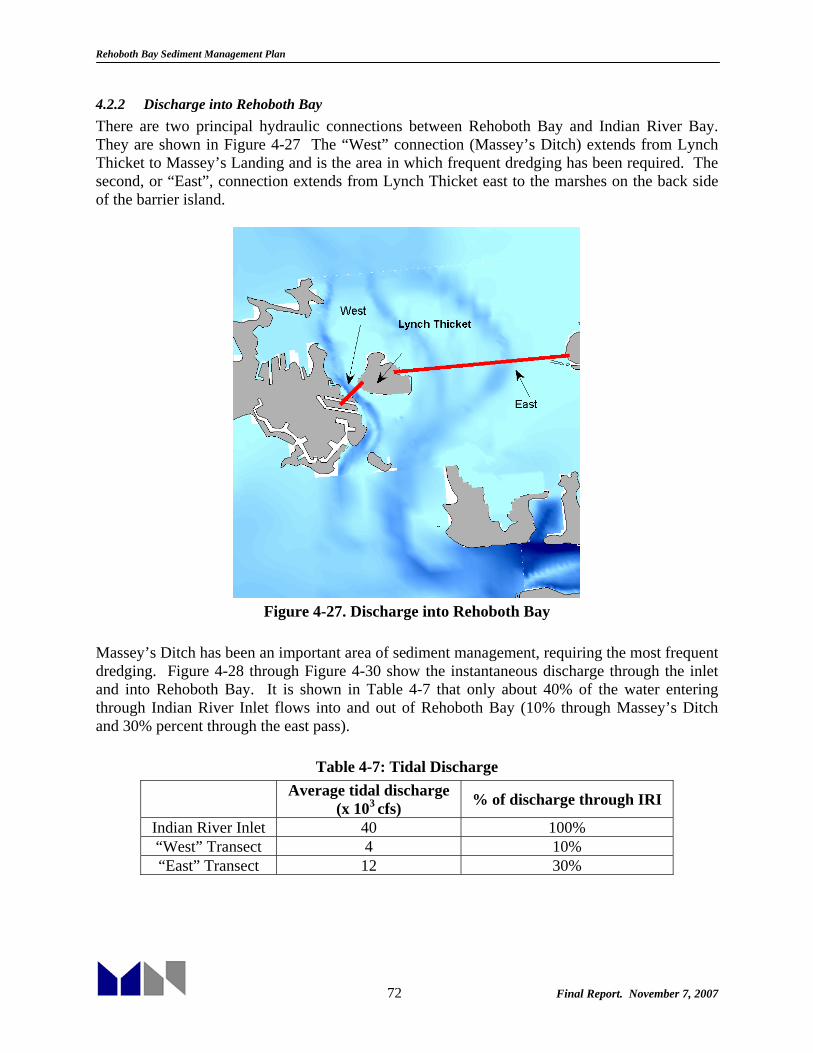
Rehoboth Bay Sediment Management Plan
72 Final Report. November 7, 2007
4.2.2 Discharge into Rehoboth Bay There are two principal hydraulic connections between Rehoboth Bay and Indian River Bay. They are shown in Figure 4-27 The “West” connection (Massey’s Ditch) extends from Lynch Thicket to Massey’s Landing and is the area in which frequent dredging has been required. The second, or “East”, connection extends from Lynch Thicket east to the marshes on the back side of the barrier island.
Figure 4-27. Discharge into Rehoboth Bay
Massey’s Ditch has been an important area of sediment management, requiring the most frequent dredging. Figure 4-28 through Figure 4-30 show the instantaneous discharge through the inlet and into Rehoboth Bay. It is shown in Table 4-7 that only about 40% of the water entering through Indian River Inlet flows into and out of Rehoboth Bay (10% through Massey’s Ditch and 30% percent through the east pass).
Table 4-7: Tidal Discharge
Average tidal discharge (x 103 cfs) % of discharge through IRI
Indian River Inlet 40 100% “West” Transect 4 10% “East” Transect 12 30%

Rehoboth Bay Sediment Management Plan
73 Final Report. November 7, 2007
05/01/02 05/08/02 05/15/02 05/22/02 05/29/02
−2
−1
0
1
2x 10
5F
low
(cf
s)
Figure 4-28. Discharge through Indian River Inlet
05/01/02 05/08/02 05/15/02 05/22/02 05/29/02
−2
−1
0
1
2x 10
4
Flo
w (
cfs)
Figure 4-29. Discharge through “West” Transect (Massey’s Ditch)
05/01/02 05/08/02 05/15/02 05/22/02 05/29/02
−4
−2
0
2
4
6x 10
4
Flo
w (
cfs)
Figure 4-30. Discharge through “East” Transect
Figure 4-31 through Figure 4-33 show cumulative discharge through Indian River Inlet and the “East” and “West” transects between Indian River Bay and Rehoboth Bay. The figures show a net ebb (south) discharge through Massey’s Ditch and net flood (north) discharge through the east pass, which suggest a counterclockwise residual circulation pattern in and out of Rehoboth Bay and around Lynch Thicket.

Rehoboth Bay Sediment Management Plan
74 Final Report. November 7, 2007
05/01/02 05/08/02 05/15/02 05/22/02 05/29/02−2
−1
0
1
2
x 109
Cum
ulat
ive
Dis
char
ge (
ft3 )
Figure 4-31. Cumulative discharge through Indian River Inlet
05/01/02 05/08/02 05/15/02 05/22/02 05/29/02
−15
−10
−5
0
5x 10
8
Cum
ulat
ive
Dis
char
ge (
ft3 )
Figure 4-32. Cumulative Discharge through West
05/01/02 05/08/02 05/15/02 05/22/02 05/29/02
0
0.5
1
1.5
2
2.5x 10
9
Cum
ulat
ive
Dis
char
ge (
ft3 )
Figure 4-33. Cumulative Discharge through East
4.2.3 Currents Historically, one of the locations requiring most frequent dredging is the area in and near Massey’s Ditch. The ebb and flood velocities through Massey’s Ditch are shown in Figure 4-34 and Figure 4-35. Bathymetry contours are shown every 5 ft. The areas surrounding the island are marshes, and are not inundated all of the time. These points are shallow enough that velocities through the marshy areas are much smaller than their neighbors through the ditch.
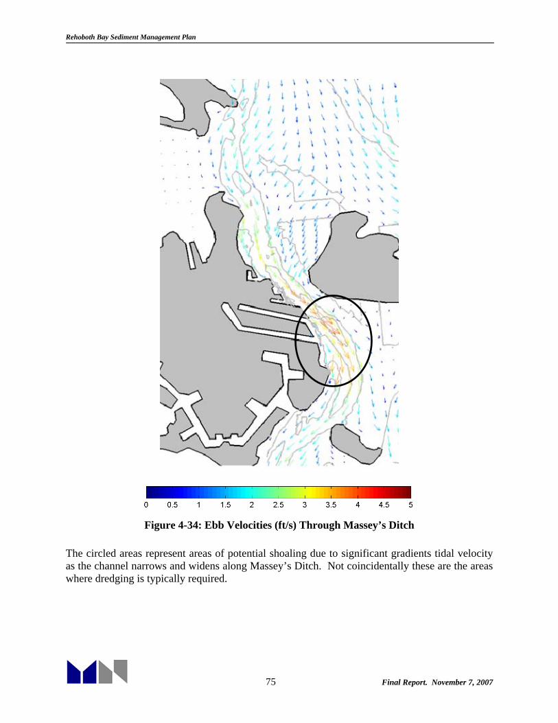
Rehoboth Bay Sediment Management Plan
75 Final Report. November 7, 2007
Figure 4-34: Ebb Velocities (ft/s) Through Massey’s Ditch
The circled areas represent areas of potential shoaling due to significant gradients tidal velocity as the channel narrows and widens along Massey’s Ditch. Not coincidentally these are the areas where dredging is typically required.

Rehoboth Bay Sediment Management Plan
76 Final Report. November 7, 2007
Figure 4-35: Flood Velocities (ft/s) Through Massey’s Ditch Figure 4-36 shows the maximum velocities throughout two bays. The maximum velocities are found in and around Indian River Inlet, reaching magnitudes of over 5 ft/s. The channels leading to Rehoboth Bay reach magnitudes over 4 ft/s. Indian River Bay on a whole has velocities higher than those in Rehoboth Bay, with velocities in Rehoboth Bay not reaching above 1 ft/s. The low velocities through Rehoboth Bay may indicate potential sedimentation problems throughout the bay, and especially in the tributaries.

Rehoboth Bay Sediment Management Plan
77 Final Report. November 7, 2007
Figure 4-36: Maximum Velocities throughout Indian River and Rehoboth Bays
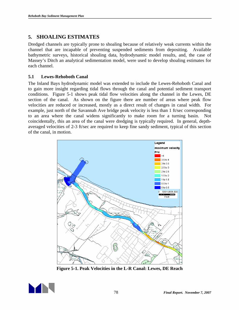
Rehoboth Bay Sediment Management Plan
78 Final Report. November 7, 2007
5. SHOALING ESTIMATES Dredged channels are typically prone to shoaling because of relatively weak currents within the channel that are incapable of preventing suspended sediments from depositing. Available bathymetric surveys, historical shoaling data, hydrodynamic model results, and, the case of Massey’s Ditch an analytical sedimentation model, were used to develop shoaling estimates for each channel. 5.1 Lewes-Rehoboth Canal The Inland Bays hydrodynamic model was extended to include the Lewes-Rehoboth Canal and to gain more insight regarding tidal flows through the canal and potential sediment transport conditions. Figure 5-1 shows peak tidal flow velocities along the channel in the Lewes, DE section of the canal. As shown on the figure there are number of areas where peak flow velocities are reduced or increased, mostly as a direct result of changes in canal width. For example, just north of the Savannah Ave bridge peak velocity is less than 1 ft/sec corresponding to an area where the canal widens significantly to make room for a turning basin. Not coincidentally, this an area of the canal were dredging is typically required. In general, depth-averaged velocities of 2-3 ft/sec are required to keep fine sandy sediment, typical of this section of the canal, in motion.
Figure 5-1. Peak Velocities in the L-R Canal: Lewes, DE Reach

Rehoboth Bay Sediment Management Plan
79 Final Report. November 7, 2007
Although south of the Savannah Ave bridge velocities increase, there are significant gradients in velocity as the canal narrows near the two existing bridges and the old railroad bridge abutments. This narrowing of the channel results in increased velocities locally, but as velocities are reduced farther away from the abutments sediment in suspension falls out and results in several chronically shallow areas that were last dredged by the State in 1989-1991 (see Section 3.2.10). Hydrodynamic model results and recent available Corp surveys (1999, 2001, 2003 and 2005), were used to develop shoaling estimates. Results from this analysis suggest that the dredging required in this reach of the L-R Canal (from the Theodore C Freeman Hwy Bridge north to Roosevelt Inlet) would be in the order of 5,000 to 10,000 cy/yr with most of the sediment accumulating in the turning basin and along the “bend” immediately north of it. Note that this estimate does not include shoaling in the inlet itself, which is assumed would continue to be dredged by the Corps. Dredging frequency would probably have to be on the order of every 2 to 4 years. Farther south along the Cape Henlopen State Park section of the canal (Figure 5-2), a relatively straight and uniform channel, combined with relatively high tidal velocities appear to effectively prevent shoaling, as a result this reach as not been dredged since at least the 1960’s, and it is assumed that minimal or no dredging will be required in the future.
Figure 5-2. Peak Velocities in the L-R Canal: Cape Henlopen State Park Reach

Rehoboth Bay Sediment Management Plan
80 Final Report. November 7, 2007
In the Henlopen Acres section of the canal (Figure 5-3) there a few areas prone to shoaling. The first one is near the mouth of Holland Glade, where increased sediment loads from the creek and flow conditions at the intersection between the canal are likely causes of increased sedimentation. As of 1999 controlling depths in this area (just north of the mouth of the creek) were less than 4 ft below MLW. Farther south controlling depths increase to more than -6 ft MLW and stay that way until reaching Henlopen Acres Marina, where a significant reduction in flow velocities (Figure 5-3) appears to the be the root cause of another chronically shoaling area of the canal. As of 1999, roughly 10 years after last being dredged, the controlling depth in this area was roughly -5 ft MLW. It is unclear how much shoaling occurred during that interval since post-dredging surveys are not available, but it does not appear to be an exceedingly fast shoaling rate given the relatively deep channel conditions 10 years after dredging. Overall, the shoaling rate (based on a channel maintained at -6 ft MLW) within the Henlopen Acres Reach of the L-R Canal is estimated at 1,000 to 2,000 cy/yr. Dredging frequency in this reach will probably be controlled by conditions near the mouth of Holland Glade. South of the Henlopen Acres Marina the canal straightens again and velocities are relatively high (over 3 ft/sec), so at least within the area shown on Figure 5-3, channel depths remain consistently at 5 to 6 ft MLW.
Figure 5-3. Peak Velocities in the L-R Canal: Henlopen Acres Reach
However, as the canal enters the Rehoboth Beach section (Figure 5-4) and despite relatively high velocities (over 3 ft/sec), controlling depths are reduced to less than -4 ft MLW in some sections.

Rehoboth Bay Sediment Management Plan
81 Final Report. November 7, 2007
Shoaling is a problem particularly in the section between Route 1A and Route 1, where depths are less than -3 ft MLW in some sections. Note that this reach of the canal was supposed to have been dredged during the 1989-1991 dredging project, but lack of a nearby upland disposal site prevented it. As to the reason why the channel requires dredging in this area despite the relatively high velocities and straight geometry, most likely it owes to very steep banks on both shorelines. Erosion has probably contributed to sediment accumulation and a relatively narrow channel. Strong flows, however, have prevented the accumulation of silty sediments, as confirmed by the sandy sediment samples collected as part of the 1989-1991 State dredging project. It is difficult to predict sedimentation rates in this reach of the canal because of recent dredging projects and unique shoaling mechanism, but 10,000 to 15,000 cy would have to be dredged in order to get to project depth. After that, shoaling rates would likely exceed 2,000 cy/yr in this section of the canal unless the banks are stabilized and the sediment source removed.
Figure 5-4. Peak Velocities in the L-R Canal: Rehoboth Beach Reach
Between Bay Harbor and the southern end of the canal at Thompson Island depths increase slightly (5 to 6 ft below MLW) despite lack of dredging since the 1960’s. This is probably because the banks of the canal are not as steep in this area and velocities remain high, above 2.5 ft sec, as shown in Figure 5-5. However, a shallow area between the two jetties at the southern end of the canal is evident in recent USACE surveys (3-4 ft below MLW in 1999 and 1997). This situation is most likely due to the relatively poor condition of the jetties, which were

Rehoboth Bay Sediment Management Plan
82 Final Report. November 7, 2007
constructed almost 100 years ago and apparently have not been rehabilitated since. Deterioration is particularly evident along the western jetty near the existing shoreline, where a section roughly 100 ft long is missing or submerged. Sections roughly 200 and 100 ft long at the tips of the west and east jetties, respectively, are also submerged. This condition results in reduced flows through the inlet, increased lateral sediment loads and shoaling. Farther south, beyond the existing jetties, more shoaling occurs (less than -3 ft MLW in the vicinity of Buoys #1 and #2 in the 1999 survey), a condition typical of most stabilized coastal inlets resulting from tidal flow reduction beyond the jetties. This tendency is augmented by the naturally shallow waters of northern Rehoboth Bay and the poor condition of the jetties. Approximately 800 feet south of the jetties, depths increase again to slightly more than 6 ft below MLW along the narrow channel that crosses Rehoboth Bay from north to south. This area of the canal was also supposed to be dredged in 1989-1991 but was not because of lack of a nearby disposal site. Roughly 7,000 cy of sediment would have to be dredged along approximately 2,000 feet to create a channel at -6 ft MLW. Unfortunately, however, jetty conditions and hydrodynamics suggest that sedimentation would occur fairly rapidly again, particularly south of the jetties, and maintenance requirements could range from 2,000 to 4,000 cy/yr.
Figure 5-5. Peak Velocities in the L-R Canal: Thompson Island Reach

Rehoboth Bay Sediment Management Plan
83 Final Report. November 7, 2007
5.2 Love Creek As shown in Figure 4-36 above, maximum tidal flow velocities in Love Creek are less than 1 ft/sec. These slow velocities, combined with upstream sediment loadings and, more importantly, redistribution of existing sediments within Rehoboth Bay, result in an environment conducive to shoaling along the creek. As of 2004, according to a survey provided by DNREC, the Love Creek channel was 2-3 ft below MLW between the Route 24 bridge and Mulberry Knoll (i.e., the narrow section of the creek between the bridge and Markers 7&8). However between Mulberry Knoll (Markers 7&8) and the area opposite Robinson Landing (just upstream from Markers 3&4), the channel is less than -2 ft MLW. Farther south and east, depths increase gradually to slightly less than -4 ft MLW. Depths at the downstream end of the channel (Markers 1&2) are roughly -3.5 ft MLW.
Figure 5-6. Love Creek: 2004 Bathymetry and Channel Markers
Based on input from DNREC regarding users of this channel and the actual draft requirements a target depth of -4 ft MLW was assumed. Unfortunately even this relatively shallow depth would require significant dredging along the original channel length (2.2 miles). Moreover, it would require extending the original alignment approximately 4,000 ft downstream into Rehoboth Bay to reach naturally deep (-4 ft MLW) water. Initial dredging requirements based on present bathymetry would be in the order of 60,000 cy (including 0.5 ft overdredge), about a third of the original dredged volume and a very significant amount considering disposal site limitations. Maintenance volumes would be in the order of 3,000 to 5,000 cy/yr. The lower end of this range would require continued marking of the deeper channel thalweg by DNREC regardless of the design alignment to minimize dredging.

Rehoboth Bay Sediment Management Plan
84 Final Report. November 7, 2007
It would be possible to significantly reduce initial dredge volumes and future maintenance by dredging the channel to only 3 ft below MLW. This would reduce the length of channel to be dredged and future maintenance frequency and volume. However, this may not meet the local navigation needs. 5.3 Herring Creek & Guinea Creek Despite similar tide and sediment conditions, Herring Creek and Creek appear to be naturally deeper than Love Creek, at least along certain sections. Specifically, Herring Creek (Figure 5-7), from its confluence with Rehoboth Bay to just south of the mouth of Guinea Creek (from daymarker #1 to #8) appears to have a fairly deep channel (deeper than -4 ft MLW) albeit narrow in spots (e.g., the reach between Angola Landing and Island in the Narrows). Available surveys in 1998 and 2001 also indicate these depths are fairly stable as a result of relatively high current speeds in narrow sections of the Creek (e.g., Island in The Narrows) and channel marking by DNREC. Farther upstream, however, in the vicinity of Guinea Creek and Wolfpit Marsh (channel marker #9 to channel marker #18) Herring Creek widens and maximum depths are reduced to less than -4 ft MLW probably as a result of decreased currents associated with the widening of the creek. Nonetheless, channel marking has successfully maintained a channel between -3 and -4 ft MLW along this reach in recent years.
Figure 5-7. Herring Creek: 2001 Survey and Channel Markers
Finally, controlling channel depths increase to more than -4 ft MLW again north of Hoods Island as the creek narrows (Figure 5-8). Therefore, assuming that a -4 ft MLW channel also meets the
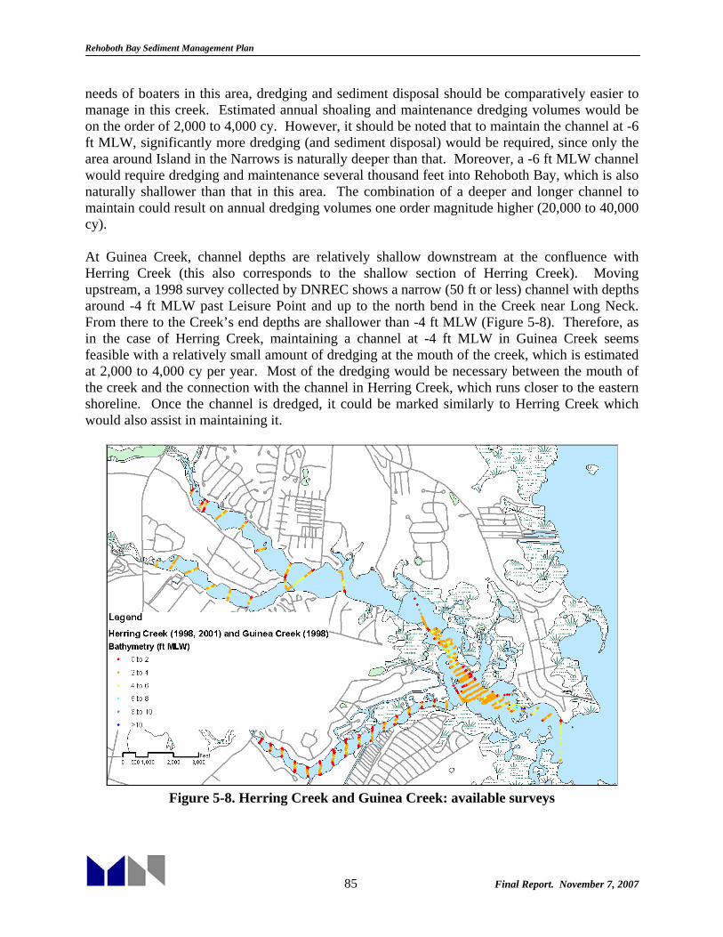
Rehoboth Bay Sediment Management Plan
85 Final Report. November 7, 2007
needs of boaters in this area, dredging and sediment disposal should be comparatively easier to manage in this creek. Estimated annual shoaling and maintenance dredging volumes would be on the order of 2,000 to 4,000 cy. However, it should be noted that to maintain the channel at -6 ft MLW, significantly more dredging (and sediment disposal) would be required, since only the area around Island in the Narrows is naturally deeper than that. Moreover, a -6 ft MLW channel would require dredging and maintenance several thousand feet into Rehoboth Bay, which is also naturally shallower than that in this area. The combination of a deeper and longer channel to maintain could result on annual dredging volumes one order magnitude higher (20,000 to 40,000 cy). At Guinea Creek, channel depths are relatively shallow downstream at the confluence with Herring Creek (this also corresponds to the shallow section of Herring Creek). Moving upstream, a 1998 survey collected by DNREC shows a narrow (50 ft or less) channel with depths around -4 ft MLW past Leisure Point and up to the north bend in the Creek near Long Neck. From there to the Creek’s end depths are shallower than -4 ft MLW (Figure 5-8). Therefore, as in the case of Herring Creek, maintaining a channel at -4 ft MLW in Guinea Creek seems feasible with a relatively small amount of dredging at the mouth of the creek, which is estimated at 2,000 to 4,000 cy per year. Most of the dredging would be necessary between the mouth of the creek and the connection with the channel in Herring Creek, which runs closer to the eastern shoreline. Once the channel is dredged, it could be marked similarly to Herring Creek which would also assist in maintaining it.
Figure 5-8. Herring Creek and Guinea Creek: available surveys

Rehoboth Bay Sediment Management Plan
86 Final Report. November 7, 2007
5.4 Massey’s Ditch Available survey data show that there are four areas in the vicinity of Massey’s Ditch that have caused repeated problems to navigation (Figure 5-9). Near the southern end of the Rehoboth Bay channel, just north of Bluff Point (location A), as the relatively fast flow through Massey’s Ditch enters Rehoboth Bay’s wider and shallower area, velocities are reduced significantly causing sediment within the water column to settle out of suspension. Further south, near Roman T Pond (location B) and also at the northern tip of the very narrow section of the Ditch (location C), the flow also widens leading to chronic shoaling. In addition, near the southern end of Massey’s Ditch a shoal is found that extends eastward from the western side (location D). This shoal extends almost the entire width of the ditch, ending just north of Middle Island. The last problematic area for navigation is south of Massey’s Ditch, near the connection with the flow from Big and Little Ditches (location E). A large shallow area extends from Middle Island to the south, and the channel crosses through this shoal.
Figure 5-9: Areas in need of frequent dredging near Massey’s Ditch
An analytical methodology originally developed by Eysink and Vermaas (1983) and further developed by M&N was used to estimate sedimentation within the Massey’s Ditch channel (see Appendix E). The method takes into account channel dimensions, natural water depth, settling velocity of the sediment, and estimated wave conditions. The hydrodynamic model that was developed in Task 2 was used to examine the flow conditions in the areas of interest. This model has areas of high resolution through Massey’s Ditch allowing
AA
BB
CC
DD
EE

Rehoboth Bay Sediment Management Plan
87 Final Report. November 7, 2007
for detailed view of the velocity patterns in the area. The areas of interest were examined in detail to determine the cause of sedimentation. The flow conditions predicted by the hydrodynamic model were used as inputs to the analytical shoaling model. The hydrodynamic model was modified to represent immediate post-dredge conditions. This is then assumed to give an accurate representation of the current patterns immediately following a dredging operation, when sedimentation would be at its peak. Bathymetry was kept similar to the survey conducted by DNREC (2004), however areas of interest were deepened to examine predicted flow conditions immediately post-dredge. Velocities were extracted from the model for use in an analytical approximation of shoaling in each of the examined areas (A through E). 5.4.1 Location A: Rehoboth Bay Channel North of Bluff Point Location A is near the north end of Massey’s Ditch. Flow in this area is traveling at high velocities through a deep channel, and when the channel expands and releases into Rehoboth Bay, the flow slows down significantly. This causes a deposition of sediment. The USACE surveys collected in July 2003 (Figure 5-10) show that the depth of the channel approximately one year after dredging still appears to be at almost 6 ft of depth. This part of the channel was dredged to approximately 6 ft below MLW in 2002.
1.4
0.7
1.6
2.6
3.8
4.3
5.2
5.8
6.1
5.8
5.7
6.3
7.8
9.3
9.8
9.9 9.1
8.6
7.1
7.2
6.4
5.4
5.6
5.4
4.7
5.2
5.3
5.6
5.6
5.8
6.2
5.9
6.1
5.8
5.7
5.9
6.1
5.8
6.2
6.2
6.2
5.7
6.4
6.4
6.6
6.8
7.3
7.4
8.2
8.8
9.1
9.1
8.6
7.7
7.1
6.7
6.2
5.9
5.2
4.5
4.0
3.8
8.9 9.0 9.2 8.
5 7.8 6.
8 6.86.5 6.4 6.
8 7.3 7.2 7.4 7.07.0
7.1 7.0 7.1 7.3 7.
0 7.1 6.7 7.3 6.
9 6.2 5.3 4.4 4.3 4.2
3.1
3.02.92.
92.
62.52.83.54.
34.
55.5
6.16.36.
76.
9
6.8
6.96.97.06.96.
96.5
6.4
6.57.16.56.
57.2
6.56.
97.37.37.78.48.39.
09.2
8.78.16.55.
72.61.
2 1.7 2.33.03.43.
8 4.3 5.
1 6.2 7.2 7.8
8.1 7.87.
2 7.2 7.4
7.4 7.3 7.2
6.96.8
5.96.9
6.26.
5 6.26.4
6.0 6.4
6.66.
4 6.76.
8 7.47.4
7.1 6.8
6.86.0
5.2 4.43.7
2.82.
3 1.11.7
1.7
2.32.73.74.34.95.66.47.37.47.37.37.06.
8
6.76.6
5.8
6.76.47.
05.
35.85.66.86.36.
86.87.
1
7.37.
27.
37.77.0
7.26.
7
6.96.76.
15.64.
74.33.3
2.5
1.8
2.3 1.4 1.0 0.7
2.0 2.
8 3.53.94.44.
9 5.2 5.8
6.06.6
6.97.
1 6.9 6.9 6.8
6.7 6.5 6.1 6.
4 6.3 5.8 6.4 5.5
6.86.
7 6.6 6.
8 7.2 7.57.4
7.77.46.
9 6.15.
5 4.8 4.
5
5.0 4.9
4.75.0 4.9
4.54.
8 4.5 4.9
4.84.6 4.8 4.5 4.6 4.7
4.4 4.2 4.3
4.24.0
3.4 2.8 2.72.
4 2.01.9
2.0 2.22.62.
7 3.54.
0 4.0 4.3 4.7 4.7 5.6 6.16.3 6.5 6.6
6.15.8
5.8 5.5 5.3 4.9
5.1 5.1
5.05.1
4.94.
9 4.6
11: 07: 22
Can
Buoy
Floo
d Ti
1 Ju
ly 2
Nun
Buoy
#10
Floo
d Ti
de1
July
200
3
Mark
er #
121
July
200
3/
Figure 5-10: July 2003 USACE survey collected at Location A
The change in velocities computed with the hydrodynamic model can be seen in Figure 5-11. Using the analytical method of Eysink and Vermaas (1983) and the velocities computed in the model, a shoaling rate of 2.2 ft / year was computed for Location A.

Rehoboth Bay Sediment Management Plan
88 Final Report. November 7, 2007
Figure 5-11: Maximum velocities at Location A (ft/s) with -6 ft MLW contour in black
Figure 5-12 shows USACE surveys collected near Location A in June 2001. This is 10 years after the previous dredging of the area. It can be seen that the area still remains fairly stable at 6 ft of depth, however looking at the position of the 6ft contour (Figure 5-13) shows that there are significant differences between the 2003 and 2001 bathymetry.
35
41
43
51
53
50
52
56
54
60
77
91
89
90 91
91
80 75
66
61
53
50
43 46 40
43
46 46 48 47
47
46
48
49 43 42
46
51
55
57
55
55
50
54
50
54
48
52
45
53
53
55
57
54
55
59
62
63
63
67
60
71
75
80
78
83
85
86
84
76
70
64
61
56
52
49
43
42
37
32
29
24
2525263136414751545758616364
63626155626256586459
5564606166646768727478848078
39 43 49 58 65 70 7471 7367 65 66 68 69 66 64 61 58 58 53 58 53 61 59 58 58 60 61 62 61 63 65 64 65 66 63 57 49 41 34
4046546068716664686562605557545959
536058596264666766
65656765625649423524
45 49 54 57 60 63 63 64 60 65 6262 60 57 56 60 56 57 52 60 57 67 66 65 69 69 69 65 62 53 47 42 37 32
26303133374243505560646868706967666657545954545555565758595955514943383122
27 31 39 44 49 53 53 52 53 52 50 52 5357 62
64 65 64 63 62 62 63 62 60 57 52 47 43 40 37 35 34 33 29
3031323435363839434849525454
545456585859
58
595550464440
3837353025
35 3948 5357 59 54
51 48 44 46 43 41 42 41 4040 40 38 37 36
33 34 33 313
35 4146 50 55 5
8 72 80 81 82 84 79 72 6
4 64 60 6
1 64 65 66 63 69 68 63
61 65 60 63 60 6
2 61 58 56 50 45 4
0 39 38
1
Buoy #10Ebb Tide
31 May 2001
/
Figure 5-12: June 2001 USACE survey at Location A: Bluff Point
Figure 5-13 shows the 6 ft contours extracted from the USACE surveys from 2001, 2003, and 2004. It is seen that 2003 and 2004 are very similar, while the contours in 2001 (prior to dredging) are considerably shallower.

Rehoboth Bay Sediment Management Plan
89 Final Report. November 7, 2007
/
Figure 5-13: 6 ft contours for 2001 (Gray), 2003 (Black), and 2004 (Red)
5.4.2 Location B: Pullover Shoaling at Location B appears to occur rather rapidly. For example, within one year of the 2002 dredging, depths were significantly shallower in this area. The channel was dredged to approximately 7 ft below MLW, and it is shown in Figure 5-14 that the depths in the channel measured in the July 2003 USACE survey show that the channel is about 5 ft below MLW. This indicates that the channel shoaled about 2 ft in less than one year.
2.3
2.5
3.1
4.5
5.1
5.0
5.4
5.2
4.4
1.9
2.1
1.7
1.9
2.6
4.5
5.4
6.2
7.2
7.3
8.5
7.9
7.9
7.8
8.8
8.0
7.8
7.1
5.7
4.8
3.7
3.1
2.8
2.7
2.7
2.5
2.5
2.4
3.3
4.0
4.4
4.7
4.7
4.6
4.5
4.9
5.3
5.5
5.4
5.3
3.2
4.0
4.8
5.0
4.6
4.2
3.5
2.8
2.2
1.6
1.5
2.9
4.0
4.8
4.5
4.2
3.6
2.3
0.8
1.8
2.4
3.7
4.4
5.4
6.4
4.9
3.0
2.0
3.0
3.3
3.7
4.0
2.4
4.4
3.8
4.6
5.3
4.5
6.5
6.5
6.4
6.4
5.6
4.5
3.5
2.7
1.7
1.7
1.8
2.6
4.1
5.3
6.9
8.0
7.6
8.3
8.4
8.6
7.7
8.9
8.1
6.2
8.0
5.6
6.4
6.2
5.8
5.2
4.8
4.3
4.1
3.7
2.9
1.8
6.1
11.3
12.2
12.1
12.0
11.3
10.5
10.6
9.7
8.3
6.7
4.4
2.9
2.6
3.3
2.7
2.4
2.5
3.1
3.0
3.5
3.8
4.5
4.3
3.8
4.0
4.4
5.6
7.2
8.4
9.1
9.4
8.9
8.4
8.2
7.5
7.0
3.9
1.
12:40:29
Marker 1
JCa
n Bu
oy #
15Hi
gh W
ater
Sla
ck1
July
200
3
Nun
Buoy
#16
1 Ju
ly 2
003
High
Wat
er S
lack
A y 2003
Figure 5-14: July 2003 USACE survey at Location B: Pullover
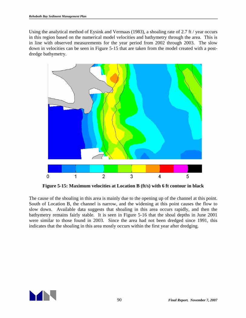
Rehoboth Bay Sediment Management Plan
90 Final Report. November 7, 2007
Using the analytical method of Eysink and Vermaas (1983), a shoaling rate of 2.7 ft / year occurs in this region based on the numerical model velocities and bathymetry through the area. This is in line with observed measurements for the year period from 2002 through 2003. The slow down in velocities can be seen in Figure 5-15 that are taken from the model created with a post-dredge bathymetry.
Figure 5-15: Maximum velocities at Location B (ft/s) with 6 ft contour in black
The cause of the shoaling in this area is mainly due to the opening up of the channel at this point. South of Location B, the channel is narrow, and the widening at this point causes the flow to slow down. Available data suggests that shoaling in this area occurs rapidly, and then the bathymetry remains fairly stable. It is seen in Figure 5-16 that the shoal depths in June 2001 were similar to those found in 2003. Since the area had not been dredged since 1991, this indicates that the shoaling in this area mostly occurs within the first year after dredging.

Rehoboth Bay Sediment Management Plan
91 Final Report. November 7, 2007
23
28
34
39
43
49
55
52
44
24
23
27
32
24
31
39
47
51
62
69
79
85
88
94
89
87
85
77
64
54
42
32
27
23
24
23
23
23
23
35
35
36
2322
23
23
24
24
25
27
46
5459376263
57
59
696767555140
35
27
222234
49
586255
48
37
3123
27
22
26
36
51
54
60
54
43
23
22
23
24
23
35
34
34
32
27
35
47
40
43
51
46
41
41
38
33
24
24
23
25
27
29
30
32
2333
23242223
22
2324
23
2224
28
39456760
69
6681
85
77776954
65
635852
47
44
373329
23
97
118
120
112
111
94
104
87
77
68
35
27
23
24
23
23
31
23
28
23
23
23
23
23
23
23
24
2928
27
27
26
25
24
242727
25232423
24
26
31
373432344247
6174
82
88
8684
7774
59
44
24
14 May 2001
rker #17
2001
31 May
2001
PVC Ma
rker #
17
Marker
#13
Flash
Green
31 May
2001
Figure 5-16: June 2001 USACE survey Location B: Pullover
5.4.3 Location C: Massey’s Landing Location C just north of Massey’s Landing, shoals for similar reasons as Location B. Both are areas where the narrow channel expands, and the flow slows down and subsequently deposits sediment. Both of these shoals primarily form on the flood tide, when high velocity flow is being pushed northward through narrow channels. Also similarly to the shoal at Location B, the one at Location C also primarily shoals during the first year after dredging.
746,000
747,000
5.4
6.8 6.5 5.6 6.3
7.3 7.7 6.5
5.8
5.1 6.0
6.3
5.7 4.9 5.3 6.4 6.0 5.2
4.8
5.6 5.7 4.0 2.9 1.0
5.8
6.3
6.2
6.1
6.1
6.0
6.0
5.9
5.9
5.8
5.8
5.7
5.6
5.6
5.5
5.5
5.4
5.4
5.3
5.3
5.2
3.7
3.4
5.7
6.1
5.2
6.1
4.8
4.8
4.9 4.6
4.5
5.0
6.1
6.8
6.8
7.7
7.3
6.8
6.8
6.8
6.1
6.0
5.2
5.0
4.8
5.0
5.0
5.0
4.8
4.5
4.0
3.1
2.0
2.7
1.4
2.6
3.6
4.0
4.7
5.3
5.5
5.8
6.2
6.8
6.5
7.4
8.7
9.4
9.9
10.5
10.3
9.9
8.6
6.0
5.1
4.8
5.3
5.2
5.4
3.4
5.5
7.4
8.3
9.2
10.3
11.2
.41
12.0
14.4 15.0 14.7 15.0 14.8 14.3 13.2 10.8 8.6 5.8
4.3
7.1
8.6
7.0
7.6
8.6
9.5
11.2
11.2
10.6
10.1
11.9
13.2
13.3
12.7
11.9
8.8
6.8
5.7
7.6
9.5
6.2
1.9
2.4
1.5
13:33:40
Figure 5-17: July 2003 USACE survey collected at Location C: Massey’s Landing
Figure 5-17 shows the USACE survey of Location C taken in July 2003, one year after DNREC dredged Massey’s Ditch in 2002. This shows values of about 5.3 ft below MLW. Using peak flood velocities which are shown in Figure 5-18 as input to the model outlined by Eysink and

Rehoboth Bay Sediment Management Plan
92 Final Report. November 7, 2007
Vermaas (1983), the shoaling rate for this area is 2.3 ft/year which is similar to what is observed in the surveys.
Figure 5-18: Maximum velocities at Location C (ft/s) with 6 ft contour in black
Similarly to the shoal formed at Location B, the one at Location C also stabilizes within that first year. This is shown in Figure 5-19, in which depths in the region are similar if not deeper that those observed in 2003, one year after dredging. This indicates that if a constant navigation channel of 6 ft depth below MLW is to be maintained, dredging will likely have to be performed every year.

Rehoboth Bay Sediment Management Plan
93 Final Report. November 7, 2007
56 42 46
41 37 37 47 57 56 64 77 81 68 57 52
46
39 34 36 39 41 46
49
43 37 26
28
33
38
39
43
44
43
45
49
48
56
60
62
63
66
77
78
70
56
54
43
45
35
37
36
40
52 46 41
43 50 57 71 85
97
99 98 95 90 77 68
59
63 58 54 50 46 41 34 32
26
3
54
43
32
37
41
44
51
53
44
55
60
57
47
39
31
33
38
43
40
51
50
52
29
45698285
8700
709111312
513
714
514
313
813
9
135
10411
010
910
298
9010
611
012
113
111
47868
485166856225
Buoy #18 Ebb Tide 31 May 0
1
Figure 5-19: June 2001 surveys collected at Location C: Massey’s’ Landing
5.4.4 Location D: Middle Island Shoal The shoal found at location D (just north of Middle Island) forms due to the high velocities coming through the channel on the ebb tide. Unlike the shoals at Locations A, B, and C, this shoal forms in a crescent shape extending south and east of the Massey’s Landing Marina. Comparison of available surveys in 2003 and 2004 indicates that the shoal’s growth was not as fast as the growth found at Shoals B and C, and that eastward growth of the shoal continued after the first year.
LABE
NSPOINT
4.6
6.5
7.4
8.2
8 3.89.39.0
10.610.89.79.59.89.58.58.07.1
6.0
10.8
10.8
10.3
10.4
9.5
9.6
9.0
9.8
10.4
9.4
8.8
8.8
8.4
8.3
8.3
8.0
7.6
.5 0
9.7
11.19.47.96.56.05.35.87.28.09.0
10.010.810.611.611.610.810.210.912.413.412.410.25.4
7.2
11.8
12.4
13.3
13.9
14.5
14.3
14.3
12.8
12.0
11.4
9.2
8.3
7.7
6.4
5.1
2.9
1.1
3.0
4.1
4.8
5.8
6.0
6.9
7.2
7.8
7.2
5.7
3.8
3.2
2.8
3.5
3.6
1.92.02.32.6
2.93.54.14.45.4
10.19.78.87.66.65.7
6.04.02.52.03.3
4.35.36.97.68.9
10.311.6
12.212.712.6
2.8
7.8
9.8
11.2
12.1
12.5
12.3
12.1
11.3
11.1
10.9
9.0
8.1
7.3
6.5
5.3
4.7
4.1
3.3
2.7
2.2
1.3
2.0
5.7
7.9
8.3
7.7
6.3
5.7
5.1
3.6
2.9
3.7
3.3
3.4
3.3
3.6
7.6
6.4
4.7
5.8
6.1
6.8
6.6
8.3
9.8
11.3
13.1
14.5
16.4
18.4
19.6
20.4
18.8
16.8
14.4
5.2
3.9
3.3
2.1
2.0
1.9
3.7
4.4
5.8
7.2
8.5
9.7
10.1
9.8
10.5
10.0
9.7
8.9
6.2
1.8
5.2
8.5
12.2
14.9
16.9
17.3
16.2
13.6 11.4
8.2
1.4
2.0
3.3
4.6
5.4
6.2
6.8
7.3
9.0
10.2
11.1
9.8
8.9
7.9
6.8
5.1
4.8
2.8
-0.3 2.2
1.8
1.4
1.7
1.5
2.9
3.6
4.2
4.9
5.8
7.3
8.3
9.0
10.0
9.5
9.0
8.4
7.8
7.7
6.5
5.2
4.4
3.6
2.5
1.9
2.5
1.6
2.1
2.6
3.0
3.3
3.5
1.5
1.6
2.3
2.7
4.0
7.0
8.7
9.5
10.3
11.0
11.6
11.9
11.2
10.5
10.0
9.1
7.9
5.6
3.9
1.7
1.2
2.1
3.5
6.8 8.4 8.0 9.0 9.7 11.1 12.0 13.3 14.0 13.8 13.3 12.1 10.2 8.1 3.3 1
109.7
8.9
8.4
4.1
#21
y 2003
Red Nun
Flood Tide
2 July 2003
2 July 2003
Marker #19
2 July 2003
Marker #17B
Figure 5-20: July 2003 USACE Survey at Location D: Middle Island Shoal
The area affected the most within the first year, seems to be along the south-eastern edge of the shoal. Figure 5-21 shows the maximum velocities in the region of Location D. This shows that

Rehoboth Bay Sediment Management Plan
94 Final Report. November 7, 2007
the velocities significantly slow along this edge, indicating that this is the region of shoaling. Using these velocities in the model (Figure 5-21) outlined by Eysink and Vermass (1983), shoaling rates of 3.4 ft/year were predicted for location D. However, sedimentation is not over the entire channel width, but along the leading edge of the shoal.
Figure 5-21: Maximum velocities in Location D (ft/s) with 6 ft contour in black
The shoal tends to smooth the edges that were created during dredging and recover its crescent shape (Figure 5-22). It is also evident that the shoal grows to its eastern and southern sides impacting the channel in these areas mostly by decreasing their width. There is insufficient survey data to know whether a stable condition with a very narrow channel between the shoal and Middle Island would develop or whether the shoal would grow indefinitely although the latter seems unlikely based on basic principles.
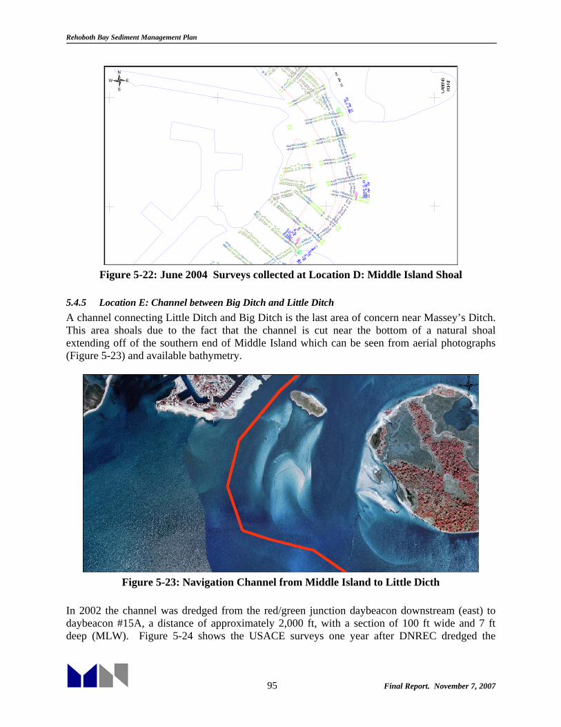
Rehoboth Bay Sediment Management Plan
95 Final Report. November 7, 2007
LABE
NSPO
INT
3.6
6.4
7.7
8.9
9.7
10.7
11.3
11.9
11.8
11.3
10.7
10.6
9.6
8.9
7.5
6.8
5.3
3.8
2.4
12.1
12.4
13.0
13.3
13.2
14.0
13.4
12.3
11.7 9.
39.
68.
37.
36.
44.
53.
1 2.6
3.3
4.4
5.5
6.5
7.2
6.5
5.9
5.6
5.3
5.0
5.1
4.6
4.4
4.1
3.9
3.7
3.6
3.5
3.9
4.7
5.5
6.1
6.6
7.6
8.4
9.0
8.3
7.2
6.4
5.4
4.8
4.1
3.3
2.9
2.7
5.0
6.4
7.7
8.7
9.6
10.3
10.3
10.1
9.8
9.5
8.5
3.4
3.3
4.1
4.7
6.0
6.9
8.1
9.1
10.2
10.1
9.0
7.7
7.2
5.8
5.2
4.2
3.7
2.7
2.8
5.0
6.5
7.6
7.9
8.0
7.2
6.1
4.8
4.0
2.3
2.8
4.0
5.1
6.1
7.5
8.0
8.5
8.4
9.6
10.0
9.8
8.9
8.2
7.2
6.3
5.2
4.4
3.6
3.0
3.6
9.1
10. 3
11. 6
11. 9
12. 2
12. 0
11. 7
11. 0
10. 7
11. 6
10. 5
9.4
3.1
4.4
5.5
6.5
7.2
6.0
5.6
4.9
4.5
4.0
3.5
3.3
3.3
3.4
3.2
3.3
3.4
5.2
7.3
862 79848.78.28.57.88.49.510. 09.
38.99.28.27.66.76.1
10. 7
10. 7
10. 9
10. 6
10. 2
9.9
9.6
9.5
9.2
8.9
8.7
8.5
8.2
8.3
8.6
8.4
8.6
8.1
7.3
7.6
7.1
68 9
7.710
. 59.68.88.26.66.55.96.77.58.59.29.79.710. 59.
410. 19.
79.9
10. 311. 111. 812. 512
. 610. 66.8
12. 5
13. 9
14. 1
13. 4
13. 0
12. 5
11. 6
10. 6
10. 0
9.5
9.4
8.1
6.7
5.9
5.0
4.4
3.7
3.5
4.2
4.9
5.3
5.4
5.9
6.4
6.7
7.9
6.7
5.6
3.8
3.0
2.83.23.
74.04.86.08.
15.02.
74.02.92.32.22.42.73.13.05.06.07.07.98.69.19.810. 811. 211. 8
11. 3
21 A
pr 0
4
Mkr
(no
numb
er)
21 A
pr 0
4
Mkr#
17B
21 A
pr 0
4
21 A
pr 0
4
Ebb
Tide
N-22
Ebb
Tide
Buoy
# C-
19
Buoy
#
21 A
pr 0
4
1 35 13.4
11.611.1
10.410.2 10.4 10.1 9.8 9.2
8.2 7.8 7.5 7.3 7.2 7.2 7.2 7.37.1
7.0 7.1 7.16.9 6.5 6.4 6.5
6.6 6.7 6.5 6.7 6.9 7.1 6.86.7
6.15.8 5.7 5.5 5.3 5.1
4.64.54.44.2 4.13.9
4.44.4
4.4
4.3
4.44.
54.
64.
74.
54.5
4.85.15.86.
57.
0
7.7
8.1
7.8
7.1
7.5
7.6
7.9
7.8
8.2
8.3
9.0
9.6
9.0
9.6
9.1
8.7
8.5
8.2
7.1
7.2
7.067
24
28.
310
.6
12.2
13.2
13.7
13.9
13.711
.8
10.7
10.39.
68.
57.
1
7.5
3.9
6.8
8.7 9.
9 10.2 10
.3 109
4.54.85.1
9.0
9.39.59.811.0
11.3
12.112.011.9
12.713.3
13.4
12.7
13.1
12.413.0
11.711.613.3
11.9
/
Figure 5-22: June 2004 Surveys collected at Location D: Middle Island Shoal
5.4.5 Location E: Channel between Big Ditch and Little Ditch A channel connecting Little Ditch and Big Ditch is the last area of concern near Massey’s Ditch. This area shoals due to the fact that the channel is cut near the bottom of a natural shoal extending off of the southern end of Middle Island which can be seen from aerial photographs (Figure 5-23) and available bathymetry.
Figure 5-23: Navigation Channel from Middle Island to Little Dicth
In 2002 the channel was dredged from the red/green junction daybeacon downstream (east) to daybeacon #15A, a distance of approximately 2,000 ft, with a section of 100 ft wide and 7 ft deep (MLW). Figure 5-24 shows the USACE surveys one year after DNREC dredged the

Rehoboth Bay Sediment Management Plan
96 Final Report. November 7, 2007
channel in 2002. This figure shows that one year after dredging there still was a relatively deep channel through this area.
3.1
3.8
7.8
1.3
3.4
3.2
6.9
4.5
2.2
2 43.22.83.4
4.25.05.77.07.78.59.28.58.27.46.96.35.74.33.83.11.82.8
3.13.03.12.92.72.62.52.22.02.01.91.91.61.41.31.1
1.2
1.11.01.01.30.91.02.72.92.13.31.13.11.21.11.61.61.81.92.12.42.52.42.72.72.62.62.62.62.52.42.62.62.32.52.32.52.32.32.22.32.32.11.8
1.2-0.61.1
1.01.21.51.71.82.02.12.32.52.82.93.53.13.43.34.04.95.76.47.48.19.39.69.39.39.19.28.67.56.96.85.95.65.45.04.74.434.6
4.85.15.55.86.46.87.38.29.09.49.6
10.18.57.86.96.86.16.05.85.85.75.35.45.04.64.53.93.93.93.63.63.73.53.33.63.32.9
2.72.72.52.32.32.3
2.12.12.02.12.12.22.22.22.2
2.22.22.2
2.42.62.9
3.02.83.03.33.53.5.5
5.45.0
4.3
3.53.43.5
3.43.5
3.43.43.53.13.23.33.33.03.43.33.53.23.43.43.53.33.43.43.1
3.32.03.13.53.73.94.2
4.95.25.05.65.4
6.16.36.26.56.97.28.38.38.48.7
8.67.46.76.35.65.75.75.65.55.14.84.54.34.23 83.4
4.03.94.1
4.24.34.85.05.05.15.35.55.75.55.36.0
6.16.97.87.88.28.08.47.36.96.35.85.54.94.53.84.03.83.53.83.93.73.83.93.93.94.24.14.23.94.1
4.04.34.14.54.6
6.05.8
6.1
6.56.87.06.97.06.7
6.1
3.3
3.23.43.93.94.6
5.25.55.36.06.46.9
7.17.57.77.77.48.1
8.18.38.48.48.48.48.58.68.78.38.57.77.77.2
7.48.9
8.88.48.17.5
6.86.0
6.05.34.94.96.3
5.85.75.55.35.04.84.34.14.03.9
3.83.93.83.83.63.63.74.675.04.9
4.84.84.74.84.23.63.63.64.04.3
4.54.75.56.3
6.97.45.34.03.83.74.0
3.83.83.73.83.9
3.73.93.63.7
3.93.7
3.44.03.63.73.83.93.8
3.63.63.53.53.63.83.5
3.53.13.02.82.72.9
2.92.8
2.82.5
3.3
3.33.53.33.43.23.03.23.2
2.72.92.62.82.71.52.72.42.62.12.72.92.52.82.62.72.72.72.7
2.83.05.67.18.08.27.86.96.05.55.04.94.84.84.95.05.25.05.04.6
4.94.74 64.7
4.64.94.75.15.35.76.05.96.46.97.48.08.68.37.5
6.64.4
3.23.01.81.63.13.03.1
3.02.9
3.23.0
3.13.13.03.23.13.13.2
3.33.43.23.43.43.5
3.0
2.11.8
4.4
6.3 6.3
6.4
6.1
6.0
6.1
6.0
6.1
5.8
5.3
5.3
5.1
4.7
3.9
3.7
3.6
3.6
3.2 2.9
2.9
2.7
2.6
2.4
2.6 3.
03.4
3.3
3.3
3.5 4.1
4.1
4.6
4.7
5.2
5.7 7.
87.3
7.5
7.8
6.7 5.8
5.3
5.2
5.0
4.8
4.7 4.
13.8
3.9
3.8
3.7 3.
33.2
2.9
2.5
2.2
2.9
2.7
2.8
2.7
2.6
3.4
2.5
2.7
-0.7
2.5
2.6
3.0
3.3
3.0
3.4
3.5
3.4
3.6
4.6
5.3
6.7
7.2
7.4
6.9
6.3
5.8
5.0
4.7
4.4
3.6
3.3
3.1
3.0
3.0
3.0
3.0
2.9
3.0
2.7
2.9
3.0
3.2
3.3
3.6
3.5
3.4
3.6
3.8
3.5
3.3
3.2
3.6 2.
93.2
2.8
3.0
2.8
2.8 2.8 2.
8
2.9 3.3
3.4
3.5 4.2 4.4 5.0
5.8
7.5
8.4 7.
86.0
5.1
4.6
4.2 3.
63.6
3.6 3.4 3.5 2.8 3.0
2.8
2.6
2.8
2.4
2.4
2.6
2.8
2.7
3.1
3.1
3.7
3.5
3.8
3.8
3.8
3.9
3.9
4.3
4.6
4.8
5.0
5.5
5.7
7.1
7.4
6.6
5.8
5.0
4.6
4.1
3.5
3.3
3.5
3.6
3.0
3.4
3.4
3.3
3.2
3.5
3.4
3.4
3.6
3.4
3.8
3.7 3.7 3.5
3.6
3.5
3.6 3.
43.4
3.3
3.4 3.2 3.5 3.4
3.7
4.0
4.4
4.9
5.3 8.5
7.5
6.8
6.0
5.7
5.3 4.
74.8 4.3
3.9 3.5
2.1
3.2 3.2
2.8 1.5
1.7
2.0
2.6
2.9
3.4
6.1
6.1
6.8
7.1
8.1
8.8
7.8
4.0
3.6
3.3
3.1
3.0
2.9
2.7
2.8
2.8
2.8
2.7
2.7
2.8
2.9
2.9
2.9
3.0
2.9
3. 2. 2.9
2.8
2.7
2.8
2.7
2.8
2.6
2.8
2.8
2.9
2.8
2.6
2.6
2.8
2.5
2.5
2.3
2.6
2.5
3.0
2.8
4.6
5.0
6.0
6.8
7.4
8.1
7.5
7.1
6.3
6.0
5.3
4.8
4.2
4.0
3.7
3.2
3.1
3.0
2.8
2.6
2.3
1.3
1.3
1.8
1.9
2.53.
23.4
3.7
3.3
3.5
3.65.
86.6
7.3
7.0
7.0
7.14.33.33 2 1
Marker #17A
2 July 2003
Marker Red/Green
Flash Red
2 July 2003
2 July
03
Marker
#27
Buoy #26.Flood Tide2 July 03
2 July 03
Marker #25
Figure 5-24: July 2003 USACE Survey of Location E: Channel between Big Ditch and
Little Ditch The maximum velocities in the region extracted from the hydrodynamic model are shown in Figure 5-25. These velocities were used in the analytical model (Eysink and Vermaas, 1983) to determine a shoaling rate for this area. This was calculated to be approximately 1.8 ft/year, which is less than in the other areas near Massey’s Ditch. Velocities in this area tend to be slightly less, and are not fully aligned with the channel on either ebb or flood tide. Unlike the areas with higher depositions like Locations B and C, the area does not seem to shoal enough to require dredging within a one year period.

Rehoboth Bay Sediment Management Plan
97 Final Report. November 7, 2007
Figure 5-25: Maximum velocities for Location E (ft/s) with 6 ft contour in black
Figure 5-26 shows the USACE surveys of Location E in June 2001, 10 years after the previous dredging. This shows more sedimentation than was present in 2003 within the channel. Depths are approximately 5-6 ft below MLW. This indicates that the sedimentation in this area of Massey’s Ditch is on a slower time scale than some of the other areas.
746,
000
747,
000
748,
000
749,
000
38
44
49
50
50
55
57
58
61
64
67
79
83
71
57
49
42
38
33
30
28
29
28
28
28
28
28
28
28
5 58 59 60 60 60 60 59 57 60 60 59 59 57 55 51 52 49 44 39 35 33 32 31 32 30 31 31 31 31 31 31 31 31 31 31 33 31 32 32 33 35 37 38 40 43 45 48 50 53 55 58 60 62 64 65 64 69 67 66 62 61 57 54 51 48 47 45 44 42 41 40 40 39 36 37 37 36 35 34 32 31
30
29
29
30
30
30
29
29
29
29
29
29
30
30
29
30
30
30
31
32
33
37
39
38
47
54
64
67
70
68
65
64
60
57
52
47
43
39
35
33
31
30
30
29
29
29
29
38
29 29 30 29 30 31 33 37 40 42 46 50 56 69 78 82 84 83 82 71 59 53 43 41 39 37 35 34 32 33 34 34 32 31 29 30 29 28 26 25 24
28
28
28
29
29
29
29
30
31
32
32
33
34
35
35
37
38
40
43
44
47
51
52
56
67
73
79
76
71
63
55
50
43
39
36
34
31
30
30
31
32
30
29
30
30
30
29
28
28
29
29
30
29
30
30
29
30
33 33 33 33 33 32 32 31 31 30 30 31 29 29 29 30 29 30 29 30 30 31 33 35 38 40 43 47 57 73 81 84 76 68 63 57 54 51 46 43 41 40 40 36 35 33 31 31 3
130
28
28
28
28
28
28
28
28
28
28
28
29
28
30
33
37
43
48
55
62
73
77
73
65
62
59
56
55
54
48
35
32
30
29
28
28
28
28
28
29
29
3 3 3 3 45
54
62
64
66
69
65
70
67
59
52
46
40
37
32
30
30
29
29
29
29
27
27
28
28
27
PVC
Mark
er #
15A
with
Rad
ar R
efle
ctor
Buoy
#16
Ebb
Tide
31 M
ay 0
1
31 M
ay 0
1
PVC
Mark
er #
17wi
th R
adar
Ref
lect
or31
May
01
PVC Marker #17A
31 May 01
with Radar Reflector
Marker Red/Green
Flash Red
31 May 01
1718181719192 12 3242 5262 8293 0323 23 23 752566 26 77 38 38 0848 27 77 36 96 35 9515 3
566 1656 97 37 57 77 8808070817 96 6574 1343 63 23 0262 6252 21918171616
343 84 34 85 15 35 65 55 15 95 86 473657 971768 28 17 5
7 07 06 6636 05 75 248
5 05 35 5586 2666 97 27 07 5707 57 17 06 77 06 464636 7656 06 16 15 85 65 34 9464 24038
333 23 1302 92927
2 32 1191817161519151616151615151515151516161516171718
5534 9
3 63 43 23 13 03 02 92 929
2 92 52 82 72 8292 8
2 62 82 72 72 62626
262 62 62625252 5
252 326293 2343 73 9
4 75 0535 65 859616062646 3666 364626 05 96 2626 36 1585 75 55 35 14 9474 4423 9373334
363 8383 9414 14 346454 64751535 55 75 96 16 36 46 66869686 55 6626 3616 1
595 65 0394 23 83 8
3 73 63 43 3323 233
333 4343 53 63 6
3 83 84 14 14 14 24 3
4 75 154
646 4666 26 2636 2
25262 52 6
313 23 53 74 0
4 74 7485 2565 7
636 66 76 9707 07 47 6
7 68 08 28079828 3
8 080817 47 06664
6 15 75 75 556
525 14 8464 3496 46 25 54 74 7443 8403 43 4353 53 332333 1313 23 63 94 6
4 54 54 44 3413 93 737363 84 04 24 55 260667 17 2633 73 03 230
3 131313 0
303 1313 23 13 1
313 03 03 027
2 9273 03 03 02 929
2 8282 72 72 62 1
2 6
24252 42 32 22 22 1
2 12 12 02 12 1
2121
2121
212 0
516 37 38181
78716 2565 1494 84 74 84850504 64545454 4
4 3464 6485 1545 75 9626 67 37 88 3
858 58 1736 5
272 7272 6262 6262 62 62 62 5
Figure 5-26: June 2001 USACE survey at Location E: Channel between Big Ditch and
Little Ditch
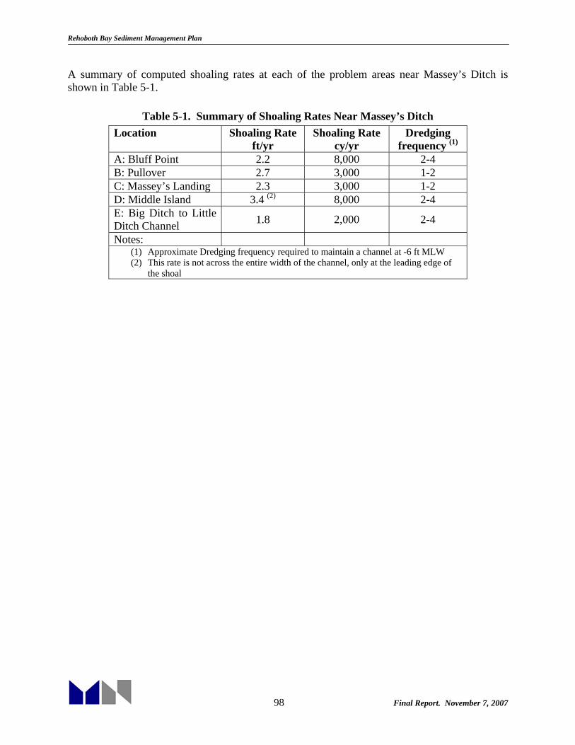
Rehoboth Bay Sediment Management Plan
98 Final Report. November 7, 2007
A summary of computed shoaling rates at each of the problem areas near Massey’s Ditch is shown in Table 5-1.
Table 5-1. Summary of Shoaling Rates Near Massey’s Ditch Location Shoaling Rate
ft/yr Shoaling Rate
cy/yr Dredging
frequency (1) A: Bluff Point 2.2 8,000 2-4 B: Pullover 2.7 3,000 1-2 C: Massey’s Landing 2.3 3,000 1-2 D: Middle Island 3.4 (2) 8,000 2-4 E: Big Ditch to Little Ditch Channel 1.8 2,000 2-4
Notes: (1) Approximate Dredging frequency required to maintain a channel at -6 ft MLW (2) This rate is not across the entire width of the channel, only at the leading edge of
the shoal

Rehoboth Bay Sediment Management Plan
99 Final Report. November 7, 2007
6. SEDIMENT MANAGEMENT The capacity remaining in existing upland disposal sites is very limited and within reach of only a few sections of all the channels in Rehoboth Bay. Finding, permitting, and constructing new upland disposal sites for future sediment management would be very difficult and costly because of the lack of available upland near existing channels. Therefore, alternative sediment management strategies in Rehoboth Bay, including potential measures to reduce dredging and/or disposal volumes, and beneficial reuse alternatives are necessary. Alternatives should also explore potential synergies between beneficial reuse alternatives and shoaling reduction measures wherever appropriate. For example, construction of new intertidal and supratidal habitat may be combined with a flow training structure, which could also provide protection to the new habitat. This section presents a general description of generic shoaling reduction measures, disposal volumes reduction measures, and beneficial reuse alternatives and their potential application to Rehoboth Bay. Section 7 discusses in more detail specific strategies that should be considered for further development and implementation. 6.1 Shoaling Reduction Measures Siltation in channels generally results from the reduction of flow velocities that arise when the channel is deepened relative to natural conditions. Shoaling in harbor basins is dictated by the following flow mechanisms:
• Mixing in the horizontal plane by flow separation in the harbor mouth • Tidal filling • Salinity (or thermal) induced density currents • Sediment-induced density currents
Shoaling reduction measures can be grouped according to the following two basic solutions (Krone, 1987):
1. KSO: Keep Sediment Out - minimize sediment flux to the harbor area 2. KSM: Keep Sediment Moving – minimize sediment settling in the harbor area
Note that both strategies are meant to reduce shoaling the channel while keeping the sediment within the natural system (i.e., no dredging and transfer outside the system required). An additional distinction can be made between passive and active measures. The former consists of non-mechanical structures (e.g., harbor entrance geometry, training structures, etc.); the latter, mechanical devices (e.g., jet pumps, water injection, etc.). The KSM strategies center on maximizing flow velocities in quiescent areas to prevent sediment from settling. The KSO strategies focus on minimizing sediment laden waters that enter harbor basins and/or navigation channels.

Rehoboth Bay Sediment Management Plan
100 Final Report. November 7, 2007
The KSO approach can involve permanent barriers (dikes or sills), harbor entrance modifications (narrow entrance, training structures, shallow entrance, horizontal eddy reduction, gates and curtains, pneumatic barriers or air curtains), and sedimentation basins or traps. KSO strategies are generally best suited to relatively quiescent harbor basins where it is not feasible to KSM. Conversely, KSM strategies are best applied to berths or channels located within or alongside relatively swiftly moving channels where a small increase in flow velocity will give rise to a significant decrease in siltation. The KSM approach can involve flow training structures (i.e., conventional dikes, submerged dikes, sills) or flow augmentation (i.e., channel realignment to take advantage of higher velocity areas, channel diversion to redirect flow towards a low velocity area, or application of scour and propeller jets that increase flow velocities mechanically). Bank stabilization is another KSM type of approach in that it keeps sediment on the adjacent banks and away from the maintained channel. This is also a potential management alternative in some of the narrow and steep sections of the Lewes-Rehoboth Canal. As explained below, there are very limited opportunities for KSO and KSM measures in Rehoboth Bay. Except in the Lewes-Rehoboth Canal and Massey’s Ditch, ambient currents are relatively slow and therefore flow augmentation through channel realignment or construction of flow training structures is difficult. KSO measures are best suited to quiescent harbor basins and not navigation channels. 6.2 Disposal Volume Reduction Measures 6.2.1 Mechanical Sediment Dewatering: Belt Press Dredging The solids content of a typical dredge discharge slurry ranges from roughly 100 to 200 g/l, as compared to the in situ solids content, which may range from 250 to 1,800 g/l, depending upon the grain size distribution of the in situ sediment (Estes et al., 2004). A relatively large area is typically required for upland placement of hydraulically dredged sediments, and these areas must be in relatively close proximity to a waterway being dredged in order to economically manage return flows. A five-acre site is considered the minimum area for an upland disposal facility to effectively manage the slurry in a typical dredging project in the Inland Bays. Dewatering and consolidation of the material, which allow for additional material lifts and increased capacity, take place slowly over time. Mechanical dewatering is an alternative to this slow process that uses special equipment to reduce the water content of the dredge slurry at the time of placement. The dewatering process (i.e., the “treatment train” per Estes et al., 2004) typically involves three phases: 1) sand and oversize removal, 2) thickening, and 3) dewatering. Each of these stages may require one or more different pieces of equipment, depending upon the specific requirements of the application and the characteristics of the sediment. Removal of sand and oversize materials is typically done using a sand screw with sump and conveyor, followed by light trash removal (bark, grass, and plastic) on a scalping screen. Oversize materials (e.g. coarse gravel, rocks, debris, and light trash) may be removed first on a grizzly or a vibrating wet screen, followed by sand removal downstream using a hydrocyclone (Estes et al., 2004). The resulting slurry normally requires the addition of a polymer and
Rehoboth Bay Sediment Management Plan
101 Final Report. November 7, 2007
thickener to coagulate the solids increase solids content and facilitate dewatering. Finally, the resulting slurry is dewatered using a centrifuge or filter press such as belt filter press. A belt filter press dewaters the material using through gravity, wedge action, and high pressure. First, water drains slurry through gravity alone, second the slurry is forced through two moving belts where water is squeezed out under low pressure as the belts converge. Lastly, the belts sandwich the now more-compressed sludge and pass over a series of rollers of decreasing size and increasing pressure to further reduce the water content (Estes et al., 2004). Belt filter presses offer continuous operation, low operator labor, reasonable capital cost, ease and simplicity of maintenance, high solids throughput, moderate footprint, high solids capture rate (i.e., low solids in filtrate), low power consumption, reasonable polymer consumption rate, high reliability and availability, and adaptability to changing process conditions (Estes et al., 2004). Typically, a belt filter press will produce a cake of approximately 40 to 50 percent solids by weight. . DNREC, in partnership with the New Castle Conservation District, has already applied this technology at Garrisons Lake near Smyrna to remove approximately 7,000-8,000 cy of silt from the lake. Finding a suitable disposal site for the dredged material had held up the project for years and belt pressing offered a feasible alternative reducing the amount of material that has to be disposed of and allowing for easier transport. In this case, the material was spread on State land controlled by the Division of Fish and Wildlife. The belt press operation was confined to an area less than 0.5 acre. Unfortunately, however, belt pressing is a relatively extensive operation: approximately $40 per cubic yard of in situ sediment in this case. Nonetheless, belt press dredging (or mechanical dewatering in general) should be considered as one of the potential sediment management alternatives for projects where neither conventional upland disposal nor beneficial reuse alternatives (discussed below) are available or are too expensive to implement. Finally, it should be noted that the type of sediments limits the applicability of mechanical dewatering. Sandy sediments (e.g., Massey’s Ditch or many of the shoaling areas in the Lewes-Rehoboth Canal) are not suitable for belt press dewatering and need to be managed with traditional dredging and disposal techniques. 6.3 Beneficial Reuse Dredged material can be a valuable resource and therefore beneficial use is sometimes a preferred method of disposal. If nothing else, it can greatly decrease the amount of traditional disposal that occurs, reducing the need for disposal sites. However, environmental impact issues would need to be addressed for beneficial uses to be approved. This may require extensive environmental impact studies. USACE (1987) identifies ten broad categories of beneficial uses, based on their functional use of dredged material at disposal sites:
1. Habitat restoration & development (wetland, upland, island, and aquatic). 2. Beach nourishment. 3. Aquaculture.
Rehoboth Bay Sediment Management Plan
102 Final Report. November 7, 2007
4. Parks and recreation. 5. Agriculture, forestry, and horticulture. 6. Strip mine reclamation and solid waste management. 7. Shoreline stabilization and erosion control. 8. Construction and industrial use (including port development, airports, urban, and
residential). 9. Material transfer (fill, dikes, levees, parking lots, roads). 10. Multiple purpose.
A basic description of the relevant categories as well as a general assessment of their potential application within a sediment management plan for Rehoboth Bay is presented in the following paragraphs. 6.3.1 Habitat Restoration & Development Habitat restoration strives to bring the existing ecosystem back to its original state or to improve it to a condition as close as possible to the original. Habitat development refers to the establishment and management of a new productive habitat. Sometimes habitat restoration/development can mean the replacement of one desirable habitat with another, which may be a contentious issue, particularly since it is difficult to measure the relative value of each habitat. A typical example would be changing aquatic or marine habitat to an emergent wetland. According to USACE (1987) four general habitats are suitable for restoration or development using dredged material:
1. Wetlands. Wetland habitat is a very broad category of periodically inundated communities, characterized by vegetation which survives in wet soils. These are most commonly tidal freshwater and saltwater marshes, relatively permanently inundated freshwater marshes, bottomland hardwoods, freshwater swamps, and freshwater riverine and lake habitats. This study focuses on the potential to restore tidal saltwater marshes in Rehoboth Bay.
2. Upland. Upland habitat includes a very broad category of terrestrial communities,
characterized by vegetation which is not normally subject to inundation. Types may range from bare ground to mature forest. Upland habitat restoration is not a likely dredged sediment management alternative in the Inland Bays.
3. Aquatic. Aquatic habitats are typical submerged habitats extending from near sea, river,
or lake level down several feet. Examples are tidal flats, oyster beds, seagrass meadows, fishing reefs, clam flats, and freshwater aquatic plant beds. As discussed below, the only aquatic habitat restoration alternative that lends itself to use with the relatively fine sediments available within Rehoboth Bay is filling of existing anoxic holes, particularly within quiescent dead-end canals. Other types of bottom restoration would require coarser sediments.
4. Island. USACE (1987) defines islands as upland and/or high zone wetland habitats
distinguished by their isolation and particular uses, and completely surrounded by water

Rehoboth Bay Sediment Management Plan
103 Final Report. November 7, 2007
or wetlands. In this study restoration of wetland islands was specifically considered (e.g., Marsh Island in Rehoboth Bay).
Wetlands (Saltwater marshes) The use of dredged material as a substrate for marsh development offers a beneficial reuse alternative to other open-water or upland disposal options. After decades of experience with wetland restoration the techniques are now sufficiently advanced to design and construct productive systems with a high degree of confidence (USACE, 1987). Marsh development or restoration as a disposal alternative can generate strong public & institutional support, particularly compared to other options that do not include habitat improvements. This should be especially true in coastal Delaware where more than 2,000 acres of tidal wetlands have been lost over the past century in the Inland Bays, or about a quarter of the original habitat (Inland Bays Estuary Program, 1995). Dredged material may be used to bring degraded wetlands up to the appropriate elevation so the tidal cycle has the desired effect. Furthermore, dredged material can be used in combination with other erosion control measures such as low-profile rock revetments or sills as a barrier to allow vegetation to grow or to stabilize an eroding wetland shoreline. Rock revetments (as compared to vertical seawalls) also allow for the creation of habitat in the intertidal zone and generally do not increase erosion next to adjacent unprotected shorelines. Recent shore-erosion control demonstration projects sponsored by DNREC and involving use of rock structures at Herring Creek/Angola Beach (1990), Mulberry Knoll/Love Creek (1991) and Rehoboth Bay/Camp Arrowhead (1991-92) are shown in the pictures below. These projects have been relatively successful in creating marsh habitat and controlling erosion (McNally, 2007). Figure 6-3, taken from DNREC’s undated publication entitled “Erosion Control: A Shorefront Property Owners Guide”, shows how a combination of rip-rap and vegetation at Camp Arrowhead can be used effectively to provide shoreline stabilization. On the other hand, using dredged material for habitat creation, particularly wetland restoration, can turn out to be a relative expensive alternative due to the extensive planning and design required, the more precise placement of material that is needed and the relatively high cost of additional sediment containment and erosion control measures (e.g., rip rap revetments).

Rehoboth Bay Sediment Management Plan
104 Final Report. November 7, 2007
Figure 6-1: Shore-erosion Control Structures Near Mulberry Knoll in Love Creek
Figure 6-2: Shore-erosion Control Structures at Camp Arrowhead in Rehoboth Bay

Rehoboth Bay Sediment Management Plan
105 Final Report. November 7, 2007
Figure 6-3: Shore-erosion Control Structures at Camp Arrowhead in Rehoboth Bay
Figure 6-4: Shore-erosion Control Structures at Angola Beach in Herring Creek

Rehoboth Bay Sediment Management Plan
106 Final Report. November 7, 2007
Thin-layer Spraying Salt marshes must accrete or accumulate material on their surface at a rate equal to the rise in sea level in order to sustain themselves. Otherwise marshes are more frequently inundated by tides, and marsh vegetation can no longer survive. Wetland resources in the U.S. are showing signs of stress due to rising sea levels. Degradation and complete loss of large areas of wetlands to submergence have been documented in the Chesapeake and Delaware Bays (Kearney, 2002). One way to restore wetlands is to increase the elevation of the existing marsh in a manner that does not destroy the existing vegetation. This may be accomplished using a dredging and disposal technique known as spray dredging. This method, which consists of spraying a thin layer of dredged sediment over marshes typically adjacent to the dredged channel, was developed for use in the Louisiana coastal wetlands where oil and gas development required construction and maintenance of extensive canals cut through marshes. In theory, the sediment can be sprayed directly over the marshes in a layer thin enough to prevent any significant damage to the vegetation. A number of projects using this technique have now been successfully completed through the country. One company in particular, Aztec Dredging, has been performing this type of dredging for years. Apparently, Aztec has a patent on a high-pressure nozzle that allows for a fine mist of sediment to be distributed over a wide area. Their system, which is portable, also allows for the slurry to be accurately regulated and controlled. Thin-layer spraying may also be suitable for marshes that have suffered Sudden Wetland Dieback (SWD). SWD is characterized by the rapid death of at least the above ground parts of saltmarsh vegetation or its failure to grow during a single or multiple growing seasons and it may also result in the complete death of saltmarsh vegetation (Bason et al., 2007). SWD, which was first reported in Delaware’s Inland Bays in 2006, may cause the loss or conversion of large areas of saltmarsh to mudflat through erosion or submergence. According to Bason et al. (2007) the cause of SWD remains unknown although the cumulative effects of multiple environmental stressors including rising sea levels, increased nutrient levels, and hydrologic alterations may be influential. Recent data actually suggest that some marshes may not be able to keep pace with sea-level rise and that certain marshes of the Inland Bays are becoming submerged and starting to break up (Bason et al, 2007). Additional physical and biological investigations may be needed to further evaluate the acceptability of thin-layer disposal for Delaware’s Inland Bays. Aquatic Habitat According to USACE (1987) aquatic habitat development is the establishment of biological communities on dredged material at or below mean tide in coastal areas, and in permanent water in lakes and rivers. Potential developments include such communities as tidal flats, seagrass meadows, oyster beds, clam flats, fishing reefs, and freshwater aquatic plant establishment. However, most of these uses require relatively coarse sediments (e.g., gravel and rock for the establishment of artificial reefs or coarse sand berms for aquatic habitat and shoreline protection).

Rehoboth Bay Sediment Management Plan
107 Final Report. November 7, 2007
Filling of Anoxic Holes There is, however, one potential aquatic habitat restoration in Rehoboth Bay: filling of anoxic holes dredged in the 1960’s to elevations significantly deeper than adjacent channel/creek depths in Bald Eagle Creek (Torquay Canal). Depths within Bald Eagle Creek and Torquay Canal average seven feet deep with holes 10-18 feet deep. Hypoxia and anoxia frequently occur in the summer months within this canal. Organic matter builds up in the holes then breaks down, forming hydrogen sulfide gas. These conditions lead to fish kills if sulfide concentrations are mixed through the water column (e.g., during a storm). Apparently aerators installed to reduce stratification and alleviate low dissolved oxygen have had no significant beneficial effect (Luther et al., 2004, Scarborough et al, 2004). Filling the holes with dredged material appears to be the best option at this point. Potential sources of sediment and storage capacity are discussed in Section X below. Filling of Dead-end Canals Numerous dead-end canals were created during the 1960’s and 1970’s as part of residential development projects that tried to maximize waterfront land. These canals experience poor circulation and flushing, excessive nutrients, low dissolved oxygen levels, hydrogen sulfide, fish kills, etc. In addition, some of these canals are not used for navigation and may actually be nuisance to adjacent residents because of poor water quality conditions. Therefore, they could theoretically be filled and converted back to intertidal wetlands or even upland habitat. As discussed below, most of these areas are relatively small and would not offer a stand-alone sediment management alternative. However, this option may be used in combination with others to improve the overall sediment management strategy in Rehoboth Bay. Island Restoration Island restoration is also an alternative that might be particularly suitable as a beneficial reuse of dredged sediments in Rehoboth Bay. As explained in Section 2.2.5, several islands have either completely disappeared (e.g., Piney Islands) or severely eroded (e.g., Marsh Island). As explained in more detail below, these islands could at least be partially restored with dredged sediments. Islands are especially important as nesting habitat for birds. Islands offer protection from ground predators, seclusion from man, and nesting substrates similar to those found in traditional nesting sites. Birds are especially vulnerable during the nesting season when they concentrate for several months in colonies and remain in them until their chicks have fledged (USACE, 1987). It should be noted, however, that island restoration may also require construction of extensive sediment containment and shore-erosion control structures which may make this sediment management approach very costly. Island restoration has already been proven to be very successful in several projects in the U.S. The Army Corp of Engineers has provided habitat incidental to their dredging and disposal activities since the agency first created dredged material islands. A notable recent example is the Poplar Island Environmental Restoration Site in Chesapeake Bay. In 1847, Poplar Island
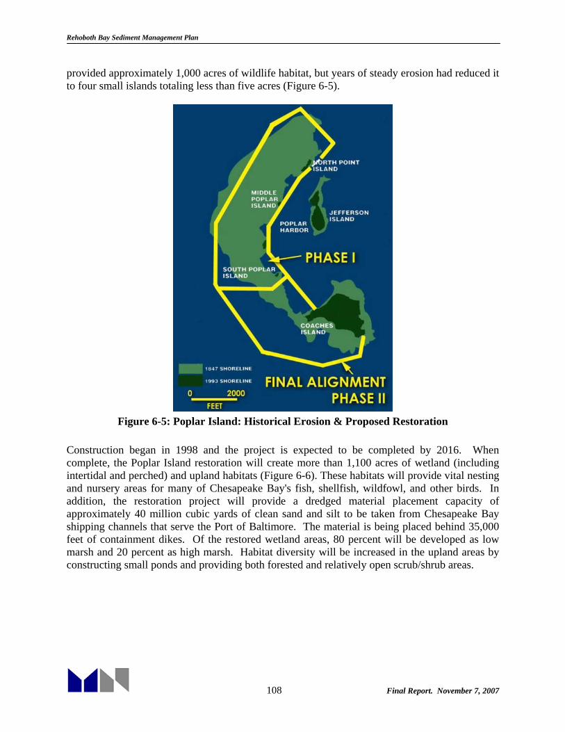
Rehoboth Bay Sediment Management Plan
108 Final Report. November 7, 2007
provided approximately 1,000 acres of wildlife habitat, but years of steady erosion had reduced it to four small islands totaling less than five acres (Figure 6-5).
Figure 6-5: Poplar Island: Historical Erosion & Proposed Restoration
Construction began in 1998 and the project is expected to be completed by 2016. When complete, the Poplar Island restoration will create more than 1,100 acres of wetland (including intertidal and perched) and upland habitats (Figure 6-6). These habitats will provide vital nesting and nursery areas for many of Chesapeake Bay's fish, shellfish, wildfowl, and other birds. In addition, the restoration project will provide a dredged material placement capacity of approximately 40 million cubic yards of clean sand and silt to be taken from Chesapeake Bay shipping channels that serve the Port of Baltimore. The material is being placed behind 35,000 feet of containment dikes. Of the restored wetland areas, 80 percent will be developed as low marsh and 20 percent as high marsh. Habitat diversity will be increased in the upland areas by constructing small ponds and providing both forested and relatively open scrub/shrub areas.

Rehoboth Bay Sediment Management Plan
109 Final Report. November 7, 2007
Figure 6-6: Poplar Island Restoration Project: Phase I Construction (circa 2000)
6.3.2 Beach Nourishment Beach nourishment can be used to enhance the beach profile and moderate the wave climate at the shoreline, allowing for better stabilization and coast protection. In addition, beach nourishment can improve recreational beaches by making them larger or keeping them from eroding. Berm creation from bottom discharge of hopper dredges can also be used to modify the wave climate and stabilize the shoreline. However, this alternative typically requires suitable sandy sediments with only a small percentage of fines which are only available at specific locations in Rehoboth Bay (e.g., Massey’s Ditch) and may not necessarily be sufficiently close to areas where beach nourishment would be beneficial. Therefore, as discussed below, this may be a relatively expensive alternative given the transport distances that would be involved.

Rehoboth Bay Sediment Management Plan
110 Final Report. November 7, 2007
7. SPECIFIC STRATEGIES RECOMMENDED IN REHOBOTH BAY The following paragraphs present specific sediment management strategies recommended for further development at each of the waterways maintained as part of the State Dredge Program in Rehoboth Bay. 7.1 Lewes-Rehoboth Canal As explained above, the last time the L-R Canal was dredged by the State was between 1989 and 1991 when a total of 40,000 cy were removed from seven areas along the channel between Lewes and the Henlopen Acres Marina. Other shallow areas in the Rehoboth Beach section of the canal and its confluence with Rehoboth Bay were not dredged for lack of nearby disposal areas (see Figure 3-8). The channel north of Savannah Ave bridge was more recently dredged by USACE in 2002 (see Section 3.1.1). However, current federal funding for this type of project is extremely limited and it appears highly unlikely federal funding will be available to dredge between Roosevelt Inlet and Savannah Bridge in the near future (Myers, 2007). This means that in order to maintain the L-R canal navigable, the share of dredging performed by DNREC would have to increase in the future. As explained in Section 5.1 above, tidal currents through the L-R Canal are for the most part relatively strong. However, there are a few areas where currents are reduced due to local channel geometry conditions (e.g., turning basin north of the Savannah Ave bridge) and/or increased sediment loads (e.g., mouth of Holland Glade). Some of these problem areas lend themselves to shoaling reduction measures while others would require continued dredging, albeit possibly incorporating increased beneficial reuse. A detailed discussion for each area of the canal is provided below. 7.1.1 Lewes, DE Reach Sediment dredged from the channel from Roosevelt Inlet to the TCFH bridge could continue to be placed on the existing disposal site adjacent to the east edge of the canal, as previously done by the State during the 1989-1991 project. This site is owned by the Commissioners of the City of Lewes. Project dimensions in this reach are 100 ft wide and 10 ft deep, MLW, north of Savannah Ave bridge and 50 ft wide 6 ft deep south of the bridge. Shoaling and dredging rates would depend on dredging frequency, but available data and analysis suggest that shoaling within this reach would be on the order of 5,000 cy/yr to 10,000 cy/yr. Disposal capacity does not appear to be an issue in the near to medium term. There are other potential beneficial reuse alternatives for this material, particularly since the sediment dredged in this area is mostly sand. Specifically, instead of placing the sediment at the disposal site, sand could be transported to Lewes Beach for beach nourishment purposes, similar to the material dredged from Roosevelt Inlet by the Corps. This approach, however, would significantly increase transport distance, which is already limited by the relatively coarse size of the sediments in this area, and therefore increase dredging costs. Particularly since most of the shoaling occurs in the southern half of this reach (i.e., the half away from the inlet). Nonetheless, a combination of existing dredging equipment (i.e., using one of the dredges as booster pump) or the State’s 14-inch dredge (the Broadkill) and a new booster pump, could be used to pump the sediment from Savannah Road Bridge to Lewes Beach along the canal and out onto the beach at

Rehoboth Bay Sediment Management Plan
111 Final Report. November 7, 2007
Roosevelt Inlet (roughly 2 miles). At the very least sand dredged within the reach of the Broadkill without a booster pump (0.5 to 0.75 miles) should be placed on Lewes Beach. Alternatively, sediment from the southern end of this reach (and farthest away from the inlet) could be pumped across the “island” along TCFH/Kings Hwy to reach Lewes Beach, a distance of approximately three quarters of a mile. A flexible pipeline could be installed adjacent to Route 9 and perhaps Rd 19 (Cape Henlopen Rd) could be crossed either by jacking a sleeve under the road (expensive) or building a ramp over the pipe (i.e., like a speed bump). Some of the issues associated with this approach would be the potential consequences of leaks and restricting access. Between Savannah Ave bridge and just south of the TCFH Bridge shoaling also appears to be significant, although accurate estimates are difficult because of the lack of survey data. The most recent Corps examination survey (April 1999) shows one shoal approximately 700 ft long between the two bridges and another approximately 400 ft long south of the TCFH Bridge. As explained earlier, these shoals were dredged also by DNREC during the 1989-1991 dredging project. As of 1999, although a very narrow and relatively deep (> 5ft MLW) thalweg exists adjacent to the north canal shoreline between the two bridges, the controlling depth over the defined channel footprint is less than 2 ft MLW. Similarly, the shoal south of the bridge limits available depth to approximately 3 ft MLW. It is possible that the formation of these shoals are related to flow conditions caused by the impingement of the bridge abutments, particularly the one at the location of the no longer existing railroad bridge just north of TCFH (Figure 7-1). At this location the canal is roughly 100 ft wide from bulkhead to bulkhead, and although these may increase the flow locally and actually cause a significant scour hole, it may be affecting/reducing tidal flows to the north and south which may have resulted in the observed shoals. Therefore, one possible sediment management alternative would be to completely or partially remove these abutments to streamline the flow through this area and prevent sedimentation by maintaining sediments in suspension (similar to adjacent areas of the canal to the south). This alternative, however, may be expensive to implement and the results would be very uncertain unless significant (and thus costly) additional studies are undertaken. Other than this shoaling reduction solution the alternatives are similar to that north of the Savannah Bridge, namely disposal at the existing facility or beneficial reuse through beach renourishment. Note that transport distance would be even greater from this location.

Rehoboth Bay Sediment Management Plan
112 Final Report. November 7, 2007
Figure 7-1: L-R Canal from the Savannah Bridge to the TCFH Bridge
7.1.2 Cape Henlopen State Park Reach As explained in Section 5.1 above, this reach of the canal, from the shoal south of TCFH bridge to the mouth of Holland Glade, is relatively stable and has not required dredging for decades. This condition owes to a straight canal alignment, uniform canal widths, and relatively fast tidal currents, all of which are not conducive to shoaling. Nonetheless, should dredging be required within this reach of the L-R Canal in the future, it would be difficult to find an upland disposal site within the reach of DNREC’s dredging equipment, even if one or two booster pumps were used. The disposal site previously used across from Henlopen Acres Marina (Mr. Anderson’s property) is no longer available and new sites are unlikely. One possible beneficial reuse in this area, depending on sediment characteristics, would be thin-layer spreading over the adjacent marshes of the Cape Henlopen State Park, which as shown earlier in Section 2.2.5, have already been affected by Sudden Wetland Dieback. 7.1.3 Henlopen Acres Reach There are three areas that appear to be more prone to shoaling in the vicinity of Henlopen Acres: (1) the mouth of Holland Glade, (2) the entrance to the North Shore Yacht Basin, and the area in the vanity of the Henlopen Acres Marina. These three areas were dredged as part of the 1989-91 DNREC project and have not been dredged since then. It is unclear when they were dredged prior 1989-91, but data suggest it was in the 1960’s. As of April 1999, the controlling depth just north and south of Holland Glade was less than 4 ft MLW and 4-5 ft MLW, respectively. On the other hand, depths at the mouth of the North
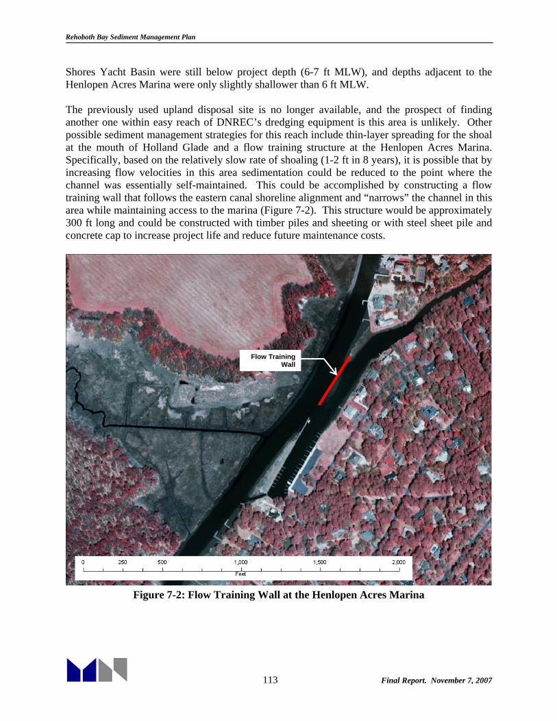
Rehoboth Bay Sediment Management Plan
113 Final Report. November 7, 2007
Shores Yacht Basin were still below project depth (6-7 ft MLW), and depths adjacent to the Henlopen Acres Marina were only slightly shallower than 6 ft MLW. The previously used upland disposal site is no longer available, and the prospect of finding another one within easy reach of DNREC’s dredging equipment is this area is unlikely. Other possible sediment management strategies for this reach include thin-layer spreading for the shoal at the mouth of Holland Glade and a flow training structure at the Henlopen Acres Marina. Specifically, based on the relatively slow rate of shoaling (1-2 ft in 8 years), it is possible that by increasing flow velocities in this area sedimentation could be reduced to the point where the channel was essentially self-maintained. This could be accomplished by constructing a flow training wall that follows the eastern canal shoreline alignment and “narrows” the channel in this area while maintaining access to the marina (Figure 7-2). This structure would be approximately 300 ft long and could be constructed with timber piles and sheeting or with steel sheet pile and concrete cap to increase project life and reduce future maintenance costs.
Figure 7-2: Flow Training Wall at the Henlopen Acres Marina
Flow Training Wall

Rehoboth Bay Sediment Management Plan
114 Final Report. November 7, 2007
7.1.4 Rehoboth Beach Reach South of Henlopen Acres controlling channel depths are relatively stable (no dredging in the last few decades) at 5-6 MLW until reaching the Route 1A drawbridge. Between this bridge and the Route 1bridge to the south, controlling depths are reduced to less than 3 ft MLW over a stretch roughly 1,500 feet long. This area was permitted for dredging by DNREC in 1989-91, but because of the lack of a nearby upland disposal site it was never dredged. As explained above, hydrodynamic conditions in this area (a straight channel and relatively fast flows) should not be conducive to shoaling. However, hydraulic impacts from the bridge abutments and, more likely, erosion of the relatively high and steep banks has contributed to shoaling over the years. A potential sediment management alternative in this area would be to stabilize the banks of the canal using a rip-rap revetment. This work would be similar to the bank stabilization project now under construction by DNREC in the Assawoman Canal. The revetment could be designed to reduce shoaling in two ways: keeping sediment out of the system by reducing bank erosion and increasing flows by restoring the previously narrower canal width. Alternatively, sediment dredged form this area could be transported to the Torquay Canal in Bald Eagle Creek, which was originally considered as a disposal site but never used in the 1989-91 dredging project. The area to be filled is approximately 13 acres and was originally excavated by the owners, the great South Beach Improvement Company, for the construction of the adjacent housing development. Filling of the dead end canal to depths more in line with the rest of the creek would potentially restore this aquatic habitat and eliminate the existing low dissolved oxygen and high sulfide gas problem which has lead to recent fish kills in this area. The estimated capacity for this site is roughly 60,000 cy based on survey data provided by DNREC and a top fill elevation of -8 ft MLW. More accurate fill capacity estimates would require a more detailed survey than the one presently available. It should also be noted that it would be difficult, if not impossible, to reach Bald Eagle Creek from this segment of the L-R Canal. Depending on the chosen pipeline alignment, the distance to cover may be as much as 1.5 miles (1 mi to the south along the canal and 0.5 mi over land). An all-water route along the canal into Rehoboth Bay and up through Bald Eagle Creek would be more than 3 miles long which does not seem practical. Dredging of the mouth of Bald Eagle Creek may also be required in order to remove the shallow “sill” and improve flushing in the Creek and Torquay Canal. Any sediment dredged from this area would also be placed in the deep holes. A better beneficial reuse option given the sandy nature of the sediments might be to pump the sediment along Route 1A to Rehoboth Beach (approximately 1 mile from the Route 1A bridge) where it could be used as beach nourishment material. 7.1.5 Thompson Island Reach The latest condition survey from April 1999 shows that from the Route 1 bridge to the southern end of the canal just north of Thompson Island controlling channel depths gradually increase from less than 4 ft below MLW to 5-6 ft below MLW. However, depths decrease again

Rehoboth Bay Sediment Management Plan
115 Final Report. November 7, 2007
significantly between the Thompson Island jetties, where the controlling depth goes from roughly -5 ft MLW to less than -3 ft MLW at the southern tip of the jetties near channel buoys #1 and #2. Farther south into Rehoboth Bay depths increase to 5-6 ft below MLW (approximately 800 ft south of the jetties) and according to available surveys remain within that range until the channel approaches the northern end of the Massey’s Landing channel near Bluff Point. This area of shoaling was also permitted for dredging as part of the DNREC’s 1989-91 dredging project, however, as in the case of the shoals near Route 1A/1, lack of a convenient disposal site prevented the dredging in this area. As explained above, sediments within this shoal are finer than in other areas of the L-R Canal (more than 40% silt & clay). Nonetheless, these sediments are well-suited for marsh restoration. In fact, the marsh west of the jetties, which as described in Section 2.2.5 has eroded more than 300 ft over the last century resulting in a loss of approximately 14 acres, would be an ideal location for marsh restoration using sediment dredged from this shoal. Preliminary estimates indicate that as much as 100,000 cy of sediment could be placed within this area. However, it is very likely that some type of shore-protection feature (e.g., a rip-rap revetment) would be required along the southern edge of the new marsh to prevent further erosion (Figure 7-3). Alternatively, a low relief timber piling wall, similar to the example shown in Figure 7-4, could be used instead to reduce the footprint of the structure and possibly reduce costs, although rip-rap may be the preferred environmental alternative. As shown in Figure 7-3, a line of protection could be constructed along the exposed perimeter of the marsh, either as a continuous, low-relief, structure or with gaps, to allow for water exchange. Sediments dredged from the channel would be placed at intervals driven by channel maintenance requirements (as frequently as every year depending on equipment availability and dredging schedule for other projects in the Inland Bays). Maintenance dredging volumes of 2,000 to 4,000 cy/yr should be expected in this area depending on dredging frequency and dredge cut. Given that controlling depths farther south along the channel through Rehoboth Bay are 5 to 6 ft MLW, it is recommended that the channel be dredged to 6 ft MLW.

Rehoboth Bay Sediment Management Plan
116 Final Report. November 7, 2007
Figure 7-3: Thompson Island Marsh Restoration
Figure 7-4: Example of marsh protection using a low-relief timber wall (Duck, NC)
Existing Jetties
Terminal Structure
Fill with dredged sediment
R e h o b o t h B a y
Shoreline Protection Structure
Thompson Island
Land loss since 1845

Rehoboth Bay Sediment Management Plan
117 Final Report. November 7, 2007
It should also be noted that the shoaling within this reach may be partially mitigated by restoring the existing Thompson Island jetties which, as explained above, are extremely degraded. Restoring the jetties, which would be relatively expensive, would increase flow velocities through at least the northern half of the shoal and possibly reduce shoaling in that area. Nonetheless, it is expected that continued dredging would be required, particularly south of the jetties, unless these structures are extended farther south, which would be very costly. Alternatively, material dredged from this shoal could be placed in the Bald Eagle Creek holes to improve water quality as described earlier. In fact, since restoring this area with sediments dredged from other areas of the L-R Canal seems unlikely due to equipment and cost limitations, the best sediment management strategy might be to fill the holes first with sediment from the southern end of the canal and then construct the marsh restoration project at Thompson Island. 7.2 Love Creek As discussed in Section 3, Love Creek was the first project undertaken by the State’s dredging program. However, this channel has not been dredged again since 1970-71, when a channel 60 ft wide and 6 ft deep (below MSL) to the Route 24 bridge (approximately 2.2 miles) and a 30 ft wide channel 6 ft deep from the bridge to Goslee Mill (an additional 1.5 miles) was first dredged. Note that 6 ft below MSL would be roughly equivalent to 5-5.5 ft below MLW. However, DNREC does mark the deepest sections of the channel with aids to navigation (channel markers). As of 2004, according to a survey provided by DNREC, controlling channel depths range from 2 to 4 ft below MLW (see Section 5.2 for details). A -4 ft MLW channel would require roughly 60,000 cy of initial dredging and annual maintenance dredging in the order of 3,000 to 5,000 cy/yr. Unfortunately there is no practical way to reduce sedimentation in the channel other than implementing a shallower design depth (e.g., -3 ft MLW). Sediment loadings, mostly resuspension of existing Creek and Bay bottom sediments, will continue. Moreover, due to the relatively open configuration of the Creek, it is not possible to increase flows without constructing very large flow training works which would effectively channel the flow along the full length of the Creek. Only one of the disposal sites used during the 1970-71 dredging project may still be available, the one at Robinson Landing. However, this is only a few acres and would not have near enough the capacity for long-term maintenance, much less the initial dredging volume required for a -4 ft MLW channel. Therefore other sediment management alternatives have to be considered. One possibility would be thin-layer sediment spreading over the adjacent marshes, particularly along the narrower sections of the creek, where the distance from the channel to the marshes is relatively short. Farther south other beneficial reuse/marsh restoration options similar to the demonstration project built at Mulberry Knoll could be implemented. Specific areas that might be suitable for restoration include Joy Beach and Horse Island marsh. At Joy Beach there are several hundred feet of “hard” bulkheaded shoreline fronting Rehoboth Bay that could be “softened” through the construction of a fringing marsh stabilized with a low relief structure as previously discussed for Thompson Island. In addition, Horse Island marsh south of Joy Beach has eroded significantly over the last 100 years which provides another opportunity for marsh

Rehoboth Bay Sediment Management Plan
118 Final Report. November 7, 2007
restoration. These potential restoration areas are within 2,500 to 6,000 ft of the southern half of Love Creek and therefore well within the reach of existing State dredging equipment. Another potential alternative in this area is restoration of Marsh Island and Big Piney Island. As discussed earlier, Marsh Island has lost over 6 acres since 1845 and Big Piney Island lost over 8 acres and completely disappeared. The approximate footprint of these islands could be restored with material dredged from Love Creek (Figure 7-5). The island(s) would need to be protected along the north, east, and south shorelines to stabilize the new marsh and prevent future erosion. The western shoreline may only require temporary containment but not long-term protection. Like the example of Poplar Island presented above, albeit at a much smaller scale, the restoration could incorporate a variety of habitats, including upland, if that provides for better overall habitat improvements. A detailed survey of this area is necessary to develop accurate estimates, but disposal capacity for this alternative may be upwards of 100,000 cy, which would solve the disposal problem at Love Creek and potentially other channels such as the southern end of the L-R Canal or southern end of the Rehoboth Bay channel near Bluff Point at Massey’s Ditch, both of which are within 2 miles of Marsh Island.
Figure 7-5: Marsh Island and Big Piney Island Restoration
Shoreline Protection Structure
Unprotected containment Fill with dredged
sediment
Shoreline Protection Structure
Fill with dredged sediment
Marsh Island
Big Piney Island
Land loss since 1845
Joy Beach
Horse Island
R E H O B O T H B A Y
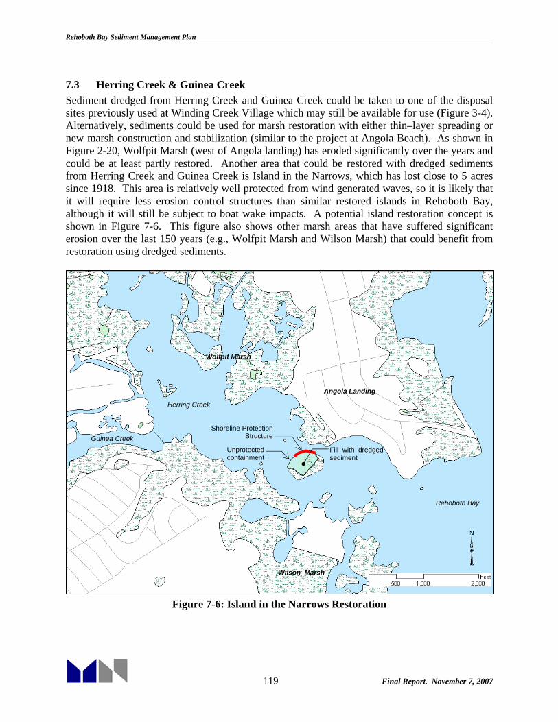
Rehoboth Bay Sediment Management Plan
119 Final Report. November 7, 2007
7.3 Herring Creek & Guinea Creek Sediment dredged from Herring Creek and Guinea Creek could be taken to one of the disposal sites previously used at Winding Creek Village which may still be available for use (Figure 3-4). Alternatively, sediments could be used for marsh restoration with either thin–layer spreading or new marsh construction and stabilization (similar to the project at Angola Beach). As shown in Figure 2-20, Wolfpit Marsh (west of Angola landing) has eroded significantly over the years and could be at least partly restored. Another area that could be restored with dredged sediments from Herring Creek and Guinea Creek is Island in the Narrows, which has lost close to 5 acres since 1918. This area is relatively well protected from wind generated waves, so it is likely that it will require less erosion control structures than similar restored islands in Rehoboth Bay, although it will still be subject to boat wake impacts. A potential island restoration concept is shown in Figure 7-6. This figure also shows other marsh areas that have suffered significant erosion over the last 150 years (e.g., Wolfpit Marsh and Wilson Marsh) that could benefit from restoration using dredged sediments.
Figure 7-6: Island in the Narrows Restoration
Shoreline Protection Structure
Unprotected containment
Fill with dredged sediment
Wolfpit Marsh
Angola Landing
Herring Creek
Guinea Creek
Rehoboth Bay
Wilson Marsh
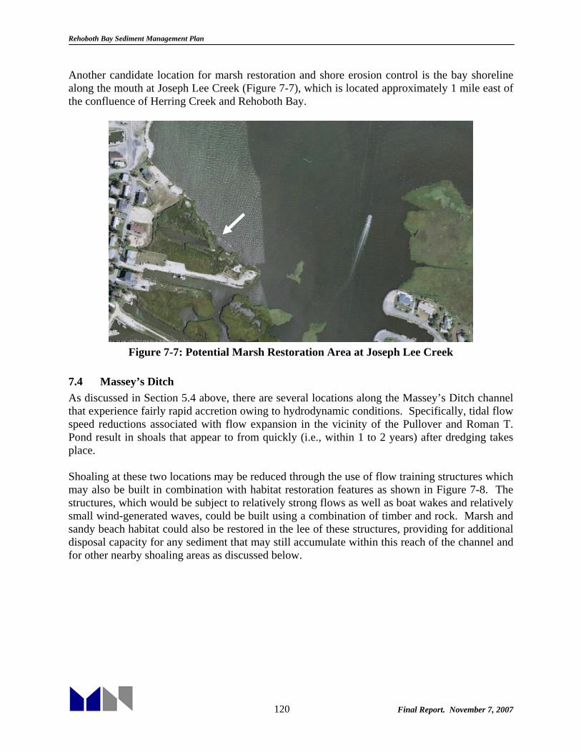
Rehoboth Bay Sediment Management Plan
120 Final Report. November 7, 2007
Another candidate location for marsh restoration and shore erosion control is the bay shoreline along the mouth at Joseph Lee Creek (Figure 7-7), which is located approximately 1 mile east of the confluence of Herring Creek and Rehoboth Bay.
Figure 7-7: Potential Marsh Restoration Area at Joseph Lee Creek
7.4 Massey’s Ditch As discussed in Section 5.4 above, there are several locations along the Massey’s Ditch channel that experience fairly rapid accretion owing to hydrodynamic conditions. Specifically, tidal flow speed reductions associated with flow expansion in the vicinity of the Pullover and Roman T. Pond result in shoals that appear to from quickly (i.e., within 1 to 2 years) after dredging takes place. Shoaling at these two locations may be reduced through the use of flow training structures which may also be built in combination with habitat restoration features as shown in Figure 7-8. The structures, which would be subject to relatively strong flows as well as boat wakes and relatively small wind-generated waves, could be built using a combination of timber and rock. Marsh and sandy beach habitat could also be restored in the lee of these structures, providing for additional disposal capacity for any sediment that may still accumulate within this reach of the channel and for other nearby shoaling areas as discussed below.
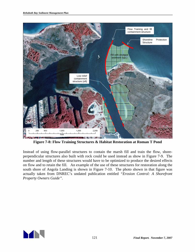
Rehoboth Bay Sediment Management Plan
121 Final Report. November 7, 2007
Figure 7-8: Flow Training Structures & Habitat Restoration at Roman T Pond
Instead of using flow-parallel structures to contain the marsh fill and train the flow, shore-perpendicular structures also built with rock could be used instead as show in Figure 7-9. The number and length of these structures would have to be optimized to produce the desired effects on flow and to retain the fill. An example of the use of these structures for restoration along the south shore of Angola Landing is shown in Figure 7-10. The photo shown in that figure was actually taken from DNREC’s undated publication entitled “Erosion Control: A Shorefront Property Owners Guide”.
Shoreline Protection Structure
Fill with dredged sediment (typ.)
Low relief containment
structure (sill)
Flow Training and fill containment structure
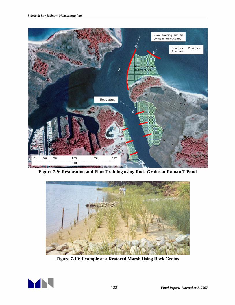
Rehoboth Bay Sediment Management Plan
122 Final Report. November 7, 2007
Figure 7-9: Restoration and Flow Training using Rock Groins at Roman T Pond
Figure 7-10: Example of a Restored Marsh Using Rock Groins
Shoreline Protection Structure
Fill with dredged sediment (typ.)
Rock groins
Flow Training and fill containment structure

Rehoboth Bay Sediment Management Plan
123 Final Report. November 7, 2007
Another shoaling area in the vicinity of Massey’s Ditch, which could be managed through the use of flow training structures, is the channel segment that skirts the west side of a sandy shoal between Massey’s Landing and Middle Island. The shoal, which extends from northwest to southeast and is also formed by flow expansion and separation effects as the tides ebbs and floods through Massey’s Ditch, grows eastward and into the channel after it is dredged, pinching it against Middle Island and narrowing it. This process does not occur as rapidly as the shoaling at the two locations above. However, according to the available Corps surveys, after only two years navigation conditions are less than ideal and maintenance dredging appears to be warranted. Figure 7-11 shows a concept for a flow training structure along the eastern edge of the channel that would theoretically prevent the eastward growth of the shoal after it is dredged. The wall could be constructed with timber, or a combination of timber and rock. Unfortunately the wall would have to completely close off the gap between Lynch Thicket and Middle Island for it to effectively train the flow. This would block direct access from Little Ditch to Massey’s Ditch and therefore have a potential impact on navigation.
Figure 7-11: Flow Training Structure at the Middle Island Shoal
Flow Training Wall
Middle Island
Little Ditch Big Ditch
Shoal

Rehoboth Bay Sediment Management Plan
124 Final Report. November 7, 2007
Note that realigning the channel in this area to be closer to the Massey’s Landing shoreline and therefore cut through the landward end of the shoal is not an effective solution. In fact, as shown the last time DNREC tried to dredge through this area, the channel would fill in very rapidly. Shoaling at north of Bluff Point in Rehoboth Bay and at the Indian River Bay channel segment that crosses from Little Ditch to Big Ditch south of Middle Island owe to naturally shallow depth in open bay waters. Unlike the three other shallow areas discussed above, these two do not lend themselves to flow training solutions or any other practical shoaling minimization alternatives. The only option that could potentially reduce dredging needs, at least at the Indian River Bay end of the channel, would be to reroute the channel through Little Ditch. However, a maintained channel from Indian River to Rehoboth Bay through Little Ditch would eliminate access to Massey’s Landing, which is considered a fatal flaw of this alternative. Moreover, maintaining a channel at -6 ft MLW around the eastern shoreline of Lynch Thicket and farther north into Rehoboth Bay may end up being more costly (i.e., more dredging required) than through Massey’s Ditch. One beneficial reuse alternative for management of sediments dredged from Massey’s Ditch, particularly the areas near Middle Island, would be transport the sediment to Bottom Hills Drain, which is located approximately 2 miles from Massey’s Ditch. Although this distance would definitely require a booster pump, it is considered a feasible alternative that would improve the aquatic habitat at Bottom Hills Drain and provide for long term storage (DNREC estimates the available capacity at 320,000 cy). Note that this alternative would (or any other that does not reduce shoaling) technically require dredging every 1-4 years, according to the shoaling estimates presented in Section 5.4, in order to maintain the specified channel dimensions (100 ft wide x 6 ft MLW). The fact that the channel has not been dredged since 2002 and that the last time it was dredged prior to that was 1991 does not mean it takes that long to shoal. Another beneficial reuse option that should be at least considered should the opportunity arise is use of the sediment for bay and ocean beach restoration. The sediments dredged from Massey’s Ditch are mostly sand and therefore ideal for this type of application. If any of the sandy beaches fronting developed communities along the northern shore of Indian River Bay between Massey’s Landing and Pot Nets Point need sand, it is possible, with the help of a booster pump, to renourish those beaches with sand from Massey’s’ Ditch. This opportunity may present itself after large storms with the potential to cause significant erosion of bay beaches. Using the sand nourishment of the ocean beaches north of Indian River Inlet would likely require double handling of the material in order to cover the distance, possibly pumping it first to Bottom Hills Drain and then from there to the beach, as has been done in the past.

Rehoboth Bay Sediment Management Plan
125 Final Report. November 7, 2007
8. SUMMARY OF FINDINGS AND ALTERNATIVES The following paragraphs summarize existing conditions, findings, and potential sediment management strategies at each of the Rehoboth Bay waterways that DNREC has been responsible for maintaining in recent years and will most likely continue to manage to some extent for the foreseeable future. Note that these recommendations, despite reducing shoaling at some locations (e.g., Henlopen Acres Marina and Massey’s Ditch), would still require dredging of 35,000 to 55,000 cubic yards per year and an initial project to dredge over 100,000 cy. This commitment would involve full-time dredging every year during the available fall window; whether or not present equipment and personnel could meet this demand still needs to be determined. Of course this estimate assumes that the channels would be regularly maintained at the selected project depth (-6 ft MLW in Federal channels, -4 ft MLW in other waterways), which has not been the case in the past. Other aspects of these recommended strategies that will contribute to cost and schedule constraints are the requirement for flow-training, fill material containment, and shore-erosion control structures. Finally, dredge equipment modifications and/or additions will likely be required (e.g., thin-layer spreading equipment, earth moving equipment, barges, etc.) 8.1 Lewes-Rehoboth Canal General • Federally Authorized Project • Approximately 9 miles long from Roosevelt Inlet (Lewes, DE) to the confluence with
Rehoboth Bay • 100 to 375 ft wide (shoreline to shoreline). Mostly between 150 and 200 ft. • Project dimensions: 100 ft wide and 10 ft deep (MLW) above the Savannah Ave bridge and
50 ft wide and 6 ft deep (MLW) from the bridge south to Rehoboth Bay. • Present controlling depths vary from -7 ft MLW north of the Savannah Ave Bridge (2006
examination survey) to less than -3 ft MLW in the Rehoboth Beach Reach. • Authorized by U.S. River and Harbor Act of 1912. Excavation of the canal began on 1913,
completed in 1916. Hydrodynamics and Sediment Transport • Tidal range over 4 ft at Lewes and less than 1.5 ft in Rehoboth Bay • Relatively strong flows, mostly over 2 ft/sec. • A few quiescent flow areas (less than 2 ft/sec) near Lewes and the Henlopen Acres Marina
leading to shoaling. • Shoaling in other areas owes to several factors: flow gradients south of the Savannah Ave
bridge, erosion and sloughing of canal slopes in the Rehoboth Beach Reach, deterioration of the jetties at Thompson Island, ebb shoal at the confluence with Rehoboth Bay.
Projected Maintenance Dredging Volumes & Frequency • Estimates are based on authorized project dimensions, including a channel depth of -6 ft
MLW.

Rehoboth Bay Sediment Management Plan
126 Final Report. November 7, 2007
• Lewes Reach: 5,000 to 10,000 cy/yr (Roosevelt Inlet not included). 2-4 year cycle. More than 90% sand.
• Cape Henlopen State Park Reach: no dredging required. • Henlopen Acres Reach: 1,000 to 2,000 cy/yr. 2-4 year cycle. Less than 30% sand. • Rehoboth Beach Reach: 2,000 cy/yr. 2-4 year cycle. More than 90% sand. • Thompson Island Reach: 4,000 cy/yr. 1-2 year cycle. 50% sand and 50% silt/clay. • An up-to-date survey would be required to estimate initial dredging volumes, but the total for
the Canal is likely to exceed 40,000 cy. Current Management & Issues • Canal north of Savannah Ave Bridge last dredged by USACE in 2002. Disposal to Lewes
CDF. • The State dredged between Lewes and Henlopen Acres Marina in 1989-91. Disposal to two
CDFs: City of Lewes’ and Mr. Andersen’s Property across from Henlopen Acres. • From Rehoboth Beach to the confluence with Rehoboth Bay the canal has not been dredged
since the 1960’s. The State planned to dredge in this area but did not for lack of practical disposal options.
• Very limited federal funding available. USACE dredging unlikely south of Roosevelt Inlet. Alternative Sediment Management Strategies Lewes Reach
• Continued disposal to City of Lewes CDF • Beach renourishment (Lewes Beach) as a beneficial reuse alternative. • Removal of Railroad Bridge Abutments to improve flow conditions and reduce shoaling.
Cape Henlopen State Park Reach
• Thin-layer spreading along adjacent marshes (if dredging is required) Henlopen Acres Reach
• Holland Glade shoal: thin-layer spreading along adjacent marshes • Henlopen Acres Marina: Flow-training wall at the to reduce shoaling
Rehoboth Beach Reach
• Bank stabilization to reduce/eliminate shoaling. • Beach nourishment (Rehoboth Beach). • Filling Torquay Canal holes in Bald Eagle Creek (seems unlikely because of transport
distance over 3 miles)
Thompson Island Reach • Marsh restoration west of the existing jetties. Will require shore protection structures. • Filling Torquay Canal holes in Bald Eagle Creek. • Restoration of the Thompson Island jetties to reduce shoaling.
Rehoboth Bay Sediment Management Plan
127 Final Report. November 7, 2007
8.2 Love Creek General • State Project • 2.3 miles from Old Landing to the Rt 24 Bridge • 200 to 5,000 ft wide • Original project dimensions: 60 ft wide & 6 ft deep (MLW) to Rt 24 and 30 ft wide & 6 ft
deep (MLW) north of Rt 24 (1.5 mi). • Approximately 115,000 cy of material were removed from the channel from July 1970 to
March 1971 (4.8 ft average cut) • Present controlling depths vary from -2 to -4 ft MLW. Hydrodynamics and Sediment Transport • Tidal range of roughly1.5 ft in Rehoboth Bay. • Very weak flows: less than 1 ft/sec. • Sediment loadings from upstream and, more importantly, redistribution of bay sediments. • A channel through this creek will always be prone to shoaling. Projected Maintenance Dredging Volumes & Frequency • Estimates are based on assumed project depth of -4 ft MLW • Roughly 60,000 cy of initial dredging required. • 3,000 to 5,000 cy/yr annual maintenance. 4-6 year cycle. Mostly silts and clays. Current Management & Issues • Channel has never been maintained since first dredged in 1970-71. • Lack of upland disposal facilities has been a problem. • Channel marking by DNREC has improved navigation considerably. Alternative Sediment Management Strategies • No shoaling reduction alternatives available due to creek and channel geometry • Thin-layer spreading along marshes adjacent to the narrow section of the creek north of
Mulberry Knoll. • Marsh restoration and shore erosion control at Joy Beach and Horse Island marsh • Island restoration: Marsh Island and Big Piney Island • Continued channel marking 8.3 Herring Creek and Guinea Creek General • State Projects • 3 miles from Rehoboth Bay to the fork (Hopkins and Burton prongs) • 2,000 to 1,000 ft wide • Hopkins Prong is 5,600 ft long; Burton 6,500 ft; Both roughly 500 ft wide • Guinea Creek is 2,500 ft and roughly 350 ft wide. • Original Project dimensions: 60 ft wide & 6 ft deep (MLW).

Rehoboth Bay Sediment Management Plan
128 Final Report. November 7, 2007
• Approximately 85,000 and 75,000 cy of material were dredged originally from Herring Creek and Guinea Creek respectively. Neither one has been maintained since.
• Present controlling depths: -3 to -4 ft MLW vicinity of Guinea Creek and Wolfpit Marsh. More than -4 ft MLW elsewhere.
Hydrodynamics and Sediment Transport • Tidal range of roughly1.5 ft in Rehoboth Bay. • Very weak flows: less than 1 ft/sec. • Sediment loadings from upstream and, more importantly, redistribution of bay sediments. • Less prone to shoaling than Love Creek because of narrower creek section. Projected Maintenance Dredging Volumes & Frequency • Estimates are based on assumed project depth of -4 ft MLW • Relatively small volume required to bring existing channel to -4 ft MLW, detailed survey
required for accurate estimate. • 4,000 to 8,000 cy/yr annual maintenance. 4-6 year cycle. Mostly silts and clays. Current Management & Issues • Channels have not been maintained since first dredged. • Lack of upland disposal facilities has been a problem. • Channel marking by DNREC has improved navigation considerably in Herring Creek. Alternative Sediment Management Strategies • Shoaling reduction alternatives very limited due to creek and channel geometry • Disposal to previously used site at Winding Creek Village which may still be available for
use • Thin-layer spreading • Marsh restoration at Wolfpit Marsh and Wilson Marsh • Island restoration: Island in the Narrows. Island restoration will also increase flows locally
and aid in shoaling reduction. • Marsh restoration and erosion control at the mouth of Joseph Lee Creek. • Expanded channel marking Herring Creek (Prongs) and Guinea Creek. 8.4 Massey’s Ditch General • Federally Authorized Project • Roughly 3 miles from Bluff Point to the intersection with the Indian River Bay Channel • 250 ft wide at Massey’s Landing. Wide open in Rehoboth Bay and Indian River Bay. • Authorized Project dimensions: 100 ft wide & 6 ft deep (MLW). • Present controlling depths: less than -5 ft MLW at critical shoaling areas as of 2003. Hydrodynamics and Sediment Transport • Tidal range increase from 1.5 ft in Rehoboth Bay to 2.5 ft in Indian River Bay • Relatively strong flows, particularly through the narrow section of Massey’s Ditch (over 4
ft/sec)

Rehoboth Bay Sediment Management Plan
129 Final Report. November 7, 2007
• Redistribution of sandy flood shoal deposits • Shoaling due to strong flow gradients (flow contraction and expansion) in the middle and
open bay conditions (slow flows) at the north and south ends. Projected Maintenance Dredging Volumes & Frequency • Estimates are based on assumed project depth of -6 ft MLW for a 100 ft wide channel • Bluff Point: 8,000 cy/yr annual maintenance. 2-4 year cycle. Sand. • Pullover: 3,000 cy/yr annual maintenance. 1-2 year cycle. Sand. • Massey’s Landing: 3,000 cy/yr annual maintenance. 1-2 year cycle. Sand. • Middle Island Shoal: 8,000 cy/yr annual maintenance. 2-4 year cycle. Sand. • Big Ditch to Little Ditch Channel: 2,000 cy/yr annual maintenance. 2-4 year cycle. Sand. Current Management & Issues • Very limited federal funding available. Future USACE dredging unlikely. • Lack of upland disposal facilities (the one used in 2002 is no longer available) • Shoaling occurs fairly rapidly (within 1 to 2 years in most areas) • Channel marking by DNREC has improved navigation but cannot prevent shoaling of sandy
sediments. Alternative Sediment Management Strategies • Flow-training structures in combination with habitat restoration at the Pullover and Massey’s
Landing to reduce shoaling. • Flow–training wall between Lynch Thicket and Middle Island • Disposal at Bottom Hills Drain • Beach restoration (ocean and bay shorelines)

Rehoboth Bay Sediment Management Plan
130 Final Report. November 7, 2007
9. REFERENCES Bason, C., Jacobs, A, Howard, A, and Tymes, M. (2007) “White Paper on the Status of Sudden
Wetland Dieback in Saltmarshes of the Delaware Inland Bays”
Bijker, E.W. (1988) “The increase of bed shear in a current due to wave motion,” Proc. 10th Int. Conf. on Coastal Eng., Tokyo. pp. 746-765
Cerco, C. F., Bunch, B. Cialone, M. A., and Wang, H. (1994) “Hydrodynamics and Eutrophication Model Study of Indian River and Rehoboth Bay, Delaware,” USACE, Waterways Experiment Station Technical Report prepared for U.S. Environmental Protection Agency, DNREC, and USACE, Philadelphia District.
Chrzastowski, M.J. 1986. “Stratigraphy and Geologic History of a Holocene Lagoon: Rehoboth Bay and Indian River Bay, Delaware”. Ph.D. Dissertation, University of Delaware.
Estes, T. J., Waugh, J., Schwartz, R. L., Green, G., Buhr, V., Braddock, B., and Detzner, H.-D. (2004). “Mechanical dewatering of navigation sediments: Equipment, bench-scale testing, and fact sheets,” DOER Technical Notes Collection (ERDC TN DOER-T7), U.S. Army Engineer Research and Development Center, Vicksburg, MS.
Eysink, W. D. and H. Vermaas (1983). “Computational methods to estimate the sedimentation in dredged channels and harbour basins in estuarine environments,” WL Delft publication no. 307.
Inland Bays Estuary Program, 1995. “Delaware Inland Bays Comprehensive Conservation and Management Plan (CCMP).”
Kearney, M.S., et al., (2002) “Landsat imagery shows decline of coastal marshes in Chesapeake and Delaware Bays.” Eos, Transactions, American Geophysical Union, 2002. 83(16): p. 173, 177-178.
Kolluru, V.S. and M. Fichera (2003). “Development and Application of Combined 1-D and 3-D Modeling System for TMDL Studies”
Krone, R.B. (1987) “Reducing Sedimentation Rates in Harbor Facilities.” In: Sedimentation Control to Reduce Maintenance Dredging of Navigational Facilities in Estuaries, Report and Symposium Proceedings, Marine Board, Commission on Engineering and Technical Systems, National Research Council, National Academy Press, Washington, D.C, p128-140.
Lean, G. H., (1980) “Estimation of maintenance dredging for navigation channels,” H.R.S. Wallingford.
Luther, G. W. III, Ma, S. Trouwborst, R., Glazer, Blickley, M., Scarborough, R. W. and Mensinger, M. G. (2004). “The roles of anoxia, H2S and storm events in fish kills of dead end canals of Delaware Inland Bays.” Estuaries 27(3): 551-560.
Mayor-Mora, D., Moretnsen, P. and Fredsøe, J. (1976) “ Sedimentation studies on the Niger river delta,” Proc. Int. Conf, Coastal Eng., Honolulu. pp 2151-2169
McKee, K., Mendelssohn, I. and Materne, M. (2004). “Acute salt marsh dieback in the Mississippi River deltaic plain: a drought induced phenomenon?” Global Ecology and Biogeography. Vol. 13(1). pp. 65-73.

Rehoboth Bay Sediment Management Plan
131 Final Report. November 7, 2007
McNally, C. (2007). DNREC Wetlands Section. Personal communication.
Mukai, A. Y., Westerink, J. J., Luettich, Jr., and Mark, D. (2002). “EastCoast 2001, a Tidal Constituent Database for Western North Atlantic, Gulf of Mexico and Caribbean Sea.” Coastal and Hydraulics Laboratory, U. S. Army Corps of Engineers. Vicksburg, Mississippi.
Mukai, A. Y., Westerwink, J. J., and Luettick, R. A. (2001). “Guidelines for Using the EastCoast 2001 Database of Tidal Constituents within the Western North Atlantic Ocean, Gulf of Mexico, and Caribbean.” Coastal and Hydraulic Engineering Technical Note CHETN IV-XX, U.S. Army Corps of Engineer Research and Development Center, Vicksburg, MS. <http://bigfoot.wes.army.mil/cetn.index.html>.
Myers, C. (2007). U.S. Army Corps of Engineers, Philadelphia District. Personal Communication.
Ocean Surveys, Inc. (2005). “Final Report: Multibeam and Single Beam Hydrographic Survey, Inlet, Flood, and Ebb Shoal Conditions, Indian River Inlet, Delaware.” Prepared for the US Army Corps of Engineers, Philadelphia. Technical Report #04FS090A
Pawlowicz, R., Beardsley, B., and Lentz, S. (2002) “Classical tidal harmonic analysis including error estimates in MATLAB using T_TIDE,” Computers and Geosciences. Vol. 28. pp. 929-937.
Raney, D.C., Doughty, J.O. and Livings, J. (1990). “Tidal Prism Numerical Model Investigation and Analysis Task of the Indian River Scour Study, Delaware”. Report prepared for the Coastal Engineering Research Center, USACE. University of Alabama Bureau of Engineering Research Report No. 500-183.
Scarborough, R.W., M.G. Mensinger and S.C. Kauffman. (2005). “Assessing Mechanical Aeration Techniques To Improve Water Quality In Torquay Canal” AERS Spring 2005 Meeting "Remote Sensing and Shallow Water Monitoring in Estuaries"
Schwimmer, R. A. (2001) “Rates and processes of marsh shoreline erosion in Rehoboth Bay, DE, USA,” J. Coast. Res., Vol.17(3). pp 672-683.
Swisher, M.L. (1982). “The Rates and Causes of Shore Erosion Around a Transgressive Coastal Lagoon, Rehoboth Bay, Delaware”, MS Thesis, University of Delaware
US Army Corps of Engineers, Philadelphia District (circa 1977-78). “Final Environmental Impact Statement, Indian River Inlet, Project Maintenance , Sussex County, Delaware.”
US Army Corps of Engineers, Philadelphia District (1975). “Delaware Bay-Chesapeake Bay Waterway in Delaware, Maryland and Virginia. General Design Memorandum: Phase 1.”
van Rijn, L.C. (1981) “Model for sedimentation predictions,” 19th IAHR congress, New Delhi,
Versar, Inc. (2002) “Methodology for Evaluation of Proposed Dredging Projects in the Delaware’s Inland Bays”. Prepared for the Division of Water Resources and Division of Soul and Water Conservation, State of Delaware, DNREC.
Williams, C. (2007) “Waterway Management Branch Scoping Paper”, DNREC Division of Soil and Water Conservation, Shoreline and Waterway Management Section.
Wong, K., and DiLorenzo, J. (1988) “The response of Delaware’s inland bays to ocean forcing,” J. Geophysical Research. Vol 93, No. C10. pp. 12,525-12,535.
Rehoboth Bay Sediment Management Plan
132 Final Report. November 7, 2007
Wong, K. and Lu, X. (1994) “Low-frequency variability in Delaware’s inland bays,” J. Geophysical Research. Vol. 99, No. C6. pp. 12,683-12,695.
WL | Delft Hydraulics, 2004. User Manual Delft3D-FLOW. Delft, The Netherlands.
U.S. Army Corps of Engineers (USACE), 1987. Beneficial uses of Dredged Material – Engineering Manual. USACE. Washington D.C. EM 1110-2-5026.
U.S. Army Corps of Engineers (USACE), 1999. Dredge Material Assessment and Management Seminar. San Diego, California.