Embed Size (px)
Citation preview

859-UK
ISOBUS Artemis
Seed Drill ControllerCalibration and Operation Manual


1
Electromagnetic Compatibility (EMC)This product complies with European Council Directive 2014/30/EU when installed and used in accordance with the relevant instructions.
PrefaceThis manual provides information about calibrating and operating the RDS “ISOBUS Artemis” system. Correct use and maintenance is important forsafe and reliable operation. Please take time to read this manual and complete appropriate training before use before using the system.
Information in this manual is correct at the time of publication. The system may vary slightly from that described herein. Topcon reserves the right toredesign and change the system as necessary without notification.
COPYRIGHT: All information contained in this manual is the intellectual property and copyrighted material of Topcon. All rights are reserved. You maynot use, access, copy, store, display, create derivative works of, sell, modify, publish, distribute, or allow any third parties access to, any graphics,content, information or data in this manual without Topcon’s written consent. And may only use such information for the care and operation of theproduct.
Warning
Please read the following important information very carefully.TERMS AND DEFINITIONS:
Console – The Topcon Agriculture console mounted inside the cab of the tractor used for primary control of the Machine.
Application – Topcon Agriculture mobile application product that allows features of Topcon Console(s) to be monitored and controlled from a Device.
Device – A mobile device (e.g. phones and tablets) on which the Application is installed and operated.
System – The combination of the Device and the Console used to control and monitor the Machine.
Machine – The combination of a tractor and associated farming implements (whether self-propelled, towed by the tractor or mounted to the tractor).
You – The person using the application to control and monitor the Machine.
Device – A mobile device (e.g. phones and tablets) on which the Application is installed and operated.
Documentation – The user documentation and manuals relating the use and operation of the covered Topcon Agriculture product, including, but notlimited to, the Console user manuals/materials and Application end user license agreement.
IMPORTANT: You must read and follow the Documentation and complete appropriate training before use. If You do not operate the Systemproperly, it may not correctly apply the Application to Your requirements. This can result in damage to property and/or malfunction of the product,death or serious injury to persons, poor yields and/or crop damage or failure. If You are in any doubt regarding any aspect of operating the System,then before commencing operation You should obtain further guidance from a suitably qualified source.
WARNING: It is YOUR responsibility to read and understand the safety sections in this book before operating the system. Rememberthat YOU are the key to safety.
PRODUCTS/MATERIALS APPLICATION: As limited by the applicable software, You are responsible for accurately entering the information required forthe Machine to apply products/materials to Your requirements, including measurement units (e.g. metric or Imperial), vehicle dimensions, rate ofapplication, vehicle speed, weight or other required input.
As limited by the applicable software, You are responsible for the calibration of the Machine and ensuring products/materials are applied inaccordance with their specifications (including wind, temperature and moisture conditions, material properties, dilution and withholding periods).
Without prejudice to the generality of the above You hereby acknowledge and agree that the system or application is not designed nor intended to:
originate variable treatment plans; or
achieve or avoid any application rate or other target setting outside application parameters, which in both cases are Your responsibility.
Failure by You to comply with the above may result in incorrect operation of the System, or injury to You or others. You should monitor at all timesthat the System is performing as required.
General SafetyDANGER! It is essential that the following information and the product-specific safety information is read and understood.
Most incidents arising during operation, maintenance and repair are caused by a failure to observe basic safety rules or precautions. Always be alertto potential hazards and hazardous situations. Always follow the instructions that accompany a Warning or Caution. The information these provideaims to minimize risk of injury and/or damage to property. In particular follow instructions presented as Safety Messages.

ISOBUS ARTEMIS - SEED DRILL CONTROLLER
2
Safety Messages and WarningsThe safety symbol is used with the relevant word : DANGER, WARNING or CAUTION. Messages marked in this way recommend safety precautionsand practices. LEARN and apply them.
DANGER : Indicates an imminently hazardous situation that, if not avoided, could result in DEATH OR VERY SERIOUS INJURY.
WARNING : Indicates a potentially hazardous situation that, if not avoided, could result in DEATH OR SERIOUS INJURY.
CAUTION : Indicates a potentially hazardous situation that, if not avoided, could result in MINOR INJURY.
Operator SafetyGood safety practices not only protect you, but also the people around you. Study this manual as part of your safety program. This safety informationonly relates to Topcon equipment and does not replace other usual safe work practices.
WARNING: Never operate the machine with any panels or safety guards removed. Any illustrations or photos in this manual thatshow panels or guards removed are solely for demonstration purposes. If the removal of panels and guards is necessary for calibrationor maintenance, they MUST be replaced before operation.
Always check that any suspended vehicle attachments or load arm(s) are lowered to the ground before beginning repair ormaintenance work on the machine.
Machine and implement parts can become hot during operation and may be under pressure. Refer to the machine/implementmanual(s).
Wear appropriate protective clothing for the task being undertaken.
Check the Machine is correctly setup/configured and ready for the intended use.
Be aware of safety instructions for/on the Machine including hazards such as crush zones.
Prevent the Machine from being accidentally started if working on it e.g. remove the ignition key, place a warning notice in the cabetc.
Check that the area of Machine operation is clear of people, animals, and obstacles and identify any other possible hazards.
Keep other persons required to be in the vicinity of the Machine fully aware of Your immediate intentions.
If a Topcon Agriculture mobile application is used to augment Your ability to perform tasks that are traditionally performed on the Console directly,then in addition to observing the above warnings and all other pre-determined site safety requirements that apply when operating a Machine fromthe Console, You must also observe the following additional requirements when operating the Machine via the Application:
WARNING: The Application must only be operated by You, the single Console operator wholly responsible for the operation of theMachine.
The Application must only be used when the Machine is not on public roads.
The Device must be affixed to a rigid mount when used inside the cab while the Machine is moving to avoid a temporary loss ofcontrol if the Device is dropped or misplaced.
The Application must only be used outside of the Machine cab when the Machine is stationary.
When operating the Application outside of the cab of the Machine You must remain within a reasonable distance such that You canreturn to the cab-mounted Console in a timely manner to resume control of the Machine under any of the following circumstances:
Battery failure on the Device
Wifi signal is lost or signal strength is too weak for proper operation
The Device is redirected to another application (e.g. a phone call is received)
The Device becomes incapacitated (e.g. device is dropped and damaged)
Any other event that causes the Device to no longer be fit for control of the Application and/or Machine.
Stand well clear of any moving parts of the Machine (e.g. hydraulic folding booms, spreader spinners, etc.) and areas of productapplication (e.g. Spray Nozzles, NH3 appliers, etc.).
The Device and Machine must be locked when not in use.
ISOBUS ARTEMIS - SEED DRILL CONTROLLER
3
1 INTRODUCTION 4
1.1 System Overview 41.1.1 System Components ...................................................................................................................... 4
1.2 Artemis Main Functions 5
2. MULTIPLE CHANNELS / PRODUCTS 6
2.1 Linked Channels 6
3. OPERATION 7
3.1 Artemis Primary Screen Pages 73.2 The Main Operating screen - Summary 83.3 Channel Selection and Status 8
3.3.1 Switching Metering motor(s) On-Off / Manual Override / Half-Width Drilling ............................. 93.4 Work Status 93.5 Setting the Application Rate 10
3.5.1 Seed and fertiliser ........................................................................................................................ 103.5.2 Pellet/ Small seed Applicator....................................................................................................... 10
3.6 Pre-start Sequence 113.7 Tramlining 12
3.7.1 Advancing the Bout Number ....................................................................................................... 123.7.2 Holding the Bout Number............................................................................................................ 133.7.3 Setting the Tramline Rhythm....................................................................................................... 13
3.8 Forward Speed Display 133.8.1 Forward Speed Alarm .................................................................................................................. 133.8.2 Simulated Forward Speed............................................................................................................ 14
3.9 Fan Speed Display 153.9.1 Set Fan Speed Alarms .................................................................................................................. 15
3.10 Hopper Level Alarms 153.11 Totals 15
4. BLOCKAGE MONITORING (OPTIONAL) 16
4.1 Blockage sensor status and alarms 164.2 Blockage sensor alarm override 174.3 Sensor Calibration 17
5. PRODUCT CALIBRATION 18
5.1 Running the test from the Cab 185.2 Running the test using the Priming Switch 195.3 Calibrating systems with ‘Accord’ type metering mechanisms. 20
6. ALARM CODES 21
ISOBUS ARTEMIS - SEED DRILL CONTROLLER
4
1 IntroductionThis manual provides operator basic instructions for both single-channel and multi-channel generic Isobus “Artemis” SeedDrill Controller application. It also includes settings in the “Drill Setup” menu accessible by the operator. Information onTechnician and Factory level settings are not included in this manual.
NOTE: Illustrations in this manual are based on a Topcon X25 terminal. The actual Artemis app screen display/button layout andfunctions may vary slightly from that shown, depending on the specific implement being controlled, the UT the app is beingrun on, its GUI and user-defined settings. If necessary, please refer to the manufacturers user manual for setup and loadingthe Artemis app on other UT’s.
1.1 System OverviewThe Artemis is an ISOBUS-compatible, monitoring and application control system for seed drills. It may be configuredwith up to 4 control channels. Forward speed measurement and cutout sensing enables full proportional control, tomaintain (within limits) a set application of one or more products irrespective of changes in forward speed.
In its simplest application, the Artemis may be setup in a single-channel configuration to control a single motor as shownin figure 1. Additional CAN modules enable multi-channel configurations for combined seed/fertiliser/pellet application(including electro-hydraulic control), to suit a wide range of drill makes and models.
1.1.1 System ComponentsThe system will vary depending on the drill make and model, but will be some combination of one or more of thefollowing,
The main electronic components are,
ISOBUS UT
ISOBUS/CAN Bridge Module – the “brains” of the system, containing the control software. It also contains the graphics(the ‘Object Pool”), for the GUI to be displayed on any ISOBUS-compliant terminal.
Motor Control (MCM) CAN Module – CANBUS interface for a gearmotor and sensors.
Applicator Control (APM) CAN Module – CANBUS interface for an Applicator system (optional).
I/O (HBM) CAN Module – CANBUS interface for other switches, sensors and actuators.
Connected via the Motor Control Module (‘MCM’)
Gearmotor –driving either single or multiple metering units.
Shaft Speed Confirmation sensor – a magnetic sensor that confirms that the motor is driving the metering unit.
Forward Speed Sensor –Speed signal sent from ISOBUS UT.
Area Cutout Switch(s) - one or two magnetic sensors or finger switch positioned to detect when the drill islowered/raised into or out of work. It can be configured to also provide the tramline advance signal.
Priming Switch – manually operates the metering motor to dispense product for calibration purposes.
Connected via the Tramline Control Module (‘HBM’)
Fan Speed Sensor(s) - a magnetic sensor on the fan drive.
Hopper Level Sensor(s) – An upper “pre-level” sensor provides an early-warning alarm, giving the operator advancenotice to refill. A lower sensor provides a second warning when the hopper is about to run out.
Tramline Advance Switch - provides the tramline advance signal (if not a function of the Area Cutout Switch).
Tramline mechanism (existing) – the solenoid or motor-type mechanisms are rewired into the HBM connection box to becontrolled by the Artemis.
Pre-emergence Markers (existing) – re-wired into the HBM connection box to be controlled by the Artemis.
Bout Marker Sensors (optional) – magnetic sensors detect when the Marker arms are lifted/lowered.

ISOBUS ARTEMIS - SEED DRILL CONTROLLER
5
Figure 1: Single-motor Artemis System
1.2 Artemis Main FunctionsThe Artemis is designed to allow automatic, variable rate control of any drill. Also it can control an auxilliary Applicatorsystem e.g. for Slug Pellets etc. You can at any time manually override the predetermined rate as field conditions require.
The basic functions are:
Variable Rate Control
Tramline Control
Forward Speed Alarms
Hopper Level alarm
Fan Speed & alarm
Information totals
The instrument has a special software routine that makes calibration of the metering unit(s) very easy. In the calibrationmode each metering unit is controlled via a ‘priming switch’ to dispense the product. During normal operation the controlsystem is started and stopped automatically via magnetic sensor(s) as the drill is put into and taken out of work.
PowerSupply
ISOBUS / CANBridge Module
‘HBM’ CANModule
Tramlinemechanisms
(existing)
TL Advance Switch
Forward Speed Sensor(Radar option)
‘MCM’ CANModule
Metering DriveGearmotor/Encoder
Fan Speed Sensor
Hopper Level Sensors
Priming Switch
Area CutoutSensor
Shaft Speed (confirmation) Sensors
HBMConnection
Box
MCMConnection
Box
Isobuscable

ISOBUS ARTEMIS - SEED DRILL CONTROLLER
6
2. Multiple Channels / ProductsThe Artemis has 4 control channels. Each motor / MCM or APM requires a control channel, therefore the number ofchannels used depends on the particular drill configuration. Here are some examples.
PRODUCT CHANNELS PRODUCT /MOTOR / METERING UNIT CONFIGURATION SCREENDISPLAY
SEED
1
1 PRODUCT
SINGLE MOTOR / METERING
1+2
1 PRODUCT
2 x SINGLE MOTOR / METERING
1
2
2 PRODUCTS
SINGLE MOTOR / METERING (SEED)
SINGLE MOTOR / METERING (FERT A)
SEED+FERTILISER 1+2
3+4
2 PRODUCTS
2 x SINGLE MOTOR / METERING (SEED)
2 x SINGLE MOTOR / METERING (FERT)
SEED+FERTILISER
1+2
3
2 PRODUCTS
2 x SINGLE MOTOR / METERING (SEED)
SINGLE MOTOR / METERING (FERT A)
1
2
3
3 PRODUCTS
SINGLE MOTOR / METERING (SEED)
SINGLE MOTOR / METERING (FERT)
SINGLE MOTOR / METERING (APPLICATOR)
EED+FERTILISER++PELLETS
1+2
3
4
3 PRODUCTS
2 x SINGLE MOTOR / METERING (SEED)
SINGLE MOTOR / METERING (FERT)
SINGLE MOTOR / METERING (APPLICATOR)
2.1 Linked ChannelsWhen a configuration requires multiple hoppers / metering units to dispense a single product, then the control channelsare linked (via the “Factory Setup” menu).
Two, three or four single, adjacent control channels may be linked in this way, and assigned a product type “Seed”, “FertA”, “Fert B or “Pellets”.
Examples:
NOTE: Linked channels are not currently recognized as linked by other software modules outside of the Artemis application. So forexample, if 4 channels are in active use but all are linked for single product application, they will be recognized as 4channels instead of effectively one channel.
If starting a Precision Farming job, the VRT (rate instructions) source is uniform across linked channels (ref. section 7.3).

ISOBUS ARTEMIS - SEED DRILL CONTROLLER
7
3. OperationThe RDS Artemis application is displayed in the Universal Terminal (UT) window. The Artemis control keys are thosewithin the UT window.
NOTE: The screens illustrated are as shown on a Topcon UT, and in this case the key locations are configurable. However, the keylayout may be different for other other terminals, and the key layout may or may not be configurable depending on theterminal. Please refer to the OEM manual for the terminal in question.
3.1 Artemis Primary Screen PagesThere are 5 primary screen pages. Press to cycle between the primary screen pages – Main, Totals, Seed Blockage,Hydraulic Functions (see Note 1) and Settings.
NOTE 1: The hydraulic functions screen is specific to particular drills and is not present unless enabled in the “Factory Setup” menu.
CAL/SETUP SCREEN (SECT. 5) SEED BLOCKAGE SCREEN (SECT. 4)
MAIN OPERATING SCREEN (SECT 3)
UK859-010.PNG
UK859-030.PNG
UK859-020.PNG
TOTALS SCREEN (SECT. 3)
UK859-230.PNG

ISOBUS ARTEMIS - SEED DRILL CONTROLLER
8
3.2 The Main Operating screen - Summary
3.3 Channel Selection and StatusThe currently selected channel is highlighted blue.
Either press , or touch a channel icon to select anotherchannel.
Repeatedly pressing cycles through the channels.
The channel icon indicates the product and the target applicationrate.
The target rate can be then set or nudged for the selected channel.
The channel icon also indicates the status of the metering motor. The motor speed is proportional to forward speed, andso when the drill is in work, the icon automatically becomes animated as the metering unit starts to turn. It also isanimated when you select the Prestart sequence, or if you have a simulated forward speed activated.
UK859-010.PNG
Channel Toggle [3.3]
Select channel. Theselected channel is
highlighted blue
Channel [3.3]
Shows the status of in-usechannels with the target
rate
Target Rate [3.5]
Shows the current targetrate of the selected
channel
Nudge Rate [3.5]
preset increments
Set target Rate [3.5]
Displays a keypad to enterthe target rate for the
selected channel
Cycle
Cycle between the MAIN,Hydraulic functions, Info
and Setup screens
Prestart [3.6]
Runs the drill at a simulatedspeed for a specified time.Used when going into work
until the target speed isreached (e.g. 8km/hr for
5secs)
Channel On/Off [3.3]
Turn the channel on / off(i.e. start/stop the metering
motor)
Tramline Advance [3.7]
Increases the tramline boutnumber by 1
Work Status [3.4]
Shows the drill in/out ofwork status and when on a
tramlining bout
Tramline Hold [3.7]
Hold the current tramlinewhen the drill islifted/lowered
Tramline Status [3.7]
Displays Target Bout,Current Bout and greenticks when tramlining.
Forward Speed [3.8]
Displays the live forwardspeed, or the simulated
speed when enabled.
Fan Speed [3.9]
Displays the live fan speedfor 1 or 2 fans.
MeteringMotor switched
OFF
Metering Motor switched ON- drill raised out of work /
stationary
Metering Motor switchedON - drill lowered in to work
and moving
Metering Motor switchedON - drill lowered in to work
but with ASC override

ISOBUS ARTEMIS - SEED DRILL CONTROLLER
9
3.3.1 Switching Metering motor(s) On-Off / Manual Override / Half-Width DrillingThe metering motor(s) can be stopped manually as desired, eg:
(i) An area of field needs further cultivation before seeding.
(ii) In the case of a front-mounted hopper, the metering motor is switched off just before the end of the bout to clear the seedthrough (the opposite of the ‘pre-start function).
(ii) You want to drill at half-width.
The currently selected channel is highlighted blue.
To switch an individual channel:
Briefly press to switch the currently selected channelOn/Off.
Alternatively, briefly touch a channel icon to switch it On/Off.
To switch all channels:
Press and hold for 3 seconds.
Half-width Drilling:
Applicable for drills configured with 2 linked channels, wherenormally for full-width drilling the motors are controlled in tandem(indicated by channel icons 1+2 and/or 3+4 being linked across thetop as shown).
When half-width application is required, either left or rightmetering motor may be switched off by briefly touching theappropriate channel icon(s).
3.4 Work StatusSensor(s) detect when the drill is raised out of work or lowered into work, and the work status is displayed at the top ofthe screen.
Drill is out of work / Metering is stopped / Area totalsaccumulation is stopped.
Drill is in work / Normal metering is in progress (unless beingmanually overridden – ref. section 3.4) / Area totals areaccumulating.
As above and also indicating a tramlining bout (ref. section 3.8).

ISOBUS ARTEMIS - SEED DRILL CONTROLLER
10
3.5 Setting the Application Rate3.5.1 Seed and fertiliser
The drilling rate is metric units only i.e. kgs/ha.
To set the Target rate for a selected channel:
First select the channel that you want to set the rate for.
Press , enter the required rate then touch “OK”.
The maximum speed to maintain the application is calculatedand displayed. Press “OK” to return to the main screen.
The system will then automatically maintain this raterrespective of forward speed (within limits).
To manually override the Rate for a selected channel:
For the selected channel, at any time you can adjust therate up or down in 5% increments to suit field conditions,up to a maximum ±50% from the target rate.
Press to return to the target rate.
NOTE: The main screen page will not display or otherwise remind you of an off-target rate set for a channel, unless that channelremains selected.
3.5.2 Pellet/ Small seed ApplicatorWhere fitted, a pellet / small seed applicator will be factory-configured for either of two modes of operation – ‘Fan’ or‘Spinner’. The mode is indicated by the or key.
Applicator in Fan configurationSet / manually override the target rate as for other seed / fertiliserchannels (3.5.1)
The fan is normally left on but should you need to, press toswitch it off (indicated by ) as required.
NOTE: The fan on/off control operates independently of the metering motor on/off control.
Applicator in Spinner configurationSet / manually override the target rate as for other seed / fertiliser channels (3.5.1)
The spinner speed may be set between 0 -100% (PWM). It is amatter of trial and error to establish the % setting to achievethe desired spread width.
Press , enter the required % speed then touch “OK”.
UK859-010.PNG
UK859-010.PNG
UK859-400.PNG
UK859-410.PNG
ISOBUS ARTEMIS - SEED DRILL CONTROLLER
11
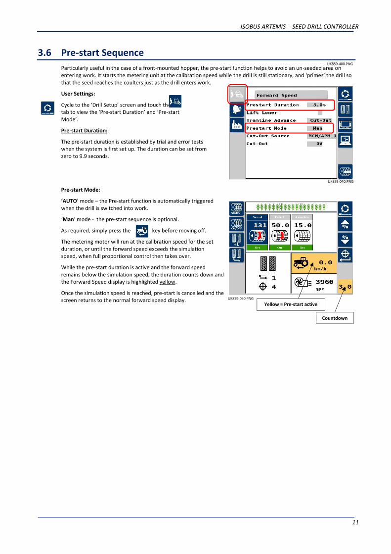
3.6 Pre-start SequenceParticularly useful in the case of a front-mounted hopper, the pre-start function helps to avoid an un-seeded area onentering work. It starts the metering unit at the calibration speed while the drill is still stationary, and ‘primes’ the drill sothat the seed reaches the coulters just as the drill enters work.
User Settings:
Cycle to the ‘Drill Setup’ screen and touch thetab to view the ‘Pre-start Duration’ and ‘Pre-startMode’.
Pre-start Duration:
The pre-start duration is established by trial and error testswhen the system is first set up. The duration can be set fromzero to 9.9 seconds.
Pre-start Mode:
‘AUTO’ mode – the Pre-start function is automatically triggeredwhen the drill is switched into work.
‘Man’ mode - the pre-start sequence is optional.
As required, simply press the key before moving off.
The metering motor will run at the calibration speed for the setduration, or until the forward speed exceeds the simulationspeed, when full proportional control then takes over.
While the pre-start duration is active and the forward speedremains below the simulation speed, the duration counts down andthe Forward Speed display is highlighted yellow.
Once the simulation speed is reached, pre-start is cancelled and thescreen returns to the normal forward speed display. UK859-050.PNG
Yellow = Pre-start active
Countdown
UK859-040.PNG
UK859-400.PNG

ISOBUS ARTEMIS - SEED DRILL CONTROLLER
12
3.7 TramliningThe main screen shows the current status of tramlining e.g.
Rhythm: Symmetrical Asymmetrical-left Asymmetrical-right
The target no. of bouts can be selected up to 99, with symmetrical, asymmetrical-left or asymmetrical-right rhythmselectable. A number of special asymmetric rhythms can also be selected to suit the following drill/sprayer widthcombinations.
The special tramline sequences (‘L’ – Left, ‘R’ – Right) are as follows:
Bout 8-pass 10-pass 10-pass (2) 14-pass 16-pass 18-pass 22-pass
1
2 R R L
3 L R L
4 L L L
5 L R
6 R
7 R L R R
8 R L
9 R L L
10
11 R
12 L R R
13
14 R
15
16 L
17
18
19 L
20
21
22
3.7.1 Advancing the Bout NumberOn starting up the instrument the tramline sequence alwaysstarts at ‘1’.
If entering work on a bout other than bout 1 of the tramlinesequence, then you can press the key to select thecorrect, current bout number.
Output Status (On)
Current Bout
Target No of Bouts

ISOBUS ARTEMIS - SEED DRILL CONTROLLER
13
3.7.2 Holding the Bout NumberIf it is necessary to take the drill out of work other than the normal headland turn, or depending on the drill setup - lift amarker to negotiate a field feature, the bout number will still automatically increment by 1.
You can however, press the key to hold the currentbout number (e.g. to prevent the bout no. advancing).
The icon indicates that the bout no. is held.
Press the key again to resume normal bout advance.
3.7.3 Setting the Tramline Rhythm
Cycle to the ‘Drill Setup’ screen and touch the tab toview/edit the ‘Target Bout’ and ‘Mode’ (rhythm) settings.
3.8 Forward Speed DisplayThe drilling rate is metric units only i.e. km/hr.
The forward speed signal is sourced from either,
RDS Satspeed 2 (converts a GPS NMEA VTG message to a radar-compatible speed pulse).
Radar Sensor
3.8.1 Forward Speed AlarmIf while the drill is switched into work and the indicated forward speed is below 0.2 km/hr, the display will flashcontinuously and the metering units are stopped.
This is intended to alert the operator in the event that the forward speed signal input has been lost for whatever reason.In this event however, you can activate a simulated forward speed so that you are able to continue drilling.
Tramline Number -normal advance mode
Tramline Numberheld
UK859-060.PNG

ISOBUS ARTEMIS - SEED DRILL CONTROLLER
14
3.8.2 Simulated Forward SpeedWhen the forward speed is simulated, the “Sim” icon appears on the display. Speedsimulation is activated either,
(i) Automatically during product calibration (in order to dispense product while the drill isstationary).
(ii) Manually in the event of losing the forward speed signal input (in order to continuedrilling). Remember though that your actual forward speed should match the simulatedspeed as close as possible, otherwise the drilling rate will not be correct. Drive fasterthan the simulated speed and you will under-apply, and vice-versa.
NOTE: The Pre-start mode also uses the simulated speed setting. Pre-start will be de-activatedwhen the actual forward speed exceeds the simulated speed.
The simulated speed is set and manually activated via the “Drill Setup” menu as follows,
User Settings:Cycle to the ‘Drill Setup’ screen and touch the tab, then select “Forward Speed”.
Set Simulated Speed:Go to “Simulated Speed”. The factory default simulated forward speed is 10 km/hr, however this can be changed tomatch your typical forward speed for drilling.
Start / Stop simulated Speed:Go to “Simulated Speed Status” and check the tickbox to enable.
NOTE: Speed simulation can only be activated when the drill is switched out of work.
UK859-070.PNG UK859-080.PNG

ISOBUS ARTEMIS - SEED DRILL CONTROLLER
15
3.9 Fan Speed DisplayThe Artemis can monitor and display the speed of either 1 or 2 fans depending on the drill configuration. If monitoringtwo fans, the display will alternate every 6 seconds between fan “1” and fan “2”.
3.9.1 Set Fan Speed AlarmsThere are both low speed and high speed programmable alarms.The low and high alarm speed thresholds can be set via the “DrillSetup” menu as follows,
Cycle to the ‘Drill Setup’ screen and touch the tab toview/edit the ‘Fan Low Limit’ and ‘Fan Hi Limit’ settings.
3.10 Hopper Level AlarmsHopper level alarms will alert the operator when the product isrunning low and/or has nearly run out. Depending on the drillconfiguration, for each hopper there is either,
(i) a single low-level sensor.
(ii) Both a low-level sensor and an upper “Pre-Level” level sensor.The additional “pre-level” sensor is positioned higher up in thehopper to provide the operator a more advanced warning. Thiscan avoid a possible disruption to drilling a long bout orunnecessary delay in replenishment.
To view the level sensor configuration applicable to eachmetering unit, cycle to the ‘Drill Setup’ screen and touch thetab.
Check the relevant tickbox to enable a sensor.
3.11 TotalsThe total Area and Weight of each product accumulates to the previously selected memory register, “Total 1”, “Total 2”or “Total 3” as shown.
The total is the total since last reset.
To reset any of the total registers, first select it and touch
You must then touch again to zero.
The Grand Total memory register cannot be reset.
UK859-120.PNG
UK859-130.PNG
UK859-020.PNG

ISOBUS ARTEMIS - SEED DRILL CONTROLLER
16
4. Blockage Monitoring (optional)Blockage monitoring is an optional feature. When enabled, this screen page appears after the ‘Totals’ screen page.
In the instance of a dual-product setup, select,
to view the sensor status for seed,
to view the sensor status for fertiliser.
The sensors are identified by the row number being monitored.
NOTE: On a dual-metering setup (e.g. Seed Left / Seed Right), when achannel is switched off, the sensor indicators will turn red, but therewill not be an alarm.
4.1 Blockage sensor status and alarmsNOTE: Lifting the drill out of work cancels all alarms.
Indication Status
GREEN The sensor is operating normally. The required seed flow is detected through thesensor.
RED Sensor blocked, either at the coulter or at the distribution head. The alarm message“Seed Sensor [xx] Row [xx] Blocked” or “Fert Sensor [xx] Row [xx] Blocked” willappear.Remove the blockage.Note: The Sensor No. relates to its position on the distribution head. The Row No. thatthe sensor is monitoring may not necessarily be the same as the Sensor No.
ORANGE (FLASHING) The sensor is detected on the CAN bus, however there is a break in communicationwith an adjacent sensor.The alarm message “Seed Communication Error” or “Fert Communication Error” willappear.Check the sensor connectors.
BLACK A sensor is not being detected on the CANbus, and is breaking communication withthe adjacent sensors.The alarm message “Seed Communication Error” or “Fert Communication Error” willappearCheck the sensor connectors, otherwise the sensor may be faulty and need to bereplaced.Note: A replacement sensor must be configured with the same ID No.
UK859-230.PNG

ISOBUS ARTEMIS - SEED DRILL CONTROLLER
17
4.2 Blockage sensor alarm overrideWhen a blockage occurs, after a pre-defined delay time, the alarm screen appears. You can choose to either,
(i) press to temporarily cancel the alarm. Until the blockage is cleared, the alarm will re-activate after 30 seconds.
(ii) press to ignore the alarm. The sensor icon changes to . Press to revert to the normal alarm function.
4.3 Sensor CalibrationIt is recommended to calibrate the sensors at the start of each drilling day. Start drilling and make sure everything is upto full speed and at normal operating condition.
Cycle to the Seed Sensor screen page. If all sensor indicators are showing green, then simply press toautomatically calibrate all the sensors.
Once calibrated, the sensitivity of the sensors is adjusted automatically for varying forward speed / application, e.g forVariable Rate Treatment from a plan.
UK859-260.PNG UK859-250.PNG

ISOBUS ARTEMIS - SEED DRILL CONTROLLER
18
5. Product CalibrationThere are two ways of running the calibration test,
from the head unit.
via the relevant priming switch on on the drill.
5.1 Running the test from the Cab1. From the main drilling screen, set the target rate for the channel(s) to be calibrated.
2. Setup the drill in the usual way for a bucket test on the appropriate metering unit.
3. Cycle to the ‘Drill Setup’ screen.
The screen displays the channel configuration as shown on themain operating screen. If multiple channels are configured, thecalibration routine must be repeated for each channel includinglinked channels ( ).
4. Select the channel to calibrate, then press .
5. Press or , (yourpreference) and enter the weight thatyou wish to meter out for the buckettest.
6. Press .
The metering unit will then operate (based on the simulationspeed) to dispense the programmed amount of product, thenstops.
NOTE: At any time you can touch to curtail the test.
UK859-160.PNG
UK859-175.PNG
UK859-180.PNG

ISOBUS ARTEMIS - SEED DRILL CONTROLLER
19
The instrument then displays a weight figure basedon the existing, programmed product calibrationfactor.
NOTE: In the case of a single motor / dual metering configuration( ) the product collected, weighed andprogrammed is that from BOTH metering units.
So in this case, before going to step 7, press and repeatsteps 5 and 6 for the second metering unit, then total bothweights.
7. Weigh the contents of the container. Press orand enter the weight THAT WAS DISPENSED
8. Press .
The new calibration factor (kg/rev),% error and the maximum forwardspeed that is permissible based onthe application rate set for thechannel.
9. Press to return to the “DrillSetup” screen.
5.2 Running the test using the Priming Switch1. From the main drilling screen, first set the target rate for the channel(s) to be calibrated.
2. Setup the drill in the usual way for a bucket test on the appropriate metering unit.
3. Press the priming switch to meter out the desired amount ofproduct.
NOTE: Depending on your particular drill configuration, the primingswitch(es) will be setup for either momentary or latching operation.
If set to latching, then press and release the switch to start metering,then press and release again to stop.
If set to momentary, then press and hold the switch to start metering,and release to stop.
The displays switches automatically to the calibration screen oncethe priming switch is pressed.
When the metering unit is stopped, the instrument then displays aweight figure based on the existing programmed product calibrationfactor.
NOTE: In the case of a single motor / dual metering configuration( ) the product collected, weighed andprogrammed is that from BOTH metering units.
So at this point, press and repeat steps 2 and 3 for thesecond metering unit, and total the dispensed weights.
4. Weigh the contents of the container. Press or ,(your preference) and enter the weight THAT WAS DISPENSED.
UK859-190.PNG
UK859-200.PNG
UK859-180.PNG
UK859-190.PNG

ISOBUS ARTEMIS - SEED DRILL CONTROLLER
20
5. Press .The new calibration factor (kg/rev), % error and the maximumforward speed that is permissible based on the application rateset for the channel.
6. Press to return to the main operating screen.
5.3 Calibrating systems with ‘Accord’ type metering mechanisms.When changing from a low rate to a high rate i.e. 3kg/ha to 100kg/ha
For each channel,
1. Move the metering slide to a position for the higher rate.
2. Perform the calibration test and enter the weight dispensed (as in 5.1 / 5.2).
3. The error will be considerable, but press to accept the error and continue.
4. From the main drilling screen, set the required target rate for the channel.
5. Perform the product calibration routine again.
6. The error this time will be marginal.
7. Press to accept the error, and begin drilling.
When changing from a high rate to a low rate i.e. 100kg/ha to 3kg/ha :
For each channel,
1. Move the metering slide to a position for the lower rate.
2. Perform the calibration test and enter the weight dispensed (as in 5.1 / 5.2).
NOTE: If using the priming switch simply dispense a small amount of product and enter the weight.
3. The error will be considerable, but press to accept the error and continue.
4. From the main drilling screen, set the required target rate for the channel.
5. Perform the product calibration routine again, this time dispensing a suitable amount of product.
6. The error this time will be marginal.
7. Press to accept the error, and begin drilling.
UK859-200.PNG

ISOBUS ARTEMIS - SEED DRILL CONTROLLER
21
6. Alarm CodesNo. Code Screen Reason Check?
1 N/A High forward speed
Forward speed exceedsthe maximumcalculated anddisplayed on the RATEscreen
Target application rate is asrequired
Calibration factor is realistic
Adjust metering unit and recalibratewhich will increase kg/rev factorand therefore increase maximumachievable forward speed
2 L.1 Low fan speed
Fan speed below thelow alarm valueprogrammed
Fan is actually operating
Sensor & target functioning andcorrect
PPR value programmed correctly
3 L.2 High fan speed
Fan speed is above thehigh alarm valueprogrammed
Sensor & target functioning andcorrect
PPR value programmed correctly
4 L.3.1 Low hopper level alarm
Channel with low levelhighlighted
Level is actually low
Sensor is functioning correctly
Wiring between sensor andconnection box is correct
Wiring between connection box andCAN module is correct
5 L.3.2
Pre-Level hopper alarm
Channel with low prelevel highlighted
Level is actually low
Sensor is functioning correctly
Wiring between sensor andconnection box is correct
Wiring between connection box andCAN module is correct
11 M.3.1
Motor speed signalfrom motor not beingreceived
Motor being operatedand pulses receivedfrom shaft confirmationsensors but no motorspeed signal
Signs of mechanical damage toencoder or cabling on motor
3way connector between motor andharness is correct
Wiring between 3way connector andmodule connector is correct
12 M.1
MCM or APM is offline’ Check wiring between 6wayconnector and module connector onMCM harness

ISOBUS ARTEMIS - SEED DRILL CONTROLLER
22
No. Code Screen Reason Check?
13 M.1.2
Module overloadshutdownMotor currentrequirement exceeded,so the module isshutdown and motoroperation is inhibited
The Motor is stalled.
Excessive drag on the meteringunit, requiring motor high current.
14 M.1.3
Motor moduletemperature shutdownModule temperaturehas exceeded the valueprogrammed
The Motor speed is very low.
Excessive load applied to motorwhich for a prolonged time,causing the module hightemperature and shutdown.
Check metering unit for damage /obstruction.
Re-calibrate to get motor turningfaster.
15 M.2.L Motor speed low
Error between actualmotor speed and targetmotor speed is greaterthan 10%
Target motor speed to high
Erratic forward speed signal
Erratic loading on motor viametering unit
16 M.2.H Motor speed high
Error between actualmotor speed and targetmotor speed is greaterthan 10%
Target motor speed to high
Erratic forward speed signal
Erratic loading on motor viametering unit
17 M.3 Metering unit is notgoing around
Is metering unit rotating whenmotor rotates
Sensor & target functioning andcorrect
PPR value programmed correctlyWiring between sensor andconnection box is correct
Wiring between connection box andCAN module is correct
18 - - -
19 H.1 Tramline module is‘offline’
Check module has got power frommain battery power cable
Check wiring between 4wayconnector and module connector onHBM harness

ISOBUS ARTEMIS - SEED DRILL CONTROLLER
23
No. Code Screen Reason Check?
20 G.1 GPS signal lost. Check connections to GPS antenna.
Check GPS coverage for Area
21 B.1 Bridge Module is‘offline’
22 B.M.1 Blockage monitoringECU is ‘offline’
Check power supply to blockageECU
Check wiring between powerharness and blockage ECU
Check LEDs are lit and flashing onblockage ECU
23 B.M.2 Wrong number ofblockage sensors isdetected
The correct number of sensors isprogrammed in blockage ECUsetup
All sensors are wired correctly andconnected
24 B.M.3 Blocked sensor/row Row or pipe is actually blocked
25 B.M.4 Communication breakbetween blockagesensors
Wiring between blockage sensors
The correct number of sensors isprogrammed
26 E.H.1 Electro hydraulicmodule offline
Check wiring between 4waysuperseal and connection to themain loom.

ISOBUS ARTEMIS - SEED DRILL CONTROLLER
24
Issue Ref. Date Notes
A 14.10.16 1st Draft : Derived from UK805200
B 1.3.17 2nd draft : re-formatted
B 23.3.17 3nd draft : (Section 1 added note)

ISOBUS ARTEMIS - SEED DRILL CONTROLLER
2


www.rdstec.com
ENGLISH S/DC/500-10-859Doc. Ref: UK859-C.DOCXDoc. Revision: C : 23.3.17Software Rev: IS105002rev43
RDS Technology LtdCirencester Road, Minchinhampton,Stroud, Gloucestershire, GL6 9BH, UKPhone: +44 (0)1453 733300Fax: +44 (0)1453 733311 (General)
+44 (0)1453 733322 (Engineering)+44 (0)1453 733313 (Repair)
Email: [email protected] policy is one of continuous improvement and theinformation in this document is subject to change withoutnotice. Check that the software reference matches thatdisplayed by the instrument.Please visit our website for technical support or otherproduct information. Replacement user manuals areavailable on request.© Copyright RDS Technology Ltd 2017
![Index [juta.co.za] · Web viewCounsel is required to be properly dressed. If not properly dressed they run the risk of not being “seen” by the presiding judge. Proper dress for](https://img.pdfslide.net/doc/110x75/61083f4240ba394704510ce3/index-jutacoza-web-view-counsel-is-required-to-be-properly-dressed-if-not-properly.jpg)