Embed Size (px)
Citation preview
GEO-CHIANGMAI 2008 An International onference on Geotechnical Engineering Focusing on New Developments in Soil & Rock Engineering, Engineering Geology & Environmental Geotechnique December 10-12, 2008 at Centara Chiangmai, Thailand
Seepage Analyses and Monitoring of Khlong Tha Dan Dam Warakorn Mairaing Chinoros Thongtamachat Nattapol Chisiwamongcol
ABSTRACT
The Khun Dan Prakarnchon Dam, the largest RCC gravity dam in Thailand, has been completed since 2005. During the construction, the revised seepage analysis was performed according to the field data. On the 1st and 2nd year of impounding, the pressures under the dam foundation were carefully monitored. For the 1st impounding, the piezometric heads were activated when the water level has been raised above 25 m above the dam foundation level. The discharges of foundation and dam body drains which were measured by 80 V-Notch weirs in the dam galleries show 50% decreasing from the 1st to 2nd year mainly because of self-healing in micro-cracks in the dam body. Uplift pressure on the foundation is lower than the prediction and the factor of safety against sliding and overturning can be checked during the operation.
INTRODUCTION
Khlong Tha Dan or Khun Dan Prakranchol Dam, one of the King’s initiated projects, is considered to be the largest Roller Compacted Concrete (RCC) Dam in Thailand. The dam is 93 meters high, 2600 meters long with the dam volume of 5.4 MCM of concrete and reservoir volume of 224 MCM. It is situated at about 20 kilometers upstream from the city of Nakorn Nayok, one of the famous tourism area. The dam is founded on the complex volcanic rocks of rhyolite, andesite, rhyolitic and andesitic tuffs, agglomerates and volcanic breccia. The permeabilities of the rock foundations are heterogeneous so a deep upstream grouting curtain and two drainage curtains are designed to control seepage and uplift pressure in the dam foundation. Seepage analysis during construction was reviewed according to the actual field pumping tests. And seepage behaviors during the first two years of impounding are monitored by 106 piezometers, 80 V-notch weirs and Observation wells. The actual monitoring data and previous seepage analyses are compared and verified to reflect the suitable modelling for future design. The actual seepage behavior can also ensure the safety evaluation of the dam at the initial stage of reservoir impounding.
PROJECT FEATURES
General Tha Dan Dam is a storage dam on the upper Nakorn Nayok River at the foot of Khao Yai mountain range one of Thai’s famous national park. About 93 percent of the average annual flow of 337 million cubic meters occurs during only 5 months from June to October causing flood on the downstream area almost every year. Since the catchment area is on the steep slope connected to the rather flat flood plain on the downstream thus the flash flood usually cause damage to the agriculture and residential area. On 1993, King Bhumipol initiated this project to Royal Irrigation Department(RID.) to investigate the possibility for construction the dam. The purposes of the dam are for irrigation, flood protection, domestic and industrial water supply and leaching of acid sulphate soil. After the extensive study, RID.
GEO-CHIANGMAI 2008 An International onference on Geotechnical Engineering Focusing on New Developments in Soil & Rock Engineering, Engineering Geology & Environmental Geotechnique December 10-12, 2008 at Centara Chiangmai, Thailand
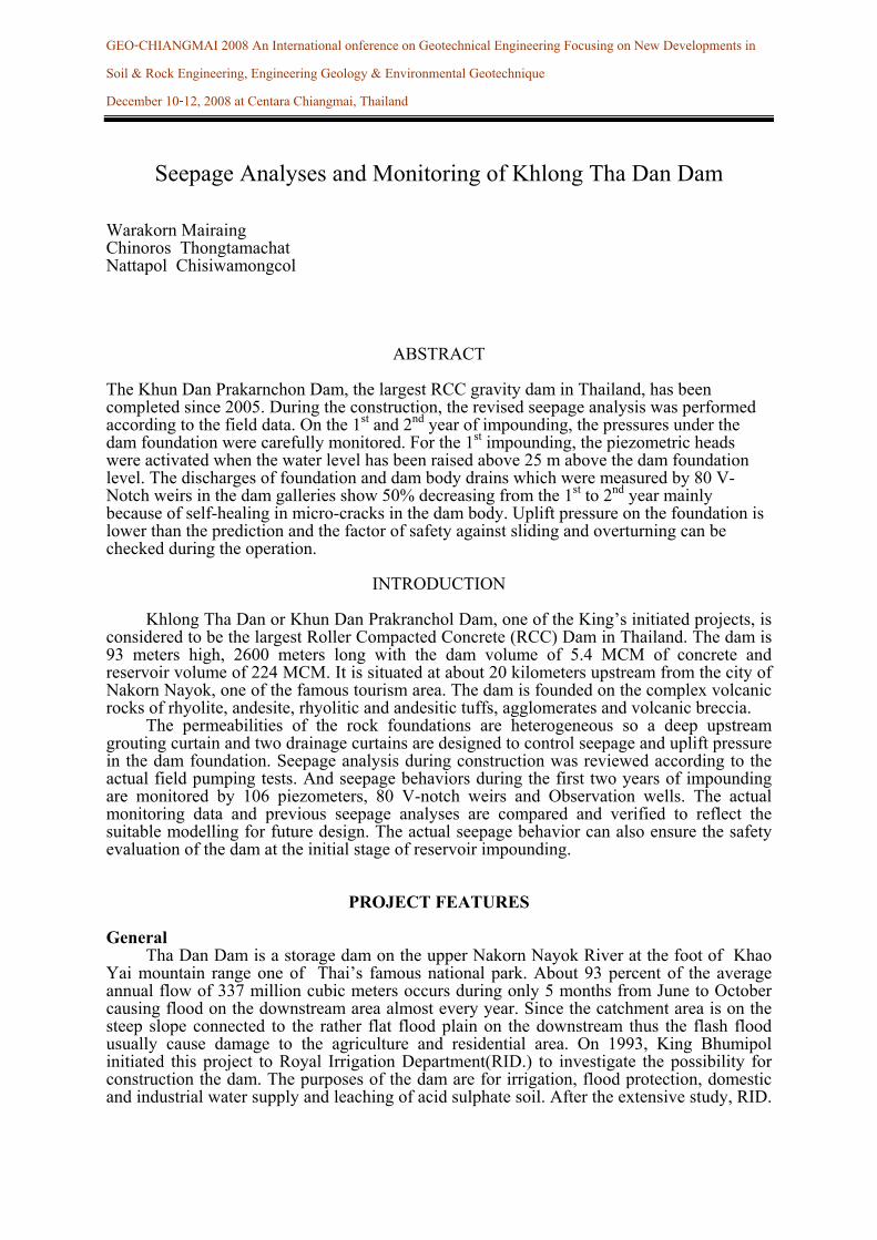
decide to construct the first Roller Compacted Concrete Dam mainly due to the lack of soil and rock for the conventional embankment dam. At the present, this dam is considered as the largest RCC dam in Thailand. The project lay-out is shown on the Figure 1.
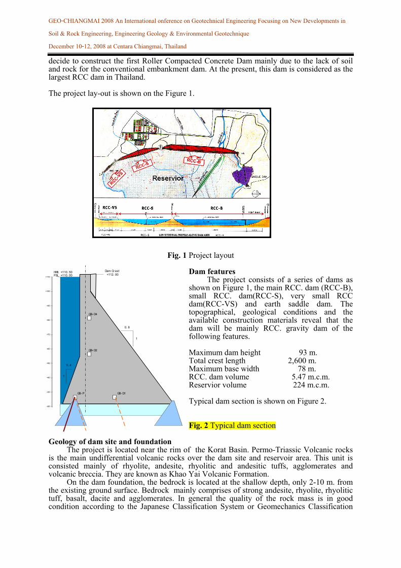
Fig. 1 Project layout Dam features The project consists of a series of dams as shown on Figure 1, the main RCC. dam (RCC-B), small RCC. dam(RCC-S), very small RCC dam(RCC-VS) and earth saddle dam. The topographical, geological conditions and the available construction materials reveal that the dam will be mainly RCC. gravity dam of the following features. Maximum dam height 93 m. Total crest length 2,600 m. Maximum base width 78 m. RCC. dam volume 5.47 m.c.m. Reservior volume 224 m.c.m. Typical dam section is shown on Figure 2. Fig. 2 Typical dam section
Geology of dam site and foundation The project is located near the rim of the Korat Basin. Permo-Triassic Volcanic rocks is the main undifferential volcanic rocks over the dam site and reservoir area. This unit is consisted mainly of rhyolite, andesite, rhyolitic and andesitic tuffs, agglomerates and volcanic breccia. They are known as Khao Yai Volcanic Formation. On the dam foundation, the bedrock is located at the shallow depth, only 2-10 m. from the existing ground surface. Bedrock mainly comprises of strong andesite, rhyolite, rhyolitic tuff, basalt, dacite and agglomerates. In general the quality of the rock mass is in good condition according to the Japanese Classification System or Geomechanics Classification
0. 8
1
0. 4
1
Dam Cr est +112. 00
GB- D4
GB- D2
GB- P GB- D1
FSL +110. 00+110
+100
+90
+80
+70
+60
+50
+40
+30
+20
HWL +110. 50
GEO-CHIANGMAI 2008 An International onference on Geotechnical Engineering Focusing on New Developments in Soil & Rock Engineering, Engineering Geology & Environmental Geotechnique December 10-12, 2008 at Centara Chiangmai, Thailand
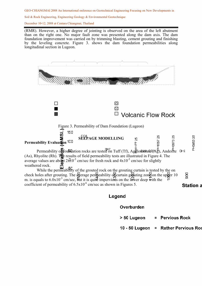
(RMR). However, a higher degree of jointing is observed on the area of the left abutment than on the right one. No major fault zone was presented along the dam axis. The dam foundation improvement was carried on by trimming blasting, cement grouting and finishing by the leveling concrete. Figure 3. shows the dam foundation permeabilities along longitudinal section in Lugeon.
Figure 3. Permeability of Dam Foundation (Lugeon)
SEEPAGE MODELLING
Permeability Evaluation
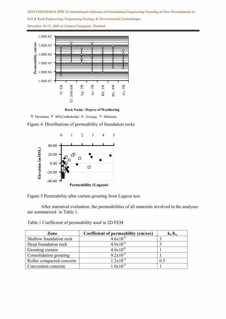
Permeability of foundation rocks are tested on Tuff (Tf), Agglomerate (Ag), Andesite (As), Rhyolite (Rh). The results of field permeability tests are illustrated in Figure 4. The average values are about 2x10⁻⁵ cm/sec for fresh rock and 4x10⁻⁵ cm/sec for slightly weathered rock.
While the permeability of the grouted rock on the grouting curtain is tested by the on check holes after grouting. The average permeability of curtain grouting zone on the upper 10 m. is equals to 6.0x10⁻⁵ cm/sec, but it is quite impervious on the lower deep with the coefficient of permeability of 6.5x10⁻⁶ cm/sec as shown in Figures 5.
GEO-CHIANGMAI 2008 An International onference on Geotechnical Engineering Focusing on New Developments in Soil & Rock Engineering, Engineering Geology & Environmental Geotechnique December 10-12, 2008 at Centara Chiangmai, Thailand
1.00E-07
1.00E-06
1.00E-05
1.00E-04
1.00E-03
1.00E-02
Tf : F
R
Tf : H
W-SW
Ag : F
R
As : F
R
Rh : F
R
Rh : S
W
As : F
R
Rock Name : Degree of Weathering
Perm
eabil
ity, c
m/sec
Maximum 90%Confindential Average Minimum
Figure 4. Distributions of permeability of foundation rocks
-40.00
-20.00
0.00
20.00
40.00
0 1 2 3 4 5
Permeability (Lugeon)
Elev
ation
(mM
SL)
Figure 5 Permeability after curtain grouting from Lugeon test. After statistical evaluation, the permeabilities of all materials involved in the analyses are summarized in Table 1. Table 1 Coefficient of permeability used in 2D FEM
Zone Coefficient of permeability (cm/sec) ky/kx Shallow foundation rock 4.6x10⁻⁴ 3 Deep foundation rock 4.9x10⁻⁶ 3 Grouting curtain 4.6x10⁻⁶ 1 Consolidation grouting 9.2x10⁻⁶ 1 Roller compacted concrete 1.2x10⁻⁴ 0.5 Convention concrete 1.0x10⁻⁶ 1
GEO-CHIANGMAI 2008 An International onference on Geotechnical Engineering Focusing on New Developments in Soil & Rock Engineering, Engineering Geology & Environmental Geotechnique December 10-12, 2008 at Centara Chiangmai, Thailand
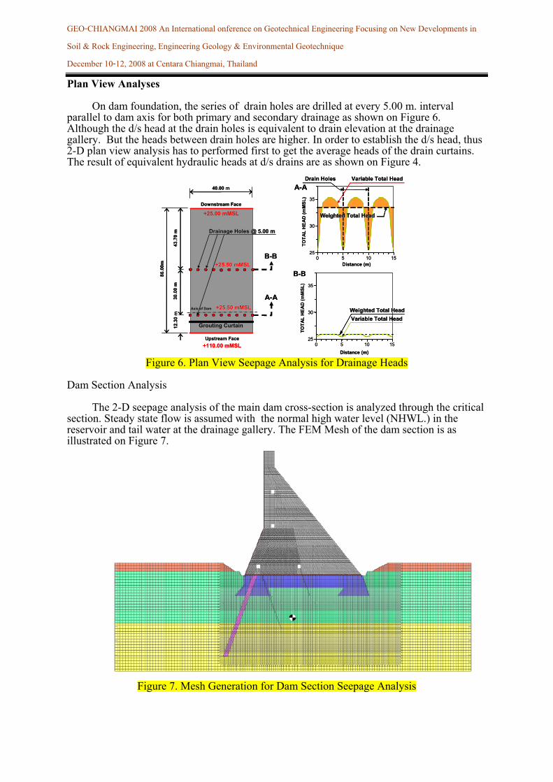
Plan View Analyses On dam foundation, the series of drain holes are drilled at every 5.00 m. interval parallel to dam axis for both primary and secondary drainage as shown on Figure 6. Although the d/s head at the drain holes is equivalent to drain elevation at the drainage gallery. But the heads between drain holes are higher. In order to establish the d/s head, thus 2-D plan view analysis has to performed first to get the average heads of the drain curtains. The result of equivalent hydraulic heads at d/s drains are as shown on Figure 4.
Figure 6. Plan View Seepage Analysis for Drainage Heads
Dam Section Analysis The 2-D seepage analysis of the main dam cross-section is analyzed through the critical section. Steady state flow is assumed with the normal high water level (NHWL.) in the reservoir and tail water at the drainage gallery. The FEM Mesh of the dam section is as illustrated on Figure 7.
Figure 7. Mesh Generation for Dam Section Seepage Analysis
25
30
35
0 5 10 15Distance (m)
TOTA
L H
EAD
(mM
SL)
A-A
Drainage Holes Drainage Holes @@ 5.005.00 mm
Axis of Dam
A-A
43.7
0m
30.0
0m
12.3
0m
86.0
0m
++25.50 25.50 mMSmMSLL
Grouting Curtain
Drain Holes
0 5 10 15Distance (m)
B-B
Variable Total HeadWeighted Total Weighted Total HHeadead
Variable Total Head
Weighted Total Weighted Total HHeadead
25
30
35
TOTA
L H
EAD
(mM
SL)
++25.50 25.50 mMSmMSLL
+25.00 mMSLDownstream Face
Upstream Face+110.00 mMSL
40.00 m
B-B 25
30
35
0 5 10 15Distance (m)
TOTA
L H
EAD
(mM
SL)
A-A
Drainage Holes Drainage Holes @@ 5.005.00 mm
Axis of Dam
A-A
43.7
0m
30.0
0m
12.3
0m
86.0
0m
++25.50 25.50 mMSmMSLL
Grouting Curtain
Drain Holes
0 5 10 15Distance (m)
B-B
Variable Total HeadWeighted Total Weighted Total HHeadeadWeighted Total Weighted Total HHeadead
Variable Total Head
Weighted Total Weighted Total HHeadeadWeighted Total Weighted Total HHeadead
25
30
35
TOTA
L H
EAD
(mM
SL)
++25.50 25.50 mMSmMSLL
+25.00 mMSLDownstream Face
Upstream Face+110.00 mMSL
40.00 m
B-B
GEO-CHIANGMAI 2008 An International onference on Geotechnical Engineering Focusing on New Developments in Soil & Rock Engineering, Engineering Geology & Environmental Geotechnique December 10-12, 2008 at Centara Chiangmai, Thailand
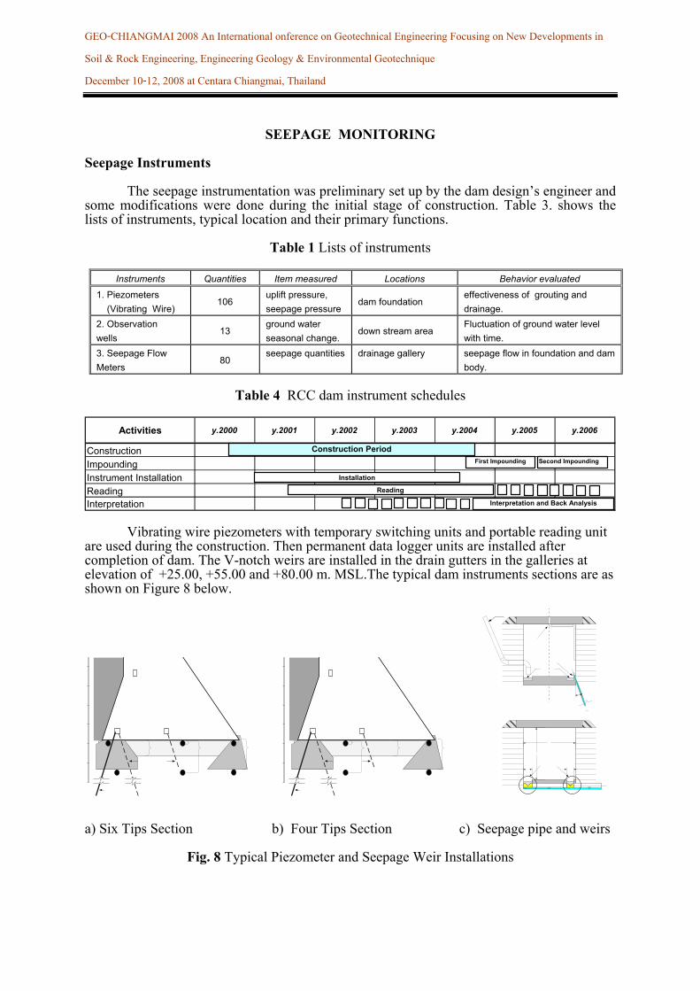
SEEPAGE MONITORING Seepage Instruments The seepage instrumentation was preliminary set up by the dam design’s engineer and some modifications were done during the initial stage of construction. Table 3. shows the lists of instruments, typical location and their primary functions.
Table 1 Lists of instruments
Instruments Quantities Item measured Locations Behavior evaluated
1. Piezometers (Vibrating Wire)
106 uplift pressure, seepage pressure
dam foundation effectiveness of grouting and drainage.
2. Observation wells
13 ground water seasonal change.
down stream area Fluctuation of ground water level with time.
3. Seepage Flow Meters
80 seepage quantities drainage gallery seepage flow in foundation and dam
body.
Table 4 RCC dam instrument schedules
Activities y.2000 y.2001 y.2002 y.2003 y.2004 y.2005 y.2006
ConstructionImpoundingInstrument InstallationReadingInterpretation
Construction PeriodFirst Impounding Second Impounding
Installation
Reading
Interpretation and Back Analysis Vibrating wire piezometers with temporary switching units and portable reading unit are used during the construction. Then permanent data logger units are installed after completion of dam. The V-notch weirs are installed in the drain gutters in the galleries at elevation of +25.00, +55.00 and +80.00 m. MSL.The typical dam instruments sections are as shown on Figure 8 below.
a) Six Tips Section b) Four Tips Section c) Seepage pipe and weirs
Fig. 8 Typical Piezometer and Seepage Weir Installations
GEO-CHIANGMAI 2008 An International onference on Geotechnical Engineering Focusing on New Developments in Soil & Rock Engineering, Engineering Geology & Environmental Geotechnique December 10-12, 2008 at Centara Chiangmai, Thailand
RESULTS
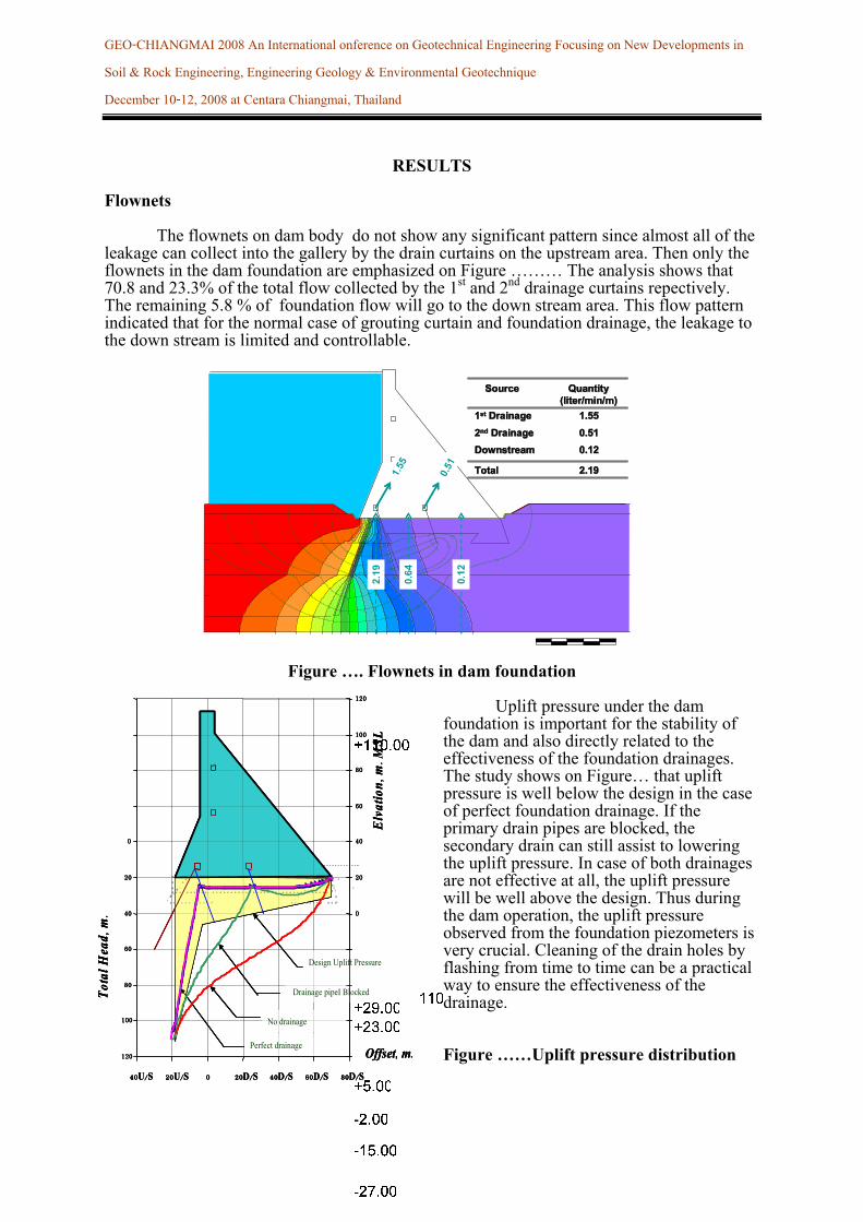
Flownets The flownets on dam body do not show any significant pattern since almost all of the leakage can collect into the gallery by the drain curtains on the upstream area. Then only the flownets in the dam foundation are emphasized on Figure ……… The analysis shows that 70.8 and 23.3% of the total flow collected by the 1st and 2nd drainage curtains repectively. The remaining 5.8 % of foundation flow will go to the down stream area. This flow pattern indicated that for the normal case of grouting curtain and foundation drainage, the leakage to the down stream is limited and controllable.
Figure …. Flownets in dam foundation
Uplift pressure under the dam foundation is important for the stability of the dam and also directly related to the effectiveness of the foundation drainages. The study shows on Figure… that uplift pressure is well below the design in the case of perfect foundation drainage. If the primary drain pipes are blocked, the secondary drain can still assist to lowering the uplift pressure. In case of both drainages are not effective at all, the uplift pressure will be well above the design. Thus during the dam operation, the uplift pressure observed from the foundation piezometers is very crucial. Cleaning of the drain holes by flashing from time to time can be a practical way to ensure the effectiveness of the drainage. Figure ……Uplift pressure distribution
2.19
0.64
0.12
1.55
0.51
11stst DrainageDrainage
SourceSource QuantityQuantity((liter/min/mliter/min/m))
22ndnd DrainageDrainage
DownstreamDownstream
TotalTotal
1.551.55
0.510.51
0.120.12
2.192.19
2.19
0.64
0.12
1.55
0.51
11stst DrainageDrainage
SourceSource QuantityQuantity((liter/min/mliter/min/m))
22ndnd DrainageDrainage
DownstreamDownstream
TotalTotal
1.551.55
0.510.51
0.120.12
2.192.19
11stst DrainageDrainage
SourceSource QuantityQuantity((liter/min/mliter/min/m))
22ndnd DrainageDrainage
DownstreamDownstream
TotalTotal
1.551.55
0.510.51
0.120.12
2.192.19
Perfect drainage
No drainage
Drainage pipeI Blocked
Design Uplift Pressure
120
100
80
60
40
20
0
40U/S 20U/S 0 20D/S 40D/S 60D/S 80D/S
Offset, m.
Tota
l Hea
d,m. 0
20
40
60
80
100
120
Elv
atio
n,m.M
SL
Perfect drainage
No drainage
Drainage pipeI Blocked
Design Uplift Pressure
120
100
80
60
40
20
0
40U/S 20U/S 0 20D/S 40D/S 60D/S 80D/S
Offset, m.
Tota
l Hea
d,m. 0
20
40
60
80
100
120
Elv
atio
n,m.M
SL
Perfect drainage
No drainage
Drainage pipeI Blocked
Design Uplift Pressure
Perfect drainage
No drainage
Drainage pipeI Blocked
Design Uplift Pressure
120
100
80
60
40
20
0
40U/S 20U/S 0 20D/S 40D/S 60D/S 80D/S
Offset, m.
Tota
l Hea
d,m. 0
20
40
60
80
100
120
Elv
atio
n,m.M
SL
GEO-CHIANGMAI 2008 An International onference on Geotechnical Engineering Focusing on New Developments in Soil & Rock Engineering, Engineering Geology & Environmental Geotechnique December 10-12, 2008 at Centara Chiangmai, Thailand
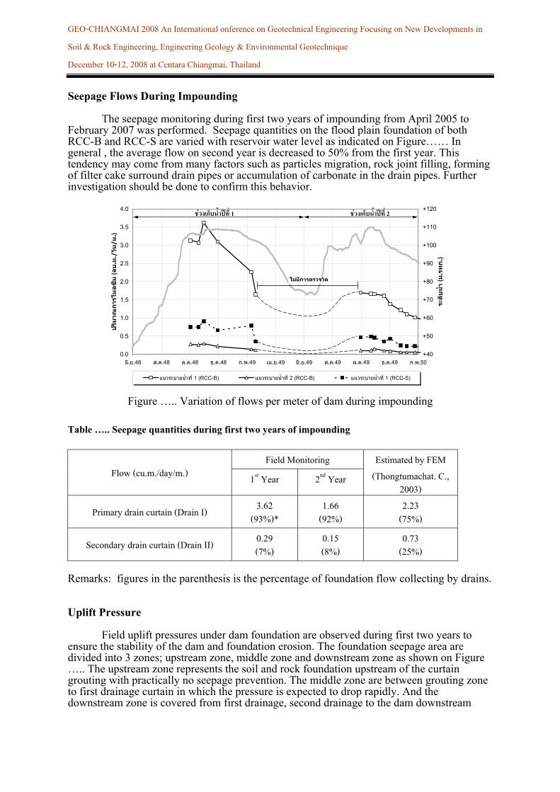
Seepage Flows During Impounding The seepage monitoring during first two years of impounding from April 2005 to February 2007 was performed. Seepage quantities on the flood plain foundation of both RCC-B and RCC-S are varied with reservoir water level as indicated on Figure…… In general , the average flow on second year is decreased to 50% from the first year. This tendency may come from many factors such as particles migration, rock joint filling, forming of filter cake surround drain pipes or accumulation of carbonate in the drain pipes. Further investigation should be done to confirm this behavior.
Figure ….. Variation of flows per meter of dam during impounding
Table ….. Seepage quantities during first two years of impounding
Field Monitoring Flow (cu.m./day/m.) 1st Year 2nd Year
Estimated by FEM (Thongtumachat. C.,
2003)
Primary drain curtain (Drain I) 3.62 (93%)*
1.66 (92%)
2.23 (75%)
Secondary drain curtain (Drain II) 0.29 (7%)
0.15 (8%)
0.73 (25%)
Remarks: figures in the parenthesis is the percentage of foundation flow collecting by drains. Uplift Pressure Field uplift pressures under dam foundation are observed during first two years to ensure the stability of the dam and foundation erosion. The foundation seepage area are divided into 3 zones; upstream zone, middle zone and downstream zone as shown on Figure ….. The upstream zone represents the soil and rock foundation upstream of the curtain grouting with practically no seepage prevention. The middle zone are between grouting zone to first drainage curtain in which the pressure is expected to drop rapidly. And the downstream zone is covered from first drainage, second drainage to the dam downstream
0.0
0.5
1.0
1.5
2.0
2.5
3.0
3.5
4.0
มิ.ย.48 ส.ค.48 ต.ค.48 ธ.ค.48 ก.พ.49 เม.ย.49 มิ.ย.49 ส.ค.49 ต.ค.49 ธ.ค.49 ก.พ.50
ปริมาณการไหลซึม
( ลบ
.ม./วัน
/ม.)
+40
+50
+60
+70
+80
+90
+100
+110
+120
ระดับน้ํา
( ม.รทก
.)
แนวระบายน้ําที่ 1 (RCC-B) แนวระบายน้ําที่ 2 (RCC-B) แนวระบายน้ําที่ 1 (RCC-S)
ชวงเกบ็น้ําปท่ี 1 ชวงเกบ็น้ําปท่ี 2
ไมมกีารตรวจวัด
GEO-CHIANGMAI 2008 An International onference on Geotechnical Engineering Focusing on New Developments in Soil & Rock Engineering, Engineering Geology & Environmental Geotechnique December 10-12, 2008 at Centara Chiangmai, Thailand
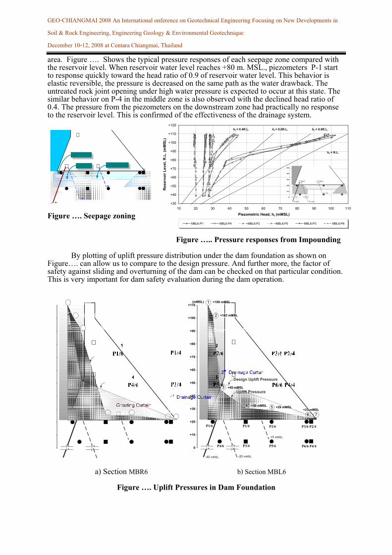
area. Figure …. Shows the typical pressure responses of each seepage zone compared with the reservoir level. When reservoir water level reaches +80 m. MSL., piezometers P-1 start to response quickly toward the head ratio of 0.9 of reservoir water level. This behavior is elastic reversible, the pressure is decreased on the same path as the water drawback. The untreated rock joint opening under high water pressure is expected to occur at this state. The similar behavior on P-4 in the middle zone is also observed with the declined head ratio of 0.4. The pressure from the piezometers on the downstream zone had practically no response to the reservoir level. This is confirmed of the effectiveness of the drainage system.
Figure …. Seepage zoning Figure ….. Pressure responses from Impounding By plotting of uplift pressure distribution under the dam foundation as shown on Figure…. can allow us to compare to the design pressure. And further more, the factor of safety against sliding and overturning of the dam can be checked on that particular condition. This is very important for dam safety evaluation during the dam operation.
+110
+100
+80
+70
+60
+50
+40
+30
+20
+90
(mMSL)
+10
0
21
P2/6P1/6
54
P5/6P4/6
-40 mMSL -20 mMSL
+5 mMSL
1
2
7
+109 mMSL
+103 mMSL
+23 mMSL
P3/6 P2/4P1/4
P6/6 P4/4P3/4
Design Uplift Pressure
Uplift Pressure+45 mMSL3
+30 mMSL4 5 +29 mMSL
6
a) Section MBR6 b) Section MBL6
Figure …. Uplift Pressures in Dam Foundation
+30
+40
+50
+60
+70
+80
+90
+100
+110
+120
10 20 30 40 50 60 70 80 90 100 110
Piezometric Head, ht (mMSL)
Res
ervo
ir Le
vel,
R.L
. (m
MSL
)
MBL6-P1 MBL6-P4 MBL6-P2 MBL6-P5 MBL6-P3 MBL6-P6
ht = R.L.
ht = 0.8R.L.ht = 0.6R.L.ht = 0.4R.L.
2 3
+50
+40
+30
+20
5 64
1
+10
0
-40 mMSL -20 mMSL
+5 mMSL
GB-D1GB-P
GEO-CHIANGMAI 2008 An International onference on Geotechnical Engineering Focusing on New Developments in Soil & Rock Engineering, Engineering Geology & Environmental Geotechnique December 10-12, 2008 at Centara Chiangmai, Thailand
CONCLUSIONS
1. The King’s initiated Khlong Tha Dan Dam is the first and largest RCC dam in Thailand
under construction. The dam is 93 meters high, 2600 meter long and required RCC volume of 5.47 MCM. The seepage analyses and field monitoring of the dam are essential for the design and dam safety evaluation during operation.
2. Seepage analysis by FEM can be useful tool to prediction the seepage behavior of the dam in the design stage. And revised analysis is repeated according to the most recent data obtained during construction. The average seepage through the foundation is 2.19 liter/min/m. and 70.8, 23.3, and 5.8 % flow to primary drain, secondary drain and downstream area of the dam respectively. Predicted uplift pressure is well lower than the design assumption.
3. The results from field monitoring show the flow quantities decreased to 50% on second impounding year comparing to the first year.
4. Observed uplift pressures are generally less than the design. The pressure on the upstream area responses to the reservoir level distinctively when the reservoir is at +80.00 m.MSL. On the area of zone 2 and 3 downstream of grouting curtain, the pressure is well controlled by the foundation drainage system.
5. Measuring of uplift pressures from piezometers can allow for continuous calculating the factor of safety against sliding and overturning of the dam during operation.
REFERENCES 1. RID. (1998) Design Note on Khlong Tha Dan Dam, prepared by Asdecon Cooperation, Team Consulting Engineer and Coyne et Bellier. 2. RID. (1998) Design Drawings for Khlong Tha Dan Dam, prepared by Asdecon Cooperation, Team Consulting Engineer and Coyne et Bellier. 3. RID. (2000)Shop Drawings for the Dam Instrumentation Work, prepared by CCVK. contractor joint venture for construction of Khlong Tha Dan Dam. 5. Mairaing W. (1995) Dam Instrumentation Manual, Kasetsart University (in Thai) 6. Mairaing W. (2006) Dam Instrumentation Manual 2nd Edition, Kasetsart University (in
Thai) 7. Mairaing W. (1998) Design of Embankment Dam, Library Nine Publishing (inThai) 8. RID. (2007), Final Report on Field Monitoring, Post Construction Analysis and RCC
Dam Technology Transfer for Khlong Tha Dan Dam, prepared by Geotechnical Engineering Research and Development Center, Kasetsart University, Bangkok.
9. RID.(1996), Feasibility Report for Khlong Tha Dan Dam, Main Report, prepared by Adecon, COT and TAE consultant joint ventures. (In Thai) 7. Hansen, K.D. and W.G. Reihardt (1991) Roller-Compacted Concrete Dams, McGraw-Hill, Inc., New York. 8 Mairaing W. (1999) Earth Dam Engineering. 2nd Edition, Library Nine Publishing Co.,
Bangkok. ( In Thai) 9 Thongtumachat C.,(2003) Seepage Analysis of Khlong Tha Dan Dam, Master’s Thesis,
Kasetsart University. 10 Chaisiwamongkol N.,(2008), Behaviors of Khun Dan Prakarnchon dam during
construction and initial impounding, Master’s Thesis, Kasetsart University. 11 Pantachang T.,(2005), 2548. Analyses of stress and deformation in Khlong Tha Dan Dam
foundation, Master’s Thesis, Kasetsart University. 12 Mairaing,W. and Felix Y.,(2000) Monitoring the Largest RCC Dam in Thailand: Khlong
Tha Dan Dam. Regional Symposium on Infrastructure Development in Civil Engineering, Tokyo Institute of Technology, Japan.