Embed Size (px)
Citation preview
SEER for Software User's Guide Page 1
SEER for Software ®
User’s Guide
Galorath Incorporated
www.galorath.com (310) 414-3222
Page 2 SEER for Software User’s Guide
SEER for Software™, the SEER® Software Estimation Model
Software Estimation, Planning, and Project Control
January 2014 Update.
Printed in the United States of America. The SEER for Software™ Documentation Team: MC, SA, KM. Copyright 2014 by Galorath Incorporated.
SEER® is a trademark of Galorath Incorporated.
No portion of this manual (except where explicitly stated) may be reproduced in any form without the express written permission of Galorath Incorporated.
This document contains material which has been extracted from the IFPUG Counting Practices Manual. It is reproduced in this document with permission of IFPUG.

SEER for Software User's Guide Page 3
Contents Contents.................................................................................................................................. 3 Introduction ............................................................................................................................ 4
Projects and Work Elements ................................................................................................5 Input and Output Windows ...................................................................................................5 Estimating with SEER for Software.......................................................................................6 Edition Features and Optional Add-ons ................................................................................7
SEER for Software Knowledge Bases ..................................................................................... 7 Platform Knowledge Bases...................................................................................................7 Application Knowledge Bases ............................................................................................10 Acquisition Method Knowledge Bases ...............................................................................14 Development Method Knowledge Bases ............................................................................17 Development Standard Knowledge Bases .........................................................................18 Component Type Knowledge Bases (COTS only) ................................................................21 Test Rigor Knowledge Bases (COTS only) ...........................................................................21 Class Knowledge Bases......................................................................................................21 Knowledge Base Allocations ..............................................................................................21 Opening and Reviewing Knowledge Base Files ..................................................................23 Creating a New Knowledge Base........................................................................................23
SEER for Software Parameters ............................................................................................. 24 Sizing Parameters ..............................................................................................................24 Technology and Environment Parameters ..........................................................................26 Other Parameters ...............................................................................................................36 Commercial Off-The-Shelf (COTS) Parameters ...................................................................44 SEER for Software Parameter Sensitivities ........................................................................49 Removing Requirements and System Integration from an Estimate..................................50
Sizing in SEER for Software .................................................................................................. 50 Source Lines of Code (Classic) ...........................................................................................50 Function Counting ..............................................................................................................52 Proxy Sizing ........................................................................................................................61
SEER for Software Outputs ................................................................................................... 62 Quick Estimate Outputs ......................................................................................................62 Labor Categories and Development Activities ....................................................................63
Exporting Data from SEER for Software ............................................................................... 65 Tools / Flexible Export ........................................................................................................65 Tools / Export Commands ..................................................................................................65 Tools / Export Report .........................................................................................................65 Linking to Microsoft Project................................................................................................65 Object Linking and Embedding (OLE) .................................................................................66
Using Edition Features ......................................................................................................... 66 Estimate by Comparison.....................................................................................................66 Microsoft Project Integration ..............................................................................................68 Project Monitor & Control ...................................................................................................69 Metrics Analysis & Benchmarking ......................................................................................71 ProjectMiner .......................................................................................................................72
Page 4 SEER for Software User’s Guide
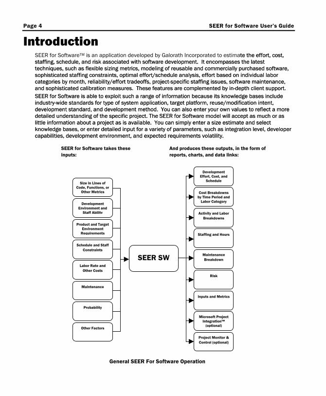
Introduction SEER for SoftwareTM is an application developed by Galorath Incorporated to estimate the effort, cost, staffing, schedule, and risk associated with software development. It encompasses the latest techniques, such as flexible sizing metrics, modeling of reusable and commercially purchased software, sophisticated staffing constraints, optimal effort/schedule analysis, effort based on individual labor categories by month, reliability/effort tradeoffs, project-specific staffing issues, software maintenance, and sophisticated calibration measures. These features are complemented by in-depth client support.
te the effort, cost, staffing, schedule, and risk associated with software development. It encompasses the latest techniques, such as flexible sizing metrics, modeling of reusable and commercially purchased software, sophisticated staffing constraints, optimal effort/schedule analysis, effort based on individual labor categories by month, reliability/effort tradeoffs, project-specific staffing issues, software maintenance, and sophisticated calibration measures. These features are complemented by in-depth client support. SEER for Software is able to exploit such a range of information because its knowledge bases include industry-wide standards for type of system application, target platform, reuse/modification intent, development standard, and development method. You can also enter your own values to reflect a more detailed understanding of the specific project. The SEER for Software model will accept as much or as little information about a project as is available. You can simply enter a size estimate and select knowledge bases, or enter detailed input for a variety of parameters, such as integration level, developer capabilities, development environment, and expected requirements volatility.
SEER for Software is able to exploit such a range of information because its knowledge bases include industry-wide standards for type of system application, target platform, reuse/modification intent, development standard, and development method. You can also enter your own values to reflect a more detailed understanding of the specific project. The SEER for Software model will accept as much or as little information about a project as is available. You can simply enter a size estimate and select knowledge bases, or enter detailed input for a variety of parameters, such as integration level, developer capabilities, development environment, and expected requirements volatility.
SEER for Software takes these inputs:
And produces these outputs, in the form of
Development Effort, Cost, and
Size in Lines of Code, Functions, or
Other Metrics
Other Factors
Development Environment and
Staff Ability
Product and Target Environment
Requirements
Schedule and Staff Constraints
Maintenance
Probability
Labor Rate and Other Costs
Schedule
Microsoft Project Integration™
(optional)
Cost Breakdowns by Time Period and
Labor Category
Activity and Labor Breakdowns
Staffing and Hours
Risk
Inputs and Metrics
Maintenance Breakdown SEER SW
Project Monitor & Control (optional)
reports, charts, and data links:
General SEER For Software Operation
SEER for Software User's Guide Page 5
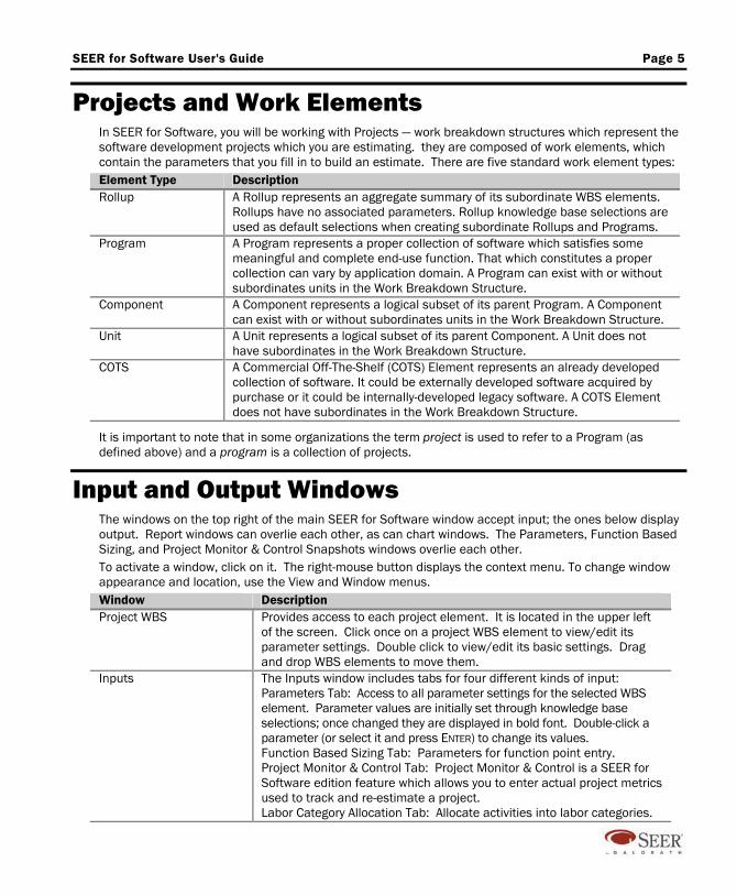
Projects and Work Elements In SEER for Software, you will be working with Projects — work breakdown structures which represent the software development projects which you are estimating. they are composed of work elements, which contain the parameters that you fill in to build an estimate. There are five standard work element types: Element Type Description Rollup A Rollup represents an aggregate summary of its subordinate WBS elements.
Rollups have no associated parameters. Rollup knowledge base selections are used as default selections when creating subordinate Rollups and Programs.
Program A Program represents a proper collection of software which satisfies some meaningful and complete end-use function. That which constitutes a proper collection can vary by application domain. A Program can exist with or without subordinates units in the Work Breakdown Structure.
Component A Component represents a logical subset of its parent Program. A Component can exist with or without subordinates units in the Work Breakdown Structure.
Unit A Unit represents a logical subset of its parent Component. A Unit does not have subordinates in the Work Breakdown Structure.
COTS A Commercial Off-The-Shelf (COTS) Element represents an already developed collection of software. It could be externally developed software acquired by purchase or it could be internally-developed legacy software. A COTS Element does not have subordinates in the Work Breakdown Structure.
It is important to note that in some organizations the term project is used to refer to a Program (as defined above) and a program is a collection of projects.
Input and Output Windows The windows on the top right of the main SEER for Software window accept input; the ones below display output. Report windows can overlie each other, as can chart windows. The Parameters, Function Based Sizing, and Project Monitor & Control Snapshots windows overlie each other. To activate a window, click on it. The right-mouse button displays the context menu. To change window appearance and location, use the View and Window menus. Window Description Project WBS Provides access to each project element. It is located in the upper left
of the screen. Click once on a project WBS element to view/edit its parameter settings. Double click to view/edit its basic settings. Drag and drop WBS elements to move them.
Inputs The Inputs window includes tabs for four different kinds of input: Parameters Tab: Access to all parameter settings for the selected WBS element. Parameter values are initially set through knowledge base selections; once changed they are displayed in bold font. Double-click a parameter (or select it and press ENTER) to change its values. Function Based Sizing Tab: Parameters for function point entry. Project Monitor & Control Tab: Project Monitor & Control is a SEER for Software edition feature which allows you to enter actual project metrics used to track and re-estimate a project. Labor Category Allocation Tab: Allocate activities into labor categories.
Page 6 SEER for Software User’s Guide
Reports and Charts To view one of the currently displayed reports or charts, click on its tab in the Reports or Charts window. If there are too many displayed reports or charts for all of the tabs to be visible at once, you can use the < and > buttons to cycle between the tabs. To display each report and chart tab in a different color, select View / Multi-color Tabs so that it is checked. To view a report or chart in a separate window, select Copy to Window from the tab bar's right-click menu. To display a report or chart, select Choose Active from the appropriate menu. To update reports and charts, press F9 or select Calculate Now from the Estimate menu or the toolbar. Use Options / Automatic Recalculation to automatically recalculate.
Views The Views Selector (lower left corner of the screen) displays views (collections of reports and charts) listed according to category. Changing the view never adds, modifies, or removes project information; it only changes the display. Use View / Create New View to create new views.
Estimating with SEER for Software When you use SEER for Software, you start by determining what your project will consist of, and creating a basic description of the system and development environment. SEER for Software's knowledge bases allow you to make early estimates for cost, schedule, risk and staffing. As more detailed information becomes available, this information should be added to the estimate via the appropriate parameters. As the parameters become more refined, SEER uses this information to refine the estimate. Start with a plan. Organize the information for each element (software entity) in your project. You can work with partial or incomplete data by using SEER’s knowledge bases. Create the first estimate. You can refine it as you learn more about the project. To run an initial estimate, follow these steps: 1. Create your new project file. You begin by creating a new project file.
Define your WBS elements. SEER for Software uses a Work Breakdown Structure (WBS) to model projects. Break down your project into one or more programs. (If limited information is available for the project breakdown, use the parameter, “Programs Included in Size”; this allows estimation of multiple programs as one WBS element.) A program is the highest-level unit of an application, and generally can run independently, or stand alone. It is usually developed by a single team, within a budgeted schedule, often with separate documentation. You can also define rollups (summation points) and divide programs into other elements: Components, Units, and Commercial Off-the-Shelf (COTS) elements.
2. Choose knowledge bases. Knowledge bases are SEER's way of letting you define parameter data for a software element at a very rough level.
3. Enter size. At this point, all you have to do is enter the size of the software in lines, functions, or proxies (alternative size metrics defined by the user) for each element you have defined. SEER for Software will estimate factors such as effort, cost, schedule, staffing, and maintenance.
Project Assistant The SEER-SEM Project Assistant is a utility which allows you to quickly create a new project, or add Program, Component, and COTS work elements to an existing project. It is structured like a wizard, with individual tabs, or pages, which guide you through the necessary steps: selecting knowledge bases, determining the sizing method, sizing, reviewing the estimate, and sending the work elements to SEER-SEM. You can create both sized and unsized work elements with Project Assistant. To use the Project Assistant, click on the Project Assistant button on the SEER-SEM toolbar, or the Switch to Wizard button on the upper left-hand corner of the Create/Modify WBS Element dialog box.

SEER for Software User's Guide Page 7
Edition Features and Optional Add-ons The following edition-specific features and optional add-ons are available for SEER for Software:
Edition Features Estimate by Comparison Microsoft Project Integration Project Monitor & Control Metrics Analysis & Benchmarking ProjectMiner
Optional Add-ons IBM RSX and Rose Adapter IBM RPM Adapter Enterprise Project Database
Please contact Galorath Incorporated's Sales department or go to www.galorath.com for more information about these features.
SEER for Software Knowledge Bases A knowledge base is a set of parameter values, based on actual project, requirement, and environment data similar to your estimating scenario, which can be used to initialize values in your WBS elements. Knowledge bases can be customized to reflect your organization's development history, environment, and requirements. SEER for Software comes with a comprehensive set of knowledge bases organized into six categories. The knowledge bases delivered with SEER for Software are described in the following sections.
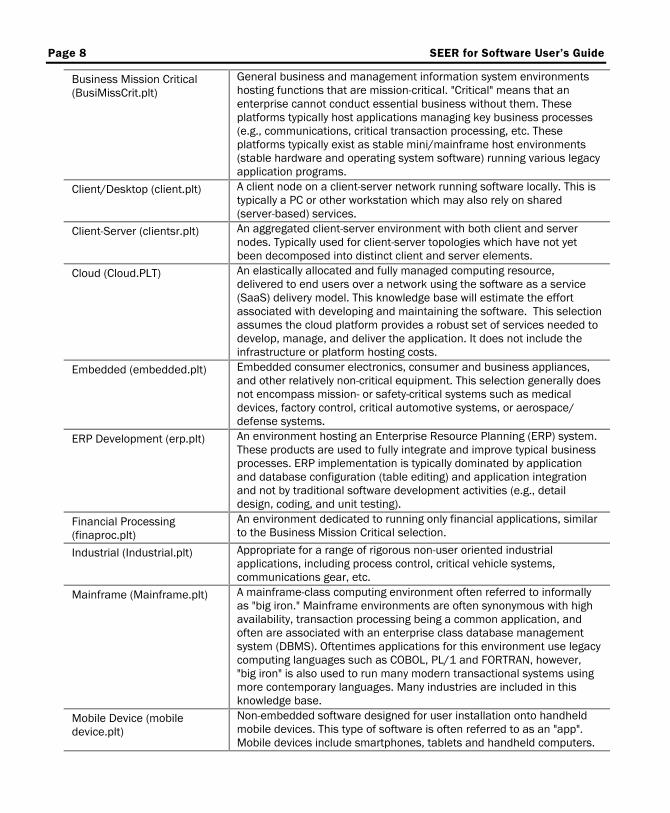
Platform Knowledge Bases Platform knowledge bases describe the primary mission or operating environment of the software.
Knowledge Base Description
Business and Non-Critical MIS (business.plt)
General business and management information system environments hosting functions which are not mission-critical. "Not critical" means that an enterprise can conduct essential business without them. These environments typically host applications supporting back office business processes that can tolerate disruption (human resources, finance, logistics, etc.). These platforms typically exist as stable mini/mainframe host environments (stable hardware and operating system software) running various legacy application programs.
Page 8 SEER for Software User’s Guide
Business Mission Critical (BusiMissCrit.plt)
General business and management information system environments hosting functions that are mission-critical. "Critical" means that an enterprise cannot conduct essential business without them. These platforms typically host applications managing key business processes (e.g., communications, critical transaction processing, etc. These platforms typically exist as stable mini/mainframe host environments (stable hardware and operating system software) running various legacy application programs.
Client/Desktop (client.plt) A client node on a client-server network running software locally. This is typically a PC or other workstation which may also rely on shared (server-based) services.
Client-Server (clientsr.plt) An aggregated client-server environment with both client and server nodes. Typically used for client-server topologies which have not yet been decomposed into distinct client and server elements.
Cloud (Cloud.PLT) An elastically allocated and fully managed computing resource, delivered to end users over a network using the software as a service (SaaS) delivery model. This knowledge base will estimate the effort associated with developing and maintaining the software. This selection assumes the cloud platform provides a robust set of services needed to develop, manage, and deliver the application. It does not include the infrastructure or platform hosting costs.
Embedded (embedded.plt) Embedded consumer electronics, consumer and business appliances, and other relatively non-critical equipment. This selection generally does not encompass mission- or safety-critical systems such as medical devices, factory control, critical automotive systems, or aerospace/ defense systems.
ERP Development (erp.plt) An environment hosting an Enterprise Resource Planning (ERP) system. These products are used to fully integrate and improve typical business processes. ERP implementation is typically dominated by application and database configuration (table editing) and application integration and not by traditional software development activities (e.g., detail design, coding, and unit testing).
Financial Processing (finaproc.plt)
An environment dedicated to running only financial applications, similar to the Business Mission Critical selection.
Industrial (Industrial.plt) Appropriate for a range of rigorous non-user oriented industrial applications, including process control, critical vehicle systems, communications gear, etc.
Mainframe (Mainframe.plt) A mainframe-class computing environment often referred to informally as "big iron." Mainframe environments are often synonymous with high availability, transaction processing being a common application, and often are associated with an enterprise class database management system (DBMS). Oftentimes applications for this environment use legacy computing languages such as COBOL, PL/1 and FORTRAN, however, "big iron" is also used to run many modern transactional systems using more contemporary languages. Many industries are included in this knowledge base.
Mobile Device (mobile device.plt)
Non-embedded software designed for user installation onto handheld mobile devices. This type of software is often referred to as an "app". Mobile devices include smartphones, tablets and handheld computers.
SEER for Software User's Guide Page 9
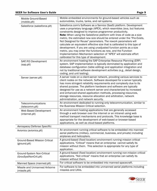
Mobile Ground-Based (mobile.plt)
Mobile embedded environments for ground-based vehicles such as automobiles, trucks, tanks, and rail systems.
Salesforce (salesforce.plt) Salesforce.com's Software as a Service (SaaS) platform. Development uses a proprietary language (APEX), which resembles Java, but features constraints designed to improve programmer productivity. Note: When using the Salesforce platform with lines of code as a size metric, the estimated new size should be entered under the "Pre-Exists, Not Designed for Reuse" parameters. The rework parameters will calculate an equivalent effective size that is calibrated to this type of development. If you are using unadjusted function points as a size metric, you may enter the functions as new, and the Function Implementation Mechanism selection of "APEX" will estimate effort calibrated for this type of development.
SAP/R3 Development (sap.plt)
An environment hosting the SAP Enterprise Resource Planning (ERP) system. SAP implementation is typically dominated by application and database configuration (table editing) and application integration and not by traditional software development activities (e.g., detail design, coding, and unit testing).
Server (server.plt) A server node on a client-server network, providing various services to client nodes on the network. Software developed for a server typically has more stringent reliability requirements and complexity due to its shared purpose. The platform hardware and software are typically designed for use as a network server and characterized by increased and enhanced shared application methods, processing resources, storage resources, resource allocation and arbitration, network administration, and network security.
Telecommunications (telecomm.plt)
An environment dedicated to running only telecommunication, similar to the Business Mission Critical selection.
Web Based Development (internet.plt)
An environment hosting applications that are generally accessed through a web browser over the internet or an intranet using web method transport mechanisms and protocols. This knowledge base is appropriate for the development of web-based or browser-based applications, as well as cloud-based platforms.
Aerospace/Defense Specific: Avionics (avionics.plt) An environment running critical software to be embedded into manned
aerial platforms (military, commercial, business, and private) including airplanes and helicopters.
Ground-Based Mission Critical (ground.plt)
A ground-based (fixed location) environment running mission critical applications. "Critical" means that an enterprise cannot satisfy its mission without them. This selection is appropriate for any type of application.
Ground-System Non-Critical (GrouSystNonCrit.plt)
A ground-based (fixed location) environment running non-mission critical applications. "Not critical" means that an enterprise can satisfy its mission without them.
Manned Space (manned.plt) For critical software to be embedded into manned spacecraft.
Missile and Unmanned Airborne (missile.plt)
For software to be embedded into unmanned aerial platforms including missiles and UAVs.
Page 10 SEER for Software User’s Guide
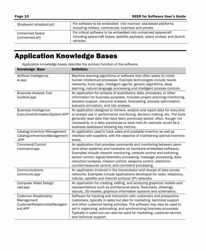
Shipboard (shipbord.plt) For software to be embedded into manned sea-based platforms including military, commercial, business and private.
Unmanned Space (unmanned.plt)
For critical software to be embedded into unmanned spacecraft including spacecraft buses, satellite payloads, space probes, and launch vehicles.
Application Knowledge Bases Application knowledge bases describe the primary function of the software.
Knowledge Base Definition
Artificial Intelligence ai.app
Machine learning algorithms or software that often seeks to mimic human intellectual processes. Example technologies include neural networks, fuzzy logic, intelligent agents, genetic algorithms, deep learning, natural language processing and intelligent process controls.
Business Analysis Tool busitool.app
An application for analysis of quantitative data, processes, or other information for business purposes. Includes project planning/monitoring, decision support, resource analysis, forecasting, process optimization, scenario simulation, and risk analysis.
Business Intelligence ExecutiveInformationSystem.APP
An application designed to retrieve, analyze and report data for executive or analyst use in performance monitoring, decision making, etc. The tools generally read data that have been previously stored, often, though not necessarily, in a data warehouse or data mart.An example would be a business dashboard showing key metrics.
Catalog/Inventory Management CatalogueInventoryManagement.APP
An application used to track sales and available inventory as well as interface with suppliers, with the objective of maintaining optimal inventory levels.
Command/Control command.app
An application that provides commands and monitoring between users (and other systems) and hardware (or hardware-embedded software). Examples include network monitoring, network control and switching, sensor control, signal/telemetry processing, message processing, data reduction/analysis, mission control, weapons control, electronic countermeasures control, and command processing.
Communications communic.app
An application involved in the transmission and receipt of data across networks. Examples include applications developed for radio, telephony, cellular, satellite and internet protocol (IP) networks.
Computer Aided Design cad.app
An application for creating, editing, and analyzing graphical models and representations such as architectural plans, flowcharts, drawings, layouts, 3D models, graphical information systems and schematics.
Customer Relationship Management CustomerRelationshipManagement.APP
Software for tracking and interaction with customers and prospective customers, typically in sales but also for marketing, technical support and other customer-facing activities. The software may also be used to aid in organizing, automating, and synchronizing business processes. Typically in sales but can also be used for marketing, customer service, and technical support.
SEER for Software User's Guide Page 11
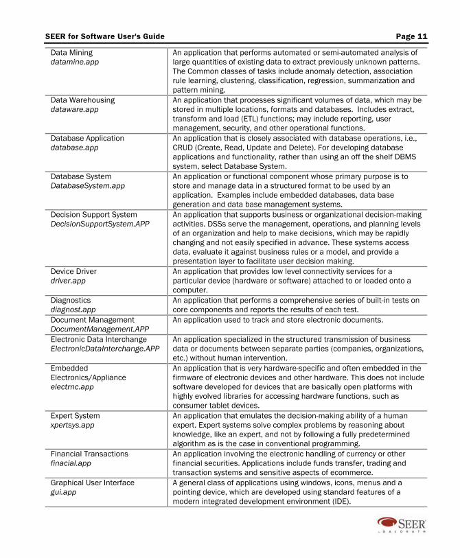
Data Mining datamine.app
An application that performs automated or semi-automated analysis of large quantities of existing data to extract previously unknown patterns. The Common classes of tasks include anomaly detection, association rule learning, clustering, classification, regression, summarization and pattern mining.
Data Warehousing dataware.app
An application that processes significant volumes of data, which may be stored in multiple locations, formats and databases. Includes extract, transform and load (ETL) functions; may include reporting, user management, security, and other operational functions.
Database Application database.app
An application that is closely associated with database operations, i.e., CRUD (Create, Read, Update and Delete). For developing database applications and functionality, rather than using an off the shelf DBMS system, select Database System.
Database System DatabaseSystem.app
An application or functional component whose primary purpose is to store and manage data in a structured format to be used by an application. Examples include embedded databases, data base generation and data base management systems.
Decision Support System DecisionSupportSystem.APP
An application that supports business or organizational decision-making activities. DSSs serve the management, operations, and planning levels of an organization and help to make decisions, which may be rapidly changing and not easily specified in advance. These systems access data, evaluate it against business rules or a model, and provide a presentation layer to facilitate user decision making.
Device Driver driver.app
An application that provides low level connectivity services for a particular device (hardware or software) attached to or loaded onto a computer.
Diagnostics diagnost.app
An application that performs a comprehensive series of built-in tests on core components and reports the results of each test.
Document Management DocumentManagement.APP
An application used to track and store electronic documents.
Electronic Data Interchange ElectronicDataInterchange.APP
An application specialized in the structured transmission of business data or documents between separate parties (companies, organizations, etc.) without human intervention.
Embedded Electronics/Appliance electrnc.app
An application that is very hardware-specific and often embedded in the firmware of electronic devices and other hardware. This does not include software developed for devices that are basically open platforms with highly evolved libraries for accessing hardware functions, such as consumer tablet devices.
Expert System xpertsys.app
An application that emulates the decision-making ability of a human expert. Expert systems solve complex problems by reasoning about knowledge, like an expert, and not by following a fully predetermined algorithm as is the case in conventional programming.
Financial Transactions finacial.app
An application involving the electronic handling of currency or other financial securities. Applications include funds transfer, trading and transaction systems and sensitive aspects of ecommerce.
Graphical User Interface gui.app
A general class of applications using windows, icons, menus and a pointing device, which are developed using standard features of a modern integrated development environment (IDE).
Page 12 SEER for Software User’s Guide
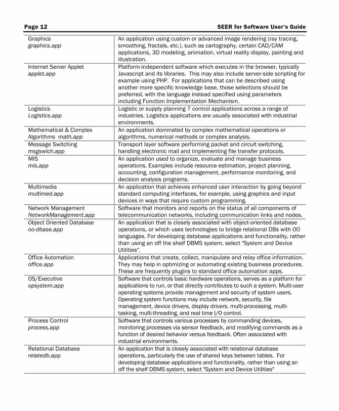
Graphics graphics.app
An application using custom or advanced image rendering (ray tracing, smoothing, fractals, etc.), such as cartography, certain CAD/CAM applications, 3D modeling, animation, virtual reality display, painting and illustration.
Internet Server Applet applet.app
Platform-independent software which executes in the browser, typically Javascript and its libraries. This may also include server-side scripting for example using PHP. For applications that can be described using another more specific knowledge base, those selections should be preferred, with the language instead specified using parameters including Function Implementation Mechanism.
Logistics Logistics.app
Logistic or supply planning 7 control applications across a range of industries. Logistics applications are usually associated with industrial environments.
Mathematical & Complex Algorithms math.app
An application dominated by complex mathematical operations or algorithms, numerical methods or complex analysis.
Message Switching msgswich.app
Transport layer software performing packet and circuit switching, handling electronic mail and implementing file transfer protocols.
MIS mis.app
An application used to organize, evaluate and manage business operations. Examples include resource estimation, project planning, accounting, configuration management, performance monitoring, and decision analysis programs.
Multimedia multimed.app
An application that achieves enhanced user interaction by going beyond standard computing interfaces, for example, using graphics and input devices in ways that require custom programming.
Network Management NetworkManagement.app
Software that monitors and reports on the status of all components of telecommunication networks, including communication links and nodes.
Object Oriented Database oo-dbase.app
An application that is closely associated with object-oriented database operations, or which uses technologies to bridge relational DBs with OO languages. For developing database applications and functionality, rather than using an off the shelf DBMS system, select "System and Device Utilities".
Office Automation office.app
Applications that create, collect, manipulate and relay office information. They may help in optimizing or automating existing business procedures. These are frequently plugins to standard office automation apps.
OS/Executive opsystem.app
Software that controls basic hardware operations, serves as a platform for applications to run, or that directly contributes to such a system. Multi-user operating systems provide management and security of system users. Operating system functions may include network, security, file management, device drivers, display drivers, multi-processing, multi-tasking, multi-threading, and real time I/O control.
Process Control process.app
Software that controls various processes by commanding devices, monitoring processes via sensor feedback, and modifying commands as a function of desired behavior versus feedback. Often associated with industrial environments.
Relational Database relatedb.app
An application that is closely associated with relational database operations, particularly the use of shared keys between tables. For developing database applications and functionality, rather than using an off the shelf DBMS system, select "System and Device Utilities"
SEER for Software User's Guide Page 13
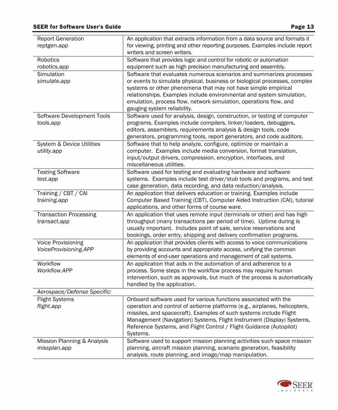
Report Generation reptgen.app
An application that extracts information from a data source and formats it for viewing, printing and other reporting purposes. Examples include report writers and screen writers.
Robotics robotics.app
Software that provides logic and control for robotic or automation equipment such as high precision manufacturing and assembly.
Simulation simulate.app
Software that evaluates numerous scenarios and summarizes processes or events to simulate physical, business or biological processes, complex systems or other phenomena that may not have simple empirical relationships. Examples include environmental and system simulation, emulation, process flow, network simulation, operations flow, and gauging system reliability.
Software Development Tools tools.app
Software used for analysis, design, construction, or testing of computer programs. Examples include compilers, linker/loaders, debuggers, editors, assemblers, requirements analysis & design tools, code generators, programming tools, report generators, and code auditors.
System & Device Utilities utility.app
Software that to help analyze, configure, optimize or maintain a computer. Examples include media conversion, format translation, input/output drivers, compression, encryption, interfaces, and miscellaneous utilities.
Testing Software test.app
Software used for testing and evaluating hardware and software systems. Examples include test driver/stub tools and programs, and test case generation, data recording, and data reduction/analysis.
Training / CBT / CAI training.app
An application that delivers education or training. Examples include Computer Based Training (CBT), Computer Aided Instruction (CAI), tutorial applications, and other forms of course ware.
Transaction Processing transact.app
An application that uses remote input (terminals or other) and has high throughput (many transactions per period of time). Uptime during is usually important. Includes point of sale, service reservations and bookings, order entry, shipping and delivery confirmation programs.
Voice Provisioning VoiceProvisioning.APP
An application that provides clients with access to voice communications by providing accounts and appropriate access, unifying the common elements of end-user operations and management of call systems.
Workflow Workflow.APP
An application that aids in the automation of and adherence to a process. Some steps in the workflow process may require human intervention, such as approvals, but much of the process is automatically handled by the application.
Aerospace/Defense Specific: Flight Systems flight.app
Onboard software used for various functions associated with the operation and control of airborne platforms (e.g., airplanes, helicopters, missiles, and spacecraft). Examples of such systems include Flight Management (Navigation) Systems, Flight Instrument (Display) Systems, Reference Systems, and Flight Control / Flight Guidance (Autopilot) Systems.
Mission Planning & Analysis missplan.app
Software used to support mission planning activities such space mission planning, aircraft mission planning, scenario generation, feasibility analysis, route planning, and image/map manipulation.
Page 14 SEER for Software User’s Guide
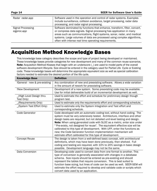
Radar radar.app Software used in the operation and control of radar systems. Examples include surveillance, collision avoidance, target processing, radar data processing, and radar signal processing.
Signal Processing sigproc.app
Software dominated by functions that enhance, transform, filter, convert, or compress data signals. Signal processing has application in many areas such as communications, flight systems, sonar, radar, and medical systems. Large volumes of data are processed using complex algorithms, often with intense real time operating requirements.
Acquisition Method Knowledge Bases This knowledge base category describes the scope and type of project being developed or maintained. These knowledge bases provide categories for new development and many of the common reuse scenarios. Note: Acquisition Method Kbases that begin with an underscore (_) are used to model parts of the overall software development lifecycle. Size should be entered in the category used for Partial Life Cycle or Existing code. These knowledge bases will determine the appropriate equivalent size as well as special calibration factors needed to estimate the desired portion of the life cycle. Knowledge Base Definition
!General - new & pre-existing
Any combination of new and preexisting software. Allows a wide variation in the amount of rework for preexisting software.
!New Development
Development of a new system. Some preexisting code may be available. Use for initial deliverable build of an incremental development as well.
_(High Level Design thru Test Only)
Used to estimate the effort and schedule for preliminary design though program test.
_(Requirements Only) Used to estimate only the requirements effort and corresponding schedule. _(System Test Effort Only) Used to estimate only the System Integration and Test effort and
corresponding schedule. Code Generator
Code developed with an automatic coding tool, without hand coding. The system must be very extensively tested. Architecture, interface and other design tasks are required, but not detailed unit-level testing and design. Note: When using generated code with SLOC as a metric, enter size under " Pre-exists, not designed for reuse". The equivalent effective size will be calibrated to this type of development. With UFP, enter the functions as new; the Code Generator function implementation mechanism will estimate effort calibrated for this type of development.
Concept Reuse
The design is taken from a well-defined basic concept, with architectural definitions, which may have been done previously, then shelved. Full coding and testing are required, with 10% to 20% savings in basic design possible. Development language may not be the same.
Data Conversion
Developing code used to convert data from one format to another. This type of conversion is generally associated with changes in a database schema. Size inputs should be entered as pre-existing and should represent the tables that require conversion. This is best suited to function base sizing, but lines of code can be used as well. SEER-SEM will estimate the effort required to develop and validate code or scripts which convert data used by an application.
SEER for Software User's Guide Page 15
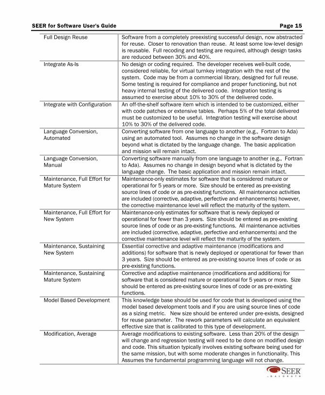
Full Design Reuse
Software from a completely preexisting successful design, now abstracted for reuse. Closer to renovation than reuse. At least some low-level design is reusable. Full recoding and testing are required, although design tasks are reduced between 30% and 40%.
Integrate As-Is
No design or coding required. The developer receives well-built code, considered reliable, for virtual turnkey integration with the rest of the system. Code may be from a commercial library, designed for full reuse. Some testing is required for compliance and proper functioning, but not heavy internal testing of the delivered code. Integration testing is assumed to exercise about 10% to 30% of the delivered code.
Integrate with Configuration
An off-the-shelf software item which is intended to be customized, either with code patches or extensive tables. Perhaps 5% of the total delivered must be customized to be useful. Integration testing will exercise about 10% to 30% of the delivered code.
Language Conversion, Automated
Converting software from one language to another (e.g., Fortran to Ada) using an automated tool. Assumes no change in the software design beyond what is dictated by the language change. The basic application and mission will remain intact.
Language Conversion, Manual
Converting software manually from one language to another (e.g., Fortran to Ada). Assumes no change in design beyond what is dictated by the language change. The basic application and mission remain intact.
Maintenance, Full Effort for Mature System
Maintenance-only estimates for software that is considered mature or operational for 5 years or more. Size should be entered as pre-existing source lines of code or as pre-existing functions. All maintenance activities are included (corrective, adaptive, perfective and enhancements) however, the corrective maintenance level will reflect the maturity of the system.
Maintenance, Full Effort for New System
Maintenance-only estimates for software that is newly deployed or operational for fewer than 3 years. Size should be entered as pre-existing source lines of code or as pre-existing functions. All maintenance activities are included (corrective, adaptive, perfective and enhancements) and the corrective maintenance level will reflect the maturity of the system.
Maintenance, Sustaining New System
Essential corrective and adaptive maintenance (modifications and additions) for software that is newly deployed or operational for fewer than 3 years. Size should be entered as pre-existing source lines of code or as pre-existing functions.
Maintenance, Sustaining Mature System
Corrective and adaptive maintenance (modifications and additions) for software that is considered mature or operational for 5 years or more. Size should be entered as pre-existing source lines of code or as pre-existing functions.
Model Based Development This knowledge base should be used for code that is developed using the model based development tools and if you are using source lines of code as a sizing metric. New size should be entered under pre-exists, designed for reuse parameter. The rework parameters will calculate an equivalent effective size that is calibrated to this type of development.
Modification, Average
Average modifications to existing software. Less than 20% of the design will change and regression testing will need to be done on modified design and code. This situation typically involves existing software being used for the same mission, but with some moderate changes in functionality. This Assumes the fundamental programming language will not change.

Page 16 SEER for Software User’s Guide
Modification, Major
Major modifications to existing software. Design will change up to 30% and regression testing will need to be done on all code. This situation typically involves existing software being used for a new application or mission and often involves a target environment change. This knowledge base assumes the fundamental programming language will not change.
Modification, Minor
Minor modifications to existing software. Less than 10% of the design will change and regression testing will need to be done on modified design and code. This situation typically involves existing software being used for the same mission, but with some changes in functionality. This knowledge base assumes the fundamental programming language will not change.
Redocumentation
Major revisions to the software specifications and manuals. No change is made to the software. Assumes some familiarity with the software, and that some existing documentation (up to 25%) can be used.
Reengineering, Major
Major rework of an existing application to improve program structure, documentation, and maintainability, with moderate amounts of reverse engineering to check program design. The basic functionality remains intact, and the programming language stays the same.
Reengineering, Minor
Minor rework of an existing application to improve program structure and documentation, with the basic functionality of the application remaining intact, and the programming language staying the same.
Rehost, Major
Rehosting software from one target environment to another. Assumes a change in operating systems, target hardware, and development tools. For example, a port of an application from Windows to Linux. Assumes the basic functionality of the application will remain intact, and that the programming language will stay the same.
Rehost, Minor
Rehosting software from one target environment to a similar environment, with no major operating system changes. Platform development tools may be different. For example, a port from an SGI Unix workstation to a Sun Unix workstation. Assumes the basic functionality of the application will remain intact, and that the programming language will stay the same.
Reverse Engineering
Reverse engineer and document existing software. This effort assumes no code change is required. It is applicable to systems that are being reimplemented in some form and generally not by the original developers.
Salesforce This knowledge base should be used for code that is developed using the Salesforce platform with the APEX language, particularly if you are using SLOC as a metric. Enter new size under the " Pre-exists, not designed for reuse" parameters. The rework parameters will calculate an equivalent effective size that is calibrated to this type of development. If you are using UFP as a metric, use of this knowledge base is optional; you may enter the functions as new, and the APEX function implementation mechanism will estimate effort calibrated for this type of development.
Salvage Code
Code salvaged from another application, with heavy redesign and coding to renovate the system. The percent of redesign and recoding is probably more than half, and nearly full retesting is required. Major changes to design, development environment, and even programming language.
Subsequent Incremental Build
A deliverable incremental build other than the initial build. Assumes no requirements work after baseline. Maintenance estimates of subsequent builds are only for the portion of software being added and modified.
SEER for Software User's Guide Page 17
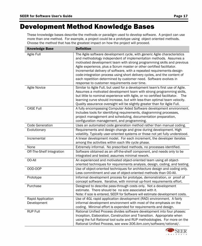
Development Method Knowledge Bases These knowledge bases describe the methods or paradigm used to develop software. A project can use more than one method. For example, a project could be a prototype using object oriented methods. Choose the method that has the greatest impact on how the project will proceed.
Knowledge Base Definition
Agile Full The Agile software development cycle, with generic Agile characteristics and methodology independent of implementation methods. Assumes a motivated development team with strong programming skills and previous Agile experience, plus a Scrum master or other certified facilitator. Incremental delivery of software, with a repeated requirements-design-code-integration process using short delivery cycles, and the content of each repetition determined by customer need. Software evolves in response to customer requirements over time.
Agile Novice Similar to Agile Full, but used for a development team's first use of Agile. Assumes a motivated development team with strong programming skills, but little to nominal experience with Agile, or no certified facilitator. The learning curve should increase, but with less-than optimal team velocity. Quality assurance oversight will be slightly greater than for Agile Full.
CASE Full A fully encompassing Computer Aided Software development environment. Includes tools for identifying requirements, diagramming processes, project management and scheduling, documentation preparation, configuration management, and programming.
Code Generation Uses an automated code generation method rather than manual coding. Evolutionary
Requirements and design change and grow during development. High volatility. Typically user-oriented systems or those not yet fully understood.
Incremental
A linear development model. For each increment, the developer iterates among the activities within each life cycle phase.
None Extremely informal. No prescribed methods, no processes identified. Off-The-Shelf Integration Software obtained as an off-the-shelf component, and needs only to be
integrated and tested; assumes minimal rework. OO-All
An experienced and motivated object-oriented team using all object-oriented techniques for requirements analysis, design, coding, and testing.
OOD-OOP
Use of object-oriented techniques for architecture design and coding only. Less commitment and use of object-oriented methods than OO-All.
Prototype
Informal development process for prototype, demonstration, or proof of concept software. Iterative, with minimal up-front requirements effort.
Purchase
Designed to describe pass-through costs only. Not a development estimate. There should be no size associated with it. Note: if size is entered, SEER for Software will estimate development costs.
Rapid Application Development
Use of 4GL rapid application development (RAD) environment. A fairly informal development environment with most of the emphasis on the coding. Minimal effort is expended for requirements and design.
RUP Full
Rational Unified Process divides software development into four phases: Inception, Elaboration, Construction and Transition. Appropriate when using the full Rational tool suite and RUP methodologies. For more on the Rational Unified Process, see www-306.ibm.com/software/rational/.
Page 18 SEER for Software User’s Guide
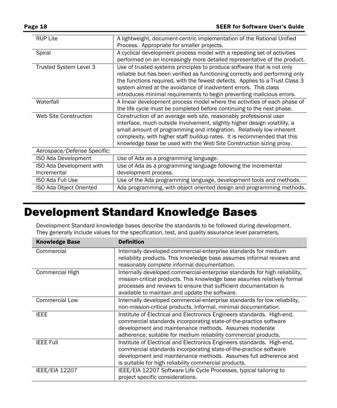
RUP Lite
A lightweight, document-centric implementation of the Rational Unified Process. Appropriate for smaller projects.
Spiral
A cyclical development process model with a repeating set of activities performed on an increasingly more detailed representative of the product.
Trusted System Level 3
Use of trusted systems principles to produce software that is not only reliable but has been verified as functioning correctly and performing only the functions required, with the fewest defects. Applies to a Trust Class 3 system aimed at the avoidance of inadvertent errors. This class introduces minimal requirements to begin preventing malicious errors.
Waterfall
A linear development process model where the activities of each phase of the life cycle must be completed before continuing to the next phase.
Web Site Construction
Construction of an average web site, reasonably professional user interface, much outside involvement, slightly higher design volatility, a small amount of programming and integration. Relatively low inherent complexity, with higher staff buildup rates. It is recommended that this knowledge base be used with the Web Site Construction sizing proxy.
Aerospace/Defense Specific: ISO Ada Development Use of Ada as a programming language. ISO Ada Development with Incremental
Use of Ada as a programming language following the incremental development process.
ISO Ada Full Use Use of the Ada programming language, development tools and methods. ISO Ada Object Oriented Ada programming, with object oriented design and programming methods.
Development Standard Knowledge Bases Development Standard knowledge bases describe the standards to be followed during development. They generally include values for the specification, test, and quality assurance level parameters.
Knowledge Base Definition
Commercial
Internally developed commercial-enterprise standards for medium reliability products. This knowledge base assumes informal reviews and reasonably complete informal documentation.
Commercial High
Internally developed commercial-enterprise standards for high reliability, mission-critical products. This knowledge base assumes relatively formal processes and reviews to ensure that sufficient documentation is available to maintain and update the software.
Commercial Low
Internally developed commercial-enterprise standards for low reliability, non-mission-critical products. Informal, minimal documentation.
IEEE
Institute of Electrical and Electronics Engineers standards. High-end, commercial standards incorporating state-of-the-practice software development and maintenance methods. Assumes moderate adherence; suitable for medium reliability commercial products.
IEEE Full
Institute of Electrical and Electronics Engineers standards. High-end, commercial standards incorporating state-of-the-practice software development and maintenance methods. Assumes full adherence and is suitable for high reliability commercial products.
IEEE/EIA 12207
IEEE/EIA 12207 Software Life Cycle Processes, typical tailoring to project specific considerations.

SEER for Software User's Guide Page 19
IS Formal
Business information systems developed using formalized standards for documentation, testing, quality assurance, configuration management, and/or reviews. Associated with high reliability business information systems where uptime is a critical operational feature.
IS Relaxed
Business information systems developed using informal standards for documentation, testing, quality assurance, configuration management and or reviews. Associated with business information systems where uptime is not a critical operational feature.
ISO 9001
Software meeting the International Standards Organization (ISO) quality standard 9001, using ISO 9000-3 guidelines for software systems.
MIS-HI High reliability business information systems. Uptime is critical. MIS-LO
Internally developed commercial-enterprise-style standards for medium reliability business information systems development. This knowledge base assumes uptime not to be a critical operational feature.
No Standard Being Followed
No generally accepted standards are being followed during development. Absolute minimal specification and testing.
SPICE (Software Process Improvement and Capability dEtermination)
SPICE (ISO/IEC 15504) is an alternative to the maturity models for determining an organization's ability to deliver products. Based on ISO 12207, it is a "framework for the assessment of processes" developed by the Joint Technical Subcommittee between ISO and IEC.
Aerospace/Defense Specific: 1679 with IV&V
U. S. Navy Standard 1679 will be followed during the development, and strict independent verification and validation (IV&V) will be required.
2167A
U. S. DoD Standard 2167A will be followed during the development, with some tailoring for cost reduction or reliability requirements.
2167A Full Set
U. S. DoD Standard 2167A will be followed during the development. Full set, no tailoring.
2167A Minimal Set
U. S. DoD Standard 2167A will be followed during the development. Tailored to be similar to a high-end commercial specification.
498 Business Systems
Mil-Std-498 with appropriate tailoring for business systems will be followed during the development.
498 Support Systems
Mil-Std-498 with appropriate tailoring for non-mission critical weapons systems and support systems. Reliability is important, but consequence of failure is not as great as the 498 Weapons Systems classification.
498 Weapons Systems
Mil-Std-498 with appropriate tailoring for mission critical weapons systems. Reliability is very important.
ANSI J-STD-016 Full
A minimally tailored version of ANSI J-STD-016 Software Development and Documentation (a commercial version of MIL-STD-498), developed and published by IEEE and EIA, adopted by the American National Standards Institute (ANSI), and considered appropriate for high reliability systems. Examples of such systems include aircraft, space systems, weapons systems, and mission critical systems.
ANSI J-STD-016 Min
An extensively tailored version of ANSI J-STD-016 Software Development and Documentation (a commercial version of MIL-STD-498), developed and published by IEEE and EIA, adopted by the American National Standards Institute (ANSI), and considered appropriate for low reliability systems. Examples: business data processing and low-end commercial products.
Page 20 SEER for Software User’s Guide
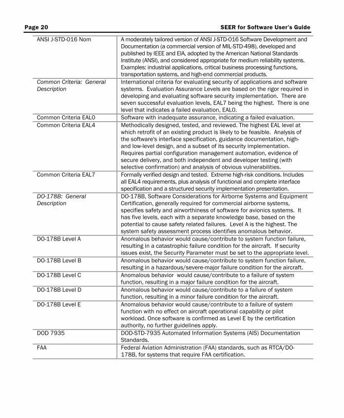
ANSI J-STD-016 Nom
A moderately tailored version of ANSI J-STD-016 Software Development and Documentation (a commercial version of MIL-STD-498), developed and published by IEEE and EIA, adopted by the American National Standards Institute (ANSI), and considered appropriate for medium reliability systems. Examples: industrial applications, critical business processing functions, transportation systems, and high-end commercial products.
Common Criteria: General Description
International criteria for evaluating security of applications and software systems. Evaluation Assurance Levels are based on the rigor required in developing and evaluating software security implementation. There are seven successful evaluation levels, EAL7 being the highest. There is one level that indicates a failed evaluation, EAL0.
Common Criteria EAL0 Software with inadequate assurance, indicating a failed evaluation. Common Criteria EAL4
Methodically designed, tested, and reviewed. The highest EAL level at which retrofit of an existing product is likely to be feasible. Analysis of the software's interface specification, guidance documentation, high- and low-level design, and a subset of its security implementation. Requires partial configuration management automation, evidence of secure delivery, and both independent and developer testing (with selective confirmation) and analysis of obvious vulnerabilities.
Common Criteria EAL7
Formally verified design and tested. Extreme high-risk conditions. Includes all EAL4 requirements, plus analysis of functional and complete interface specification and a structured security implementation presentation.
DO-178B: General Description
DO-178B, Software Considerations for Airborne Systems and Equipment Certification, generally required for commercial airborne systems, specifies safety and airworthiness of software for avionics systems. It has five levels, each with a separate knowledge base, based on the potential to cause safety related failures. Level A is the highest. The system safety assessment process identifies anomalous behavior.
DO-178B Level A
Anomalous behavior would cause/contribute to system function failure, resulting in a catastrophic failure condition for the aircraft. If security issues exist, the Security Parameter must be set to the appropriate level.
DO-178B Level B
Anomalous behavior would cause/contribute to system function failure, resulting in a hazardous/severe-major failure condition for the aircraft.
DO-178B Level C
Anomalous behavior would cause/contribute to a failure of system function, resulting in a major failure condition for the aircraft.
DO-178B Level D
Anomalous behavior would cause/contribute to a failure of system function, resulting in a minor failure condition for the aircraft.
DO-178B Level E
Anomalous behavior would cause/contribute to a failure of system function with no effect on aircraft operational capability or pilot workload. Once software is confirmed as Level E by the certification authority, no further guidelines apply.
DOD 7935
DOD-STD-7935 Automated Information Systems (AIS) Documentation Standards.
FAA
Federal Aviation Administration (FAA) standards, such as RTCA/DO-178B, for systems that require FAA certification.
SEER for Software User's Guide Page 21
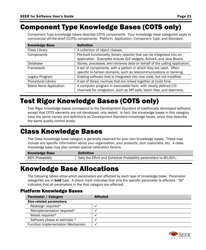
Component Type Knowledge Bases (COTS only) Component Type knowledge bases describe COTS components. Four knowledge base categories apply to commercial off-the-shelf (COTS) components: Platform, Application, Component Type, and Standard.
Knowledge Base Definition Class Library A collection of object classes. Components
Pre-built functionality (binary objects) that can be integrated into an application. Examples include GUI widgets, ActiveX, and Java Beans.
Database Stores, processes, and retrieves data on behalf of the calling application. Framework
A set of components, with a pattern in which they are used. Often specific to certain domains, such as telecommunications or banking.
Legacy Program Existing software that is integrated into new code, but not modified. Procedural Library A set of library routines that are linked together at build time. Stand Alone Application
A computer program in executable form, with clearly defined I/O channels for integration, such as API calls, batch files, and daemons.
Test Rigor Knowledge Bases (COTS only) Test Rigor knowledge bases correspond to the Development Standard of traditionally developed software, except that COTS elements are not developed, only tested. In fact, the knowledge bases in this category have the same names and definitions as Development Standard knowledge bases, since they describe the same quality control levels.
Class Knowledge Bases The Class knowledge base category is generally reserved for your own knowledge bases. These may include any specific information about your organization, your products, your customers, etc. A class knowledge base may also contain special calibration factors.
Knowledge Base Definition 80% Probability Sets the Effort and Schedule Probability parameters to 80.00%.
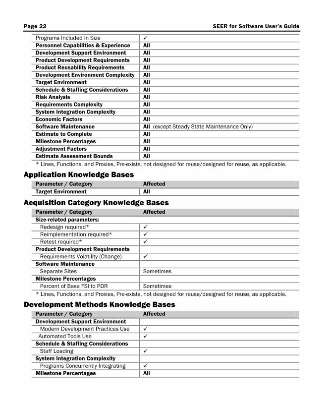
Knowledge Base Allocations The following tables show which parameters are affected by each type of knowledge base. Parameter categories are in bold type. A check mark indicates that only the specific parameter is affected. "All" indicates that all parameters in the that category are affected.
Platform Knowledge Bases Parameter / Category Affected Size-related parameters: Redesign required* Reimplementation required* Retest required* Software phase at estimate * Function Implementation Mechanism
Page 22 SEER for Software User’s Guide
Programs Included In Size Personnel Capabilities & Experience All Development Support Environment All Product Development Requirements All Product Reusability Requirements All Development Environment Complexity All Target Environment All Schedule & Staffing Considerations All Risk Analysis All Requirements Complexity All System Integration Complexity All Economic Factors All Software Maintenance All (except Steady State Maintenance Only) Estimate to Complete All Milestone Percentages All Adjustment Factors All Estimate Assessment Bounds All * Lines, Functions, and Proxies, Pre-exists, not designed for reuse/designed for reuse, as applicable.
Application Knowledge Bases Parameter / Category Affected Target Environment All
Acquisition Category Knowledge Bases Parameter / Category Affected Size-related parameters: Redesign required* Reimplementation required* Retest required* Product Development Requirements Requirements Volatility (Change) Software Maintenance Separate Sites Sometimes Milestone Percentages Percent of Base FSI to PDR Sometimes * Lines, Functions, and Proxies, Pre-exists, not designed for reuse/designed for reuse, as applicable.
Development Methods Knowledge Bases Parameter / Category Affected Development Support Environment Modern Development Practices Use Automated Tools Use Schedule & Staffing Considerations Staff Loading System Integration Complexity Programs Concurrently Integrating Milestone Percentages All
SEER for Software User's Guide Page 23
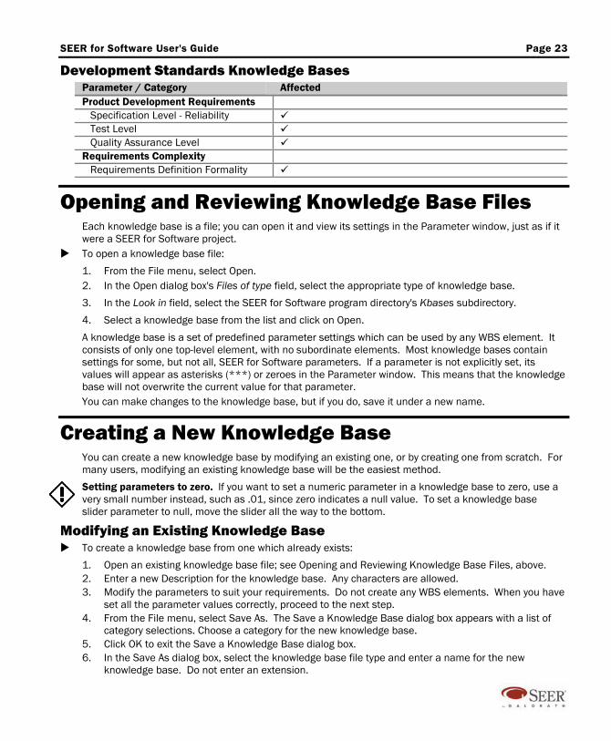
Development Standards Knowledge Bases Parameter / Category Affected Product Development Requirements Specification Level - Reliability Test Level Quality Assurance Level Requirements Complexity Requirements Definition Formality
Opening and Reviewing Knowledge Base Files Each knowledge base is a file; you can open it and view its settings in the Parameter window, just as if it were a SEER for Software project.
To open a knowledge base file:
1. From the File menu, select Open. 2. In the Open dialog box's Files of type field, select the appropriate type of knowledge base.
3. In the Look in field, select the SEER for Software program directory's Kbases subdirectory.
4. Select a knowledge base from the list and click on Open.
A knowledge base is a set of predefined parameter settings which can be used by any WBS element. It consists of only one top-level element, with no subordinate elements. Most knowledge bases contain settings for some, but not all, SEER for Software parameters. If a parameter is not explicitly set, its values will appear as asterisks (***) or zeroes in the Parameter window. This means that the knowledge base will not overwrite the current value for that parameter. You can make changes to the knowledge base, but if you do, save it under a new name.
Creating a New Knowledge Base You can create a new knowledge base by modifying an existing one, or by creating one from scratch. For many users, modifying an existing knowledge base will be the easiest method.
Setting parameters to zero. If you want to set a numeric parameter in a knowledge base to zero, use a very small number instead, such as .01, since zero indicates a null value. To set a knowledge base slider parameter to null, move the slider all the way to the bottom.
Modifying an Existing Knowledge Base To create a knowledge base from one which already exists:
1. Open an existing knowledge base file; see Opening and Reviewing Knowledge Base Files, above. 2. Enter a new Description for the knowledge base. Any characters are allowed. 3. Modify the parameters to suit your requirements. Do not create any WBS elements. When you have
set all the parameter values correctly, proceed to the next step. 4. From the File menu, select Save As. The Save a Knowledge Base dialog box appears with a list of
category selections. Choose a category for the new knowledge base. 5. Click OK to exit the Save a Knowledge Base dialog box. 6. In the Save As dialog box, select the knowledge base file type and enter a name for the new
knowledge base. Do not enter an extension.
Page 24 SEER for Software User’s Guide
Creating a New Knowledge Base from Scratch To create a knowledge base from scratch:
1. From the File menu, select New. The Create/Modify WBS Element dialog box appears. Do not make knowledge base selections.
2. Enter a Description for the knowledge base. Any characters are allowed. Click OK to exit the Create/Modify WBS Element dialog box.
3. From the Estimate menu, select Clear Kbase to No Knowledge. This erases all parameter values, setting them to appear as asterisks (***) or zeroes. If you do not use Clear Kbase to No Knowledge, parameters such as Analyst Capabilities will retain their default nominal values (Nom-Nom-Nom) and will overwrite existing parameter values when loaded.
4. Enter the parameter values for your knowledge base, as you would enter them for a project. Do not create any WBS elements. When you have set all the parameter values correctly, proceed to the next step.
5. From the File menu, select Save As. Follow the steps for saving a knowledge base, as described in steps 4, 5, and 6 in Modifying an Existing Knowledge Base, above.
Whichever method you use, the next time you create a new project or WBS element, your new knowledge base should appear in the category to which you assigned it. If it doesn't, make sure it was saved in the Kbases subdirectory with the standard category extension.
SEER for Software Parameters Parameter data is the basis of a SEER estimate. You will enter some parameter values directly. Other parameters get their values from knowledge bases, or are calculated from lower-level parameters.
Sizing Parameters Sizing with SEER for Software allows for different size metrics to be entered in different size categories. Metrics. SEER for Software size metrics include Lines of Code, Functions, and any number of user defined metrics found under the Proxy Sizing inputs. Each metric has a major section in the parameter list.
Lines of code are executable source instructions, as defined in the Sizing in SEER for Software / Source Lines of Code section of this manual. Functions represent the basic types of operation performed by the code, rather than the code itself. They are divided into five categories (as defined by IFPUG): External Inputs, External Outputs, External Inquiries, External Interface Files, and Internal Logical Files. SEER for Software adds a sixth category, Internal Functions. Proxies are pre-defined relationships for measuring software size. SEER for Software includes several pre-defined proxies. You can also define your own proxies. See also: Sizing in SEER for Software, in this manual.
Categories. SEER for Software size categories include new code, and two types of pre-existing code. New code is code built from scratch; pre-existing code already exists, and will be reused, with some degree of modification. The pre-existing code categories may also used for estimating special circumstances, such as generated code and test-only activities.
There are two categories of pre-existing code: Pre-exists, designed for reuse, and Pre-exists, not designed for reuse. Pre-existing code which was designed for reuse generally requires significantly less rework than that which was not designed for reuse.
SEER for Software User's Guide Page 25
For pre-existing code which will be used with little or no modification, a COTS work element (which includes its own sizing parameters) may be more appropriate. Click on the “+” next to a category's name to see its parameter list. You can use more than one metric, but be careful to count each unit of software only once.
Sizing Categories There are three categories of sizing parameters, representing each metric type: LINES (Classic), FUNCTIONS (Classic), and PROXY SIZING. The parameters listed below appear in one or more of these categories, as indicated. Enter parameters at the lowest element level (Units, Components, Program). Functions: When you select a sizing parameter in the Functions category, the program asks if you want to switch to the Function Based Sizing (FBS) window. If you use the FBS window, SEER for Software will calculate the UFPs (Unadjusted Function Points).
Proxy Description The proxy sizing parameter list will vary, depending on your choice of proxy; it can include up to ten additional parameters. See Sizing in SEER for Software / Proxy Sizing for a description of standard SEER for Software proxies. Applies to Proxies.
NEW Parameters in this category should be entered at the lowest element level. New software is any new functionality/software that is built from scratch. Applies to Functions and Proxies.
New Lines of Code / Functions / proxy units The number of effective lines, IFPUG unadjusted function points (UFPs), or proxy units that will be completely developed (designed, implemented and tested) from scratch. This also includes new functionality that will be added to existing code. Functions: If you enter functions in the FBS window, their sum will appear here. Applies to Lines, Functions, and Proxies.
Size Growth Factor Note: Enable Size Growth Factors must be checked in the Project Parameters dialog box. Multiplier for expected size growth beyond entered size. The default Size Growth Factor is 1.0. You can enter any Size Growth Factor from 0.1 to 10.0. Lines (Classic), Functions (Classic), and Proxy Sizing.
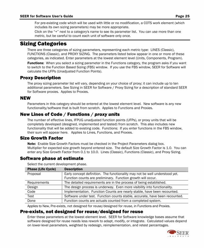
Software phase at estimate Select the current development phase. Phase (Life Cycle) Description Proposal Early concept definition. The functionality may not be well understood yet.
Function counts are preliminary. Function growth will occur. Requirements The detailed requirements are in the process of being established. Design The design process is underway. Even more visibility into functionality. Code Implementation. Function Counts are nearly stable, have been recounted. Test Software under test. Function counts stable, accurate, have been recounted. Done Function counts are actuals counted from a completed system.
Applies to New, Pre-exists, not designed for reuse/designed for reuse, in Functions and Proxies.
Pre-exists, not designed for reuse/designed for reuse Enter these parameters at the lowest element level. SEER for Software knowledge bases assume that software designed for reuse needs less rework to adapt, modify, or integrate. Calculated values depend on lower-level parameters, weighted by redesign, reimplementation, and retest percentages.
Page 26 SEER for Software User’s Guide
Pre-existing lines of code / functions / proxy units The number of effective lines, UFPs, or proxy units of reused code. This is the computed effective size rather than an input. Include code that will be copied and subsequently may be deleted. When estimating incremental developments, measure the delivered size from the prior increment. Applies to Pre-exists, not designed for reuse/designed for reuse, in Lines, Functions, and Proxies.
Lines / Funcs to be deleted in pre-existing Number of lines of code or UFPs that will be deleted outright before any work begins. These have been included in the Pre-existing lines of code parameter and are simply discarded before any calculations begin. SEER for Software does not calculate any effort to delete pre-existing code. Applies to Pre-exists, not designed for reuse/designed for reuse, in Lines and Functions.
Redesign required The percentage of existing software that must be redesigned to make the reused software functional, or the changes to the overall design or system architecture that will be required to reuse the existing design. Include amounts that must be learned or reverse engineered, redocumented or revalidated, as well as the actual amount of redesign work. Applies to Pre-exists, not designed for reuse/designed for reuse, in Lines, Functions, and Proxies.
Reimplementation required Estimate the percentage of existing software that must be coded and tested at the unit level. Include portions that must be learned or reverse engineered. Applies to Pre-exists, not designed for reuse/designed for reuse, in Lines, Functions, and Proxies.
Retest required The percentage of existing software requiring integration testing, component testing, and program testing. Applies to Pre-exists, not designed for reuse/designed for reuse, in Lines, Functions, and Proxies.
Function Implementation Mechanism This parameter is set at the lowest WBS element level defined (e.g., Program, Component, or Unit). It describes the programming language or the implementation mechanism, such as a code generator or screen generator, which will be used to build the current element. For function-based estimates, language can have a major impact on effort. The choice of language can also affect defect estimates for both line- and function-based estimates, since some languages are more defect-prone than others. If you select a new language in a WBS element's Function Implementation Mechanism parameter, the Function Implementation Change dialog box will appear.
Programs Included In Size Defined at the Program WBS element level. Enter the number of stand-alone programs included. Most estimates will use the default value of one (1). For early or system-level estimation where you know system-level sizing only, enter the estimated number of programs (even those by separate teams, with their own schedules and documentation).
Technology and Environment Parameters Most parameters are rated on a scale ranging from very low to extra high, with +/- gradations, and will accept three estimates, in Least, Likely, Most format: least likely, most likely, and most optimistic.
PERSONNEL CAPABILITIES & EXPERIENCE Parameters in this category are available only at the Program level.
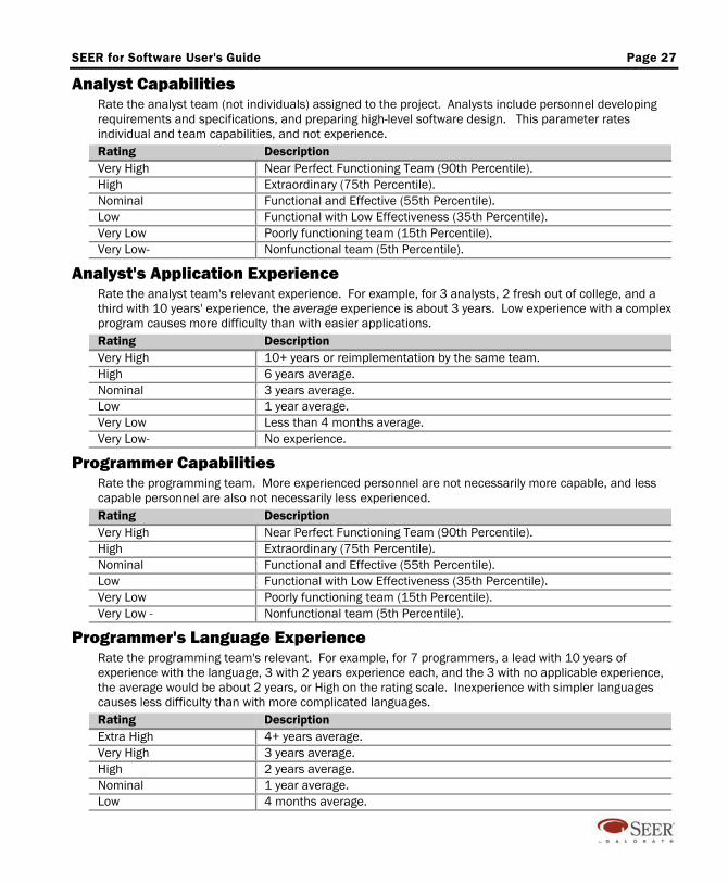
SEER for Software User's Guide Page 27
Analyst Capabilities Rate the analyst team (not individuals) assigned to the project. Analysts include personnel developing requirements and specifications, and preparing high-level software design. This parameter rates individual and team capabilities, and not experience. Rating Description Very High Near Perfect Functioning Team (90th Percentile). High Extraordinary (75th Percentile). Nominal Functional and Effective (55th Percentile). Low Functional with Low Effectiveness (35th Percentile). Very Low Poorly functioning team (15th Percentile). Very Low- Nonfunctional team (5th Percentile).
Analyst's Application Experience Rate the analyst team's relevant experience. For example, for 3 analysts, 2 fresh out of college, and a third with 10 years' experience, the average experience is about 3 years. Low experience with a complex program causes more difficulty than with easier applications. Rating Description Very High 10+ years or reimplementation by the same team. High 6 years average. Nominal 3 years average. Low 1 year average. Very Low Less than 4 months average. Very Low- No experience.
Programmer Capabilities Rate the programming team. More experienced personnel are not necessarily more capable, and less capable personnel are also not necessarily less experienced. Rating Description Very High Near Perfect Functioning Team (90th Percentile). High Extraordinary (75th Percentile). Nominal Functional and Effective (55th Percentile). Low Functional with Low Effectiveness (35th Percentile). Very Low Poorly functioning team (15th Percentile). Very Low - Nonfunctional team (5th Percentile).
Programmer's Language Experience Rate the programming team's relevant. For example, for 7 programmers, a lead with 10 years of experience with the language, 3 with 2 years experience each, and the 3 with no applicable experience, the average would be about 2 years, or High on the rating scale. Inexperience with simpler languages causes less difficulty than with more complicated languages. Rating Description Extra High 4+ years average. Very High 3 years average. High 2 years average. Nominal 1 year average. Low 4 months average.
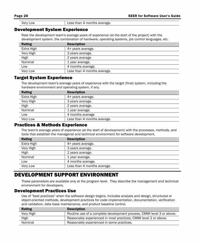
Page 28 SEER for Software User’s Guide
Very Low Less than 4 months average.
Development System Experience Rate the development team's average years of experience (at the start of the project) with the development system, the combination of hardware, operating systems, job control languages, etc. Rating Description Extra High 4+ years average. Very High 3 years average. High 2 years average Nominal 1 year average. Low 4 months average. Very Low Less than 4 months average.
Target System Experience The development team's average years of experience with the target (final) system, including the hardware environment and operating system, if any. Rating Description Extra High 4+ years average. Very High 3 years average. High 2 years average. Nominal 1 year average. Low 4 months average Very Low Less than 4 months average.
Practices & Methods Experience The team's average years of experience (at the start of development) with the processes, methods, and tools that establish the managerial and technical environment for software development. Rating Description Extra High 4+ years average. Very High 3 years average. High 2 years average. Nominal 1 year average. Low 4 months average. Very Low Less than 4 months average.
DEVELOPMENT SUPPORT ENVIRONMENT These parameters are available only at the program level. They describe the management and technical environment for developers.
Development Practices Use Use of "best practices" when the software design begins. Includes analysis and design, structured or object-oriented methods, development practices for code implementation, documentation, verification and validation, data base maintenance, and product baseline control. Rating Description Very High Routine use of a complete development process, CMMI level 3 or above. High Reasonably experienced in most practices, CMMI level 2 or above. Nominal Reasonably experienced in some practices.
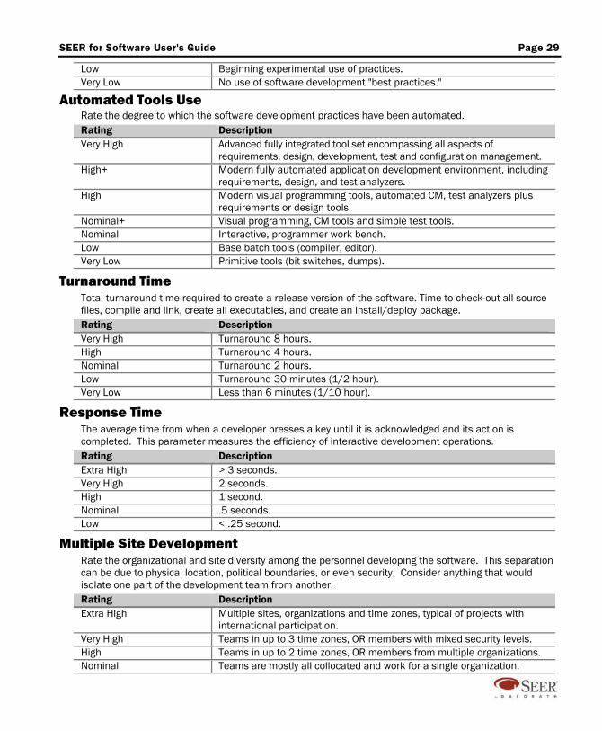
SEER for Software User's Guide Page 29
Low Beginning experimental use of practices. Very Low No use of software development "best practices."
Automated Tools Use Rate the degree to which the software development practices have been automated. Rating Description Very High Advanced fully integrated tool set encompassing all aspects of
requirements, design, development, test and configuration management. High+ Modern fully automated application development environment, including
requirements, design, and test analyzers. High Modern visual programming tools, automated CM, test analyzers plus
requirements or design tools. Nominal+ Visual programming, CM tools and simple test tools. Nominal Interactive, programmer work bench. Low Base batch tools (compiler, editor). Very Low Primitive tools (bit switches, dumps).
Turnaround Time Total turnaround time required to create a release version of the software. Time to check-out all source files, compile and link, create all executables, and create an install/deploy package. Rating Description Very High Turnaround 8 hours. High Turnaround 4 hours. Nominal Turnaround 2 hours. Low Turnaround 30 minutes (1/2 hour). Very Low Less than 6 minutes (1/10 hour).
Response Time The average time from when a developer presses a key until it is acknowledged and its action is completed. This parameter measures the efficiency of interactive development operations. Rating Description Extra High > 3 seconds. Very High 2 seconds. High 1 second. Nominal .5 seconds. Low < .25 second.
Multiple Site Development Rate the organizational and site diversity among the personnel developing the software. This separation can be due to physical location, political boundaries, or even security. Consider anything that would isolate one part of the development team from another. Rating Description Extra High Multiple sites, organizations and time zones, typical of projects with
international participation. Very High Teams in up to 3 time zones, OR members with mixed security levels. High Teams in up to 2 time zones, OR members from multiple organizations. Nominal Teams are mostly all collocated and work for a single organization.
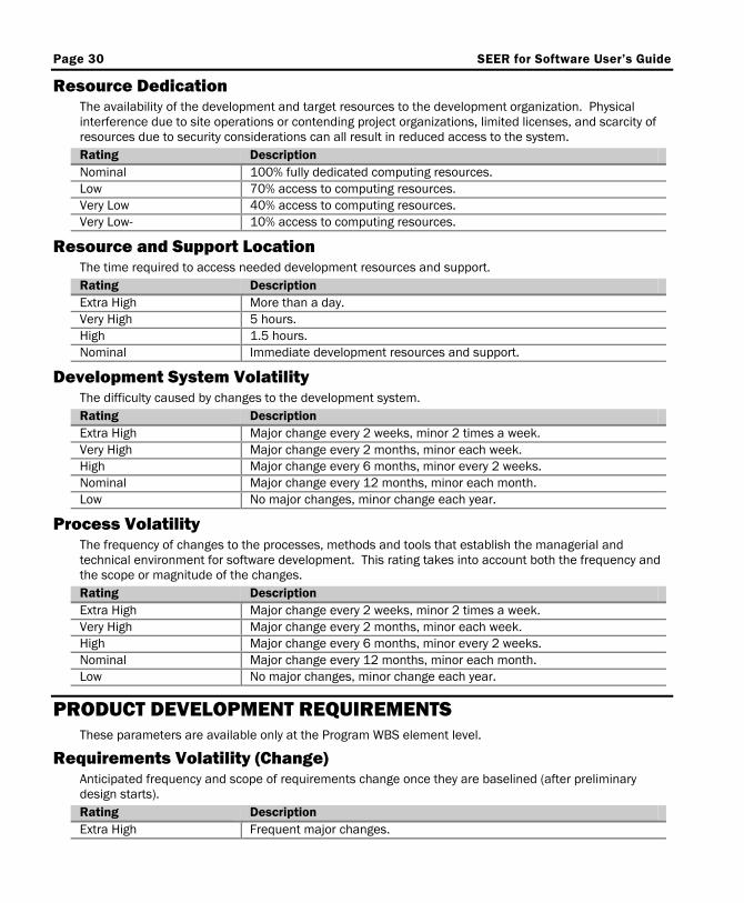
Page 30 SEER for Software User’s Guide
Resource Dedication The availability of the development and target resources to the development organization. Physical interference due to site operations or contending project organizations, limited licenses, and scarcity of resources due to security considerations can all result in reduced access to the system. Rating Description Nominal 100% fully dedicated computing resources. Low 70% access to computing resources. Very Low 40% access to computing resources. Very Low- 10% access to computing resources.
Resource and Support Location The time required to access needed development resources and support. Rating Description Extra High More than a day. Very High 5 hours. High 1.5 hours. Nominal Immediate development resources and support.
Development System Volatility The difficulty caused by changes to the development system. Rating Description Extra High Major change every 2 weeks, minor 2 times a week. Very High Major change every 2 months, minor each week. High Major change every 6 months, minor every 2 weeks. Nominal Major change every 12 months, minor each month. Low No major changes, minor change each year.
Process Volatility The frequency of changes to the processes, methods and tools that establish the managerial and technical environment for software development. This rating takes into account both the frequency and the scope or magnitude of the changes. Rating Description Extra High Major change every 2 weeks, minor 2 times a week. Very High Major change every 2 months, minor each week. High Major change every 6 months, minor every 2 weeks. Nominal Major change every 12 months, minor each month. Low No major changes, minor change each year.
PRODUCT DEVELOPMENT REQUIREMENTS These parameters are available only at the Program WBS element level.
Requirements Volatility (Change) Anticipated frequency and scope of requirements change once they are baselined (after preliminary design starts). Rating Description Extra High Frequent major changes.
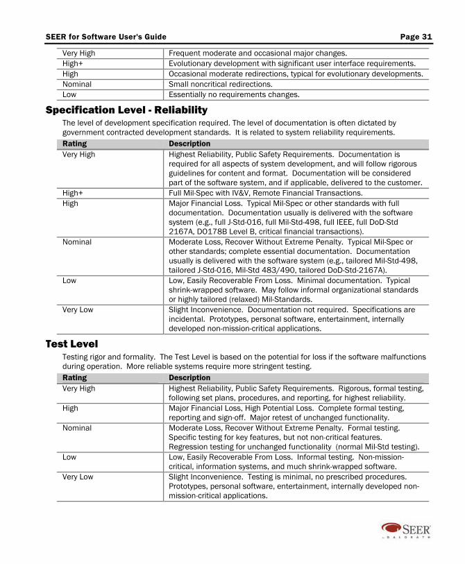
SEER for Software User's Guide Page 31
Very High Frequent moderate and occasional major changes. High+ Evolutionary development with significant user interface requirements. High Occasional moderate redirections, typical for evolutionary developments. Nominal Small noncritical redirections. Low Essentially no requirements changes.
Specification Level - Reliability The level of development specification required. The level of documentation is often dictated by government contracted development standards. It is related to system reliability requirements. Rating Description Very High Highest Reliability, Public Safety Requirements. Documentation is
required for all aspects of system development, and will follow rigorous guidelines for content and format. Documentation will be considered part of the software system, and if applicable, delivered to the customer.
High+ Full Mil-Spec with IV&V, Remote Financial Transactions. High Major Financial Loss. Typical Mil-Spec or other standards with full
documentation. Documentation usually is delivered with the software system (e.g., full J-Std-016, full Mil-Std-498, full IEEE, full DoD-Std 2167A, DO178B Level B, critical financial transactions).
Nominal Moderate Loss, Recover Without Extreme Penalty. Typical Mil-Spec or other standards; complete essential documentation. Documentation usually is delivered with the software system (e.g., tailored Mil-Std-498, tailored J-Std-016, Mil-Std 483/490, tailored DoD-Std-2167A).
Low Low, Easily Recoverable From Loss. Minimal documentation. Typical shrink-wrapped software. May follow informal organizational standards or highly tailored (relaxed) Mil-Standards.
Very Low Slight Inconvenience. Documentation not required. Specifications are incidental. Prototypes, personal software, entertainment, internally developed non-mission-critical applications.
Test Level Testing rigor and formality. The Test Level is based on the potential for loss if the software malfunctions during operation. More reliable systems require more stringent testing. Rating Description Very High Highest Reliability, Public Safety Requirements. Rigorous, formal testing,
following set plans, procedures, and reporting, for highest reliability. High Major Financial Loss, High Potential Loss. Complete formal testing,
reporting and sign-off. Major retest of unchanged functionality. Nominal Moderate Loss, Recover Without Extreme Penalty. Formal testing.
Specific testing for key features, but not non-critical features. Regression testing for unchanged functionality (normal Mil-Std testing).
Low Low, Easily Recoverable From Loss. Informal testing. Non-mission-critical, information systems, and much shrink-wrapped software.
Very Low Slight Inconvenience. Testing is minimal, no prescribed procedures. Prototypes, personal software, entertainment, internally developed non-mission-critical applications.
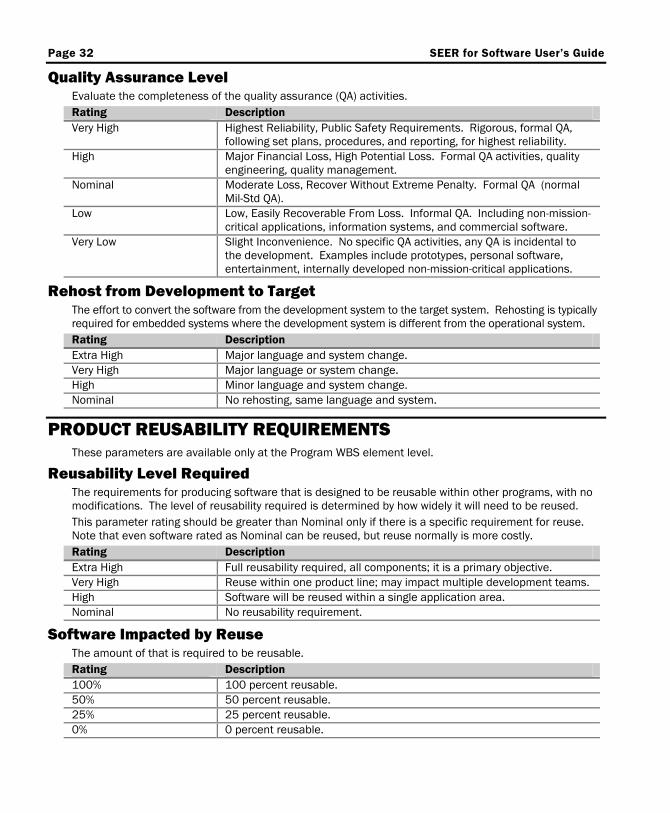
Page 32 SEER for Software User’s Guide
Quality Assurance Level Evaluate the completeness of the quality assurance (QA) activities. Rating Description Very High Highest Reliability, Public Safety Requirements. Rigorous, formal QA,
following set plans, procedures, and reporting, for highest reliability. High Major Financial Loss, High Potential Loss. Formal QA activities, quality
engineering, quality management. Nominal Moderate Loss, Recover Without Extreme Penalty. Formal QA (normal
Mil-Std QA). Low Low, Easily Recoverable From Loss. Informal QA. Including non-mission-
critical applications, information systems, and commercial software. Very Low Slight Inconvenience. No specific QA activities, any QA is incidental to
the development. Examples include prototypes, personal software, entertainment, internally developed non-mission-critical applications.
Rehost from Development to Target The effort to convert the software from the development system to the target system. Rehosting is typically required for embedded systems where the development system is different from the operational system. Rating Description Extra High Major language and system change. Very High Major language or system change. High Minor language and system change. Nominal No rehosting, same language and system.
PRODUCT REUSABILITY REQUIREMENTS These parameters are available only at the Program WBS element level.
Reusability Level Required The requirements for producing software that is designed to be reusable within other programs, with no modifications. The level of reusability required is determined by how widely it will need to be reused. This parameter rating should be greater than Nominal only if there is a specific requirement for reuse. Note that even software rated as Nominal can be reused, but reuse normally is more costly. Rating Description Extra High Full reusability required, all components; it is a primary objective. Very High Reuse within one product line; may impact multiple development teams. High Software will be reused within a single application area. Nominal No reusability requirement.
Software Impacted by Reuse The amount of that is required to be reusable. Rating Description 100% 100 percent reusable. 50% 50 percent reusable. 25% 25 percent reusable. 0% 0 percent reusable.
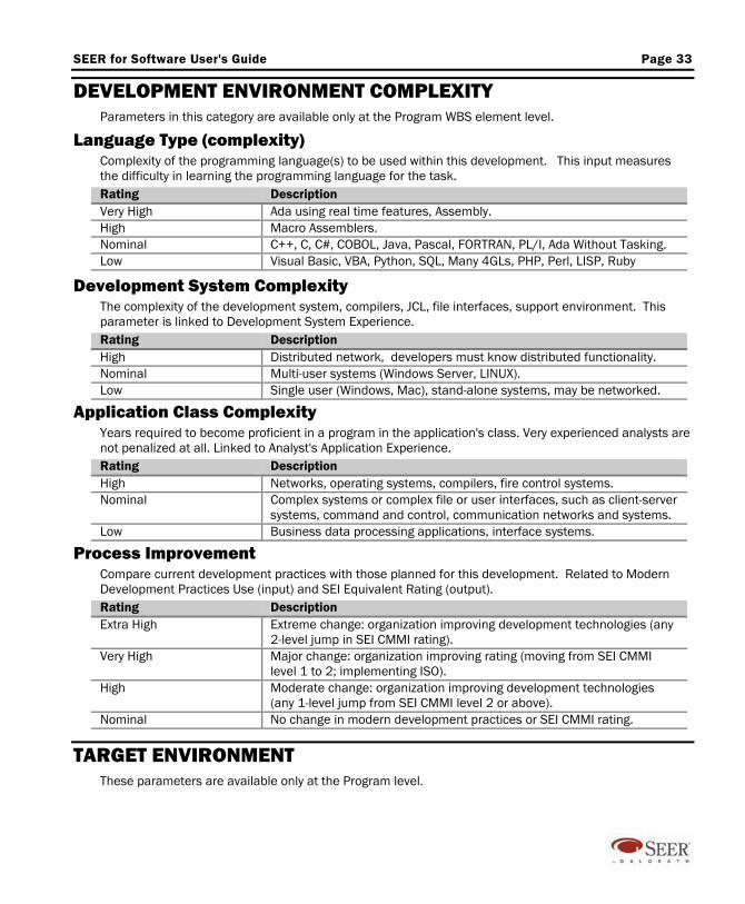
SEER for Software User's Guide Page 33
DEVELOPMENT ENVIRONMENT COMPLEXITY Parameters in this category are available only at the Program WBS element level.
Language Type (complexity) Complexity of the programming language(s) to be used within this development. This input measures the difficulty in learning the programming language for the task. Rating Description Very High Ada using real time features, Assembly. High Macro Assemblers. Nominal C++, C, C#, COBOL, Java, Pascal, FORTRAN, PL/I, Ada Without Tasking. Low Visual Basic, VBA, Python, SQL, Many 4GLs, PHP, Perl, LISP, Ruby
Development System Complexity The complexity of the development system, compilers, JCL, file interfaces, support environment. This parameter is linked to Development System Experience. Rating Description High Distributed network, developers must know distributed functionality. Nominal Multi-user systems (Windows Server, LINUX). Low Single user (Windows, Mac), stand-alone systems, may be networked.
Application Class Complexity Years required to become proficient in a program in the application's class. Very experienced analysts are not penalized at all. Linked to Analyst's Application Experience. Rating Description High Networks, operating systems, compilers, fire control systems. Nominal Complex systems or complex file or user interfaces, such as client-server
systems, command and control, communication networks and systems. Low Business data processing applications, interface systems.
Process Improvement Compare current development practices with those planned for this development. Related to Modern Development Practices Use (input) and SEI Equivalent Rating (output). Rating Description Extra High Extreme change: organization improving development technologies (any
2-level jump in SEI CMMI rating). Very High Major change: organization improving rating (moving from SEI CMMI
level 1 to 2; implementing ISO). High Moderate change: organization improving development technologies
(any 1-level jump from SEI CMMI level 2 or above). Nominal No change in modern development practices or SEI CMMI rating.
TARGET ENVIRONMENT These parameters are available only at the Program level.
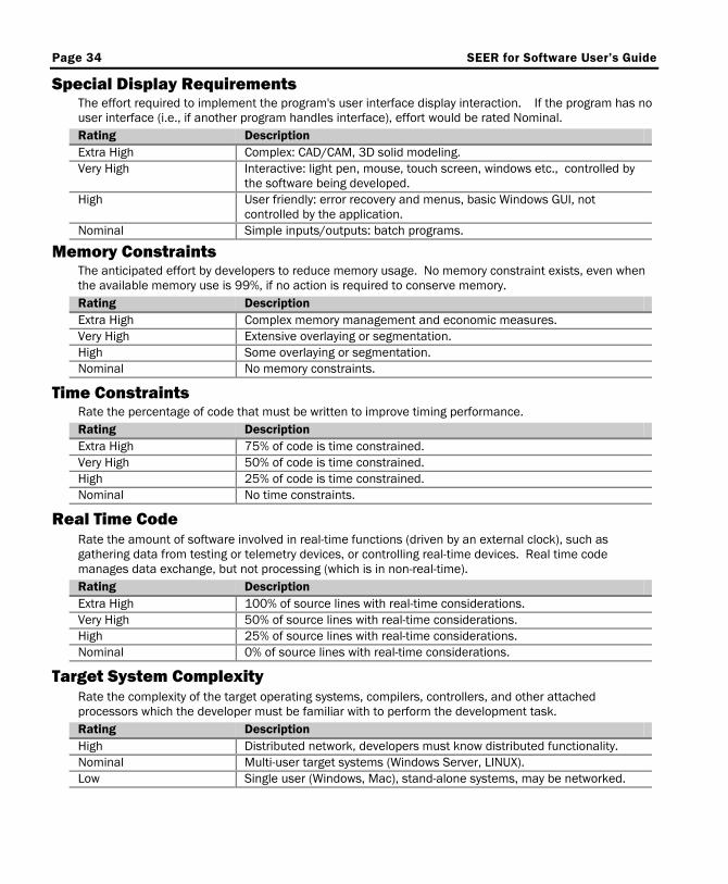
Page 34 SEER for Software User’s Guide
Special Display Requirements The effort required to implement the program's user interface display interaction. If the program has no user interface (i.e., if another program handles interface), effort would be rated Nominal. Rating Description Extra High Complex: CAD/CAM, 3D solid modeling. Very High Interactive: light pen, mouse, touch screen, windows etc., controlled by
the software being developed. High User friendly: error recovery and menus, basic Windows GUI, not
controlled by the application. Nominal Simple inputs/outputs: batch programs.
Memory Constraints The anticipated effort by developers to reduce memory usage. No memory constraint exists, even when the available memory use is 99%, if no action is required to conserve memory. Rating Description Extra High Complex memory management and economic measures. Very High Extensive overlaying or segmentation. High Some overlaying or segmentation. Nominal No memory constraints.
Time Constraints Rate the percentage of code that must be written to improve timing performance. Rating Description Extra High 75% of code is time constrained. Very High 50% of code is time constrained. High 25% of code is time constrained. Nominal No time constraints.
Real Time Code Rate the amount of software involved in real-time functions (driven by an external clock), such as gathering data from testing or telemetry devices, or controlling real-time devices. Real time code manages data exchange, but not processing (which is in non-real-time). Rating Description Extra High 100% of source lines with real-time considerations. Very High 50% of source lines with real-time considerations. High 25% of source lines with real-time considerations. Nominal 0% of source lines with real-time considerations.
Target System Complexity Rate the complexity of the target operating systems, compilers, controllers, and other attached processors which the developer must be familiar with to perform the development task. Rating Description High Distributed network, developers must know distributed functionality. Nominal Multi-user target systems (Windows Server, LINUX). Low Single user (Windows, Mac), stand-alone systems, may be networked.

SEER for Software User's Guide Page 35
Target System Volatility Determine the difficulty caused by changes to the target system. These may be changes in the program editors, compilers, or other tools, in the command languages, or in the target hardware. Rating Description Extra High Major change every 2 weeks, minor 2 times a week. Very High Major change every 2 months, minor each week. High Major change every 6 months, minor every 2 weeks Nominal Major change every 12 months, minor each month. Low No major changes, minor change each year.
Security Requirements Rate development impact of security requirements for the delivered target system. Rate special work to be performed during this development only. If security requirements will be met by the operating system, by other software, or by a physically secure environment (behind locked doors), select Nominal. This parameter can also be used to rate safety critical requirements that need to be addressed by the development project. Security and safety classifications are referenced in the rating scale. Rating Description Extra Hi+ Class A1: Security formally verified by mathematical proof (very rare).
DO178B — Level A: Software whose anomalous behavior, as shown by the system safety assessment process, would cause or contribute to a failure of system function resulting in a catastrophic failure of the aircraft.
Extra Hi- Common Criteria — EAL 7: Formally Verified Design and Tested. The formal model is supplemented by a formal presentation of the functional specification and high level design showing correspondence.
Very High+ DO178B — Level B: Software whose anomalous behavior, as shown by the system safety assessment process, would cause or contribute to a failure of system function resulting in a hazardous/severe-major failure condition for the aircraft. Common Criteria — EAL 6: Semiformally Verified Design and Tested.
Very High Class B3: System excludes code not essential to security enforcement. Audit capability is strengthened. System almost completely resistant to penetration. Common Criteria — EAL 5: Semiformally Designed and Tested.
Very High- DO178B — Level C: Software whose anomalous behavior, as shown by the system safety assessment process, would cause or contribute to a failure of system function resulting in a major failure condition for the aircraft.
High+ Class B2: System segregated into protection-critical and non-protection-critical elements. Overall system resistant to penetration (Critical Financial Processing). Common Criteria — EAL 4: Methodically Designed, Tested, and Reviewed.
High Class B1: In addition to C2, data labeling and mandatory access control are present. Flaws identified by testing are removed (Classified or Financial Processing). Common Criteria — EAL 3: Methodically Tested and Checked.
High- Class C2: Users individually accountable via logon operations, auditing of security relevant events and resource isolation. (Typical multi-user operating system such as OpenVMS).
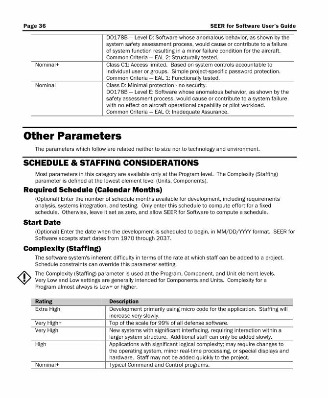
Page 36 SEER for Software User’s Guide
DO178B — Level D: Software whose anomalous behavior, as shown by the system safety assessment process, would cause or contribute to a failure of system function resulting in a minor failure condition for the aircraft. Common Criteria — EAL 2: Structurally tested.
Nominal+ Class C1: Access limited. Based on system controls accountable to individual user or groups. Simple project-specific password protection. Common Criteria — EAL 1: Functionally tested.
Nominal Class D: Minimal protection - no security. DO178B — Level E: Software whose anomalous behavior, as shown by the safety assessment process, would cause or contribute to a system failure with no effect on aircraft operational capability or pilot workload. Common Criteria — EAL 0: Inadequate Assurance.
Other Parameters The parameters which follow are related neither to size nor to technology and environment.
SCHEDULE & STAFFING CONSIDERATIONS Most parameters in this category are available only at the Program level. The Complexity (Staffing) parameter is defined at the lowest element level (Units, Components).
Required Schedule (Calendar Months) (Optional) Enter the number of schedule months available for development, including requirements analysis, systems integration, and testing. Only enter this schedule to compute effort for a fixed schedule. Otherwise, leave it set as zero, and allow SEER for Software to compute a schedule.
Start Date (Optional) Enter the date when the development is scheduled to begin, in MM/DD/YYYY format. SEER for Software accepts start dates from 1970 through 2037.
Complexity (Staffing) The software system's inherent difficulty in terms of the rate at which staff can be added to a project. Schedule constraints can override this parameter setting.
The Complexity (Staffing) parameter is used at the Program, Component, and Unit element levels. Very Low and Low settings are generally intended for Components and Units. Complexity for a Program almost always is Low+ or higher. Rating Description Extra High Development primarily using micro code for the application. Staffing will
increase very slowly. Very High+ Top of the scale for 99% of all defense software. Very High New systems with significant interfacing, requiring interaction within a
larger system structure. Additional staff can only be added slowly. High Applications with significant logical complexity; may require changes to
the operating system, minor real-time processing, or special displays and hardware. Staff may not be added quickly to the project.
Nominal+ Typical Command and Control programs.
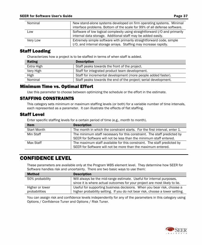
SEER for Software User's Guide Page 37
Nominal New stand-alone systems developed on firm operating systems. Minimal interface problems. Bottom of the scale for 99% of all defense software.
Low Software of low logical complexity using straightforward I/O and primarily internal data storage. Additional staff may be added easily.
Very Low Extremely simple software with primarily straightforward code, simple I/O, and internal storage arrays. Staffing may increase rapidly.
Staff Loading Characterizes how a project is to be staffed in terms of when staff is added. Rating Description Extra High Staff peaks towards the front of the project. Very High Staff for integrated product team development. High Staff for incremental development (more people added faster). Nominal Staff peaks towards the end of the project; serial development.
Minimum Time vs. Optimal Effort Use this parameter to choose between optimizing the schedule or the effort in the estimate.
STAFFING CONSTRAINTS This category sets minimum or maximum staffing levels (or both) for a variable number of time intervals, each represented as a parameter. It can illustrate the effects of flat staffing.
Staff Level Enter specific staffing levels for a certain period of time (e.g., month to month). Item Description Start Month The month in which the constraint starts. For the first interval, enter 1. Min Staff The minimum staff necessary for this constraint. The staff predicted by
SEER for Software will not be less than the minimum staff entered. Max Staff The maximum staff available for this constraint. The staff predicted by
SEER for Software will not be more than the maximum entered.
CONFIDENCE LEVEL These parameters are available only at the Program WBS element level. They determine how SEER for Software handles risk and uncertainty. There are two basic ways to use them: Method Description 50% probability Will always be the mid-range estimate. Useful for internal purposes,
since it is where actual outcomes for your project are most likely to lie. Higher or lower probabilities
Useful for supporting business decisions. When you bear risk, choose a higher probability setting. If you do not bear risk, choose a lower setting.
You can assign risk and confidence levels independently for any of the parameters in this category using Options / Confidence Tuner and Options / Risk Tuner.
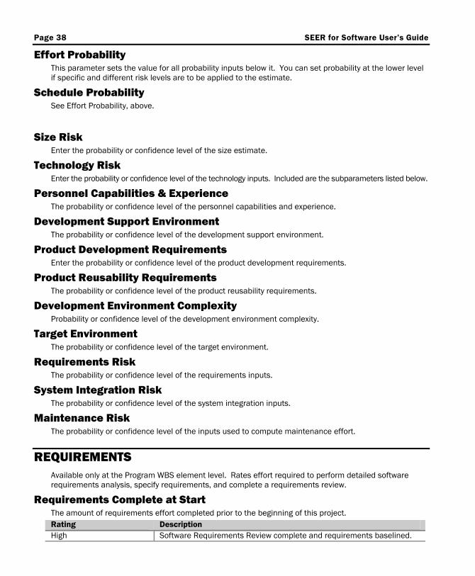
Page 38 SEER for Software User’s Guide
Effort Probability This parameter sets the value for all probability inputs below it. You can set probability at the lower level if specific and different risk levels are to be applied to the estimate.
Schedule Probability See Effort Probability, above.
Size Risk
Enter the probability or confidence level of the size estimate.
Technology Risk Enter the probability or confidence level of the technology inputs. Included are the subparameters listed below.
Personnel Capabilities & Experience The probability or confidence level of the personnel capabilities and experience.
Development Support Environment The probability or confidence level of the development support environment.
Product Development Requirements Enter the probability or confidence level of the product development requirements.
Product Reusability Requirements The probability or confidence level of the product reusability requirements.
Development Environment Complexity Probability or confidence level of the development environment complexity.
Target Environment The probability or confidence level of the target environment.
Requirements Risk The probability or confidence level of the requirements inputs.
System Integration Risk The probability or confidence level of the system integration inputs.
Maintenance Risk The probability or confidence level of the inputs used to compute maintenance effort.
REQUIREMENTS Available only at the Program WBS element level. Rates effort required to perform detailed software requirements analysis, specify requirements, and complete a requirements review.
Requirements Complete at Start The amount of requirements effort completed prior to the beginning of this project. Rating Description High Software Requirements Review complete and requirements baselined.
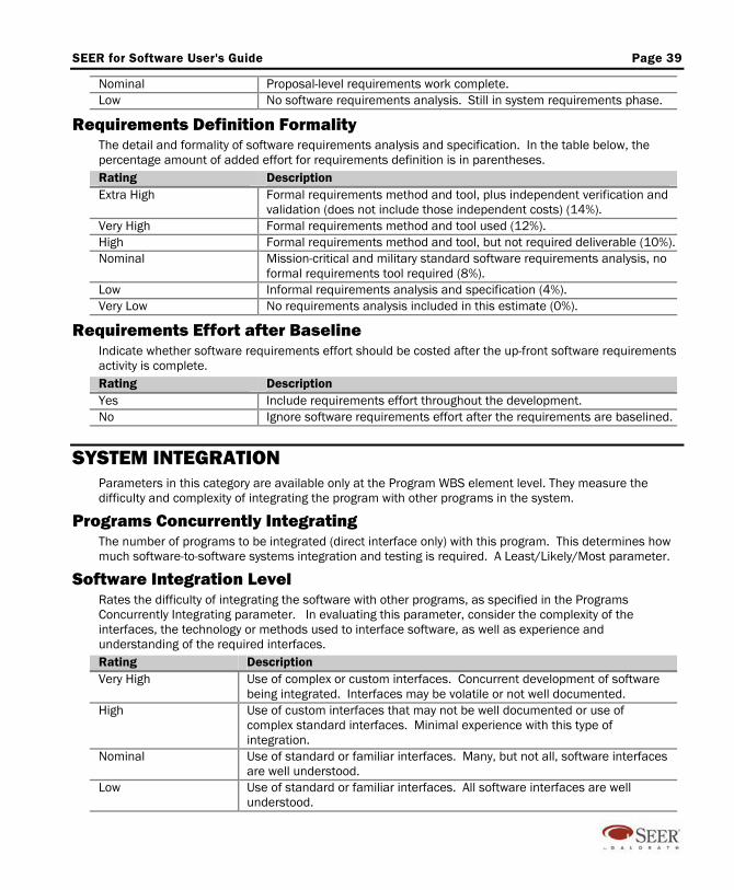
SEER for Software User's Guide Page 39
Nominal Proposal-level requirements work complete. Low No software requirements analysis. Still in system requirements phase.
Requirements Definition Formality The detail and formality of software requirements analysis and specification. In the table below, the percentage amount of added effort for requirements definition is in parentheses. Rating Description Extra High Formal requirements method and tool, plus independent verification and
validation (does not include those independent costs) (14%). Very High Formal requirements method and tool used (12%). High Formal requirements method and tool, but not required deliverable (10%). Nominal Mission-critical and military standard software requirements analysis, no
formal requirements tool required (8%). Low Informal requirements analysis and specification (4%). Very Low No requirements analysis included in this estimate (0%).
Requirements Effort after Baseline Indicate whether software requirements effort should be costed after the up-front software requirements activity is complete. Rating Description Yes Include requirements effort throughout the development. No Ignore software requirements effort after the requirements are baselined.
SYSTEM INTEGRATION Parameters in this category are available only at the Program WBS element level. They measure the difficulty and complexity of integrating the program with other programs in the system.
Programs Concurrently Integrating The number of programs to be integrated (direct interface only) with this program. This determines how much software-to-software systems integration and testing is required. A Least/Likely/Most parameter.
Software Integration Level Rates the difficulty of integrating the software with other programs, as specified in the Programs Concurrently Integrating parameter. In evaluating this parameter, consider the complexity of the interfaces, the technology or methods used to interface software, as well as experience and understanding of the required interfaces. Rating Description Very High Use of complex or custom interfaces. Concurrent development of software
being integrated. Interfaces may be volatile or not well documented. High Use of custom interfaces that may not be well documented or use of
complex standard interfaces. Minimal experience with this type of integration.
Nominal Use of standard or familiar interfaces. Many, but not all, software interfaces are well understood.
Low Use of standard or familiar interfaces. All software interfaces are well understood.
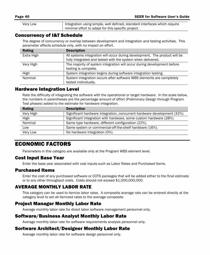
Page 40 SEER for Software User’s Guide
Very Low Integration using simple, well defined, standard interfaces which require minimal effort to adapt for this specific project.
Concurrency of I&T Schedule The degree of concurrency or overlap between development and integration and testing activities. This parameter affects schedule only, with no impact on effort. Rating Description Extra High All systems integration will occur during development. The product will be
fully integrated and tested with the system when delivered. Very High The majority of system integration will occur during development before
testing is complete. High System integration begins during software integration testing. Nominal System integration occurs after software WBS elements are completely
tested individually.
Hardware Integration Level Rate the difficulty of integrating the software with the operational or target hardware. In the scale below, the numbers in parentheses are the percentage amount of effort (Preliminary Design through Program Test phases) added to the estimate for hardware integration. Rating Description Very High Significant hardware integration, concurrent hardware development (32%). High Significant integration with hardware, some custom hardware (28%). Nominal Same type hardware, different configuration (22%). Low Same system or commercial-off-the-shelf hardware (16%). Very Low No hardware integration (0%).
ECONOMIC FACTORS Parameters in this category are available only at the Program WBS element level.
Cost Input Base Year Enter the base year associated with cost inputs such as Labor Rates and Purchased Items.
Purchased Items Enter the cost of any purchased software or COTS packages that will be added either to the final estimate or to any other throughput costs. Costs should not exceed $1,000,000,000.
AVERAGE MONTHLY LABOR RATE This category can be used to itemize labor rates. A composite average rate can be entered directly at the category level to set all itemized rates to the average composite.
Project Manager Monthly Labor Rate Average monthly labor rate for direct labor software management personnel only.
Software/Business Analyst Monthly Labor Rate Average monthly labor rate for software requirements analysis personnel only.
Sortware Architect/Designer Monthly Labor Rate Average monthly labor rate for software design personnel only.
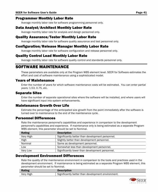
SEER for Software User's Guide Page 41
Programmer Monthly Labor Rate Average monthly labor rate for software programming personnel only.
Data Analyst/Architect Monthly Labor Rate Average monthly labor rate for analysis and design personnel only.
Quality Assurance/Tester Monthly Labor Rate Average monthly labor rate for software quality assurance and test personnel only.
Configuration/Release Manager Monthly Labor Rate Average monthly labor rate for software configuration and release personnel only.
Quality Control Lead Monthly Labor Rate Average monthly labor rate for software quality control and standards personnel only.
SOFTWARE MAINTENANCE These parameters are available only at the Program WBS element level. SEER for Software estimates the effort and cost of software maintenance using a sophisticated model.
Years of Maintenance Enter the number of years for which software maintenance costs will be estimated. You can enter partial years: 1.53, 0.75, etc.
Separate Sites Enter the number of separate operational sites where the software will be installed, and where users will have significant input into system enhancements.
Maintenance Growth Over Life Estimate the percentage of the anticipated size growth from the point immediately after the software is turned over to maintenance to the end of the maintenance cycle.
Personnel Differences Rate the maintenance personnel's capabilities and experience in comparison to the development personnel's capabilities and experience. If maintenance only is being estimated as a separate Program WBS element, this parameter should be set to Nominal. Rating Description Very High Significantly better than development personnel. High Slightly better than development personnel. Nominal Same as development personnel. Low Somewhat less than development personnel. Very Low Significantly lower than development personnel.
Development Environment Differences Rate the quality of the maintenance environment in comparison to the tools and practices used in the development environment. If maintenance is being estimated as a separate Program WBS element, this parameter should be set to Nominal. Rating Description Very High Significantly better than development environment.

Page 42 SEER for Software User’s Guide
High Slightly better than development environment. Nominal Same as development environment. Low Somewhat worse than development environment. Very Low Significantly worse than development environment.
Annual Change Rate Estimate the average percentage of the software impacted by software maintenance and sustaining engineering per year.
Maintenance Level (Rigor) The thoroughness with which maintenance activities will be performed. Rating Description Very High+ Used for compatibility with projects created with SEER-SEM version 3
and earlier, which will have a Very High+ rating when loaded into SEER for Software.
Very High Thorough maintenance, including regular documentation updates. Maintenance is well planned, with frequent reviews of priorities. Dedicated maintenance staff. Software will not degenerate over time.
High Complete maintenance including maintenance planning and priority review. Software documentation is updated on a semiregular basis. Software will not degenerate over time.
Nominal Average maintenance activity. Short-term planning and prioritization. Documentation is updated less than once a year. Software will become less useful over time.
Low Basic maintenance, mostly reactive to emergencies. No planning. Documentation is updated only with page and addenda changes. Software will degenerate over time.
Very Low Bare bones maintenance. Nondedicated team doing emergency fixes. Little to no documentation update. Software will degenerate rapidly.
Minimum Maintenance Staff (Optional) The minimum number of personnel who will be assigned to maintain the software.
Maximum Maintenance Staff (Optional) The maximum number of personnel who will be assigned to maintain the software.
Maintenance Monthly Labor Rate The average monthly labor rate for maintenance personnel.
Additional Annual Maintenance Cost Enter any annual throughput costs for maintenance.
Maintenance Start Date The date on which maintenance will begin. If no date is entered, maintenance will begin when operational evaluation and test is completed. Use a MM/DD/YYYY format.
Percent To Be Maintained Estimate the percentage of the total that will be maintained.
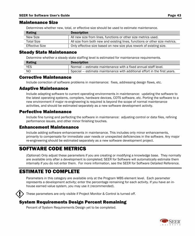
SEER for Software User's Guide Page 43
Maintenance Size Determines whether new, total, or effective size should be used to estimate maintenance. Rating Description New Size All new size from lines, functions or other size metrics used. Total Size All size from both new and existing lines, functions or other size metrics. Effective Size Only effective size based on new size plus rework of existing size.
Steady State Maintenance Determine whether a steady state staffing level is estimated for maintenance requirements. Rating Description YES Normal — estimate maintenance with a fixed annual staff level. NO Special — estimate maintenance with additional effort in the first years.
Corrective Maintenance Include correction of software problems in maintenance: fixes, addressing design flaws, etc.
Adaptive Maintenance Include adapting software to current operating environments in maintenance: updating the software to the latest operating systems, compilers, hardware devices, COTS software, etc. Porting the software to a new environment if major re-engineering is required is beyond the scope of normal maintenance activities, and should be estimated separately as a new software development activity.
Perfective Maintenance Include fine tuning and perfecting the software in maintenance: adjusting control or data files, refining performance issues, and other minor finishing touches.
Enhancement Maintenance Include adding software enhancements in maintenance. This includes only minor enhancements, primarily to compensate for immediate user needs or unexpected deficiencies in the software. Any major re-engineering should be estimated separately as a new software development project.
SOFTWARE CODE METRICS (Optional) Only adjust these parameters if you are creating or modifying a knowledge base. They normally are available only after a development is completed; SEER for Software will automatically estimate them internally if you do not enter them. For more information, see the SEER for Software Detailed Reference.
ESTIMATE TO COMPLETE Parameters in this category are available only at the Program WBS element level. Each parameter represents a development activity; enter the percentage remaining for each activity. If you have an in-house earned value system, you may use it (recommended).
These parameters are only visible if Project Monitor & Control is turned off.
System Requirements Design Percent Remaining Percent of System Requirements Design yet to be completed.
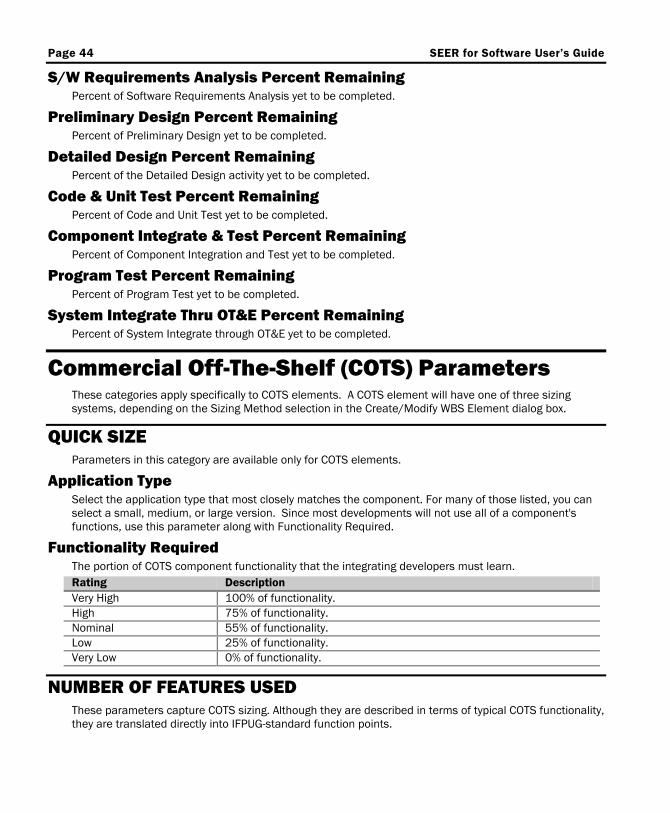
Page 44 SEER for Software User’s Guide
S/W Requirements Analysis Percent Remaining Percent of Software Requirements Analysis yet to be completed.
Preliminary Design Percent Remaining Percent of Preliminary Design yet to be completed.
Detailed Design Percent Remaining Percent of the Detailed Design activity yet to be completed.
Code & Unit Test Percent Remaining Percent of Code and Unit Test yet to be completed.
Component Integrate & Test Percent Remaining Percent of Component Integration and Test yet to be completed.
Program Test Percent Remaining Percent of Program Test yet to be completed.
System Integrate Thru OT&E Percent Remaining Percent of System Integrate through OT&E yet to be completed.
Commercial Off-The-Shelf (COTS) Parameters These categories apply specifically to COTS elements. A COTS element will have one of three sizing systems, depending on the Sizing Method selection in the Create/Modify WBS Element dialog box.
QUICK SIZE Parameters in this category are available only for COTS elements.
Application Type Select the application type that most closely matches the component. For many of those listed, you can select a small, medium, or large version. Since most developments will not use all of a component's functions, use this parameter along with Functionality Required.
Functionality Required The portion of COTS component functionality that the integrating developers must learn. Rating Description Very High 100% of functionality. High 75% of functionality. Nominal 55% of functionality. Low 25% of functionality. Very Low 0% of functionality.
NUMBER OF FEATURES USED These parameters capture COTS sizing. Although they are described in terms of typical COTS functionality, they are translated directly into IFPUG-standard function points.

SEER for Software User's Guide Page 45
Unique Functions Number of unique functions that are being used or must be understood to integrate the component. Functions may reside in APIs, program libraries, etc. A function may pass data, receive data, or both pass and receive data. Count the least, likely, and highest possible number of unique functions being referenced and used.
Data Tables Referenced The least, likely, and highest possible number of unique data tables referenced (but not changed). Unique data tables include configuration files, databases, and external data structures. Count a single database with several closely related tables once only, unless they are sufficiently different.
Data Tables Configured The least, likely, and highest possible number of data tables that must be configured, changed or created to integrate the component, including configuration files, databases, and external data structures. Count a single database with several closely related tables only once, unless they are sufficiently different. If a table is being used to learn table creation or configuration only, do not count it.
OBJECT SIZING Parameters in this category are defined only for COTS elements. See Sizing in SEER for Software / Function Counting, below.
Input Methods Count the least, likely, and highest possible number of External Inputs used as methods in all object classes. Use the standard IFPUG definition for an External Input.
Output Methods Count the least, likely, and highest possible number of External Outputs used as methods in all object classes. Use the standard IFPUG definition for an External Output.
Inquiry Methods Count the least, likely, and highest possible number of External Inquiries used as methods in all object classes. Use the standard IFPUG definition for an External Inquiry.
External Class Count the least, likely, and highest possible number of object classes used outside the application boundary. They are treated as IFPUG-standard External Logical Files.
Internal Class Count the least, likely, and highest possible number of object classes used inside the application boundary. They are treated as IFPUG-standard Internal Logical Files.
OFF-THE-SHELF PRODUCT CHARACTERISTICS Parameters in this category are defined only for COTS elements.
Component Type Select the description that best fits the type of component from the integrator's point of view. Consider the packaging, the manner in which it is integrated, and the level of code detail that a programmer sees when implementing this component.
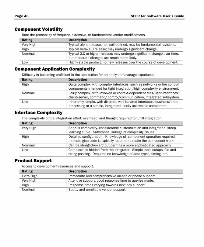
Page 46 SEER for Software User’s Guide
Component Volatility Rate the probability of frequent, extensive, or fundamental vendor modifications. Rating Description Very High Typical alpha release; not well defined, may be fundamental revisions. High Typical beta/1.0 release; may undergo significant change. Nominal Typical 2.0 or higher release; may undergo significant change over time,
but moderate changes are much more likely. Low Highly stable product; no new releases over the course of development.
Component Application Complexity Difficulty in becoming proficient in the application for an analyst of average experience. Rating Description High Quite complex, with complex interfaces, such as networks or fire control;
components intended for tight integration/high complexity environment. Nominal Fairly complex, with involved or context-dependent files/user interfaces;
client/server, command/ control/communication, integrated subsystem. Low Inherently simple, with discrete, well-isolated interfaces; business/data
processing or a simple, integrated, easily accessible component.
Interface Complexity The complexity of the integration effort, overhead, and thought required to fulfill integration. Rating Description Very High Serious complexity, considerable customization and integration, steep
learning curve. Substantial linkage of complexity issues. High Detailed configuration. Knowledge of component operation required.
Intimate glue code is typically required to make the component work. Nominal Can be straightforward but permits a more sophisticated approach. Low Complexities hidden from the integrator. Simple table setups, file and
string passing. Requires no knowledge of data types, timing, etc.
Product Support Access to development resources and support. Rating Description Extra High Immediate and comprehensive on-site or phone support. Very High Attentive support, good response time to queries made. High Response times varying towards next day support. Nominal Spotty and unreliable vendor support.
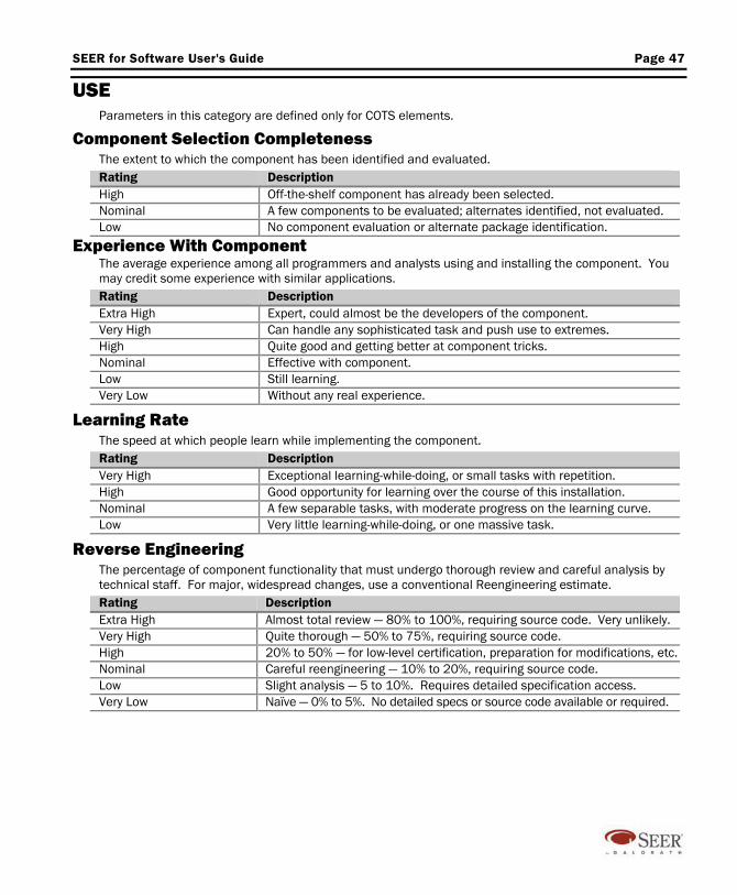
SEER for Software User's Guide Page 47
USE Parameters in this category are defined only for COTS elements.
Component Selection Completeness The extent to which the component has been identified and evaluated. Rating Description High Off-the-shelf component has already been selected. Nominal A few components to be evaluated; alternates identified, not evaluated. Low No component evaluation or alternate package identification.
Experience With Component The average experience among all programmers and analysts using and installing the component. You may credit some experience with similar applications. Rating Description Extra High Expert, could almost be the developers of the component. Very High Can handle any sophisticated task and push use to extremes. High Quite good and getting better at component tricks. Nominal Effective with component. Low Still learning. Very Low Without any real experience.
Learning Rate The speed at which people learn while implementing the component. Rating Description Very High Exceptional learning-while-doing, or small tasks with repetition. High Good opportunity for learning over the course of this installation. Nominal A few separable tasks, with moderate progress on the learning curve. Low Very little learning-while-doing, or one massive task.
Reverse Engineering The percentage of component functionality that must undergo thorough review and careful analysis by technical staff. For major, widespread changes, use a conventional Reengineering estimate. Rating Description Extra High Almost total review — 80% to 100%, requiring source code. Very unlikely. Very High Quite thorough — 50% to 75%, requiring source code. High 20% to 50% — for low-level certification, preparation for modifications, etc. Nominal Careful reengineering — 10% to 20%, requiring source code. Low Slight analysis — 5 to 10%. Requires detailed specification access. Very Low Naïve — 0% to 5%. No detailed specs or source code available or required.
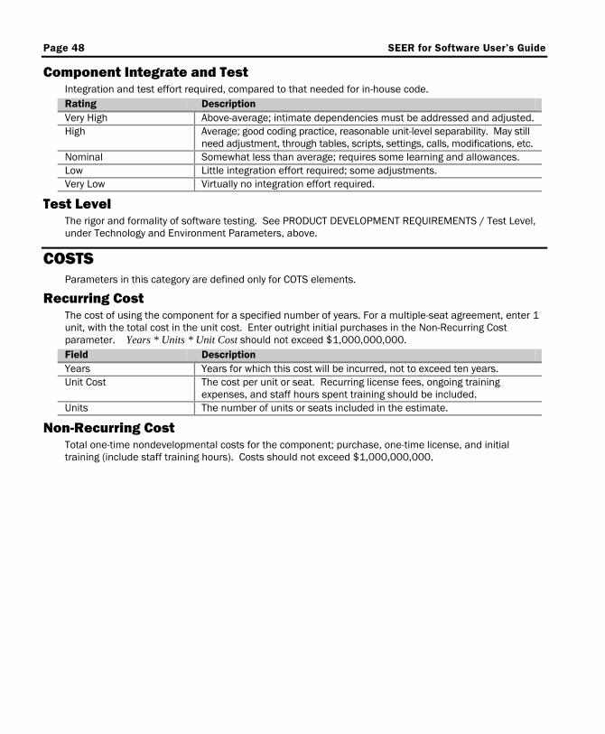
Page 48 SEER for Software User’s Guide
Component Integrate and Test Integration and test effort required, compared to that needed for in-house code. Rating Description Very High Above-average; intimate dependencies must be addressed and adjusted. High Average; good coding practice, reasonable unit-level separability. May still
need adjustment, through tables, scripts, settings, calls, modifications, etc. Nominal Somewhat less than average; requires some learning and allowances. Low Little integration effort required; some adjustments. Very Low Virtually no integration effort required.
Test Level The rigor and formality of software testing. See PRODUCT DEVELOPMENT REQUIREMENTS / Test Level, under Technology and Environment Parameters, above.
COSTS Parameters in this category are defined only for COTS elements.
Recurring Cost The cost of using the component for a specified number of years. For a multiple-seat agreement, enter 1 unit, with the total cost in the unit cost. Enter outright initial purchases in the Non-Recurring Cost parameter. Years * Units * Unit Cost should not exceed $1,000,000,000. Field Description Years Years for which this cost will be incurred, not to exceed ten years. Unit Cost The cost per unit or seat. Recurring license fees, ongoing training
expenses, and staff hours spent training should be included. Units The number of units or seats included in the estimate.
Non-Recurring Cost Total one-time nondevelopmental costs for the component; purchase, one-time license, and initial training (include staff training hours). Costs should not exceed $1,000,000,000.

SEER for Software User's Guide Page 49
SEER for Software Parameter Sensitivities The following chart illustrates the technology and environment input parameter values, and their relative total impacts on cost and effort. Sensitivity is indicated here for individual parameters only. Category level parameters (in capital letters) represent groupings of related parameters; sensitivity is not evaluated at the category level. (In the Parameter View, category parameters are indicated with a plus symbol, "+.")
Parameters’ Relative Impact on Cost and Effort

Page 50 SEER for Software User’s Guide
Removing Requirements and System Integration from an Estimate
You can easily exclude requirements and/or system integration from your estimate by disabling the parameters listed below.
Requirements To create an estimate without including requirements, disable the following parameter: Parameter Action Requirements Definition Formality
Set all three sliders to VLo (Very Low — No requirements analysis included in this estimate.
System Integration To create an estimate without including integration and testing, disable the following parameters: Parameter Action Programs Concurrently Integrating
Enter 0 (Nominal), no software integration.
Hardware Integration Level Set all three sliders to VLo (Very Low — No hardware integration).
Sizing in SEER for Software SEER for Software can estimate size using function points, source lines of code, customizable proxies, or object-oriented sizing; it can also estimate off-the-shelf (COTS) software size.
Source Lines of Code (Classic) This metric is listed in the SEER for Software Parameter window as LINES (Classic). A source line of code (SLOC) is a noncomment software source instruction as defined below. Count only the executable portions of completed, delivered software.
Source Lines Checklist For each logical line of code: Include Executable lines.
Nonexecutable declarations and compiler directives. Exclude Comments, continuation lines, banners, blank lines, instantiated SLOC, and spacers.
Look at the means by which a line was produced: Include Manually programmed lines.
Lines developed for use as an input to a Source Code Generator. Lines converted with code translators (as preexisting lines, with rework percentages). Copied, reused, or modified lines of code. Entered as preexisting Lines of Code. Maintenance estimates only: Source Code Generator output.
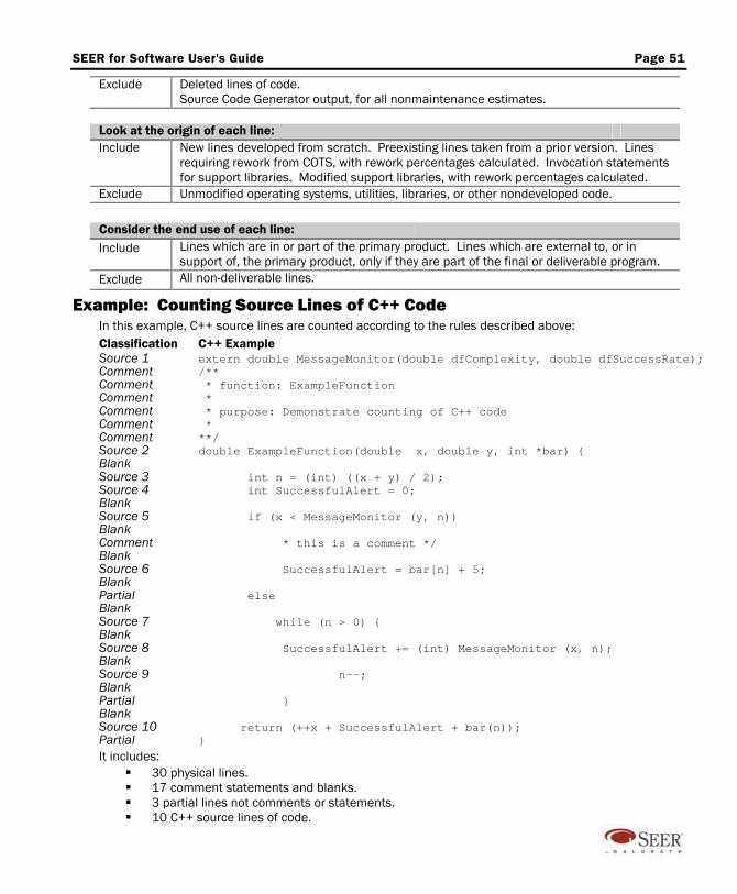
SEER for Software User's Guide Page 51
Exclude Deleted lines of code. Source Code Generator output, for all nonmaintenance estimates.
Look at the origin of each line: Include New lines developed from scratch. Preexisting lines taken from a prior version. Lines
requiring rework from COTS, with rework percentages calculated. Invocation statements for support libraries. Modified support libraries, with rework percentages calculated.
Exclude Unmodified operating systems, utilities, libraries, or other nondeveloped code.
Consider the end use of each line: Include Lines which are in or part of the primary product. Lines which are external to, or in
support of, the primary product, only if they are part of the final or deliverable program. Exclude All non-deliverable lines.
Example: Counting Source Lines of C++ Code In this example, C++ source lines are counted according to the rules described above: Classification C++ Example Source 1 extern double MessageMonitor(double dfComplexity, double dfSuccessRate); Comment /** Comment * function: ExampleFunction Comment * Comment * purpose: Demonstrate counting of C++ code Comment * Comment **/ Source 2 double ExampleFunction(double x, double y, int *bar) { Blank Source 3 int n = (int) ((x + y) / 2); Source 4 int SuccessfulAlert = 0; Blank Source 5 if (x < MessageMonitor (y, n)) Blank Comment * this is a comment */ Blank Source 6 SuccessfulAlert = bar[n] + 5; Blank Partial else Blank Source 7 while (n > 0) { Blank Source 8 SuccessfulAlert += (int) MessageMonitor (x, n); Blank Source 9 n--; Blank Partial } Blank Source 10 return (++x + SuccessfulAlert + bar(n)); Partial } It includes:
30 physical lines. 17 comment statements and blanks. 3 partial lines not comments or statements. 10 C++ source lines of code.
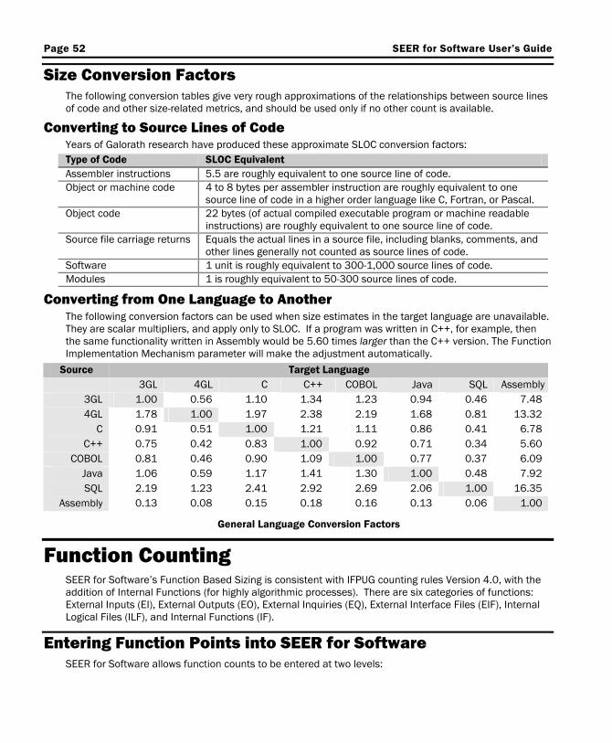
Page 52 SEER for Software User’s Guide
Size Conversion Factors The following conversion tables give very rough approximations of the relationships between source lines of code and other size-related metrics, and should be used only if no other count is available.
Converting to Source Lines of Code Years of Galorath research have produced these approximate SLOC conversion factors: Type of Code SLOC Equivalent Assembler instructions 5.5 are roughly equivalent to one source line of code. Object or machine code 4 to 8 bytes per assembler instruction are roughly equivalent to one
source line of code in a higher order language like C, Fortran, or Pascal. Object code 22 bytes (of actual compiled executable program or machine readable
instructions) are roughly equivalent to one source line of code. Source file carriage returns Equals the actual lines in a source file, including blanks, comments, and
other lines generally not counted as source lines of code. Software 1 unit is roughly equivalent to 300-1,000 source lines of code. Modules 1 is roughly equivalent to 50-300 source lines of code.
Converting from One Language to Another The following conversion factors can be used when size estimates in the target language are unavailable. They are scalar multipliers, and apply only to SLOC. If a program was written in C++, for example, then the same functionality written in Assembly would be 5.60 times larger than the C++ version. The Function Implementation Mechanism parameter will make the adjustment automatically.
Source Target Language 3GL 4GL C C++ COBOL Java SQL Assembly
3GL 1.00 0.56 1.10 1.34 1.23 0.94 0.46 7.48 4GL 1.78 1.00 1.97 2.38 2.19 1.68 0.81 13.32
C 0.91 0.51 1.00 1.21 1.11 0.86 0.41 6.78 C++ 0.75 0.42 0.83 1.00 0.92 0.71 0.34 5.60
COBOL 0.81 0.46 0.90 1.09 1.00 0.77 0.37 6.09 Java 1.06 0.59 1.17 1.41 1.30 1.00 0.48 7.92 SQL 2.19 1.23 2.41 2.92 2.69 2.06 1.00 16.35
Assembly 0.13 0.08 0.15 0.18 0.16 0.13 0.06 1.00
General Language Conversion Factors
Function Counting SEER for Software’s Function Based Sizing is consistent with IFPUG counting rules Version 4.0, with the addition of Internal Functions (for highly algorithmic processes). There are six categories of functions: External Inputs (EI), External Outputs (EO), External Inquiries (EQ), External Interface Files (EIF), Internal Logical Files (ILF), and Internal Functions (IF).
Entering Function Points into SEER for Software SEER for Software allows function counts to be entered at two levels:
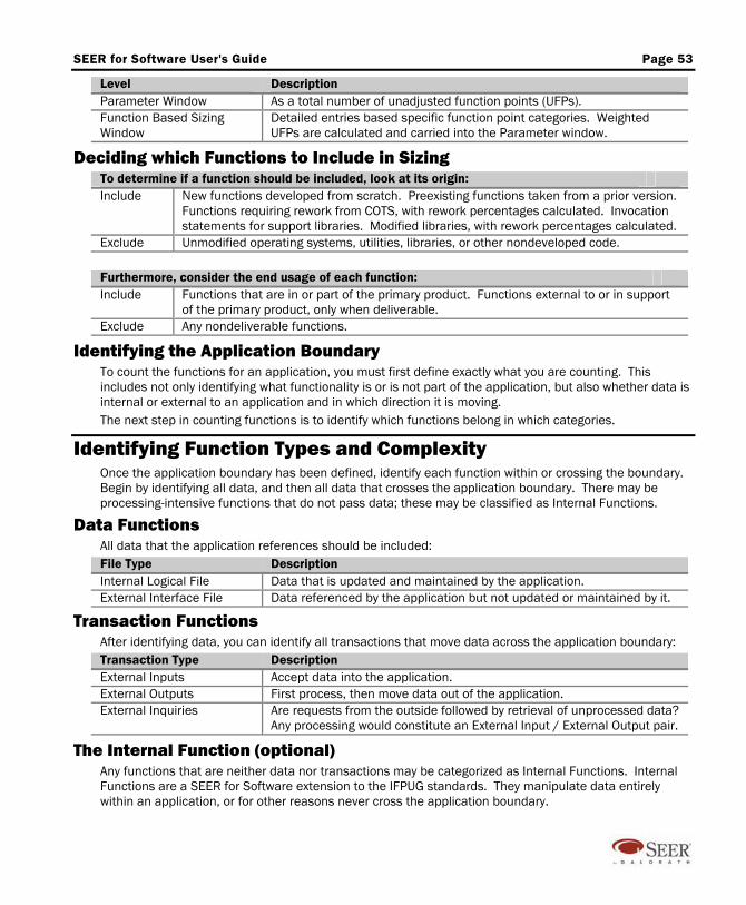
SEER for Software User's Guide Page 53
Level Description Parameter Window As a total number of unadjusted function points (UFPs). Function Based Sizing Window
Detailed entries based specific function point categories. Weighted UFPs are calculated and carried into the Parameter window.
Deciding which Functions to Include in Sizing To determine if a function should be included, look at its origin: Include New functions developed from scratch. Preexisting functions taken from a prior version.
Functions requiring rework from COTS, with rework percentages calculated. Invocation statements for support libraries. Modified libraries, with rework percentages calculated.
Exclude Unmodified operating systems, utilities, libraries, or other nondeveloped code.
Furthermore, consider the end usage of each function: Include Functions that are in or part of the primary product. Functions external to or in support
of the primary product, only when deliverable. Exclude Any nondeliverable functions.
Identifying the Application Boundary To count the functions for an application, you must first define exactly what you are counting. This includes not only identifying what functionality is or is not part of the application, but also whether data is internal or external to an application and in which direction it is moving. The next step in counting functions is to identify which functions belong in which categories.
Identifying Function Types and Complexity Once the application boundary has been defined, identify each function within or crossing the boundary. Begin by identifying all data, and then all data that crosses the application boundary. There may be processing-intensive functions that do not pass data; these may be classified as Internal Functions.
Data Functions All data that the application references should be included: File Type Description Internal Logical File Data that is updated and maintained by the application. External Interface File Data referenced by the application but not updated or maintained by it.
Transaction Functions After identifying data, you can identify all transactions that move data across the application boundary: Transaction Type Description External Inputs Accept data into the application. External Outputs First process, then move data out of the application. External Inquiries Are requests from the outside followed by retrieval of unprocessed data?
Any processing would constitute an External Input / External Output pair.
The Internal Function (optional) Any functions that are neither data nor transactions may be categorized as Internal Functions. Internal Functions are a SEER for Software extension to the IFPUG standards. They manipulate data entirely within an application, or for other reasons never cross the application boundary.
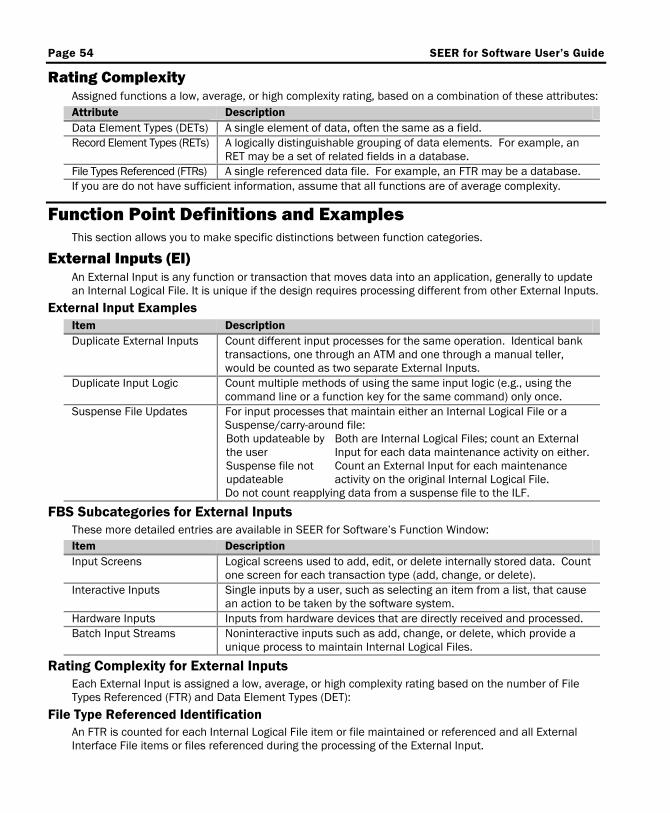
Page 54 SEER for Software User’s Guide
Rating Complexity Assigned functions a low, average, or high complexity rating, based on a combination of these attributes: Attribute Description Data Element Types (DETs) A single element of data, often the same as a field. Record Element Types (RETs) A logically distinguishable grouping of data elements. For example, an
RET may be a set of related fields in a database. File Types Referenced (FTRs) A single referenced data file. For example, an FTR may be a database. If you are do not have sufficient information, assume that all functions are of average complexity.
Function Point Definitions and Examples This section allows you to make specific distinctions between function categories.
External Inputs (EI) An External Input is any function or transaction that moves data into an application, generally to update an Internal Logical File. It is unique if the design requires processing different from other External Inputs.
External Input Examples Item Description Duplicate External Inputs Count different input processes for the same operation. Identical bank
transactions, one through an ATM and one through a manual teller, would be counted as two separate External Inputs.
Duplicate Input Logic Count multiple methods of using the same input logic (e.g., using the command line or a function key for the same command) only once.
Suspense File Updates For input processes that maintain either an Internal Logical File or a Suspense/carry-around file: Both updateable by the user
Both are Internal Logical Files; count an External Input for each data maintenance activity on either.
Suspense file not updateable
Count an External Input for each maintenance activity on the original Internal Logical File.
Do not count reapplying data from a suspense file to the ILF.
FBS Subcategories for External Inputs These more detailed entries are available in SEER for Software’s Function Window: Item Description Input Screens Logical screens used to add, edit, or delete internally stored data. Count
one screen for each transaction type (add, change, or delete). Interactive Inputs Single inputs by a user, such as selecting an item from a list, that cause
an action to be taken by the software system. Hardware Inputs Inputs from hardware devices that are directly received and processed. Batch Input Streams Noninteractive inputs such as add, change, or delete, which provide a
unique process to maintain Internal Logical Files.
Rating Complexity for External Inputs Each External Input is assigned a low, average, or high complexity rating based on the number of File Types Referenced (FTR) and Data Element Types (DET):
File Type Referenced Identification An FTR is counted for each Internal Logical File item or file maintained or referenced and all External Interface File items or files referenced during the processing of the External Input.

SEER for Software User's Guide Page 55
Data Element Type Identification The DET count is the maximum number of user-recognizable data elements that are maintained as an Internal Logical File by the External Input. DETs are credited to the External Input for: Item Description Internal Logical Files Each data element which the External Input can maintain as an ILF. User-specified Actions Actions taken by the External Input, specified by commands or function
keys — one DET per External Input, not per command or function key. Navigational keys are not counted.
Internal Fields Fields not entered by the user but maintained as Internal Logical Files through External Input.
Messages Error or confirmation messages resulting from input are each counted as an additional DET for the input.
Duplicate fields are not counted if they are: Duplicate Field Description From the same user input Duplicate fields created by the same user input. Duplicated for technical reasons
Fields that appear more than once in the Internal Logical File because of technology or implementation techniques should be counted only once.
1 to 4 DET 5 to 15 DET 16 or More DET 0 to 1 FTR Low Low Average 2 FTR Low Average High 3 or More FTR Average High High
Complexity Rating Table for External Inputs
External Outputs (EO) An External Output is any function or transaction that formats data and moves it out of the application boundary in a format that can be used by an external source.
External Output Examples Item Description Reports Each report produced by the application is an External Output. Reports
with identical formatting and different data are counted separately. Duplicate Reports Identical reports on different media are counted separately, since the
processing required to produce them is unique. Online Reports Online output of data that is not the output side of an External Inquiry. Error or Confirmation Messages
All error or confirmation messages for a single External Input are counted together as one External Output, with several DETs.
Derived Data Derived data that does not necessarily update a file.
Graphical Formats Count each different graphical display as an External Output.
Report Generator Each unique report produced by a report generator is an External Output.
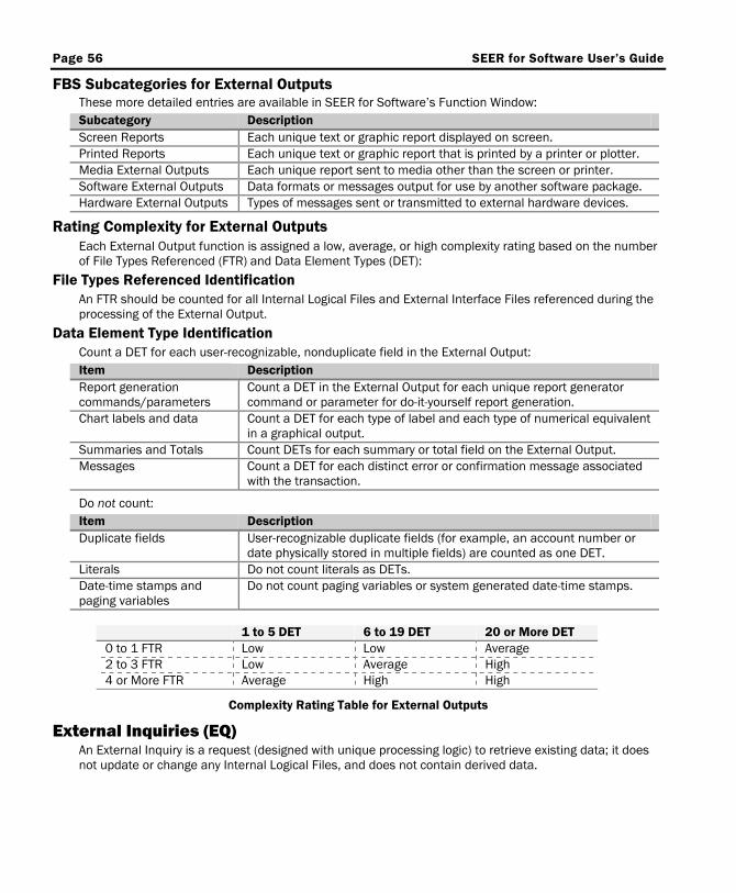
Page 56 SEER for Software User’s Guide
FBS Subcategories for External Outputs These more detailed entries are available in SEER for Software’s Function Window: Subcategory Description Screen Reports Each unique text or graphic report displayed on screen. Printed Reports Each unique text or graphic report that is printed by a printer or plotter. Media External Outputs Each unique report sent to media other than the screen or printer. Software External Outputs Data formats or messages output for use by another software package. Hardware External Outputs Types of messages sent or transmitted to external hardware devices.
Rating Complexity for External Outputs Each External Output function is assigned a low, average, or high complexity rating based on the number of File Types Referenced (FTR) and Data Element Types (DET):
File Types Referenced Identification An FTR should be counted for all Internal Logical Files and External Interface Files referenced during the processing of the External Output.
Data Element Type Identification Count a DET for each user-recognizable, nonduplicate field in the External Output: Item Description Report generation commands/parameters
Count a DET in the External Output for each unique report generator command or parameter for do-it-yourself report generation.
Chart labels and data Count a DET for each type of label and each type of numerical equivalent in a graphical output.
Summaries and Totals Count DETs for each summary or total field on the External Output. Messages Count a DET for each distinct error or confirmation message associated
with the transaction.
Do not count: Item Description Duplicate fields User-recognizable duplicate fields (for example, an account number or
date physically stored in multiple fields) are counted as one DET. Literals Do not count literals as DETs. Date-time stamps and paging variables
Do not count paging variables or system generated date-time stamps.
1 to 5 DET 6 to 19 DET 20 or More DET 0 to 1 FTR Low Low Average 2 to 3 FTR Low Average High 4 or More FTR Average High High
Complexity Rating Table for External Outputs
External Inquiries (EQ) An External Inquiry is a request (designed with unique processing logic) to retrieve existing data; it does not update or change any Internal Logical Files, and does not contain derived data.
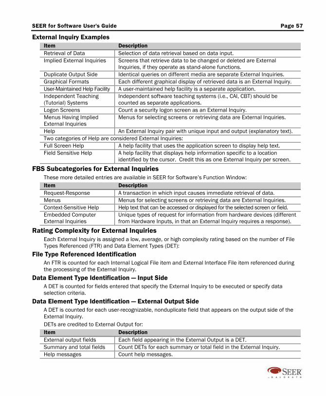
SEER for Software User's Guide Page 57
External Inquiry Examples Item Description Retrieval of Data Selection of data retrieval based on data input. Implied External Inquiries Screens that retrieve data to be changed or deleted are External
Inquiries, if they operate as stand-alone functions. Duplicate Output Side Identical queries on different media are separate External Inquiries. Graphical Formats Each different graphical display of retrieved data is an External Inquiry. User-Maintained Help Facility A user-maintained help facility is a separate application. Independent Teaching (Tutorial) Systems
Independent software teaching systems (i.e., CAI, CBT) should be counted as separate applications.
Logon Screens Count a security logon screen as an External Inquiry. Menus Having Implied External Inquiries
Menus for selecting screens or retrieving data are External Inquiries.
Help An External Inquiry pair with unique input and output (explanatory text). Two categories of Help are considered External Inquiries: Full Screen Help A help facility that uses the application screen to display help text. Field Sensitive Help A help facility that displays help information specific to a location
identified by the cursor. Credit this as one External Inquiry per screen.
FBS Subcategories for External Inquiries These more detailed entries are available in SEER for Software’s Function Window: Item Description Request-Response A transaction in which input causes immediate retrieval of data. Menus Menus for selecting screens or retrieving data are External Inquiries. Context-Sensitive Help Help text that can be accessed or displayed for the selected screen or field. Embedded Computer External Inquiries
Unique types of request for information from hardware devices (different from Hardware Inputs, in that an External Inquiry requires a response).
Rating Complexity for External Inquiries Each External Inquiry is assigned a low, average, or high complexity rating based on the number of File Types Referenced (FTR) and Data Element Types (DET):
File Type Referenced Identification An FTR is counted for each Internal Logical File item and External Interface File item referenced during the processing of the External Inquiry.
Data Element Type Identification — Input Side A DET is counted for fields entered that specify the External Inquiry to be executed or specify data selection criteria.
Data Element Type Identification — External Output Side A DET is counted for each user-recognizable, nonduplicate field that appears on the output side of the External Inquiry. DETs are credited to External Output for: Item Description External output fields Each field appearing in the External Output is a DET. Summary and total fields Count DETs for each summary or total field in the External Inquiry. Help messages Count help messages.
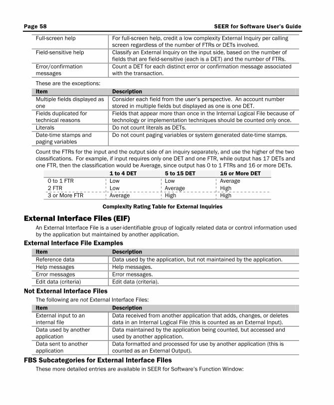
Page 58 SEER for Software User’s Guide
Full-screen help For full-screen help, credit a low complexity External Inquiry per calling screen regardless of the number of FTRs or DETs involved.
Field-sensitive help Classify an External Inquiry on the input side, based on the number of fields that are field-sensitive (each is a DET) and the number of FTRs.
Error/confirmation messages
Count a DET for each distinct error or confirmation message associated with the transaction.
These are the exceptions: Item Description Multiple fields displayed as one
Consider each field from the user’s perspective. An account number stored in multiple fields but displayed as one is one DET.
Fields duplicated for technical reasons
Fields that appear more than once in the Internal Logical File because of technology or implementation techniques should be counted only once.
Literals Do not count literals as DETs. Date-time stamps and paging variables
Do not count paging variables or system generated date-time stamps.
Count the FTRs for the input and the output side of an inquiry separately, and use the higher of the two classifications. For example, if input requires only one DET and one FTR, while output has 17 DETs and one FTR, then the classification would be Average, since output has 0 to 1 FTRs and 16 or more DETs.
1 to 4 DET 5 to 15 DET 16 or More DET 0 to 1 FTR Low Low Average 2 FTR Low Average High 3 or More FTR Average High High
Complexity Rating Table for External Inquiries
External Interface Files (EIF) An External Interface File is a user-identifiable group of logically related data or control information used by the application but maintained by another application.
External Interface File Examples Item Description Reference data Data used by the application, but not maintained by the application. Help messages Help messages. Error messages Error messages. Edit data (criteria) Edit data (criteria).
Not External Interface Files The following are not External Interface Files: Item Description External input to an internal file
Data received from another application that adds, changes, or deletes data in an Internal Logical File (this is counted as an External Input).
Data used by another application
Data maintained by the application being counted, but accessed and used by another application.
Data sent to another application
Data formatted and processed for use by another application (this is counted as an External Output).
FBS Subcategories for External Interface Files These more detailed entries are available in SEER for Software’s Function Window:

SEER for Software User's Guide Page 59
Item Description Reference Data Data groupings that are used by the software but are not changed — for
example, lookup tables, read-only data files, or master lists. Fixed Messages Messages used by the software but not changed — for example, error
messages, help messages, or system status messages. Shared Data Files Data files or databases created external to the application but used by it.
Rating Complexity for External Interface Files Each External Interface File is assigned a low, average, or high complexity rating based on the number of Record Element Types (RETs) and Data Element Types (DETs):
Record Element Type Identification These are logical subgroupings based on the user’s view of the data. Each unique record type is a RET. If there are no further logical groupings to fields then there is only one RET. Exclude header and trailer records (unless requested for audit), as well as record types required by physical space limitations.
Data Element Type Identification These are user-recognizable, non-duplicate fields residing in the External Interface File. DETs are credited to External Interface files for: Item Description External interface fields Each field in an External Interface File may be a DET.
These are the exceptions: Item Description Multiple fields displayed as one
Consider each field from the user’s perspective. An account number stored in multiple fields but displayed as one is one DET.
Fields duplicated for technical reasons
Fields that appear more than once in the Internal Logical File because of technology or implementation techniques should be counted only once.
Fields duplicated to provide multiple occurrences of data
Count repeating fields that are identical in format and exist to provide multiple occurrences of a data value only once.
1 to 19 DET 20 to 50 DET 51 or More DET 1 RET Low Low Average 2 to 5 RET Low Average High 6 or More RET Average High High
Complexity Rating Table for External Interface Files
Internal Logical Files (ILF) An Internal Logical File is a user-identifiable set of logically related data or control information used and maintained by the application.
Internal Logical File Examples Item Description Backup data Backup data is counted only if specifically requested by the user due to
legal or similar requirements. Files maintained by multiple applications
Internal Logical Files maintained by more than one application are credited to both applications at the time each is counted.
FBS Subcategories for Internal Logical Files These more detailed entries are available in SEER for Software’s Function Window:
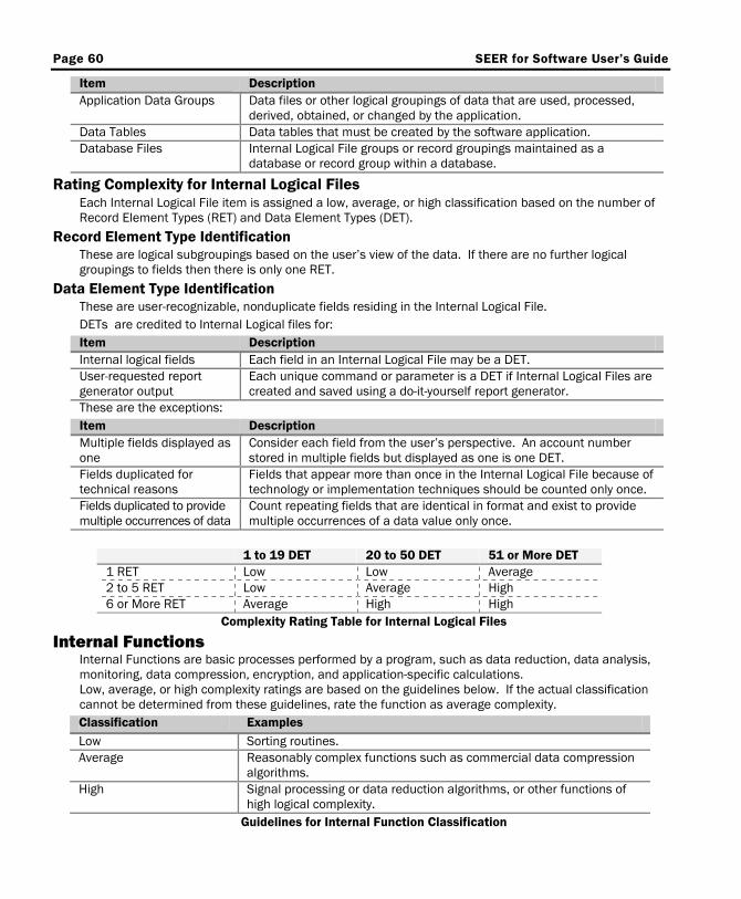
Page 60 SEER for Software User’s Guide
Item Description Application Data Groups Data files or other logical groupings of data that are used, processed,
derived, obtained, or changed by the application. Data Tables Data tables that must be created by the software application. Database Files Internal Logical File groups or record groupings maintained as a
database or record group within a database.
Rating Complexity for Internal Logical Files Each Internal Logical File item is assigned a low, average, or high classification based on the number of Record Element Types (RET) and Data Element Types (DET).
Record Element Type Identification These are logical subgroupings based on the user’s view of the data. If there are no further logical groupings to fields then there is only one RET.
Data Element Type Identification These are user-recognizable, nonduplicate fields residing in the Internal Logical File. DETs are credited to Internal Logical files for: Item Description Internal logical fields Each field in an Internal Logical File may be a DET. User-requested report generator output
Each unique command or parameter is a DET if Internal Logical Files are created and saved using a do-it-yourself report generator.
These are the exceptions: Item Description Multiple fields displayed as one
Consider each field from the user’s perspective. An account number stored in multiple fields but displayed as one is one DET.
Fields duplicated for technical reasons
Fields that appear more than once in the Internal Logical File because of technology or implementation techniques should be counted only once.
Fields duplicated to provide multiple occurrences of data
Count repeating fields that are identical in format and exist to provide multiple occurrences of a data value only once.
1 to 19 DET 20 to 50 DET 51 or More DET 1 RET Low Low Average 2 to 5 RET Low Average High 6 or More RET Average High High
Complexity Rating Table for Internal Logical Files
Internal Functions Internal Functions are basic processes performed by a program, such as data reduction, data analysis, monitoring, data compression, encryption, and application-specific calculations. Low, average, or high complexity ratings are based on the guidelines below. If the actual classification cannot be determined from these guidelines, rate the function as average complexity. Classification Examples Low Sorting routines. Average Reasonably complex functions such as commercial data compression
algorithms. High Signal processing or data reduction algorithms, or other functions of
high logical complexity. Guidelines for Internal Function Classification
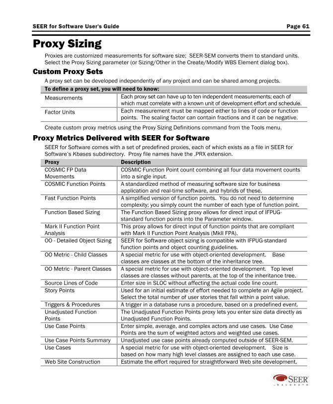
SEER for Software User's Guide Page 61
Proxy Sizing Proxies are customized measurements for software size; SEER-SEM converts them to standard units. Select the Proxy Sizing parameter (or Sizing/Other in the Create/Modify WBS Element dialog box).
Custom Proxy Sets A proxy set can be developed independently of any project and can be shared among projects. To define a proxy set, you will need to know:
Measurements Each proxy set can have up to ten independent measurements; each of which must correlate with a known unit of development effort and schedule.
Factor Units Each measurement must be mapped either to lines of code or function points. The scaling factor can contain fractions and it can be negative.
Create custom proxy metrics using the Proxy Sizing Definitions command from the Tools menu.
Proxy Metrics Delivered with SEER for Software SEER for Software comes with a set of predefined proxies, each of which exists as a file in SEER for Software’s Kbases subdirectory. Proxy file names have the .PRX extension. Proxy Description COSMIC FP Data Movements
COSMIC Function Point count combining all four data movement counts into a single input.
COSMIC Function Points A standardized method of measuring software size for business application and real-time software, and hybrids of these.
Fast Function Points A simplified version of function points. You do not need to determine complexity; you simply count the number of each type of function point.
Function Based Sizing The Function Based Sizing proxy allows for direct input of IFPUG-standard function points into the Parameter window.
Mark II Function Point Analysis
This proxy allows for direct input of function points that are compliant with Mark II Function Point Analysis (MkII FPA).
OO - Detailed Object Sizing SEER for Software object sizing is compatible with IFPUG-standard function points and object counting guidelines.
OO Metric - Child Classes A special metric for use with object-oriented development. Base classes are classes at the bottom of the inheritance tree.
OO Metric - Parent Classes A special metric for use with object-oriented development. Top level classes are classes without parents, at the top of the inheritance tree.
Source Lines of Code Enter size in SLOC without affecting the actual code line count. Story Points Used for an initial estimate of effort needed to complete an Agile project.
Select the total number of user stories that fall within a point value. Triggers & Procedures A trigger in a database runs a procedure, based on a predefined event. Unadjusted Function Points
The Unadjusted Function Points proxy lets you enter size data directly as Unadjusted Function Points.
Use Case Points Enter simple, average, and complex actors and use cases. Use Case Points are the sum of weighted actors and weighted use cases.
Use Case Points Summary Unadjusted use case points already computed outside of SEER-SEM. Use Cases A special metric for use with object-oriented development. Size is
based on how many high level classes are assigned to each use case. Web Site Construction Estimate the effort required for straightforward Web site development.
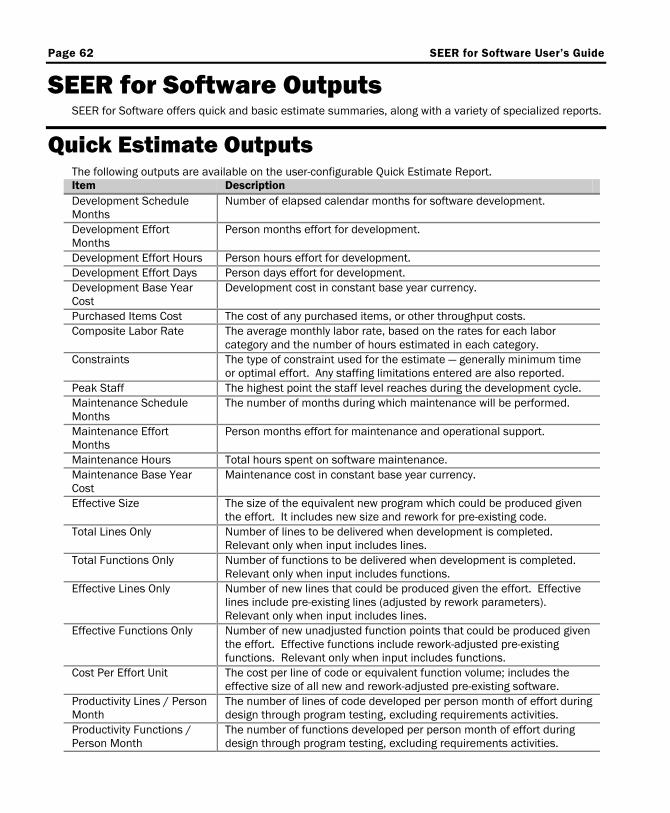
Page 62 SEER for Software User’s Guide
SEER for Software Outputs SEER for Software offers quick and basic estimate summaries, along with a variety of specialized reports.
Quick Estimate Outputs The following outputs are available on the user-configurable Quick Estimate Report. Item Description Development Schedule Months
Number of elapsed calendar months for software development.
Development Effort Months
Person months effort for development.
Development Effort Hours Person hours effort for development. Development Effort Days Person days effort for development. Development Base Year Cost
Development cost in constant base year currency.
Purchased Items Cost The cost of any purchased items, or other throughput costs. Composite Labor Rate The average monthly labor rate, based on the rates for each labor
category and the number of hours estimated in each category. Constraints The type of constraint used for the estimate — generally minimum time
or optimal effort. Any staffing limitations entered are also reported. Peak Staff The highest point the staff level reaches during the development cycle. Maintenance Schedule Months
The number of months during which maintenance will be performed.
Maintenance Effort Months
Person months effort for maintenance and operational support.
Maintenance Hours Total hours spent on software maintenance. Maintenance Base Year Cost
Maintenance cost in constant base year currency.
Effective Size The size of the equivalent new program which could be produced given the effort. It includes new size and rework for pre-existing code.
Total Lines Only Number of lines to be delivered when development is completed. Relevant only when input includes lines.
Total Functions Only Number of functions to be delivered when development is completed. Relevant only when input includes functions.
Effective Lines Only Number of new lines that could be produced given the effort. Effective lines include pre-existing lines (adjusted by rework parameters). Relevant only when input includes lines.
Effective Functions Only Number of new unadjusted function points that could be produced given the effort. Effective functions include rework-adjusted pre-existing functions. Relevant only when input includes functions.
Cost Per Effort Unit The cost per line of code or equivalent function volume; includes the effective size of all new and rework-adjusted pre-existing software.
Productivity Lines / Person Month
The number of lines of code developed per person month of effort during design through program testing, excluding requirements activities.
Productivity Functions / Person Month
The number of functions developed per person month of effort during design through program testing, excluding requirements activities.
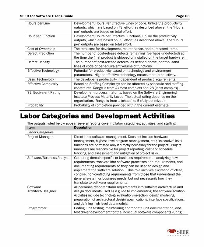
SEER for Software User's Guide Page 63
Hours per Line Development Hours Per Effective Lines of code. Unlike the productivity outputs, which are based on FSI effort (as described above), the "Hours per" outputs are based on total effort.
Hour per Function Development Hours per Effective Functions. Unlike the productivity outputs, which are based on FSI effort (as described above), the "Hours per" outputs are based on total effort.
Cost of Ownership The total cost for development, maintenance, and purchased items. Defect Prediction The number of post-release defects remaining (perhaps undetected) at
the time the final product is shipped or installed on the target hardware. Defect Density The number of post-release defects, as defined above, per thousand
lines of code or per equivalent volume of functions. Effective Technology Potential for productivity based on technology and environment
parameters. Higher effective technology means more productivity. Basic Technology The developer's productivity independent of product requirements. Effective Complexity Based on Staffing Complexity; can be affected by schedule and staffing
constraints. Range is from 4 (most complex) and 28 (least complex). SEI Equivalent Rating Development process maturity, based on the Software Engineering
Institute Process Maturity Level. The actual rating depends on the organization. Range is from 1 (chaos) to 5 (fully optimized).
Probability Probability of completion provided within the current estimate.
Labor Categories and Development Activities The outputs listed below appear several reports covering labor categories, activities, and staffing. Item Description Labor Categories Project Manager Direct labor software management. Does not include hardware
management, highest level program management, etc.; "executive"-level functions are permitted only if directly necessary for the project. Project managers are responsible for project reporting, cost and schedule tracking, and assessment and mitigation of project risks.
Software/Business Analyst Gathering domain specific or business requirements, analyzing how requirements translate into software processes and requirements, and documenting requirements so they can be used to design and implement the software solution. This role involves elicitation of clear, concise, non-conflicting requirements from those that understand the general system or business needs, but not necessarily how they translate to software requirements.
Software Architect/Designer
All personnel who transform requirements into software architecture and design documents used as a guide to implementing the software solution. Activities include technology evaluation/selection, design modeling, preparation of architectural design specifications, interface specifications, and defining high level data models.
Programmer Coding, unit testing, maintaining appropriate unit documentation, and test driver development for the individual software components (Units).
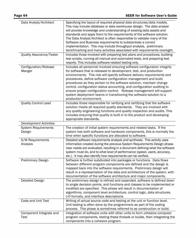
Page 64 SEER for Software User’s Guide
Data Analyst/Architect Specifying the layout of required physical data structures/data models. This may include database or data warehouse design. The data analyst will provide knowledge and understanding of existing data assets and standards and apply them to the requirements of the software solution. The Data Analyst/Architect is often responsible to validate many of the Software and Business requirements to substantiate a correct implementation. This may include throughput analysis, preliminary benchmarking and many activities associated with requirements oversight.
Quality Assurance/Tester Includes those involved with preparing test plans and procedures, building test scripts, running all manual and automated tests, and preparing test reports. This includes software-related testing only.
Configuration/Release Manger
Includes all personnel involved ensuring software configuration integrity for software that is released to development, test, and production environments. This role will specify software delivery requirements and procedures, define software configuration management and build procedures as they pertain to the software solution, maintain change control, configuration status accounting, and configuration auditing to ensure proper configuration control. Release management will support system deployment teams in transitioning the software solution to a production environment.
Quality Control Lead Includes those responsible for verifying and certifying that the software solution meets all required quality standards. They are involved with any quality engineering functions and quality inspection and audits. This includes ensuring that quality is built in to the product and developing appropriate standards.
Development Activities System Requirements Design
The creation of initial system requirements and related tasks. If the system has both software and hardware components, this is normally the time when specific functions are allocated to software.
S/W Requirements Analysis
Detailed software requirements analysis and synthesis. This activity uses information created during the previous System Requirements Design phase. User needs are evaluated, resulting in a document defining what the software system must do, and to what level of performance (speed, users, accuracy, etc.). It may also identify how requirements can be verified.
Preliminary Design Software is further subdivided into packages or functions. Data flows between different program components are defined and the design is mapped back into the software requirements. Preliminary design will result in a representation of the data and architecture of the system, with documentation of the software architecture and major components.
Detailed Design The preliminary design is refined and expanded, software is defined down to single decision points, and functions and classes to be implemented or modified are specified. This phase will result in documentation of algorithms, component level architecture, control logic, data structures, I/O formats, and interface descriptions.
Code and Unit Test Writing of actual source code and testing at the unit or function level. Unit testing is often done by the programmers as part of the coding process. This phase is sometimes referred to as construction or build.
Component Integrate and Test
Integration of software units with other units to form cohesive computer program components, testing these threads or builds, then integrating the components into a cohesive program.
SEER for Software User's Guide Page 65
Program Test Formal testing software to determine compliance with requirements. Each cohesive computer program is tested as a whole.
System Integrate Through OT&E
Where software to software and software to hardware integration is performed and where the final system is tested with live data in a real-world environment.
Maintenance Maintenance effort for operational software. This effort may include corrective and adaptive changes (sustaining engineering) plus the addition of new functions and enhancements, depending on the scenario defined by the maintenance-unique parameters.
Development Total Effort by labor category for all development activities. Life Cycle Total Effort by labor category for all development activities plus maintenance.
Exporting Data from SEER for Software There are several ways to export data from SEER for Software, depending on the type of data and the way that you intend to use it:
Tools / Flexible Export Flexible export is the most versatile method of exporting data from SEER for Software; it lets you create customized reports that can be exported as text files, copied onto the Windows clipboard, or displayed in the Reports window. You can also format information for other applications, including project management tools and spreadsheets. You can create templates that capture any combination of SEER for Software outputs or inputs: Display the outputs by rows or by columns. Display outputs for a single unit, a unit and its subordinate elements, or the entire project. Select a delimiter for your output (tab, comma, etc.).
Several templates are included in SEER for Software; you can use them as starting points when you create your own.
Tools / Export Commands Export Commands exports all or part of a project as a server mode script — a set of commands which you can use to create a project from the within SEER For Software, from a batch file, or from another application. You can also paste the commands directly into SEER for Software.
Tools / Export Report Export Report allows you to export SEER for Software reports in Excel, HTML, PDF, or other formats. You can select reports, and export the entire project, the selected work element, or the selected branch of the project tree. Exported data may be written to a file, a mail message, or even an exchange server folder.
Linking to Microsoft Project An effective way to create a project plan based on your SEER for Software data is with Integration to MS Project. (See Using Edition Features / Microsoft Project Integration, below.) There are two options on the
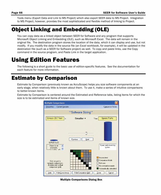
Page 66 SEER for Software User’s Guide
Tools menu (Export Data and Link to MS Project) which also export SEER data to MS Project. Integration to MS Project, however, provides the most sophisticated and flexible method of linking to Project.
Object Linking and Embedding (OLE) You can copy data as a linked object between SEER for Software and any program that supports Microsoft Object Linking and Embedding (OLE), such as Microsoft Excel. The data will remain in the original file. The destination program stores the location of the data, which it can display and use, but not modify. If you modify the data in the source file (an Excel workbook, for example), it will be updated in the destination file (such as a SEER for Software project) as well. To copy and paste links, use the Copy command in the source program, and Paste Link in the target application.
Using Edition Features The following is a short guide to the basic use of edition-specific features. See the documentation for each feature for more information.
Estimate by Comparison Estimate by Comparison (previously known as AccuScope) helps you size software components at an early stage, when relatively little is known about them. To use it, make a series of intuitive comparisons to better-known items. Estimate by Comparison is centered around the Estimated and Reference tabs, listing items for which the size is to be estimated and items of known size.
Multiple Comparisons Dialog Box
SEER for Software User's Guide Page 67
Specifying Items To Be Estimated To enter items to be estimated, click on the Estimated tab, so that the Estimated Items list is displayed. You can create a new item by clicking on the Add Item button, then entering the item name, origin (acquisition method), language, and description in the Item information dialog box. You also can paste items in from Excel or other applications, provided they conform to a standard format. A simple list of names is one of the permissible formats.
Specifying Reference (Known) Items To enter known items for comparison, click on the Reference tab, so that the Reference Items list is displayed. You can select analogies and items from the repository, and you can enter items from scratch. You can paste items in from Excel or other applications, provided they conform to a standard format. Supported formats include lists of names and numbers, as well as more elaborate formats.
Comparing Items Against Each Other To estimate the size of the items on the Estimated list, click on the Multiple Comparisons button. In the Multiple Comparisons dialog box, you can compare each estimated item with each reference item and with the other estimated items. The comparison is based on your judgment of the items' relative sizes. You can compare items using a single or triple slider (for a Least/Likely/Most range of comparisons), or by entering percentage differences. To change the comparison method, use the Properties menu in the Multiple Comparisons dialog box. The comparison grid shows which pairs of items have been compared and which have not; click on the Consistency button to see whether the comparisons which you have made are consistent with each other. To exit the Multiple Comparisons dialog box with your comparison data, click on Done. The items in the Estimated list will have sizes based on your comparisons.
Pasting Items into SEER for Software You can use the Edit menu Copy and Export To selections to copy Estimate by Comparison items individually, as a list, or as SEER for Software program or component elements or size parameters. When you paste an item into SEER for Software as a Program WBS element, it will be placed at Level 2, the first level of indentation below the Project-level rollup. The item's location in the project (and its level, when you paste it as a Component) will depend on the WBS item which you select before you paste. When you export an item as a size parameter, you can paste it into a SEER for Software Program, Component, or Unit. To paste the data, select either the work element in the project WBS list or any of its parameters, then select Paste from the Edit or right-click context menus. The size data will automatically be pasted into the corresponding sizing parameter(s).
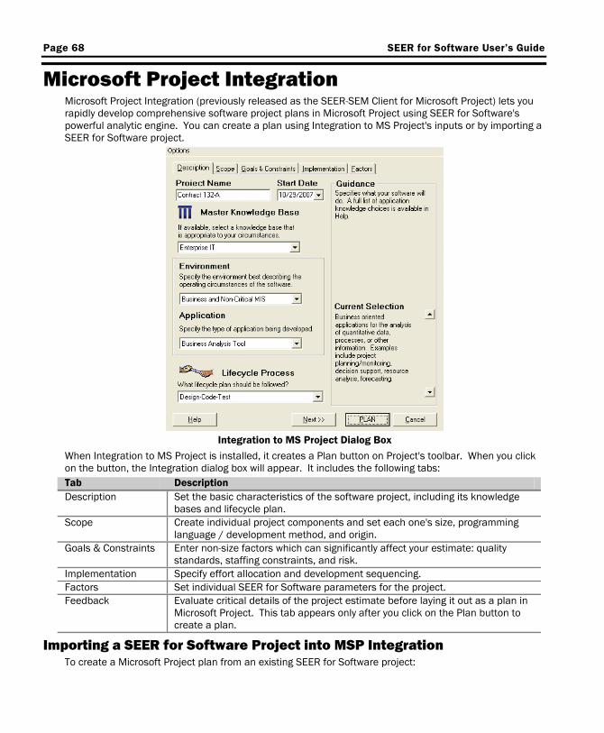
Page 68 SEER for Software User’s Guide
Microsoft Project Integration Microsoft Project Integration (previously released as the SEER-SEM Client for Microsoft Project) lets you rapidly develop comprehensive software project plans in Microsoft Project using SEER for Software's powerful analytic engine. You can create a plan using Integration to MS Project's inputs or by importing a SEER for Software project.
Integration to MS Project Dialog Box
When Integration to MS Project is installed, it creates a Plan button on Project's toolbar. When you click on the button, the Integration dialog box will appear. It includes the following tabs: Tab Description Description Set the basic characteristics of the software project, including its knowledge
bases and lifecycle plan. Scope Create individual project components and set each one's size, programming
language / development method, and origin. Goals & Constraints Enter non-size factors which can significantly affect your estimate: quality
standards, staffing constraints, and risk. Implementation Specify effort allocation and development sequencing. Factors Set individual SEER for Software parameters for the project. Feedback Evaluate critical details of the project estimate before laying it out as a plan in
Microsoft Project. This tab appears only after you click on the Plan button to create a plan.
Importing a SEER for Software Project into MSP Integration To create a Microsoft Project plan from an existing SEER for Software project:

SEER for Software User's Guide Page 69
1. Select Import SEER for Software Project from the Options menu in the upper left-hand corner of the Integration to MS Project dialog box.
2. In the Open dialog box, select the project that you want to import and click on the Open button. 3. Integration to MS Project will display a message telling you that inputs which conflict with the
imported estimate have been disabled. Click on OK. 4. Integration to MS project will now contain the data from your SEER for Software project. The Scope,
Goals & Constraints and Factors tabs will be disabled. In the Description tab, the Project Name and Lifecycle Process inputs will be enabled. In the Implementation tab, you will be able to select or create a resource assignment.
5. Click on the PLAN button to produce a Microsoft Project plan.
Project Monitor & Control Project Monitor & Control (available as PPMC in earlier releases) allows you to use your SEER for Software estimate as a baseline for evaluating your project's actual progress at different points in the development process.
Project Monitor & Control Snapshot
Using Project Monitor & Control NOTE: If Project Monitor & Control is included in your SEER for Software edition, the Project Monitor & Control menu will be enabled. The first option on the menu makes Project Monitor & Control features active (checked) or inactive (unchecked). 1. Set a baseline. In SEER Project Monitor & Control, a baseline plan is a SEER for Software estimate
which you will use to measure the progress of your project. To set a baseline, first create an estimate for your project, if you have not already done so. When you are satisfied that the estimate represents your best understanding of the project based on the information available to you, select Save Current Estimate as Baseline from the Project Monitor & Control menu. This will freeze the
Page 70 SEER for Software User’s Guide
estimate so you can track against it. It is very similar to setting a reference; a baseline, however, is saved with the project file and will be there until you delete it.
2. Take Snapshots. Once the project is underway, you will need to enter actual project data. You do this by taking a snapshot — entering actual project data in the Project Monitor & Control Snapshots tab. To do this, select Project Monitor & Control Snapshots from SEER for Software's View menu, or click on the Project Monitor & Control Snapshots tab in the Inputs window. Click on either WC Snapshot (next) or AE Snapshot (next) to create a new snapshot. In the snapshot entry dialog box, you can switch between the Work Complete and Actual Effort entry screens by clicking on the Work Comp./Act. Effort button. Work Complete represents the percentage of each activity completed. Actual Effort represents the effort actually spent on development at the time of the snapshot.
3. Review the reports. After you have saved a baseline and entered at least one snapshot, you can evaluate the project's progress. In the Reports / Choose Active reports dialog box, select PMC Report. You can choose which items will appear in the report using the PMC Report Options dialog box (available from the Project Monitor & Control/PMC Options dialog box). There are five Project Monitor & Control charts: Schedule Accomplishments, Performance Indices, Defects Tracking, Health & Status Indicator, and Benchmark. They provide a quick, at-a-glance evaluation of your project's status in relation to the baseline plan.
4. Make appropriate schedule and staffing adjustments, if required. If your project is over-budget, behind-schedule, or otherwise falling behind the baseline, you may be able to make changes in the actual development project (adjust staffing to make more efficient use of personnel, for example) to bring it more in line with the baseline. When you are not able to make course-corrections in the actual project, you can update your estimate to reflect the project's progress, then use the updated estimate as a new baseline. Re-planning a project involves a review of your size, parameters, and other estimate assumptions; you can evaluate changes to your current estimate against your snapshot data without having to reset your baseline. This gives you the opportunity to study different scenarios before committing to a new estimate baseline. Make your current estimate visible on the PMC charts (by selecting Show Current Estimate in PMC Charts on the PMC Options dialog box) and turn on the current estimate on the PMC report (using the PMC Report Option). After adjusting your estimate based on the review, you can set it as the new baseline by selecting Save Current Estimate As Baseline from the Project Monitor & Control menu.
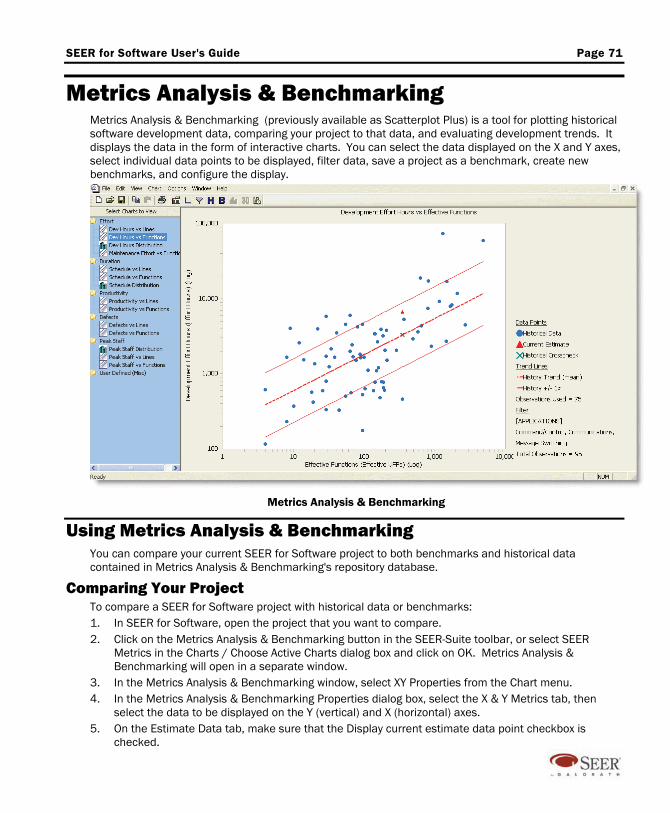
SEER for Software User's Guide Page 71
Metrics Analysis & Benchmarking Metrics Analysis & Benchmarking (previously available as Scatterplot Plus) is a tool for plotting historical software development data, comparing your project to that data, and evaluating development trends. It displays the data in the form of interactive charts. You can select the data displayed on the X and Y axes, select individual data points to be displayed, filter data, save a project as a benchmark, create new benchmarks, and configure the display.
Metrics Analysis & Benchmarking
Using Metrics Analysis & Benchmarking You can compare your current SEER for Software project to both benchmarks and historical data contained in Metrics Analysis & Benchmarking's repository database.
Comparing Your Project To compare a SEER for Software project with historical data or benchmarks: 1. In SEER for Software, open the project that you want to compare. 2. Click on the Metrics Analysis & Benchmarking button in the SEER-Suite toolbar, or select SEER
Metrics in the Charts / Choose Active Charts dialog box and click on OK. Metrics Analysis & Benchmarking will open in a separate window.
3. In the Metrics Analysis & Benchmarking window, select XY Properties from the Chart menu. 4. In the Metrics Analysis & Benchmarking Properties dialog box, select the X & Y Metrics tab, then
select the data to be displayed on the Y (vertical) and X (horizontal) axes. 5. On the Estimate Data tab, make sure that the Display current estimate data point checkbox is
checked.
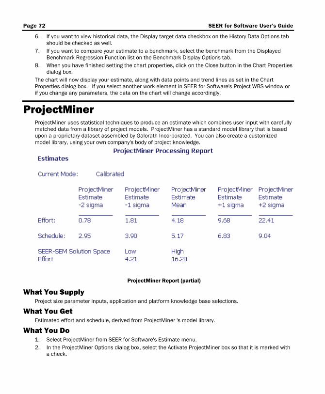
Page 72 SEER for Software User’s Guide
6. If you want to view historical data, the Display target data checkbox on the History Data Options tab should be checked as well.
7. If you want to compare your estimate to a benchmark, select the benchmark from the Displayed Benchmark Regression Function list on the Benchmark Display Options tab.
8. When you have finished setting the chart properties, click on the Close button in the Chart Properties dialog box.
The chart will now display your estimate, along with data points and trend lines as set in the Chart Properties dialog box. If you select another work element in SEER for Software's Project WBS window or if you change any parameters, the data on the chart will change accordingly.
ProjectMiner ProjectMiner uses statistical techniques to produce an estimate which combines user input with carefully matched data from a library of project models. ProjectMiner has a standard model library that is based upon a proprietary dataset assembled by Galorath Incorporated. You can also create a customized model library, using your own company's body of project knowledge.
ProjectMiner Report (partial)
What You Supply Project size parameter inputs, application and platform knowledge base selections.
What You Get Estimated effort and schedule, derived from ProjectMiner 's model library.
What You Do 1. Select ProjectMiner from SEER for Software's Estimate menu. 2. In the ProjectMiner Options dialog box, select the Activate ProjectMiner box so that it is marked with
a check.
SEER for Software User's Guide Page 73
3. Select the mode. If you want to view ProjectMiner output without changing your SEER for Software estimate, select Crosscheck Mode. If you decide to incorporate the data into your estimate, you can change the mode.
4. Click on Ok to exit the dialog box and activate ProjectMiner in the selected mode.
Your SEER for Software project will now include a ProjectMiner report. In Crosscheck mode, this will be the only change. In Calibrated Mode, your SEER for Software estimate will be adjusted to reflect the ProjectMiner estimate. In Replacement mode, your SEER for Software estimate will be replaced by ProjectMiner estimate data whenever appropriate. For ideal performance, ProjectMiner should be deactivated if you will be changing the Project WBS using server mode scripts or the Automation API.
What Goes On Inside ProjectMiner For ProjectMiner's purposes, platform and application knowledge bases can be organized into groups. All of the knowledge bases in a given group will produce similar estimates for the same project inputs. Statistical analysis of projects using knowledge bases in the same group will produce results which are applicable to other projects which use knowledge bases in that group. ProjectMiner uses your project application and platform knowledge base selections and size data as input. It looks at a table of application and platform equivalents, and finds the knowledge base groups which apply to your project. It selects the model that corresponds to these groups, and creates an estimate using that model, plus your size inputs.

Page 74 SEER for Software User’s Guide
This page can be used for notes and comments.