Embed Size (px)
Citation preview
629
Journal of Engineering Sciences
Assiut University
Faculty of Engineering
Vol. 42
No. 3
May 2014
Pages: 629-651
SEISMIC CAPACITY OF RC HOLLOW BLOCK
SLAB BUILDING AND RETROFITTING SYSTEMS
Waleed Abo El-Wafa Mohamed
Associate professor, Civil Engineering Department, Faculty of Engineering,
Assiut University, Assiut, Egypt. E-mail:[email protected]
Received 7 April 2014; revised 20 April 2014; accepted 25 April 2014
ABSTRACT
Retrofitting the seismically deficient structures before earthquakes provides a feasible approach to improve their load carrying capacity and reducing their vulnerability. This study presents an analytical assessment investigation on hollow block slab reinforced concrete building. The building is not designed according to seismic standards; moreover, hollow block slab systems may lack the sufficient lateral seismic resistance. Different retrofitting systems to enhance the seismic capacity of the target building are proposed and evaluated. These systems include strengthening the columns with reinforced concrete jackets or using internal shear walls or introducing steel chevron bracing. The target building before and after retrofitting is analyzed either as bare frames or considering masonry infill walls with different parameters. The three dimensional nonlinear pushover analysis procedures are used in evaluating the seismic performance of the original building and the retrofitted ones. The demand response spectra proposed by the Egyptian Code of Loads, ECOL 201, 2012 edition, for different seismic zones with different soil properties are utilized in the evaluation. Real seven earthquakes response spectra with maximum-scaled spectrum acceleration close to the one calculated for Cairo city are also applied. It is found that the original target building, before retrofitting, fails to fulfill the demands of neither many of the ECOL response spectra nor many of the applied real earthquakes. All the proposed retrofitting systems succeed in highly enhancing the seismic capacity of the original building. Considering masonry infill walls in the analysis has a crucial role on the seismic performance of the original building, the retrofitting systems can, due to the increase in the lateral strength, limit this effect.
Keywords: Hollow block slab building, Masonry infill walls, Pushover analysis, Strength and stiffness
1. Introduction
In the last decades, huge numbers of the reinforced concrete structures are constructed using hollow block reinforced concrete slabs. The main advantages of using this type of reinforced concrete slabs are that they provide an economical, lightweight slab system, unobstructed space, architectural flexibility and easier frame work [1]. However, in most cases, due to lack of deep strong beams, which can form with columns strong frame actions,
630
Waleed Abo El-Wafa Mohamed, Seismic capacity of RC hollow block slab building………
the resulted transverse stiffness may be low. This may lead to potential damage even when subjected to earthquakes with moderate intensity.
Substantial research efforts have been devoted to investigating the performance of engineering structures during earthquakes such as reinforced concrete buildings, minarets, masonry and wooden buildings. It was reported that hundreds of thousands of buildings suffered different types of damage during these earthquakes. During many earthquakes, the failure building mostly was non-engineered buildings where the buildings did not follow the building codes [2], [3]. However, some of engineered buildings suffered also from failure or collapse [4], [5]. Most of the existing buildings in developing countries have not been designed according to modern seismic methods. Many of these structures were designed taking only gravity loads into considerations and take into account little or no seismic provisions. As a result, many existing buildings have deficient lateral load resistance, insufficient energy dissipation and can rapidly lose their strength during earthquakes, leading to collapse. Extensive human and economic losses in many recent earthquakes have highlighted the seismic vulnerability of substandard reinforced concrete (RC) buildings [6] - [9]. Therefore, some efforts must be made to upgrade these structures towards more recent safety requirements, using available retrofit techniques to increase their safety levels and to improve the expected behavior during seismic activity in the future [10], [11].
The first edition of the ECOL containing seismic provisions was issued in 1993 [12]. In this code, the seismic base shear was seen to be a percentage of the total dead load of the structure. This percentage depends on the site seismicity, soil condition, the utilization importance, fundamental period and the type of seismic force resisting system. The second edition of this code of loads (ECOL 201) was issued in year 2003 [13]. The seismic provisions in this edition had experienced major significant changes related the previous edition. Egypt had been divided into five seismic regions according to design ground acceleration (ag) which ranges, in this edition, from 0.1 g to 0.25 g. Two types of response spectrum are provided. Modified versions of this code, under same title, were revealed in 2008 [14] and 2012 [15]. The seismic provisions in these editions of code of loads are almost, except some specific significant changes, similar to the provisions presented by the 2003 edition. These changes include appending a new seismic zone along with changing the seismic intensity of some towns. Some changes are also applied to the structural modeling, safety verification and period equations. It was found that the provisions in the 1993 edition [12] yield base shear much less than the values obtained using 2008 and following editions especially for low to medium height buildings located in medium and high seismic zones [16], [17].
Most of the existing RC buildings around the world use masonry infill panels (MI), which are intended to serve as internal partitions or external cladding, in their constructions. Although the masonry infill panels can be beneficial or detrimental to the seismic response of the structure, they are not usually considered in the analysis of frame structures. Hence once the ultimate strength of the structure is reached, a non-ductile deterioration follows, which reduces the energy dissipated by the structure and results in a brittle failure. The contribution of masonry infills may change the lateral load transfer mechanism of the structure from predominant frame actions to predominant truss actions [18]-[21]. The reality that the infill walls have significant contribution to the lateral performance of RC structures, either in a positive or negative way, and can highly alter the structural response of buildings was highly supported and illustrated by the performance of buildings in some recent earthquakes [22] - [24]. The ECOL renewed some general provisions related to the MI walls (called in this code Non- structural elements NSE).
631
JES, Assiut University, Faculty of Engineering, Vol. 42, No. 3, May2014, pp. 629–651
These provisions include that if the NSE are with risk impact on causalities or affect the main structure of building, they must be designed to resist seismic loads. If the NSE is with high importance or risk, the seismic analysis of the structure should include real representation of all building components. However, no provisions related to modeling of MI walls and the effect of openings is presented in the code.
Different retrofitting techniques were investigated in the last decades to upgrade the seismic performance of existing undamaged structures before being subjected to an earthquake, so that lateral resistance and ductility of a building may be increased. Usually, there are two main retrofitting techniques, the first is considered as non-conventional method, which incorporates base isolation and energy dissipation systems. This technique aims to increase the structural ductility and hence reduce the earthquake demand. The practical applicability of this technique is not so popular, at least till now. The second one is the system of strengthening and stiffening which is considered the most common seismic performance improvement strategies adopted for buildings with inadequate lateral force resisting systems. This approach includes adding new structural elements such as structural walls or steel bracing or the selective strengthening of deficient structural elements such as the use of concrete, steel jackets and fiber reinforced polymers. The philosophy here is to provide systems that are strong enough to resist the seismic forces and light enough to keep the structural elements from needing further reinforcement [25] – [28].
It is evident that there are relatively large number of seismic reliability studies in the literature concerning the evaluation and retrofitting of deficient buildings. However, to the best of my knowledge, there is a little information available concerning the seismic capacity assessment of the hollow block slab structures. Most of the available literature dealt with the comparison between hollow block and solid slab buildings [1], the heat transverse between blocks [29] and fissure analysis of hollow block slabs [30]. The subject of masonry infilled reinforced concrete frames had attracted many researchers over the past five decades. Their effort have been paid in many areas related to this subject such as modeling and idealization of infill walls [31], experimental investigations [32], [33], modeling infill openings as windows and doors [34] and numerical investigations [35], [36]. However, The interaction between the masonry infill walls and the hollow block slab buildings, before and after retrofitting need to be investigated.
The purpose of this study is to produce a seismic performance assessment of the lateral capacity of a six stories hollow block slab building which is not designed according to seismic standards. The plan dimensions of the building is 32.0 m x 15.0 m while the total height of the building is 19.0 m. Three different retrofitting techniques are suggested and evaluated, these techniques include strengthening the columns using reinforced concrete jackets, using shear walls around the stairs and introducing steel chevron bracing to the extreme marginal frames. Three dimensional nonlinear pushover analysis is adopted to evaluate the performance of the original and retrofitted building. The demand response spectra supposed by the ECOL 201, 2012 edition [15] and real earthquakes response spectra with maximum scaled spectrum acceleration close to the one calculated for Cairo city are used to evaluate the performance of the original and retrofitted building.
632
Waleed Abo El-Wafa Mohamed, Seismic capacity of RC hollow block slab building………
2. Description of original building
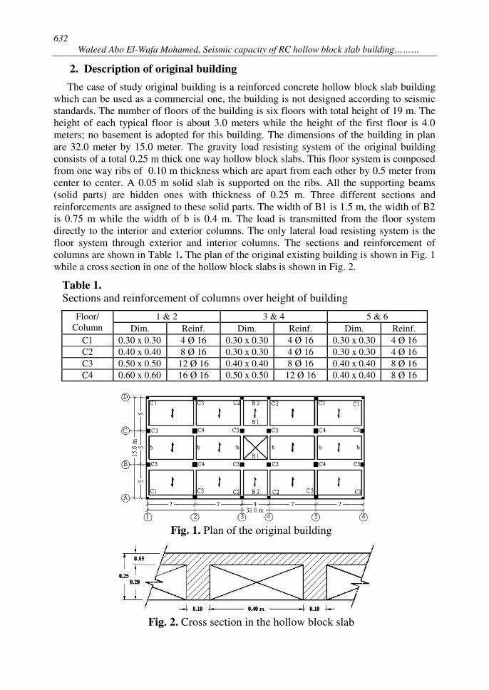
The case of study original building is a reinforced concrete hollow block slab building which can be used as a commercial one, the building is not designed according to seismic standards. The number of floors of the building is six floors with total height of 19 m. The height of each typical floor is about 3.0 meters while the height of the first floor is 4.0 meters; no basement is adopted for this building. The dimensions of the building in plan are 32.0 meter by 15.0 meter. The gravity load resisting system of the original building consists of a total 0.25 m thick one way hollow block slabs. This floor system is composed from one way ribs of 0.10 m thickness which are apart from each other by 0.5 meter from center to center. A 0.05 m solid slab is supported on the ribs. All the supporting beams (solid parts) are hidden ones with thickness of 0.25 m. Three different sections and reinforcements are assigned to these solid parts. The width of B1 is 1.5 m, the width of B2 is 0.75 m while the width of b is 0.4 m. The load is transmitted from the floor system directly to the interior and exterior columns. The only lateral load resisting system is the floor system through exterior and interior columns. The sections and reinforcement of columns are shown in Table 1. The plan of the original existing building is shown in Fig. 1
while a cross section in one of the hollow block slabs is shown in Fig. 2.
Table 1.
Sections and reinforcement of columns over height of building
Floor/ Column
1 & 2 3 & 4 5 & 6
Dim. Reinf. Dim. Reinf. Dim. Reinf.
C1 0.30 x 0.30 4 Ø 16 0.30 x 0.30 4 Ø 16 0.30 x 0.30 4 Ø 16
C2 0.40 x 0.40 8 Ø 16 0.30 x 0.30 4 Ø 16 0.30 x 0.30 4 Ø 16
C3 0.50 x 0.50 12 Ø 16 0.40 x 0.40 8 Ø 16 0.40 x 0.40 8 Ø 16
C4 0.60 x 0.60 16 Ø 16 0.50 x 0.50 12 Ø 16 0.40 x 0.40 8 Ø 16
Fig. 1. Plan of the original building
Fig. 2. Cross section in the hollow block slab
633
JES, Assiut University, Faculty of Engineering, Vol. 42, No. 3, May2014, pp. 629–651
The compressive strength of concrete used in the building is 22.50 MPa while the used steel is mild steel with yield strength of 280 MPa. The three dimensional nonlinear pushover analysis is carried out using ETABS software package, nonlinear version 9.6 [37]. Beams and columns are modeled as nonlinear elements with lumped plasticity specified at the end of elements. Cracked section stiffness for RC beams and columns are taken according to the ECOL.
3. Acceleration records
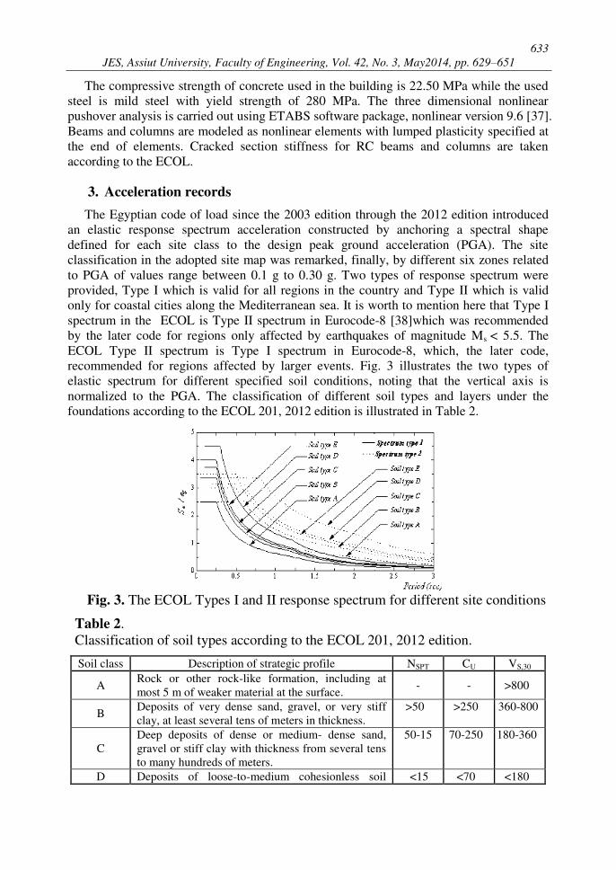
The Egyptian code of load since the 2003 edition through the 2012 edition introduced an elastic response spectrum acceleration constructed by anchoring a spectral shape defined for each site class to the design peak ground acceleration (PGA). The site classification in the adopted site map was remarked, finally, by different six zones related to PGA of values range between 0.1 g to 0.30 g. Two types of response spectrum were provided, Type I which is valid for all regions in the country and Type II which is valid only for coastal cities along the Mediterranean sea. It is worth to mention here that Type I spectrum in the ECOL is Type II spectrum in Eurocode-8 [38]which was recommended by the later code for regions only affected by earthquakes of magnitude Ms < 5.5. The ECOL Type II spectrum is Type I spectrum in Eurocode-8, which, the later code, recommended for regions affected by larger events. Fig. 3 illustrates the two types of elastic spectrum for different specified soil conditions, noting that the vertical axis is normalized to the PGA. The classification of different soil types and layers under the foundations according to the ECOL 201, 2012 edition is illustrated in Table 2.
Fig. 3. The ECOL Types I and II response spectrum for different site conditions
Table 2. Classification of soil types according to the ECOL 201, 2012 edition.
Soil class Description of strategic profile NSPT CU VS,30
A Rock or other rock-like formation, including at most 5 m of weaker material at the surface.
- - >800
B Deposits of very dense sand, gravel, or very stiff clay, at least several tens of meters in thickness.
>50 >250 360-800
C Deep deposits of dense or medium- dense sand, gravel or stiff clay with thickness from several tens to many hundreds of meters.
50-15 70-250 180-360
D Deposits of loose-to-medium cohesionless soil <15 <70 <180
634
Waleed Abo El-Wafa Mohamed, Seismic capacity of RC hollow block slab building………
Soil class Description of strategic profile NSPT CU VS,30
(with or without some soft cohesive layers), or of predominantly soft-to-firm cohesive soil.
E Soil with a surface alluvium layer with VS,30 values of class C or D and thickness between 5 and 20 m.
- - -
Where Vs,30 (m/s) is the average value of propagation velocity of S waves in the upper 30 m of soil, NSPT (bl/30 cm) is the standard penetration test blow count and CU (kPa) is the undrained shear strength of soil.
The 2012 edition of the ECOL added a spectra for a new soil type which is type E. In this study, also seven different real ground excitations, shock different five countries, are selected to match the maximum-scaled spectrum acceleration of Cairo city for soil type C.
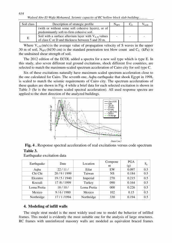
Six of these excitations naturally have maximum scaled spectrum acceleration close to the one calculated for Cairo. The seventh one, Aqba earthquake that shook Egypt in 1998, is scaled to match the seismic requirements of Cairo city. The spectrum accelerations of these quakes are shown in Fig. 4 while a brief data for each selected excitation is shown in Table 3 (Se is the maximum scaled spectral acceleration). All used response spectra are applied to the short direction of the analyzed buildings.
Fig. 4 . Response spectral acceleration of real excitations versus code spectrum
Table 3. Earthquake excitation data
Earthquake Date Location Compone
nt PGA
(g) Se
Aqba 22 / 11 / 1995
Eilat EW 0.097 0.569 Chi Chi 20 / 9 / 1999 Taiwan NS 0.184 0.573 Elcentro 19 / 5 / 1940 Imperial
Valley 270 0.215 0.5
81 Koceali 17 /8 / 1999 Turkey 090 0.164 0.540 Loma Pretia 18 / 10 /
1989 Loma Pretia 000 0.226 0.5
83 Mexico 9 / 6 / 1980 Mexico 102 0.15 0.533 Northridge 17 / 1 /1994 Northridge 330 0.194 0.597
4. Modeling of infill walls
The single strut model is the most widely used one to model the behavior of infilled frames. This model is evidently the most suitable one for the analysis of large structures. RC frames with unreinforced masonry walls are modeled as equivalent braced frames
635
JES, Assiut University, Faculty of Engineering, Vol. 42, No. 3, May2014, pp. 629–651
(EBF). In this modeling, the infill walls are replaced by "equivalent struts". A model for representing the brick infill panel by equivalent diagonal strut was proposed by Mainstone
[39] and widely used by many researchers. For this model, the strut area, eA , was given
using the following expressions:
twA ee (1)
224.0 )( 175.0 lhhwe (2)
where 4
4
)2( sin
icc
i
HIE
tE (3)
h and l are the height and length of the frame panel, respectively, Ec and Ei are the elastic moduli of the column and of the infill panel, respectively, t is the thickness of the
infill panel, is the angle with horizontal axis defining diagonal strut, Ic is the moment of inertia of the column and Hi is the height of the infill panel. The effect of the openings is estimated using the method proposed by Asteris [34]. The value of
ew in Eq. (2) of
Mainstone [39] is multiplied by the value of the reduction factor, because of the opening, represented by Asteris [34].
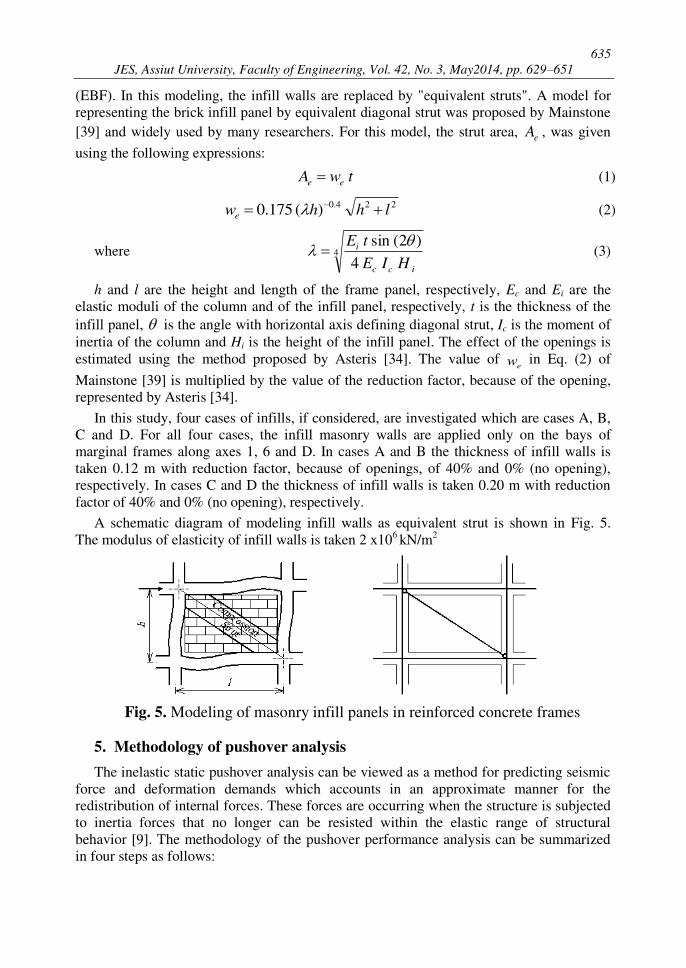
In this study, four cases of infills, if considered, are investigated which are cases A, B, C and D. For all four cases, the infill masonry walls are applied only on the bays of marginal frames along axes 1, 6 and D. In cases A and B the thickness of infill walls is taken 0.12 m with reduction factor, because of openings, of 40% and 0% (no opening), respectively. In cases C and D the thickness of infill walls is taken 0.20 m with reduction factor of 40% and 0% (no opening), respectively.
A schematic diagram of modeling infill walls as equivalent strut is shown in Fig. 5. The modulus of elasticity of infill walls is taken 2 x10⁶ kN/m2
Fig. 5. Modeling of masonry infill panels in reinforced concrete frames
5. Methodology of pushover analysis
The inelastic static pushover analysis can be viewed as a method for predicting seismic force and deformation demands which accounts in an approximate manner for the redistribution of internal forces. These forces are occurring when the structure is subjected to inertia forces that no longer can be resisted within the elastic range of structural behavior [9]. The methodology of the pushover performance analysis can be summarized in four steps as follows:
636
Waleed Abo El-Wafa Mohamed, Seismic capacity of RC hollow block slab building………
1- Idealizing the structure as a nonlinear model: A model of the entire structure is built from nonlinear representation of all of its elements and components.
2- Determining the capacity spectrum of the structure: The central focus of the simplified nonlinear procedure is the generation of the pushover or capacity curve. This represents the lateral displacement as a function of the force applied to the structure. This process is independent of the method used to calculate the demand and provide valuable insight about the building.
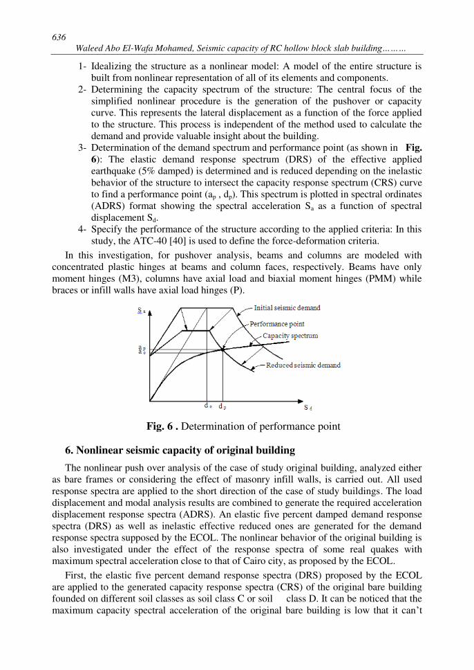
3- Determination of the demand spectrum and performance point (as shown in Fig.
6): The elastic demand response spectrum (DRS) of the effective applied earthquake (5% damped) is determined and is reduced depending on the inelastic behavior of the structure to intersect the capacity response spectrum (CRS) curve to find a performance point (ap , dp). This spectrum is plotted in spectral ordinates (ADRS) format showing the spectral acceleration Sa as a function of spectral displacement Sd.
4- Specify the performance of the structure according to the applied criteria: In this study, the ATC-40 [40] is used to define the force-deformation criteria.
In this investigation, for pushover analysis, beams and columns are modeled with concentrated plastic hinges at beams and column faces, respectively. Beams have only moment hinges (M3), columns have axial load and biaxial moment hinges (PMM) while braces or infill walls have axial load hinges (P).
Fig. 6 . Determination of performance point
6. Nonlinear seismic capacity of original building
The nonlinear push over analysis of the case of study original building, analyzed either as bare frames or considering the effect of masonry infill walls, is carried out. All used response spectra are applied to the short direction of the case of study buildings. The load displacement and modal analysis results are combined to generate the required acceleration displacement response spectra (ADRS). An elastic five percent damped demand response spectra (DRS) as well as inelastic effective reduced ones are generated for the demand response spectra supposed by the ECOL. The nonlinear behavior of the original building is also investigated under the effect of the response spectra of some real quakes with maximum spectral acceleration close to that of Cairo city, as proposed by the ECOL.
First, the elastic five percent demand response spectra (DRS) proposed by the ECOL are applied to the generated capacity response spectra (CRS) of the original bare building founded on different soil classes as soil class C or soil class D. It can be noticed that the maximum capacity spectral acceleration of the original bare building is low that it can’t
637
JES, Assiut University, Faculty of Engineering, Vol. 42, No. 3, May2014, pp. 629–651
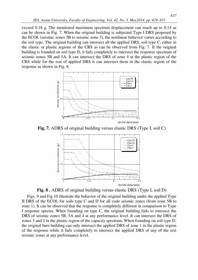
exceed 0.18 g. The monitored maximum spectrum displacement can reach up to 0.14 as can be shown in Fig. 7. When the original building is subjected Type I DRS proposed by the ECOL (seismic zones 5B to seismic zone 3), the nonlinear behavior varies according to the soil type. The original building can intersect all the applied DRS, soil type C, either in the elastic or plastic regions of the CRS as can be observed from Fig. 7. If the original building is founded on soil type D, it fails completely to intersect the response spectrum of seismic zones 5B and 5A. It can intersect the DRS of zone 4 at the plastic region of the CRS while for the rest of applied DRS it can intersect them in the elastic region of the response as shown in Fig. 8.
Fig. 7. ADRS of original building versus elastic DRS (Type I, soil C)
Fig. 8 . ADRS of original building versus elastic DRS (Type I, soil D)
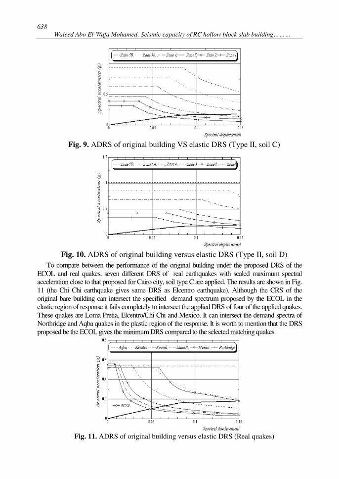
Figs. 9 and Fig.10 illustrate the behavior of the original building under the applied Type II DRS of the ECOL for soils type C and D for all code seismic zones (from zone 5B to zone 1). It can be observed that the response is completely different in comparison to Type I response spectra. When founding on type C, the original building fails to intersect the DRS of seismic zones 5B, 5A and 4 at any performance level. It can intersect the DRS of zones 3 and 2 in the plastic region of the capacity spectrum. When founding on soil type D, the original bare building can only intersect the applied DRS of zone 1 in the plastic region of the response while it fails completely to intersect the applied DRS of any of the rest seismic zones at any performance level.
638
Waleed Abo El-Wafa Mohamed, Seismic capacity of RC hollow block slab building………
Fig. 9. ADRS of original building VS elastic DRS (Type II, soil C)
Fig. 10. ADRS of original building versus elastic DRS (Type II, soil D)
To compare between the performance of the original building under the proposed DRS of the ECOL and real quakes, seven different DRS of real earthquakes with scaled maximum spectral acceleration close to that proposed for Cairo city, soil type C are applied. The results are shown in Fig. 11 (the Chi Chi earthquake gives same DRS as Elcentro earthquake). Although the CRS of the original bare building can intersect the specified demand spectrum proposed by the ECOL in the elastic region of response it fails completely to intersect the applied DRS of four of the applied quakes. These quakes are Loma Pretia, Elcentro/Chi Chi and Mexico. It can intersect the demand spectra of Northridge and Aqba quakes in the plastic region of the response. It is worth to mention that the DRS proposed be the ECOL gives the minimum DRS compared to the selected matching quakes.
Fig. 11. ADRS of original building versus elastic DRS (Real quakes)
639
JES, Assiut University, Faculty of Engineering, Vol. 42, No. 3, May2014, pp. 629–651
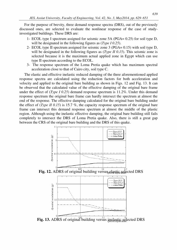
For the purpose of brevity, three demand response spectra (DRS), out of the previously discussed ones, are selected to evaluate the nonlinear response of the case of study-investigated buildings. These DRS are:
1- ECOL type I spectrum assigned for seismic zone 5A (PGA= 0.25) for soil type D, will be designated in the following figures as (Type I 0.25).
2- ECOL type II spectrum assigned for seismic zone 3 (PGA= 0.15) with soil type D, will be designated in the following figures as (Type II 0.15). This seismic zone is selected because it is the maximum actual applied zone in Egypt which can use type II spectrum according to the ECOL.
3- The response spectrum of the Loma Pretia quake which has maximum spectral acceleration close to that of Cairo city, soil type C.
The elastic and effective inelastic reduced damping of the three aforementioned applied response spectra are calculated using the reduction factors for both acceleration and velocity and applied to the original bare building as shown in Figs. 12 and Fig. 13. It can be observed that the calculated value of the effective damping of the original bare frame under the effect of (Type I 0.25) demand response spectrum is 11.2%. Under this demand response spectrum the original bare frame can hardly intersect the spectrum at almost the end of the response. The effective damping calculated for the original bare building under the effect of (Type II 0.15) is 15.7 %, the capacity response spectrum of the original bare frame can intersect this demand response spectrum at almost the middle of the plastic region. Although using the inelastic effective damping, the original bare building still fails completely to intersect the DRS of Loma Pretia quake. Also, there is still a great gap between the CRS of the original bare building and the DRS of this quake.
Fig. 12. ADRS of original building versus elastic selected DRS
Fig. 13. ADRS of original building versus inelastic selected DRS
640
Waleed Abo El-Wafa Mohamed, Seismic capacity of RC hollow block slab building………
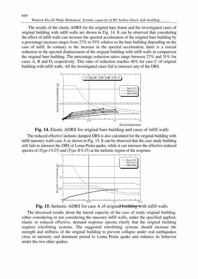
The results of the elastic ADRS for the original bare frame and the investigated cases of original building with infill walls are shown in Fig. 14. It can be observed that considering the effect of infill walls can increase the spectral acceleration of the original bare building by a percentage increase ranges from 27% to 93% relative to the bare building depending on the case of infill. In contrary to the increase in the spectral acceleration, there is a crucial reduction in the spectral displacement of the original building with infill walls in comparison the original bare building. The percentage reduction ratios range between 27% and 31% for cases A, B and D, respectively. This ratio of reduction reaches 46% for case C of original building with infill walls. All the investigated cases fail to intersect any of the DRS.
Fig. 14. Elastic ADRS for original bare building and cases of infill walls
The reduced effective inelastic damped DRS is also calculated for the original building with infill masonry walls case A as shown in Fig. 15. It can be observed that the case study building still fails to intersect the DRS of Loma Pretia quake, while it can intersect the effective reduced spectra of (Type I 0.25) and (Type II 0.15) at the inelastic region of the response.
Fig. 15. Inelastic ADRS for case A of original building with infill walls
The discussed results about the lateral capacity of the case of study original building, either considering or not considering the masonry infill walls, under the specified applied, elastic or reduced effective, demand response spectra clarify that the original building requires retrofitting systems. The suggested retrofitting systems should increase the strength and stiffness of the original building to prevent collapse under real earthquakes close in intensity and dominant period to Loma Pretia quake and enhance its behavior under the two other quakes.
641
JES, Assiut University, Faculty of Engineering, Vol. 42, No. 3, May2014, pp. 629–651
7. Retrofitting systems
In this study, the proposed and analyzed retrofitting systems are based on adding new simple technique to constitute a primary system for seismic resistance while keeping the existing building as a secondary system mainly responsible for carrying the gravity loads. A number of alternatives are available to afford the needed strength and stiffness to satisfy the needed performance characteristics. Some parameters are needed to be reviewed as desired performance level, the level of the disruption associated with each system and the access required to execute the required construction. Depending on this review, three different retrofitting systems are suggested and evaluated. A preliminary approach to design these systems using the nonlinear pushover analysis to find performance points within required deformation limit is carried out. The applied systems are briefly described as follows:
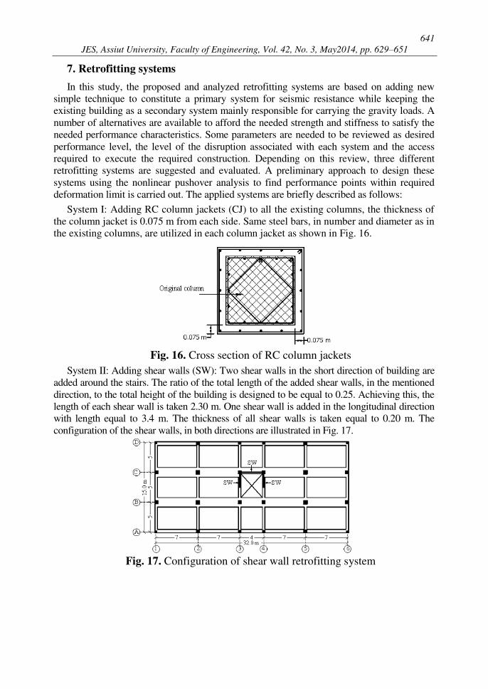
System I: Adding RC column jackets (CJ) to all the existing columns, the thickness of the column jacket is 0.075 m from each side. Same steel bars, in number and diameter as in the existing columns, are utilized in each column jacket as shown in Fig. 16.
Fig. 16. Cross section of RC column jackets
System II: Adding shear walls (SW): Two shear walls in the short direction of building are added around the stairs. The ratio of the total length of the added shear walls, in the mentioned direction, to the total height of the building is designed to be equal to 0.25. Achieving this, the length of each shear wall is taken 2.30 m. One shear wall is added in the longitudinal direction with length equal to 3.4 m. The thickness of all shear walls is taken equal to 0.20 m. The configuration of the shear walls, in both directions are illustrated in Fig. 17.
Fig. 17. Configuration of shear wall retrofitting system
642
Waleed Abo El-Wafa Mohamed, Seismic capacity of RC hollow block slab building………
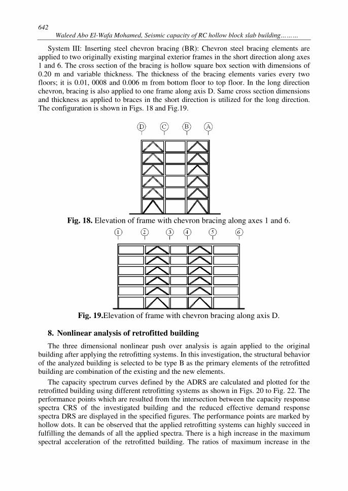
System III: Inserting steel chevron bracing (BR): Chevron steel bracing elements are applied to two originally existing marginal exterior frames in the short direction along axes 1 and 6. The cross section of the bracing is hollow square box section with dimensions of 0.20 m and variable thickness. The thickness of the bracing elements varies every two floors; it is 0.01, 0008 and 0.006 m from bottom floor to top floor. In the long direction chevron, bracing is also applied to one frame along axis D. Same cross section dimensions and thickness as applied to braces in the short direction is utilized for the long direction. The configuration is shown in Figs. 18 and Fig.19.
Fig. 18. Elevation of frame with chevron bracing along axes 1 and 6.
Fig. 19.Elevation of frame with chevron bracing along axis D.
8. Nonlinear analysis of retrofitted building
The three dimensional nonlinear push over analysis is again applied to the original building after applying the retrofitting systems. In this investigation, the structural behavior of the analyzed building is selected to be type B as the primary elements of the retrofitted building are combination of the existing and the new elements.
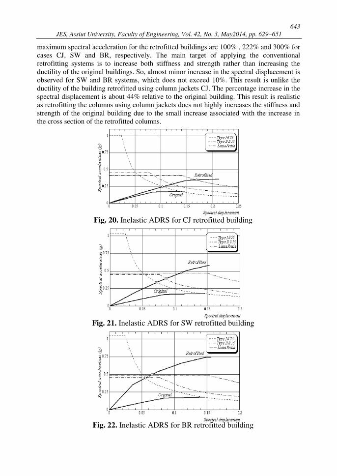
The capacity spectrum curves defined by the ADRS are calculated and plotted for the retrofitted building using different retrofitting systems as shown in Figs. 20 to Fig. 22. The performance points which are resulted from the intersection between the capacity response spectra CRS of the investigated building and the reduced effective demand response spectra DRS are displayed in the specified figures. The performance points are marked by hollow dots. It can be observed that the applied retrofitting systems can highly succeed in fulfilling the demands of all the applied spectra. There is a high increase in the maximum spectral acceleration of the retrofitted building. The ratios of maximum increase in the
643
JES, Assiut University, Faculty of Engineering, Vol. 42, No. 3, May2014, pp. 629–651
maximum spectral acceleration for the retrofitted buildings are 100% , 222% and 300% for cases CJ, SW and BR, respectively. The main target of applying the conventional retrofitting systems is to increase both stiffness and strength rather than increasing the ductility of the original buildings. So, almost minor increase in the spectral displacement is observed for SW and BR systems, which does not exceed 10%. This result is unlike the ductility of the building retrofitted using column jackets CJ. The percentage increase in the spectral displacement is about 44% relative to the original building. This result is realistic as retrofitting the columns using column jackets does not highly increases the stiffness and strength of the original building due to the small increase associated with the increase in the cross section of the retrofitted columns.
Fig. 20. Inelastic ADRS for CJ retrofitted building
Fig. 21. Inelastic ADRS for SW retrofitted building
Fig. 22. Inelastic ADRS for BR retrofitted building
644
Waleed Abo El-Wafa Mohamed, Seismic capacity of RC hollow block slab building………
From studying the resulting performance points of the retrofitted buildings, it is evident that although the original building fails completely to intersect the effective reduced DRS of the Loma Pertia earthquake in any performance point, the retrofitted buildings can intersect this demand response spectrum at reasonable points. The calculated performance points for the different proposed retrofitting systems are located in 80%, 73% and 50% of maximum spectral displacement of each response of CJ, SW and BR retrofitting systems, respectively. Regarding the rest two applied demand response spectra it can be observed that the performance points do not exceed 57% of the maximum spectral displacement of any of the response of the considered retrofitting systems. It is worth to mention that due to the high increase in the spectral acceleration associated with the BR systems, the performance points of the structure due to the three applied response spectra are very close.
The effective damping values associated with the applied reduced DRS are calculated for the original building and the retrofitted ones. These value are 11.9% and 15.7% for the original building under the two applied demand response spectra of the ECOL. For all the retrofitted buildings these values do not exceed 7.0 % for any of the mentioned two DRS. While there is no value can be calculated for the effective inelastic damping for the original building under the Loma Pretia DRS, the corresponding values for the different retrofitted systems were 10.9%, 7.8% and 7.1% for CJ, SW and BR, respectively. The mentioned values indicate that the retrofitting systems can mitigate the plasticity associated with the original building.
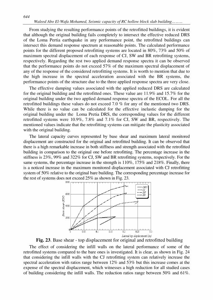
The lateral capacity curves represented by base shear and maximum lateral monitored displacement are constructed for the original and retrofitted building. It can be observed that there is a high remarkable increase in both stiffness and strength associated with the retrofitted building in comparison to the original one before retrofitting. The percentage increase in the stiffness is 23%, 99% and 322% for CJ, SW and BR retrofitting systems, respectively. For the same systems, the percentage increase in the strength is 110%, 175% and 218%. Finally, there is a noticed increase in the maximum monitored displacement associated with CJ retrofitting system of 50% relative to the original bare building. The corresponding percentage increase for the rest of systems does not exceed 25% as shown in Fig. 23.
Fig. 23. Base shear - top displacement for original and retrofitted building
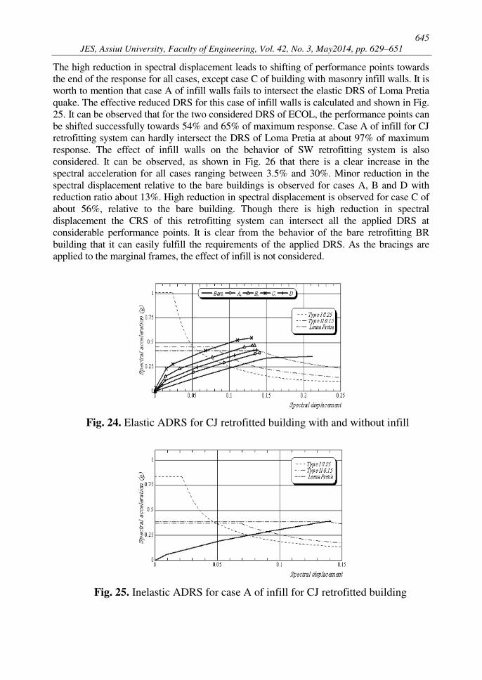
The effect of considering the infill walls on the lateral performance of some of the retrofitted systems compared to the bare ones is investigated. It is clear, as shown in Fig. 24 that considering the infill walls with the CJ retrofitting system can relatively increase the spectral acceleration with ratios range between 12% and 53% but this increase comes at the expense of the spectral displacement, which witnesses a high reduction for all studied cases of building considering the infill walls. The reduction ratios range between 50% and 61%.
645
JES, Assiut University, Faculty of Engineering, Vol. 42, No. 3, May2014, pp. 629–651
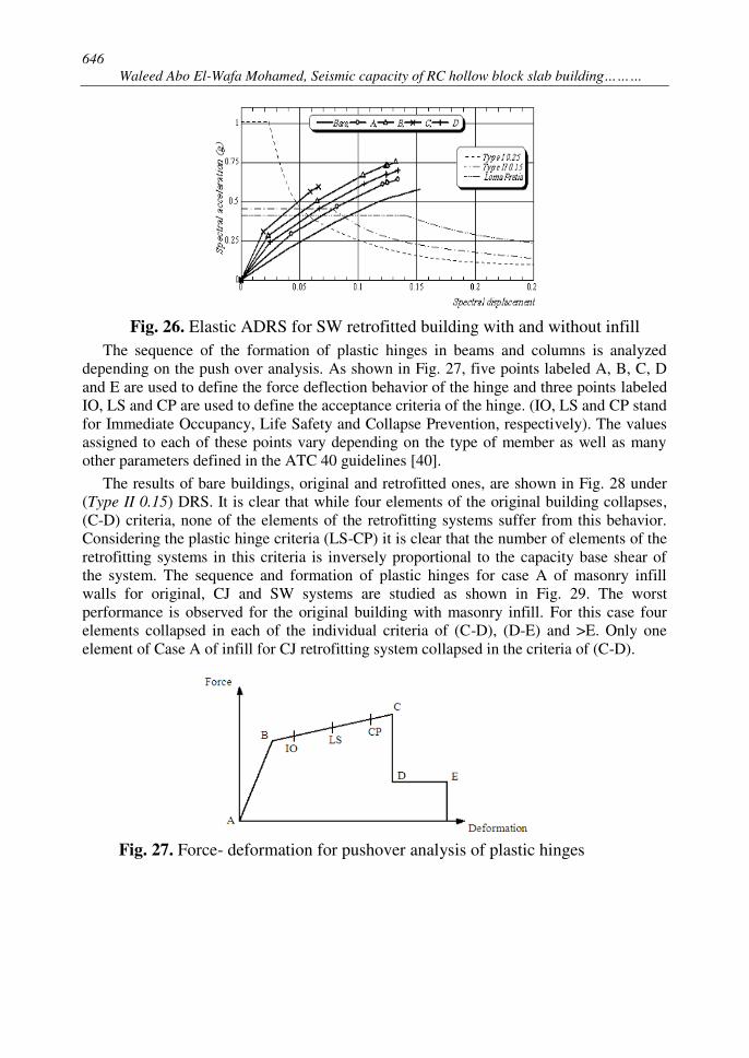
The high reduction in spectral displacement leads to shifting of performance points towards the end of the response for all cases, except case C of building with masonry infill walls. It is worth to mention that case A of infill walls fails to intersect the elastic DRS of Loma Pretia quake. The effective reduced DRS for this case of infill walls is calculated and shown in Fig. 25. It can be observed that for the two considered DRS of ECOL, the performance points can be shifted successfully towards 54% and 65% of maximum response. Case A of infill for CJ retrofitting system can hardly intersect the DRS of Loma Pretia at about 97% of maximum response. The effect of infill walls on the behavior of SW retrofitting system is also considered. It can be observed, as shown in Fig. 26 that there is a clear increase in the spectral acceleration for all cases ranging between 3.5% and 30%. Minor reduction in the spectral displacement relative to the bare buildings is observed for cases A, B and D with reduction ratio about 13%. High reduction in spectral displacement is observed for case C of about 56%, relative to the bare building. Though there is high reduction in spectral displacement the CRS of this retrofitting system can intersect all the applied DRS at considerable performance points. It is clear from the behavior of the bare retrofitting BR building that it can easily fulfill the requirements of the applied DRS. As the bracings are applied to the marginal frames, the effect of infill is not considered.
Fig. 24. Elastic ADRS for CJ retrofitted building with and without infill
Fig. 25. Inelastic ADRS for case A of infill for CJ retrofitted building
646
Waleed Abo El-Wafa Mohamed, Seismic capacity of RC hollow block slab building………
Fig. 26. Elastic ADRS for SW retrofitted building with and without infill
The sequence of the formation of plastic hinges in beams and columns is analyzed depending on the push over analysis. As shown in Fig. 27, five points labeled A, B, C, D and E are used to define the force deflection behavior of the hinge and three points labeled IO, LS and CP are used to define the acceptance criteria of the hinge. (IO, LS and CP stand for Immediate Occupancy, Life Safety and Collapse Prevention, respectively). The values assigned to each of these points vary depending on the type of member as well as many other parameters defined in the ATC 40 guidelines [40].
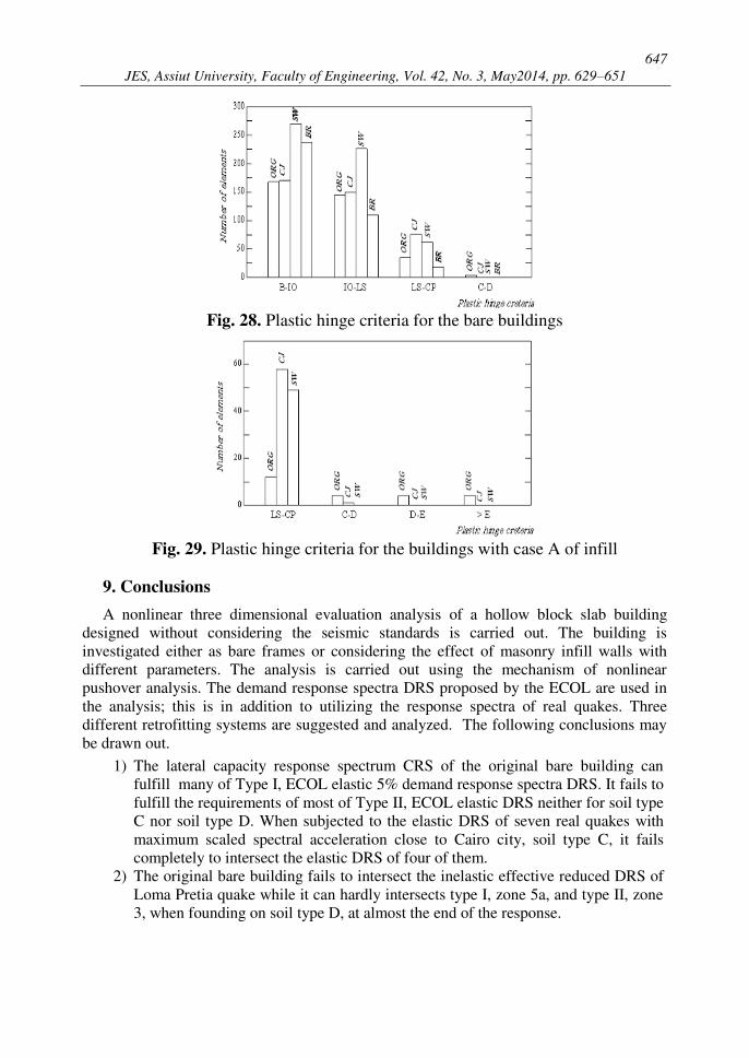
The results of bare buildings, original and retrofitted ones, are shown in Fig. 28 under (Type II 0.15) DRS. It is clear that while four elements of the original building collapses, (C-D) criteria, none of the elements of the retrofitting systems suffer from this behavior. Considering the plastic hinge criteria (LS-CP) it is clear that the number of elements of the retrofitting systems in this criteria is inversely proportional to the capacity base shear of the system. The sequence and formation of plastic hinges for case A of masonry infill walls for original, CJ and SW systems are studied as shown in Fig. 29. The worst performance is observed for the original building with masonry infill. For this case four elements collapsed in each of the individual criteria of (C-D), (D-E) and >E. Only one element of Case A of infill for CJ retrofitting system collapsed in the criteria of (C-D).
Fig. 27. Force- deformation for pushover analysis of plastic hinges
647
JES, Assiut University, Faculty of Engineering, Vol. 42, No. 3, May2014, pp. 629–651
Fig. 28. Plastic hinge criteria for the bare buildings
Fig. 29. Plastic hinge criteria for the buildings with case A of infill
9. Conclusions
A nonlinear three dimensional evaluation analysis of a hollow block slab building designed without considering the seismic standards is carried out. The building is investigated either as bare frames or considering the effect of masonry infill walls with different parameters. The analysis is carried out using the mechanism of nonlinear pushover analysis. The demand response spectra DRS proposed by the ECOL are used in the analysis; this is in addition to utilizing the response spectra of real quakes. Three different retrofitting systems are suggested and analyzed. The following conclusions may be drawn out.
1) The lateral capacity response spectrum CRS of the original bare building can fulfill many of Type I, ECOL elastic 5% demand response spectra DRS. It fails to fulfill the requirements of most of Type II, ECOL elastic DRS neither for soil type C nor soil type D. When subjected to the elastic DRS of seven real quakes with maximum scaled spectral acceleration close to Cairo city, soil type C, it fails completely to intersect the elastic DRS of four of them.
2) The original bare building fails to intersect the inelastic effective reduced DRS of Loma Pretia quake while it can hardly intersects type I, zone 5a, and type II, zone 3, when founding on soil type D, at almost the end of the response.
648
Waleed Abo El-Wafa Mohamed, Seismic capacity of RC hollow block slab building………
3) Considering the masonry infill walls in the analysis has a crucial effect on the results of the lateral capacity of the original building. There is a crucial reduction in the spectral displacement of the original building without retrofit reaches up to 46% of the maximum one. All the four analyzed cases of original building with infill walls fail to intersect any of the considered elastic DRS.
4) All the proposed retrofitting bare systems can succeed in highly enhancing the seismic capacity of the original building. High increase in strength and stiffness is associated with all the retrofitting systems.
5) The constructed ADRS of the proposed retrofitting systems under the considered inelastic DRS prove the efficient performance of all the proposed systems. Sufficient seismic performance levels are achieved for all the proposed systems under all the considered DRS.
6) The highest values of enhancing the seismic performance of the original building is observed for the retrofitting systems using steel chevron braces, followed by the internal shear walls and finally, strengthening the columns using reinforced concrete jackets.
7) The retrofitting systems can reduce the harmful effect which may arises from considering the masonry infill walls associated with the original infilled building due to the high increase in the strength and capacity acceleration relative to the bare building.
8) The comparison between the criteria of plastic hinges of all cases of the original and retrofitted buildings illustrates that all the retrofitting systems can almost eliminate the failure of elements associated with the original building, especially when considering the effect of infills.
9) Provisions about the procedures and accepted performance limits of non-seismic designed buildings and the considerations of masonry infill walls need to be presented by the Egyptian Codes.
REFERENCES
[1] Kyakula M, Behangana, N, Pario B. [2006] Comparative analysis of hollow clay block and soild reinforced concrete slabs. Proceedings from the International Conference on Advances
in Engineering and Technology: 84-90. [2] Watanabe E, Suglura K, Nagata K, Kitane Y. [1995] Performances and damages to steel structures
during the 1995 Hyogoken-Nanbu Earthquake. Engineering Structures; 20(4–6): 282–90. [3] Sevket A, Volkan K, Muhammet Y, Suleyman A. [2013] Damages on reinforced concrete
buildings due to consecutive earthquakes in Van. Engineering Structures; 53:109-118. [4] Ade L, Yoyong A. [2013] Lesson learned from 27th May 2006 Yogyakarta earthquake - Case
of building with long span of roof structure. Procedia Engineering; 54: 158 – 164. [5] Motosakaa M, Mitsujib Kazuya. [1995] Building damage during the 2011 off the Pacific
coast of Tohoku Earthquake. Soils and Foundations; 52(5):929–944. [6] Fukuyama H, Sugano S. [2000] Japanese seismic rehabilitation of concrete buildings after the
Hyogoken-Nanbu Earthquake. Cement & Concrete Composites; 22: 59 -79. [7] Garcia R, Hajirasouliha I, Pilakoutas K. [2010] Seismic behaviour of deficient RC frames
strengthened with CFRP composites. Engineering Structures; 32: 3075-3085 [8] Aydina E, Boduroglub M. [2008] Optimal placement of steel diagonal braces for upgrading
the seismic capacity of existing structures and its comparison with optimal dampers. Journal
of constructional steel research; 64: 72–86 [9] Ismail A. [2013] Non linear static analysis of a retrofitted reinforced concrete building,
HBRC Journal, article in press.
649
JES, Assiut University, Faculty of Engineering, Vol. 42, No. 3, May2014, pp. 629–651
[10] Hueste M, Bai J. [2007] Seismic retrofit of a reinforced concrete flat-slab structure: Part I-seismic performance evaluation. Engineering Structures; 29 :1165–1177.
[11] Rocha P, Delgado P, Costa A, Delgado R. [2004] Seismic retrofit of RC frames. Computers
and Structures; 82 : 1523–1534 [12] [1993] The Egyptian Code for Calculation of Loads and Forces in Structural and Building
Work. Housing and Building Research Center, Cairo, Egypt. [13] [2003] The Egyptian Code for Calculation of Loads and Forces in Structural and Building
Work, ECOL 201. Housing and Building Research Center, Cairo, Egypt. [14] [2008] The Egyptian Code for Calculation of Loads and Forces in Structural and Building
Work, ECOL 201. Housing and Building Research Center, Cairo, Egypt. [15] [2012] The Egyptian Code for Calculation of Loads and Forces in Structural and Building
Work, ECOL 201. Housing and Building Research Center, Cairo, Egypt. [16] Abo El-Wafa W. [2009] Level of seismic protection in different editions of the Egyptian code of
loads. Journal of Engineering Science, Assiut University; Vol. 37, No. 3: 1063-1079. [17] Abo El-Wafa W. [2009] Investigation on different lateral earthquake force methods of
analysis. Journal of Engineering Science, Assiut University, Journal of Engineering Science, Assiut University; Vol. 37, No. 3: 1081-1097.
[18] El-Sokkary H, Galal K [2009] Analytical investigation of the seismic performance of RC frames rehabilitated using different rehabilitation techniques. Engineering Structures; 31: 1955-1966
[19] Flanagan R, BennettR. [1999] In-plane behavior of structural clay tile infilled frames ” Journal of Structural Engineering, Vol. 125, No. 6: 590-599.
[20] Kormaz K, Demir F, Sivri M. [2007] Earthquake assessment of R/C structures with masonry infill walls. International Journal of Science & Technology, Volume 2, No. 2: 155-164.
[21] Kaushik H, Rai D, Jain S. [2006] Code approaches to seismic design of masonry-infilled reinforced concrete frames: A State-of-the-Art Review. Journal of Earthquake Spectra, Vol. 22: 961-983.
[22] Jain S, Mondral G. [2008] Lateral stiffness of masonry infilled reinforced concrete (RC) frames with central opening. Journal of Earthquake Spectra, Vol. 24: 701-723.
[23] Fajfar, P., Dolsek, M. [2001] Soft storey effects in uniformly infilled reinforced concrete frames ” Journal of Earthquake Engineering; Vol. 5: 1-12.
[24] Bayraktar A, Altunişik A, Pehlivan M. [2013] Performance and damages of reinforced concrete buildings during the October 23 and November 9, 2011 Van, Turkey, earthquakes. Soil Dynamics and Earthquake Engineering; 53: 49-72
[25] Toker S, Unay, I. [2006] Re-characterization of architectural style of reinforced concrete building facades by exterior seismic strengthening. Building and Environment, Vol. 41: 1952-1960.
[26] Tena-Colunga A, Verga A. [1997] Comparative study on the seismic retrofit of a mid-rise steel building: steel bracing vs energy dissipation" Earthquake Engineering and Structural
Dynamics; Vol. 26: 637-655. [27] Ghobarah A, Abou Elfath H. [2001] Rehabilitation of a reinforced concrete frame using
eccentric steel bracing. Engineering Structures; 23: 745–755. [28] Abo El-Wafa W. [2008] Seismic evaluation and retrofit of an asymmetric reinforced concrete flat
slab building. Journal of Engineering Sciences, Assiut University; Vol. 36, No. 2: 313-335. [29] Díaz J, Nieto P, Hernández J, Rabanal F. [2010] A FEM comparative analysis of the thermal
efficiency among floors made up of clay, concrete and lightweight concrete hollow block. Applied Thermal Engineering; 30: 2822-2826
[30] Jaime S, Mercedes D, Gemma C, Ignacio M, Dolores R. [2009] Fissure analysis in one-directional slabs with on-site concrete rib by continuous formwork. Construction and
Building Materials; 23: 2567–2579 [31] Smith, B. [1962] Lateral stiffness of infilled frames. Journal of Structural Division, Vol. 88,
No. 6: 183-199. [32] Al-Chaar G, Issa, M. [2002] Behavior of masonry-infilled nonductile reinforced concrete
650
Waleed Abo El-Wafa Mohamed, Seismic capacity of RC hollow block slab building………
frames. Journal of Structural Engineering, Vol. 128, No. 8:1055-1063. [33] Klingener R, Bertero, V. [1978] Earthquake resistance of infilled frames. Journal of
Structural Division, Vol. 104, No. 6: 973-989. [34] Asteris, P. [2003] Lateral stiffness of brick masonry infilled plane frames. Journal of
Structural Engineering; Vol. 129, No. 8: 1071-1079. [35] Sobaih, M, Abdin, M. [1988] Seismic analysis of infilled reinforced concrete frames.
Computer & Structures; Vol. 30, No. 3: 457 - 464. [36] Das D, Murty C. [2004] Brick masonry infills in seismic design of RC framed buildings: Part
1 - Cost implications” The Indian Concrete Journal: 39-43. [37] [2005] ETABS, Nonlinear version 9, Extended 3-D analysis of building systems Computers
and Structures, Inc., Berkeley, U.S.A. [38] [2003] Eurocode-8: Design of structures for earthquake resistance ” The European Committee
for Standardization, Final Draft, December 2003 [39] Mainstone R. [1974] Supplementary note on the stiffness and strength of infilled frames.
Building Research Station, Garston, Watford.

651
JES, Assiut University, Faculty of Engineering, Vol. 42, No. 3, May2014, pp. 629–651
السع الزلزالي لمبني خرساني مسلح ذو أسقف المناسبالباطا المفرغ ونظم التأهيل من
الملخص العربىةع ة الشة فرغ من اأن اط ال ف ال ا أس ست ء ب ر ن اإنش ة يةهفر مةن م ة ا فة يعت ل ل العة
ي را لكن ع ذا الن جهلع ن ه العرض ل را الع ق يكه الس سب الك عن تعرض غ ر منا الةة ا ةة يةة مةةن الةة ا التةة تعةةر لةةأح ا الع ل . تسةة نشةة العةة ا ماةة ا ل مةةن ال فةة ان ةة
ك الغ ر مص ط أكها ل الت ك مع ت ن رس ر ال ال يعت ه ال ل. اقتةرا ت ة السة الة ا الرأس من ط ط لأح ص ف ال لفعل ة ب ن ال حث نت ن تأه ل ل س ل . ال اأس
ن ه م ااس تح لت س حث فرغ ي هذا ال اط ال ف ال ن أس غ ر مص ط أي خرسااس ثاث أنأكها ل ال ن اأص . ت اقترا ا عن . لتأه ل ال ع ج ع هذ اأن ع ت
ح أ س ن ال رس ص ال ا اأق ست ء ااأع ب ن حهاةط قصنش ع أ اخ خرس ي ن ت من تا (Chevron)من النه الشك ست م طري التح ل. ت إجراء الت ب الاخط الثاث اأبع مست
فع صري (pushover analysis)ال ا ط ف التج ال من الكه ال ست ن ب ت التأث ر ع الف ت طق ال ل ال ال ن ا بنهع لج ع ال ا ط ف التج معلأح . ك ت است ف من الترب ت أنها م
هع من ال ا الح ج ن إم ل . ت تح ل ج ع ال هر ين ال سب ل ا ط ف تج أقص من ةص الا بأخذ تأث ر حهاةط الطه ك الص ف من الس ا هذا التأث ر. جه ت الفتح أ بإهن ةج أ ال ل التأه ل,ق ب نا النت كن من اأص , ق ع ل يت تط ال ل ال ل ل ء ب ل الهف ي من أط
ترح ع ال . نجحا أن الت صري أ ال ا الح ترح من الكه ال التج التص سهاء الن ه العرض ل ء تأث ر مص ري ع الس ن ن اأص . لحهاةط ال ه ال ل ال ل ف تحس ن الس
ا ف الح من هذا التأث ع تأث ر فع أن الت ر. اأص