Embed Size (px)
Citation preview
Seismic characteristics and distribution of volcanic intrusions and hydrothermal vent
complexes in the Vøring and Møre basins
S. PLANKE,1,2 T. RASMUSSEN,1 S. S. REY1 and R. MYKLEBUST3
1 Volcanic Basin Petroleum Research (VBPR), Oslo Research Park, 0349 Oslo, Norway
(e-mail: [email protected])2 Physics of Geological Processes, University of Oslo, PO Box 1048 Blindern, 0316 Oslo, Norway3 TGS-NOPEC, Baarsrudveien 2, 3478 Nærsnes, Norway
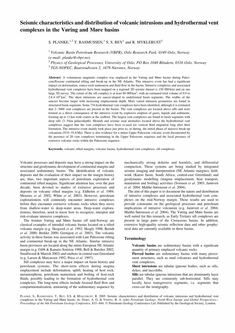
Abstract: A voluminous magmatic complex was emplaced in the Vøring and Møre basins during Paleo-
cene/Eocene continental rifting and break-up in the NE Atlantic. This intrusive event has had a significant
impact on deformation, source-rock maturation and fluid flow in the basins. Intrusive complexes and associated
hydrothermal vent complexes have been mapped on a regional 2D seismic dataset (c.150 000 km) and on one
large 3D survey. The extent of the sill complex is at least 80 000 km2, with an estimated total volume of 0.9 to
2.8 £ 104 km3. The sheet intrusions are saucer-shaped in undeformed basin segments. The widths of the
saucers become larger with increasing emplacement depth. More varied intrusion geometries are found in
structured basin segments. Some 734 hydrothermal vent complexes have been identified, although it is estimated
that 2–3000 vent complexes are present in the basins. The vent complexes are located above sills and were
formed as a direct consequence of the intrusive event by explosive eruption of gases, liquids and sediments,
forming up to 11 km wide craters at the seafloor. The largest vent complexes are found in basin segments with
deep sills (3–9 km palaeodepth). Mounds and seismic seep anomalies located above the hydrothermal vent
complexes suggest that the vent complexes have been re-used for vertical fluid migration long after their
formation. The intrusive event mainly took place just prior to, or during, the initial phase of massive break-up
volcanism (55.0–55.8 Ma). There is also evidence for a minor Upper Paleocene volcanic event documented by
the presence of 20 vent complexes terminating in the Upper Paleocene sequence and the local presence of
extrusive volcanic rocks within the Paleocene sequence.
Keywords: volcanic rifted margins, volcanic basins, hydrothermal vent complexes, sill complexes
Volcanic processes and deposits may have a strong impact on thestructure and geodynamic development of continental margins andassociated sedimentary basins. The identification of volcanicdeposits and the evaluation of their impact on the margin historyare, thus, two important aspects of petroleum exploration ofcontinental rifted margins. Significant attention has, over the pastdecade, been devoted to studies of extrusive processes anddeposits on volcanic rifted margins (e.g. Eldholm et al. 1989;Menzies et al. 2002; White et al. 2003). However, petroleumexplorationists will commonly encounter intrusive complexesbefore they encounter extrusive volcanic rocks when they movefrom shallow-water to deep-water areas. Deep-water explora-tionists, therefore, need to know how to recognize, interpret andrisk-evaluate intrusive complexes.
The frontier Vøring and Møre basins off mid-Norway areclassical examples of intruded volcanic basins located on a riftedvolcanic margin (e.g. Skogseid et al. 1992; Skogly 1998; Berndtet al. 2000; Brekke 2000; Gernigon et al. 2003). The volcanicactivity in these basins was associated with Late Paleocene riftingand continental break-up in the NE Atlantic. Similar intrusivebasin provinces are located along the entire European NE Atlanticmargin (e.g. Gibb & Kanaris-Sotiriou 1988; Bell & Butcher 2002;Smallwood & Maresh 2002) and onshore in central-east Greenland(e.g. Larsen & Marcussen 1992; Price et al. 1997).
Sill complexes may have a major impact on basin history andpetroleum systems. The short-term effects during magmaemplacement include deformation, uplift, heating of host rock,metamorphism, petroleum maturation and boiling of host-rockfluids, possibly leading to the formation of hydrothermal ventcomplexes. The long-term effects include focused fluid flow andcompartmentalization, armouring of the sedimentary sequence by
mechanically strong dolerite and hornfels, and differentialcompaction. These systems are being studied by integratedseismic imaging and interpretation (NE Atlantic margins), field-work (Karoo basin, South Africa; central-east Greenland) andgeodynamic modelling (magma emplacement, heat transport,maturation and boiling) activities (Svensen et al. 2003; Jamtveitet al. 2004; Malthe-Sørenssen et al. 2004).
The aim of this paper is to document the nature and distributionof intrusive complexes and associated hydrothermal vent com-plexes on the mid-Norway margin. These results are used toprovide constraints on the geological processes and petroleumimplications of intrusive volcanism (e.g. Jamtveit et al. 2004;Malthe-Sørenssen et al. 2004). The Vøring and Møre basins arewell suited for this research, as Early Tertiary sill complexes arepresent in large parts of the Cretaceous basins. In addition,extensive high-quality seismic reflection data and other geophy-sical data are currently available in these basins.
Terminology
Volcanic basins are sedimentary basins with a significantquantity of primary emplaced volcanic rocks.Pierced basins are sedimentary basins with many pierce-ment structures, such as mud volcanoes and hydrothermalvent complexes.Sheet intrusions are tabular igneous bodies, such as sills,dykes, and laccoliths.Sills are tabular igneous intrusions that are dominantly layerparallel. They are commonly sub-horizontal. Sills maylocally have transgressive segments, i.e. segments thatcross-cut the stratigraphy.
PLANKE, S., RASMUSSEN, T., REY, S.S. & MYKLEBUST, R. 2005. Seismic characteristics and distribution of volcanic intrusions and hydrothermal ventcomplexes in the Vøring and Møre basins. In: DORE, A. G. & VINING, B. A. (eds) Petroleum Geology: North-West Europe and Global Perspectives—Proceedings of the 6th Petroleum Geology Conference, 833–844. q Petroleum Geology Conferences Ltd. Published by the Geological Society, London.
Hydrothermal vent complexes are pipe-like complexes
formed by fracturing, transport and eruption of hydrothermal
fluids and sediments.
Data and method
Database
The project database consists of more than 1100 regional 2D
seismic profiles, with a length of c. 150 000 km and one 3D-cube
covering c. 2000 km2 (Fig. 1). In addition, high-pass filtered and
gridded high-quality ship-track gravity data and high-resolution
aeromagnetic data were available for most of the study area
(Planke & Myklebust 1999). Public-domain bathymetry (e.g.
IBCAO), satellite gravity (Sandwell & Smith 1997) and magnetic
data (Verhoef et al. 1996) were also used. Few wells are drilled in
the outer Vøring and Møre basins. Only one good well-tie to the
imaged sill complexes exists (6607/5-2; Fig. 2). Well 6607/12-1,
near the Nordland Ridge, was drilled through a hydrothermal vent
complex and a comprehensive analysis of this well has recently
been completed (e.g. Svensen et al. 2003). In addition, wells
6406/3-2, 6406/6-1, 6406/11-1, 6506/11-2 and 6507/2-1 were usedto calibrate the interpretations.
Method
Data integration and interpretation were mainly carried out in aseismic workstation environment. Most seismic profiles weredecimated and re-sampled to 8 ms to increase the computerperformance. 50 km to 100 km high-pass filtered gravity andaeromagnetic data were converted to pseudo-horizons and loadedinto the workstation software to facilitate qualitative integratedseismic–gravity–magnetic interpretation. Seismic modelling andre-processing activities and potential-field modelling studiescomplemented the qualitative interpretation.
Sill complex interpretation
Interpretation of sill intrusions differs from conventional methodsfor time horizon mapping. Sill interpretation requires determi-nation of lithology. Moreover, sill intrusions may split into severalunits or several units may merge into one unit. Sills can transgress
Fig. 1. Location map showing interpreted seismic database and structural framework. FFC, Fles Fault Complex; GR, Gjallar Ridge; MMH, Møre
Marginal High; NH, Nyk High; UH, Utgard High; VS, Vigrid Syncline; VMH, Vøring Marginal High. Inner limit of sill complex from this study. Volcanic
extrusive domains from Berndt et al. (2001); structural elements from Blystad et al. (1995).
S. PLANKE ET AL.834
(i.e. move up or down in the stratigraphy) and may contain holes.
In this study a combination of interpretation methods has beenused: (1) interpretation of sill reflections, (2) 3D voxel visualiza-tion, (3) seismic facies analysis; and (4) mapping of surfaces.
The following main criteria were used to interpret a seismicevent as a sill reflection: (1) high amplitude; (2) local transgres-
sion; (3) saucer-shape; and (4) abrupt terminations. A reflection isidentified as a possible sill reflection if it is a high-amplitude event.If the event transgresses, is saucer-shaped and/or terminates
abruptly, then the reflection is interpreted as a probable sillreflection. An event may also be interpreted as a sill reflectionif it can be correlated with interpreted sills on crossing profiles.
The reliability of the interpretation depends on how well the
criteria are satisfied. In addition, borehole calibration, magneticdata, 3D visualization geometries and pre-stack seismic analyseswere used to increase the reliability of the seismic interpretation.
An example of a sill complex interpreted by this method is shownin Figure 3. Note that only sill reflections interpreted with a high
reliability are used in this study and the mapping, thus, provides aconservative estimate of the sill distribution. All picked sillhorizons were merged and the shallowest sill at each location was
used to make a gridded surface.Sill complexes are well suited for 3D visualization methods
because of the high seismic amplitude and complex shape of the
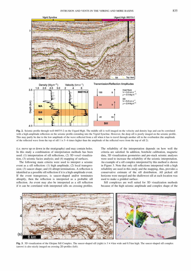
Fig. 2. Seismic profile through well 6607/5-2 on the Utgard High. The middle sill is well imaged on the velocity and density logs and can be correlated
with a high-amplitude reflection on the seismic profile extending into the Vigrid Syncline. However, the deep sill is poorly imaged on the seismic profile.
This may partly be due to the low amplitude of the wave reflected from a sill when it has to travel through another sill in the overburden (the amplitude
of the reflected wave from the top of sill 1 is 5–6 times higher than the amplitude of the reflected wave from the top of sill 2).
Fig. 3. 3D visualization of the Gleipne Sill Complex. The saucer-shaped sill (right) is 3 £ 4 km wide and 0.5 km high. The saucer-shaped sill complex
(arrow) is also nicely imaged on crossing 2D profiles (left).
INTRUSION AND VENTS IN THE VØRING AND MØRE BASINS 835
sill reflections (Fig. 3). However, the uppermost intrusions ofteninhibit deep imaging, making it difficult to visualize the entirecomplex. In this study, the software VoxelVision was used to studythe 3D aspects of the Gjallar and Gleipne sill complexes in theouter Vøring Basin.
Identified sill reflections were described and mapped using theconcept of seismic facies analysis, a method that was originallydescribed by Vail & Mitchum (1977). Seismic facies analysis isthe description and geological interpretation of seismic reflectionparameters, including configuration, continuity, frequency andinterval velocity. This method includes the definition and mappingof seismic facies units. A seismic facies unit is a mappable, three-dimensional group of seismic reflections, whose reflectionparameters differ from the adjacent facies units. The traditionaluse of seismic facies analysis is in sedimentary environments, butthe method is also used in volcanic environments (e.g. Planke et al.2000). Seismic facies analysis is also a suitable method formapping of sill intrusions (Skogly 1998), as the sills show a widerange of geometries and reflection parameters.
The seismic facies units (‘sill facies units’) were identified onthe seismic profiles and plotted on a map. The boundaries of the sillfacies units are not obvious in some cases, as diffuse boundariesand overlaps of facies units may occur. If overlapping sillreflections showed different seismic facies, then the dominatingfacies unit was plotted on the map. If facies units merged, thenthe limit between the facies units was put at the centre of thetransition zone.
Hydrothermal vent complexes
Two main intra-Tertiary horizons were interpreted regionallybased on seismic characteristics. These are the Top Vent and theTop Mound horizons. The Top Vent horizon was defined at keylocations where the upper part of the hydrothermal vent complexesis well defined (Figs 4 and 5). Care was taken to keep to the samestratigraphic level between the vent complexes. The Top Moundhorizon is characterized by small, mounded highs, seen as vertical
series of convex reflections and generally terminating at aconsistent stratigraphic level. The mounded highs are locatedabove the upper part of hydrothermal vent complexes or abovethe termination of deep-seated faults. The Top Mound horizonwas picked at a well-defined, laterally continuous trough at theuppermost part of the convex reflection package, where the moundshowed the greatest positive relief. The Top Mound horizon wassubsequently correlated between the well-defined picks. A consis-tent stratigraphic level was maintained throughout the interpre-tation. The Top Mound horizon is most distinct in the centralVøring Basin. Here, it is identified as a high-amplitude, continuousreflection defining the base of a generally low-amplitude sequencecharacterized by numerous, steep, small-offset normal faults. TheTop Mound horizon was not interpreted in the central and southernMøre Basin, as it is difficult to identify here. Finally, a Base VentHorizon was interpreted locally. Horizon and isochron maps weresubsequently generated and then high-pass filtered (25 and 50 kmcut-off frequencies).
The seismic characteristics of each interpreted hydrother-mal vent complex and the surrounding strata were entered into apseudo-well database. The following seismic features were inter-preted (Figs 4 and 5): (1) the geometry and size of the upper partof the vent complex (eye-, crater- or dome-shaped); (2) the natureof overlying reflections (mounded; high-amplitude events; distur-bed events); (3) the nature of underlying reflections (inward- andoutward-dipping events around the chimney; disrupted seismicdata; high-amplitude events); and (4) the presence and nature ofthe underlying sill complex.
The sill complex
Three sills were penetrated by well 6607/5-2 on the Utgard High(Fig. 2). The uppermost sill is a 2 m thick dolerite in lateCampanian claystones at a depth of 3419 m. A 91 m thick sill wasreached at a depth of 3792 m, intruded into altered claystones ofthe Campanian Shetland Group. The well terminated 50 m into athird sill below Turonian sandstones (Berndt et al. 2000). Sonic
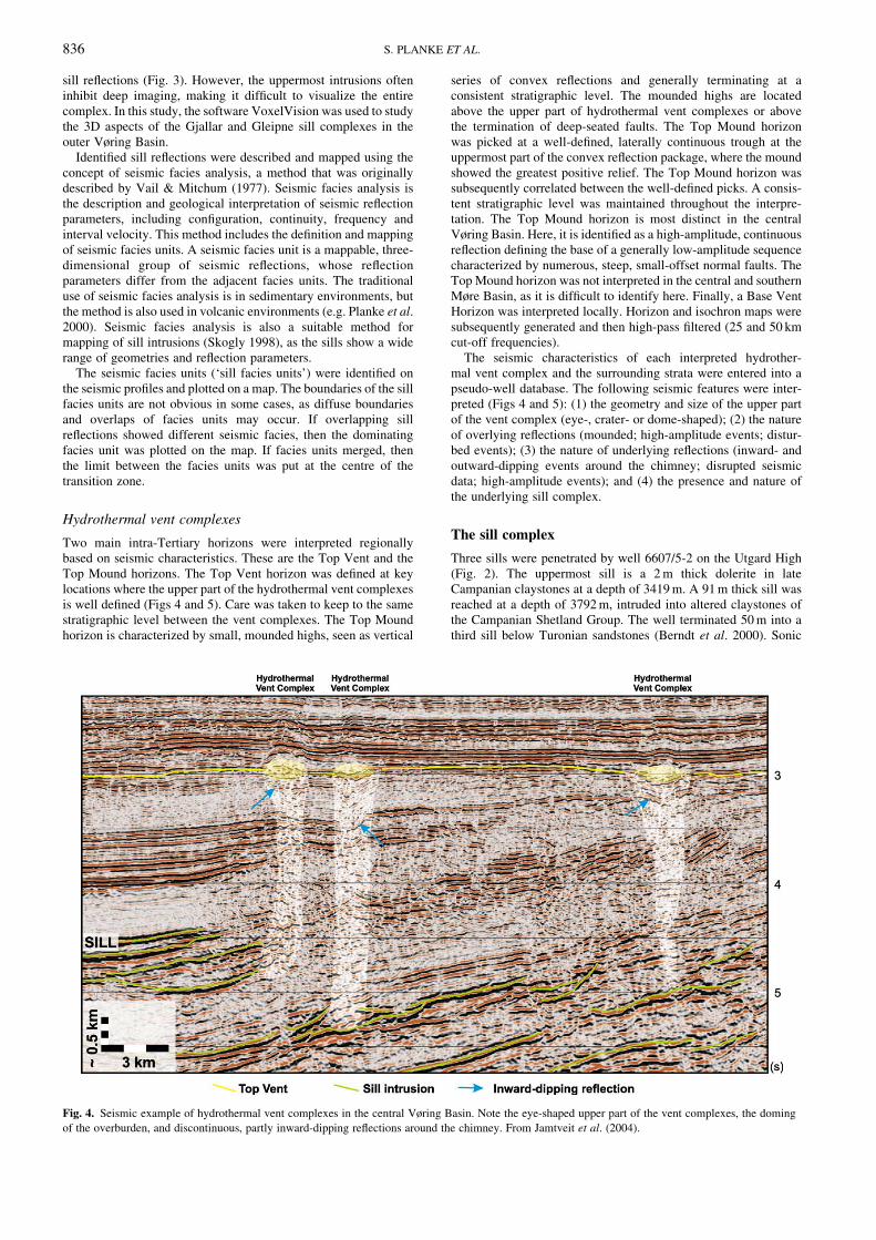
Fig. 4. Seismic example of hydrothermal vent complexes in the central Vøring Basin. Note the eye-shaped upper part of the vent complexes, the doming
of the overburden, and discontinuous, partly inward-dipping reflections around the chimney. From Jamtveit et al. (2004).
S. PLANKE ET AL.836
logs from the well show that the middle sill has an average velocity
of 7.0 km s21 (Fig. 2), which is very high compared with the
average sill p-wave velocity of 5.5 km s21 for .80 intrusions
drilled West of Shetland (Skogly 1998; Berndt et al. 2000). The
middle intrusion is clearly visible on a seismic section through the
well and can be correlated with a sill complex in the Vigrid
Syncline .100 km to the west (Fig. 2). The well provides a good
tie to the sill complexes in the Vøring Basin, and improves the
reliability of the seismic interpretation. Note that the upper and
lower sills drilled by well 6607/5-2 are not well imaged on the
seismic profile. The uppermost sill is too thin to be imaged. The
lowermost sill is probably poorly imaged due to large transmission
losses of reflected energy crossing the high-impedance boundaries
between the middle sill and the host rock four times (Fig. 2).
Sill intrusions have been interpreted regionally on the seismic
data in the Møre and Vøring basins. Two seismic type-profiles
across the central Møre Basin and the southern Vøring Basin are
shown in Figure 6. The intruded area has a width of 50–150 km
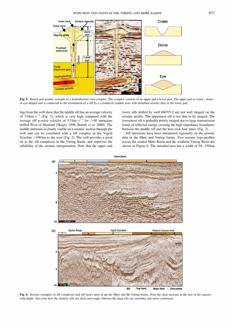
Fig. 5. Sketch and seismic example of a hydrothermal vent complex. The complex consists of an upper and a lower part. The upper part is crater-, dome-
or eye-shaped and is connected to the termination of a sill by a cylindrical conduit zone with disturbed seismic data in the lower part.
Fig. 6. Seismic examples of sill complexes and sill facies units in (a) the Møre and (b) Vøring basins. Note the clear increase in the size of the saucers
with depth. Also note how the shallow sills are short and rough, whereas the deep sills are smoother and more continuous.
INTRUSION AND VENTS IN THE VØRING AND MØRE BASINS 837
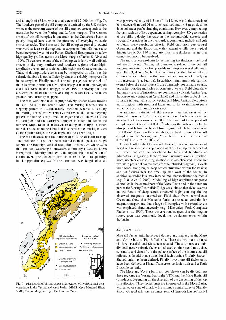
and a length of 65 km, with a total extent of 82 000 km2 (Fig. 7).The southern part of the sill complex is defined by the UK border,
whereas the northern extent of the sill complex corresponds to thetransition between the Vøring and Lofoten margins. The western
extent of the sill complex is uncertain as the Cretaceous basin is
poorly imaged here due to the presence of overlying volcanicextrusive rocks. The basin and the sill complex probably extend
westward at least to the regional escarpments, but sills have alsobeen interpreted west of the Faroe–Shetland Escarpment on a few
high-quality profiles across the Møre margin (Planke & Alvestad
1999). The eastern extent of the sill complex is fairly well defined,except in the very northern and southern regions where high-
amplitude events are associated with major pre-Cretaceous faults.These high-amplitude events can be interpreted as sills, but the
seismic database is not sufficiently dense to reliably interpret sillsin these regions. Finally, note that break-up-aged volcanic rocks of
the Vestbrona Formation have been dredged near the Norwegian
coast off Kristiansund (Bugge et al. 1980), showing that theeastward extent of the intrusive complexes can locally be much
greater than currently mapped.The sills were emplaced at progressively deeper levels toward
the east. Sills in the central Møre and Vøring basins show a
stepping pattern in a southeasterly direction, whereas sills alongthe Vøring Transform Margin (VTM) reveal the same stepping
pattern in a northeasterly direction (Figs 6 and 7). The width of thesill complex and the extrusive complex is much smaller in the
northern Møre Basin than elsewhere along the margin. Further,note that sills cannot be identified in several structural highs such
as the Gjallar Ridge, the Nyk High and the Utgard High.
The sill thickness and the number of sills are difficult to map.The thickness of a sill can be measured from the peak-to-trough
length. The Rayleigh vertical resolution limit is ld/4 where ld isthe dominant wavelength. However, commonly a ld/2 thickness
is required to identify confidently the top and bottom reflection of
a thin layer. The detection limit is more difficult to quantify,but is approximately ld/10. The dominant wavelength of a sill
with p-wave velocity of 5.5 km s21 is 183 m. A sill, thus, needs tobe between 46 m and 91 m to be resolved and .18 m thick to bedetected under perfect imaging conditions. However, complicatingfactors, such as offset-dependent tuning, complex 3D geometriesof the sills, velocity increase in the metamorphic aureole andstructural variations in the overburden, commonly make it difficultto obtain these resolution criteria. Field data from east-centralGreenland and the Karoo show that extensive sills have typicalthicknesses of 50–150 m and are, thus, in a thickness range thatcannot commonly be resolved.
The most severe problem for estimating the thickness and totalvolume of the mid-Norway sill complex is related to the sub-sillimaging problem. It is often possible to interpret several sill layers(e.g. Figs 3, 4 and 6), but the continuity of the deeper sills iscommonly lost when the thickness and/or number of overlyingsills increases (e.g. Fig. 6a). In addition, high-amplitude seismicevents below the uppermost sill are commonly not primary events,but rather peg-leg multiples or converted waves. Field data showthat many levels of intrusions are common in volcanic basins (e.g.the Karoo and central-east Greenland) and this is also probably thesituation in large parts of the Vøring and Møre basins. Exceptionsare in regions with structural highs and in the westernmost partswhen the deep sill complex dies out.
A minimum estimate of the average total thickness of theintruded basin is 100 m, whereas a more likely conservativeaverage thickness estimate is 300 m. The extent of the mapped sillcomplexes is at least 80 000 km2, whereas the sills are probablyalso present below the Inner Flows region, which has an area of13 000 km2. Based on these numbers, the total volume of the sillcomplex in the Vøring and Møre basins is in the order of0.9 £ 104 km3 to 2.8 £ 104 km3.
It is difficult to identify several phases of magma emplacementbased on the seismic interpretation of the sill complex. Individualsill reflections can be correlated for tens and hundreds ofkilometres, suggesting large-volume intrusive events. Further-more, no clear cross-cutting relationships are observed. There aretwo main potential source areas for the intruded magma: (1) weakfault zones along major deep-seated structures within the basins;and (2) fissures near the break-up axis west of the basins. Inaddition, extruded lava may intrude into unconsolidated sediments(e.g. Planke et al. 2000). Modelling of high-amplitude magneticanomalies in the central part of the Møre Basin and in the southernpart of the Vøring Basin (Ran Ridge area) shows that dyke swarmson the flanks of deep-seated structural highs can explain theobserved magnetic anomalies. Field data from central-eastGreenland show that Mesozoic faults are used as conduits formagma transport and that a large sill complex with several levelswas emplaced simultaneously (e.g. Manedalen Fault Complex;Planke et al. 1999). These observations suggest that the magmasource area was commonly local, i.e. weakness zones withinthe basin.
Sill facies units
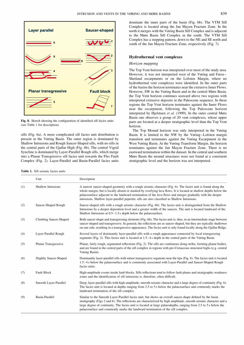
Nine sill facies units have been defined and mapped in the Møreand Vøring basins (Fig. 8; Table 1). There are two main groups:(1) layer parallel and (2) saucer-shaped. These groups are sub-divided into six seismic facies units based on the smoothness, size,continuity and depth from the palaeosurface of the interpreted sillreflections. In addition, a transitional facies unit, a Slightly Saucer-Shaped unit, has been defined. Finally, two more sill facies unitshave been defined, a Planar Transgressive facies unit and a FaultBlock facies unit.
The Møre and Vøring basin sill complexes can be divided intothree regions, the Vøring Basin, the VTM and the Møre Basin sillcomplexes, depending on the direction of the deepening of the topsill reflection. Three facies units are interpreted in the Møre Basin,with an outer zone of Shallow Intrusions, a central zone of SlightlySaucer-Shaped sills and an inner zone of Smooth Layer-Parallel
Fig. 7. Distribution of sill intrusions and location of hydrothermal vent
complexes in the Vøring and Møre basins. MMH, Møre Marginal High;
VMH, Vøring Marginal High; FZ, Fracture Zone.
S. PLANKE ET AL.838
sills (Fig. 6a). A more complicated sill facies unit distribution is
present in the Vøring Basin. The outer region is dominated by
Shallow Intrusions and Rough Saucer-Shaped sills, with no sills in
the central parts of the Gjallar High (Fig. 6b). The central Vigrid
Syncline is dominated by Layer-Parallel Rough sills, which merge
into a Planar Transgressive sill facies unit towards the Fles Fault
Complex (Fig. 2). Layer-Parallel and Basin-Parallel facies units
dominate the inner parts of the basin (Fig. 6b). The VTM SillComplex is located along the Jan Mayen Fracture Zone. In the
north it merges with the Vøring Basin Sill Complex and is adjacent
to the Møre Basin Sill Complex in the south. The VTM Sill
Complex has a stepping pattern, down to the NE and SE north andsouth of the Jan Mayen Fracture Zone, respectively (Fig. 7).
Hydrothermal vent complexes
Horizon mapping
The Top Vent horizon was interpreted over most of the study area.However, it was not interpreted west of the Vøring and Faroe–
Shetland escarpments or on the Lofoten Margin, where no
hydrothermal vent complexes were identified. In the outer parts
of the basins the horizon terminates near the extrusive Inner Flows.However, SW in the Vøring Basin and in the central Møre Basin,
the Top Vent horizon continues seaward above two regions with
interpreted extrusive deposits in the Paleocene sequence. In these
regions the Top Vent horizon terminates against the Inner Flowsnear the escarpment, following the Top Paleocene horizon
interpreted by Hjelstuen et al. (1999). In the outer central Møre
Basin one observes a group of 20 vent complexes, whose upper
parts are located at a deeper stratigraphic level than the Top Vent
horizon.The Top Mound horizon was only interpreted in the Vøring
Basin. It is limited to the NW by the Vøring–Lofoten margin
transition and terminates against the Vøring Escarpment in the
West Vøring Basin. At the Vøring Transform Margin, the horizonterminates against the Jan Mayen Fracture Zone. There is no
eastward termination within the dataset. In the central and southern
Møre Basin the mound structures were not found at a consistent
stratigraphic level and the horizon was not interpreted.
Table 1. Sill seismic facies units
Unit Description
(1) Shallow Intrusions A narrow saucer-shaped geometry with a rough seismic character (Fig. 6). The facies unit is found along the
whole margin, but is locally absent or masked by overlying lava flows. It is located at shallow depths below the
palaeosurface adjacent to the landward termination of the lava flows and merges gradually with the deeper
intrusions. Shallow layer-parallel peperitic sills are also classified as Shallow Intrusions.
(2) Saucer-Shaped Rough Saucer-shaped sills with a rough seismic character (Fig. 6b). The facies unit is distinguished from the Shallow
Intrusions by a deeper deposition level and a greater width of the saucers. The unit is located landward of the
Shallow Intrusions at 0.5–1.5 s depth below the palaeosurface.
(3) Climbing Saucer-Shaped Both saucer-shape and transgressing elements (Fig. 6b). The facies unit is, thus, in an intermediate stage between
saucer-shaped and transgressive. In general, the reflections are as saucer-shaped, but they are typically shallower
on one side, resulting in a transgressive appearance. The facies unit is only found locally along the Gjallar Ridge.
(4) Layer-Parallel Rough Several layers of dominantly layer-parallel sills with a rough appearance connected by local transgressing
segments (Fig. 2). This facies unit is located at 1.5–4 s depth in the central parts of the Vøring Basin.
(5) Planar Transgressive Planar, fairly rough, segmented reflections (Fig. 2). The sills are continuous along-strike, forming planar bodies,
and are found in the central parts of the sill complex in regions with pre-Cretaceous structural highs (e.g. central
Vøring Basin).
(6) Slightly Saucer-Shaped Dominantly layer-parallel sills with minor transgressive segments near the tips (Fig. 6). The facies unit is located
1.5–4 s below the palaeosurface and is commonly associated with Layer-Parallel and Saucer-Shaped Rough
facies units.
(7) Fault Block High-amplitude events inside fault blocks. Sills reflections tend to follow fault planes and stratigraphic weakness
zones and the identification of sill intrusions is, therefore, often difficult.
(8) Smooth Layer-Parallel Deep, layer-parallel sills with high-amplitude, smooth seismic character and a large degree of continuity (Fig. 6).
The facies unit is located at depths ranging from 2.5 to 5 s below the palaeosurface and commonly marks the
landward termination of the sill complex.
(9) Basin-Parallel Similar to the Smooth Layer-Parallel facies unit, but shows an overall saucer-shape defined by the basin
stratigraphy (Figs 2 and 6). The reflections are characterized by high amplitude, smooth seismic character and a
large degree of continuity. The facies unit is located at large palaeodepths, ranging from 2.5 to 5 s below the
palaeosurface and commonly marks the landward termination of the sill complex.
Fig. 8. Sketch showing the configuration of identified sill facies units
(see Table 1 for description).
INTRUSION AND VENTS IN THE VØRING AND MØRE BASINS 839
The Top Vent–Top Mound isochron map shows a margin-parallel NE–SW trend expressed by a thin sequence (0.0–0.3 s) inthe central and East Vøring Basin, flanked by thicker (0.4–0.8 s)areas along the western parts. There is a remarkable large, thin TopVent–Top Mound sequence (0.0–0.1 s) in the SW Vøring Basin,continuing SW to the Vøring Transform Margin. Locally, thinsequences are also located above structural highs, e.g. the GjallarRidge.
Vent complex statistics
In total, 734 vent complexes were identified in the Vøring andMøre basins (Table 2). The minimum and maximum diameters ofthe upper part of the vent complexes were 0.4 km and 11 km,respectively. The dominant diameter of the upper part of the ventcomplexes is 1–2 km, with an average of about 1.5 km. Theaverage diameter for the 2–5 km and .5 km vent complexes are3.5 km and 7.5 km, respectively. The total relief of the upper partof the vent complexes (Top Vent to Base Vent vertical distance)varies from 0.034 s to 0.50 s, with a mean of 0.13 s. Thiscorresponds to a thickness range of 30–450 m and a meanthickness of 120 m based on an average velocity of 1.8 km s21
derived from well 6607/12-1.Vent complexes are mainly located in the central and outer parts
of the basins. There is a marked difference in number of ventcomplexes between the Møre and Vøring basins, 133 and 601,respectively (Fig. 7). In general, small and intermediate ventcomplexes dominate the outer parts of the basins, whereas largevent complexes are found near the inner parts of the basins. Smallvent complexes represent more than 60% of all the identified vent
complexes and are also the most widespread. Large ventcomplexes (.5 km) constitute only 3.1% of the total number.
The eye-shaped upper parts dominate, whereas dome-shapedupper parts are also common (Table 2). No large dome-shapedvents were identified. Crater-shaped vents are most common in the
inner parts of the Vøring Basin, whereas only two craters havebeen identified in the Møre Basin.
Mounds are present in the Eocene and Oligocene sequencesabove the upper part of about 50% of the hydrothermal vent
complexes (Figs 9 and 10) and seismic seep anomalies (local high-amplitude events) are interpreted near the seafloor above about
25% of the vent complexes. Inward-dipping reflections arecommonly imaged around the conduit zone (about 40%), but
outward-dipping reflections are also found (about 10%).
Detectability of hydrothermal vent complexes
The total number of vent complexes formed in the Vøring andMøre basins is probably much higher than the 734 that have been
identified in this study. The identification of the vent complexesdepends on four main factors: (1) the seismic coverage; (2) the
diameter and thickness of the upper parts; (3) the quality of sub-basalt imaging; and (4) local removal of the upper part of the vent
complexes by erosion.Some 20% of the interpreted vent complexes were registered as
low quality, indicating that they do not have an easily identifiedupper part and/or are not associated with the most importantcharacteristic seismic anomalies. Five low-quality vent complexes
that were interpreted on the 2D lines are located within the 3Dcube area. These vent complexes are well defined on the 3D data.
The interpreted diameter of the upper part of the vent complexesis from 0.4 km to 11 km and the thickness range is 30 m to 450 m.
In general, a seismic line has to intersect the average-sized ventcomplex within 0.75–1 km from the centre to image the structure.
The line spacing of the interpreted 2D data is 1 km to 10 km. It isestimated that 2–10 times as many vent complexes as have beenidentified are present in the Vøring and Møre basins, i.e. 1500 to
7500, with three to five times the identified number as a reasonablerange. As a comparison, 15 of the 50 vent complexes that were
identified on the 3D data could be identified on the 2D data in thesame region.
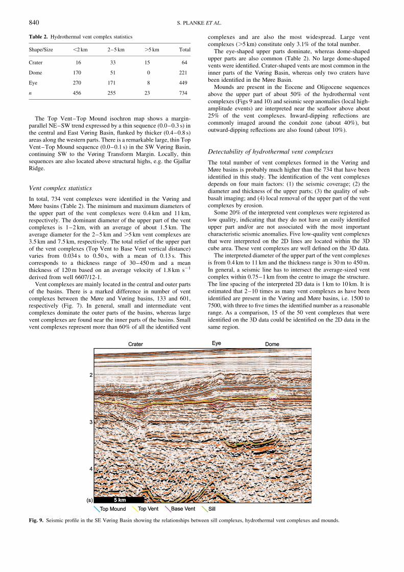
Table 2. Hydrothermal vent complex statistics
Shape/Size ,2 km 2–5 km .5 km Total
Crater 16 33 15 64
Dome 170 51 0 221
Eye 270 171 8 449
n 456 255 23 734
Fig. 9. Seismic profile in the SE Vøring Basin showing the relationships between sill complexes, hydrothermal vent complexes and mounds.
S. PLANKE ET AL.840
Vent complexes are probably also hidden beneath theseismically opaque extrusive volcanic rocks, in particular beneaththe seismically opaque Inner Flows. Erosion of the upper part ofthe vent complexes will make them difficult to detect and mayhave occurred locally in the Vøring and Møre basins (e.g. on theGjallar Ridge).
Distribution of sill and vent complexes
The seismic profiles show that the formation of hydrothermal ventcomplexes is closely related to the emplacement of sill intrusions(e.g. Figs 4 and 9). More than 50% of the hydrothermal ventcomplexes are located above the tip of a sill reflection. The map ofthe distribution of sill and hydrothermal vent complexes (Fig. 7)shows a well-defined spatial correlation between the presence ofsills and vent complexes. The mapping of the vent and sillcomplexes was done independently, but with seven exceptions allthe vent complexes are located in areas where sills are present.Inspection of seismic profiles shows that these seven ventcomplexes are most likely associated with local intrusions or justslightly offset from a deeper sill complex. No vent complexes wereobserved above the volcanic extrusive units (e.g. the Inner Flows).
Vent complexes and depth to sills
There is a general correlation between the size and geometry of theupper part of the vent complexes and the depth to the underlyingsill intrusion (Table 3). Small, dome-shaped upper parts have theshallowest mean depth to the underlying intrusions, whereas large,crater-shaped upper parts have the largest mean depth to theunderlying intrusions. However, it should be noted that there is a
fairly large scatter in the data, in particular between small and
intermediate size, and eye-shaped and dome-shaped upper parts.
However, on the 2D data one can only measure the apparent size of
the vent complexes and this measurement uncertainty may partly
explain the scatter.
Vent complexes and facies units
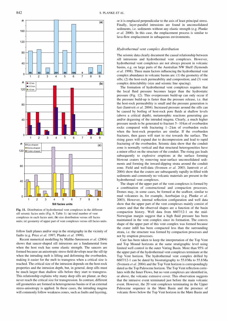
Figure 11 shows the distribution of the various types ofhydrothermal vent complexes in relation to the different sill facies
units. Sill facies units 1–3 are saucer-shaped sills located in the
outer parts of basins, sill facies units 4–6 are nearly planar
intrusions at intermediate depths located in the central parts of the
basins, whereas sill facies units 8 and 9 are deep, layer-parallel
sills, located in the inner parts of basins. Sill facies unit 7 consistsof structurally dependent intrusions.
Most small-sized vent complexes are located above relatively
shallow sills (units 1–6). Very few small vent complexes are
located above the deep Smooth Layer-Parallel (8) and Basin-
Parallel (9) sills. Intermediate-sized vent complexes are present inlarger quantities in the eastern part of the basins, i.e. above Smooth
Layer-Parallel (8) and Basin-Parallel (9) sills. Large vent
complexes are predominantly identified above Slightly Saucer-
Shaped (6) or deep Basin-Parallel (9) sills.
Crater-shaped vent complexes are most common in the Slightly
Saucer-Shaped (6), Transgressive (5) and Basin-Parallel (9) faciesunits. Dome-shaped vent complexes are frequently observed above
Shallow (1), Layer-Parallel Rough (4) and Slightly Saucer-Shaped
(6) facies units, but are rarely seen originating from Smooth Layer-
Parallel (8) or Basin-Parallel (9) ones. Eye-shaped vent complexes
are associated with all sill facies units, except from intruded FaultBlocks (7). They are most abundant above Saucer-Shaped Rough
(2), Layer-Parallel Rough (4), Transgressive (5) and Slightly
Saucer-Shaped (6) sill facies units.
Discussion
Sill geometries and emplacement
The seismic facies unit mapping of interpreted sill intrusions
reveals several systematic variations in shape and geometry of the
sill complexes. (1) Saucer-shaped sills are a fundamental form and
are most common in shallow-to-intermediate depths in unde-
formed basin segments. (2) The deepest parts of the basins are
characterized by layer-parallel intrusions. (3) Sill geometries arestrongly influenced by structures and heterogeneities such as fault
blocks, layering and deformed strata. Similar observations are also
common in the field. Saucer-shaped sills are common in the Karoo
basin in South Africa, whereas the deep part of the Karoo basin is
characterized by dominantly layer-parallel intrusions (e.g.Chevallier & Woodford 1999). In contrast, intrusions in the
faulted Mesozoic basins on the Triall Ø, east-central Greenland,
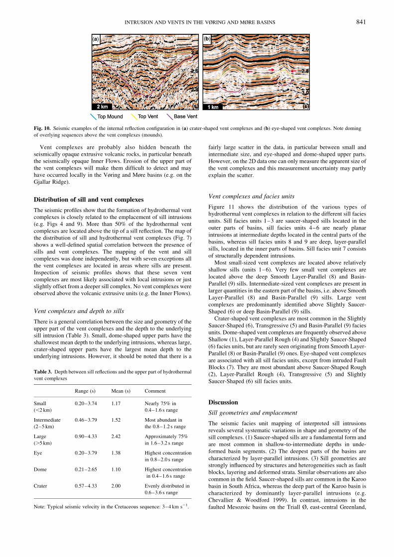
Fig. 10. Seismic examples of the internal reflection configuration in (a) crater-shaped vent complexes and (b) eye-shaped vent complexes. Note doming
of overlying sequences above the vent complexes (mounds).
Table 3. Depth between sill reflections and the upper part of hydrothermal
vent complexes
Range (s) Mean (s) Comment
Small
(,2 km)
0.20–3.74 1.17 Nearly 75% in
0.4–1.6 s range
Intermediate
(2–5 km)
0.46–3.79 1.52 Most abundant in
the 0.8–1.2 s range
Large
(.5 km)
0.90–4.33 2.42 Approximately 75%
in 1.6–3.2 s range
Eye 0.20–3.79 1.38 Highest concentration
in 0.8–2.0 s range
Dome 0.21–2.65 1.10 Highest concentration
in 0.4–1.6 s range
Crater 0.57–4.33 2.00 Evenly distributed in
0.6–3.6 s range
Note: Typical seismic velocity in the Cretaceous sequence: 3–4 km s21.
INTRUSION AND VENTS IN THE VØRING AND MØRE BASINS 841
follow fault planes and/or step in the stratigraphy in the vicinity of
faults (e.g. Price et al. 1997; Planke et al. 1999).
Recent numerical modelling by Malthe-Sørenssen et al. (2004)
shows that saucer-shaped sill intrusions are a fundamental form
when the host rock has some elastic strength. The saucers are
formed because an anisotropic stress-field develops near the sill tip
when the intruding melt is lifting and deforming the overburden,
making it easier for the melt to transgress when a critical size is
reached. The critical size of the intrusion depends on the host-rock
properties and the intrusion depth, but, in general, deep sills must
be much larger than shallow sills before they start to transgress.
This relationship explains why many deep sills are planar, as they
never reach the critical size for transgression. In contrast, different
sill geometries are formed in heterogeneous basins or if an external
stress-anisotropy is applied. In these cases, the intruding magma
will commonly follow weakness zones, such as faults and layering,
or it is emplaced perpendicular to the axis of least principal stress.Finally, layer-parallel intrusions are found in unconsolidated
sediments, i.e. sediments without any elastic strength (e.g. Planke
et al. 2000). In this case, the emplacement process is similar to
lava-flow emplacement in subaqueous environments.
Hydrothermal vent complex distribution
The seismic data clearly document the causal relationship between
sill intrusions and hydrothermal vent complexes. However,hydrothermal vent complexes are not always present in volcanic
basins, e.g. on large parts of the Australian NW Shelf (Symonds
et al. 1998). Three main factors influencing the hydrothermal vent
complex abundance in volcanic basins are: (1) the geometry of thesills; (2) the host-rock permeability and composition; and (3) vent
complex detectability (size and seismic line spacing).
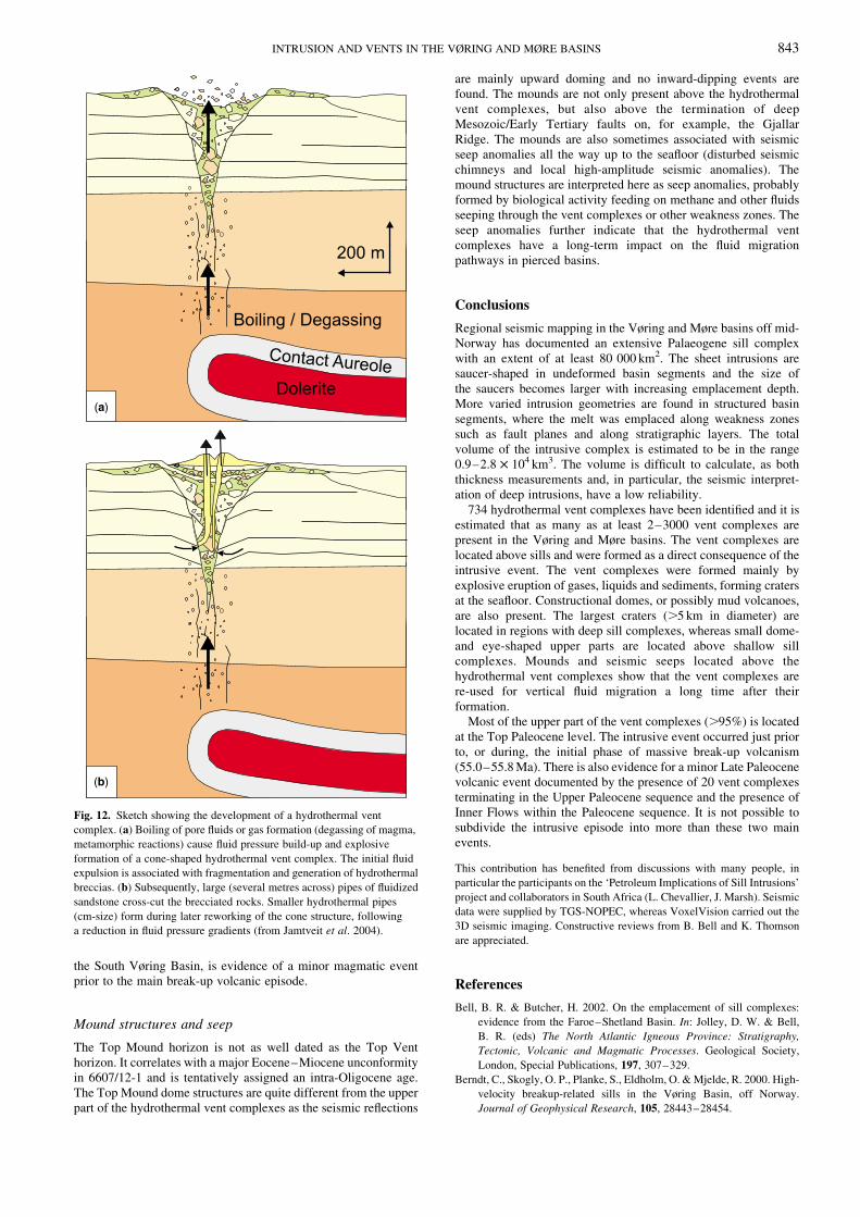
The formation of hydrothermal vent complexes requires that
the local fluid pressure becomes larger than the hydrostaticpressure (Fig. 12). This overpressure build-up can only occur if
the pressure build-up is faster than the pressure release, i.e. that
the host-rock permeability is small and the pressure generation is
fast (Jamtveit et al. 2004). Increased pressure around the sills can
be caused by boiling of host-rock pore fluids at shallow levels(above a critical depth), metamorphic reactions generating gas
and/or degassing of the intruded magma. Clearly, a much higher
pressure needs to be generated to fracture 5–10 km of overburden
rocks compared with fracturing 1–2 km of overburden rockswhen the host-rock properties are similar. If the overburden
fractures, then gases will start to rise towards the surface. The
rising gases will expand due to decompression and lead to rapid
fracturing of the overburden. Seismic data show that the conduitzone is normally vertical and that structural heterogeneities have
a minor effect on the structure of the conduit. The rising gas leads
subsequently to explosive eruptions at the surface forming
blowout craters by removing near-surface unconsolidated sedi-
ments and forming the inward-dipping strata around the conduitzone. Field and well-data (Svensen et al. 2003; Jamtveit et al.
2004) show that the craters are subsequently rapidly in-filled with
sediments and commonly no volcanic materials are present in the
hydrothermal vent complexes.The shape of the upper part of the vent complexes is formed by
a combination of constructional and compaction processes.
Domes may, in some cases, be formed at the seafloor, similar to
mud volcanoes in, for example, Azerbaijan (e.g. Planke et al.2003). However, internal reflection configuration and well data
show that the upper part of the vent complexes mainly consist of
craters and that the observed shapes are a function of the basin
compaction history. Well data from 6607/12-1 on the mid-
Norwegian margin suggest that a high fluid pressure has beenmaintained in the vent complex since its formation. The convex
shape of the upper part of this vent complex was formed because
the crater infill has been compacted less than the surrounding
strata, i.e. the structure was formed by compaction processes andnot by eruption processes.
Care has been taken to keep the interpretation of the Top Vent
and Top Mound horizons at the same stratigraphic level using
limited well control in the outer Vøring Basin. More than 95% of
the upper part of the hydrothermal vent complexes terminate at theTop Vent horizon. The hydrothermal vent complex drilled by
6607/12-1 can be dated by biostratigraphy to 55.0 Ma to 55.8 Ma
(Svensen et al. 2004) and the Top Vent horizon is correspondingly
dated as the Top Paleocene horizon. The Top Vent reflection corre-lates with the Inner Flows, but no vent complexes are identified in,
or above, the volcanic extrusive cover. This observation suggests
that the intrusive event terminated just before the main volcanic
event. However, the 20 vent complexes terminating in the UpperPaleocene sequence in the Møre Basin and the presence of
volcanic flows below the Top Vent horizon in the Møre Basin and
Fig. 11. Distribution of hydrothermal vent complexes in the different
sill seismic facies units (Fig. 8; Table 1): (a) total number of vent
complexes in each facies unit; (b) size distribution versus sill facies
units; (c) geometry of upper part of vent complexes versus sill facies units.
S. PLANKE ET AL.842
the South Vøring Basin, is evidence of a minor magmatic eventprior to the main break-up volcanic episode.
Mound structures and seep
The Top Mound horizon is not as well dated as the Top Venthorizon. It correlates with a major Eocene–Miocene unconformityin 6607/12-1 and is tentatively assigned an intra-Oligocene age.The Top Mound dome structures are quite different from the upperpart of the hydrothermal vent complexes as the seismic reflections
are mainly upward doming and no inward-dipping events arefound. The mounds are not only present above the hydrothermalvent complexes, but also above the termination of deepMesozoic/Early Tertiary faults on, for example, the GjallarRidge. The mounds are also sometimes associated with seismicseep anomalies all the way up to the seafloor (disturbed seismicchimneys and local high-amplitude seismic anomalies). Themound structures are interpreted here as seep anomalies, probablyformed by biological activity feeding on methane and other fluidsseeping through the vent complexes or other weakness zones. Theseep anomalies further indicate that the hydrothermal ventcomplexes have a long-term impact on the fluid migrationpathways in pierced basins.
Conclusions
Regional seismic mapping in the Vøring and Møre basins off mid-Norway has documented an extensive Palaeogene sill complexwith an extent of at least 80 000 km2. The sheet intrusions aresaucer-shaped in undeformed basin segments and the size ofthe saucers becomes larger with increasing emplacement depth.More varied intrusion geometries are found in structured basinsegments, where the melt was emplaced along weakness zonessuch as fault planes and along stratigraphic layers. The totalvolume of the intrusive complex is estimated to be in the range0.9–2.8 £ 104 km3. The volume is difficult to calculate, as boththickness measurements and, in particular, the seismic interpret-ation of deep intrusions, have a low reliability.
734 hydrothermal vent complexes have been identified and it isestimated that as many as at least 2–3000 vent complexes arepresent in the Vøring and Møre basins. The vent complexes arelocated above sills and were formed as a direct consequence of theintrusive event. The vent complexes were formed mainly byexplosive eruption of gases, liquids and sediments, forming cratersat the seafloor. Constructional domes, or possibly mud volcanoes,are also present. The largest craters (.5 km in diameter) arelocated in regions with deep sill complexes, whereas small dome-and eye-shaped upper parts are located above shallow sillcomplexes. Mounds and seismic seeps located above thehydrothermal vent complexes show that the vent complexes arere-used for vertical fluid migration a long time after theirformation.
Most of the upper part of the vent complexes (.95%) is locatedat the Top Paleocene level. The intrusive event occurred just priorto, or during, the initial phase of massive break-up volcanism(55.0–55.8 Ma). There is also evidence for a minor Late Paleocenevolcanic event documented by the presence of 20 vent complexesterminating in the Upper Paleocene sequence and the presence ofInner Flows within the Paleocene sequence. It is not possible tosubdivide the intrusive episode into more than these two mainevents.
This contribution has benefited from discussions with many people, in
particular the participants on the ‘Petroleum Implications of Sill Intrusions’
project and collaborators in South Africa (L. Chevallier, J. Marsh). Seismic
data were supplied by TGS-NOPEC, whereas VoxelVision carried out the
3D seismic imaging. Constructive reviews from B. Bell and K. Thomson
are appreciated.
References
Bell, B. R. & Butcher, H. 2002. On the emplacement of sill complexes:
evidence from the Faroe–Shetland Basin. In: Jolley, D. W. & Bell,
B. R. (eds) The North Atlantic Igneous Province: Stratigraphy,
Tectonic, Volcanic and Magmatic Processes. Geological Society,
London, Special Publications, 197, 307–329.
Berndt, C., Skogly, O. P., Planke, S., Eldholm, O. & Mjelde, R. 2000. High-
velocity breakup-related sills in the Vøring Basin, off Norway.
Journal of Geophysical Research, 105, 28443–28454.
Fig. 12. Sketch showing the development of a hydrothermal vent
complex. (a) Boiling of pore fluids or gas formation (degassing of magma,
metamorphic reactions) cause fluid pressure build-up and explosive
formation of a cone-shaped hydrothermal vent complex. The initial fluid
expulsion is associated with fragmentation and generation of hydrothermal
breccias. (b) Subsequently, large (several metres across) pipes of fluidized
sandstone cross-cut the brecciated rocks. Smaller hydrothermal pipes
(cm-size) form during later reworking of the cone structure, following
a reduction in fluid pressure gradients (from Jamtveit et al. 2004).
INTRUSION AND VENTS IN THE VØRING AND MØRE BASINS 843
Berndt, C., Planke, S., Alvestad, E., Tsikalas, F. & Rasmussen, R. 2001.
Seismic volcanostratigraphy of the Norwegian Margin: constraints on
tectonomagmatic break-up processes. Journal of the Geological
Society, London, 158, 413–426.
Blystad, P., Brekke, H., Færseth, R. B., Larsen, B., Skogseid, J. &
Tørudbakken, B. 1995. Structural elements of the Norwegian
continental shelf, Part II: The Norwegian Sea region. The Norwegian
NPD-bulletin 8, Petroleum Directorate.
Brekke, H. 2000. The tectonic evolution of the Norwegian Sea Continental
Margin with emphasis on the Vøring and Møre Basins. In: Nottvedt, A.
(ed.) Dynamics of the Norwegian Margin. Geological Society,
London, Special Publications, 167, 327–378.
Bugge, T., Prestvik, P. & Rokoengen, K. 1980. Lower Tertiary volcanic
rocks off Kristiansund, mid-Norway. Marine Geology, 35, 277–286.
Chevallier, L. & Woodford, A. 1999. Morpho-tectonics and mechanism of
emplacement of the dolerite rings and sills of the western Karoo,
South Africa. South African Journal of Geology, 102, 43–54.
Davis, R., Bell, B. R., Cartwright, J. A. & Shoulders, S. 2002. Three-
dimensional seismic imaging of Palaeogene dike-fed submarine vol-
canoes from the northeast Atlantic margin. Geology, 30, 223–226.
Eldholm, O., Thiede, J. & Taylor, E. 1989. Evolution of the Vøring
volcanic margin. ODP Scientific Results, 104, 1033–1065.
Gernigon, L., Ringenbach, J. C., Planke, S., Le Gall, B. & Jonquet-
Kolstø, H. 2003. Extension, crustal structure and magmatism at the
outer Vøring Basin, Norwegian margin. Journal of the Geological
Society, London, 160, 197–208.
Gibb, F. G. F. & Kanaris-Sotiriou, R. 1988. The geochemistry and origin
of the Faeroe–Shetland sill complex. In: Morton, A. C. & Parson,
L. M. (eds) Early Tertiary Volcanism and the Opening of the NE
Atlantic. Geological Society, London, Special Publications, 39,
241–252.
Hjelstuen, B., Eldholm, O. & Skogseid, J. 1999. Cenozoic evolution of the
northern Vøring margin. Geological Society of America Bulletin, 111,
1792–1807.
Jamtveit, B., Svensen, H., Podladchikov, Y. & Planke, S. 2004.
Hydrothermal vent complexes associated with sill intrusions in
sedimentary basins. In: Breitkreuz, C. & Petford, N. (eds) Physical
Geology of High-Level Magmatic Systems. Geological Society,
London, Special Publications, 234, 233–241.
Larsen, H. C. & Marcussen, C. 1992. Sill-intrusions, flood basalt
emplacement and deep crustal structure of the Scoresby Sund region,
East Greenland. In: Morton, A. C. & Parson, L. M. (eds) Early
Tertiary Volcanism and the Opening of the NE Atlantic. Geological
Society, London, Special Publications, 39, 95–114.
Malthe-Sørenssen, A., Planke, S., Svensen, H. & Jamtveit, B. 2004.
Formation of saucer-shaped sills. In: Breitkreuz, C. & Petford, N.
(eds) Physical Geology of High-Level Magmatic Systems. Geological
Society, London, Special Publications, 234, 215–227.
Menzies, M. A., Klemperer, S. L., Ebinger, C. J. & Baker, J. 2003.
Characteristics of volcanic rifted margins. Geological Society of
America, Special Paper, 362, 1–14.
Planke, S. & Alvestad, E. 1999. Seismic volcanostratigraphy of the
extrusive breakup complexes in the northeast Atlantic:
Implications from ODP/DSDP drilling. ODP Scientific Results,
163, 3–16.
Planke, S. & Myklebust, R. 1999. Nar seismikken kommer til kort. GEO,
Trondheim, 20–21.
Planke, S., Steen, Ø., Gisselø, P., Skogly, O. P. & Skogseid, J. 1999.
Outcrops on Traill Ø, East Greenland, guiding seismic interpretation
of sill complexes in Mesozoic basins in the NE Atlantic realm. In: The
role of geological fieldwork in hydrocarbon exploration and
production. CASP Publication, London, 56–57.
Planke, S., Symonds, P., Alvestad, E. & Skogseid, J. 2000. Seismic
volcanostratigraphy of large-volume basaltic extrusive complexes
on rifted margins. Journal of Geophysical Research, 105,
19335–19351.
Planke, S., Svensen, H., Hovland, M., Banks, D. A. & Jamtveit, B. 2003.
Mud and fluid migration in active mud volcanoes in Azerbaijan. Geo-
Marine Letters, 23, 258–268.
Price, S., Brodie, J., Whitham, A. & Kent, R. 1997. Mid-Tertiary rifting and
magmatism in the Triall Ø region, East Greenland. Journal of the
Geological Society, London, 154, 419–434.
Sandwell, D. T. & Smith, W. H. F. 1997. Marine gravity anomaly from
Geosat and ERS 1 satellite altimetry. Journal of Geophysical
Research, 102, 10039–10054.
Skogly, O. P. 1998. Seismic characterization and emplacement of
intrusives in the Vøring Basin PhD thesis, University of Oslo.
Skogseid, J., Pedersen, T., Eldholm, O. & Larsen, B. T. 1992. Tectonism
and magmatism during NE Atlantic continental break-up: the Vøring
Margin. In: Storey, B. C., Alabaster, T. & Pankhurt, R. J. (eds)
Magmatism and the Causes of Continental Break-up. Geological
Society, London, Special Publications, 68, 305–320.
Smallwood, J. & Maresh, J. 2002. The properties, morphology and
distribution of igneous sills: modeling, borehole data and 3D seismic
from the Faroe–Shetland area. In: The North Atlantic Igneous
Province: Stratigraphy, Tectonic, Volcanic and Magmatic Processes.
Geological Society, London, Special Publications, 197, 271–306.
Svensen, H., Jamtveit, B., Planke, S. & Pedersen, T. 2003. Seep carbonate
formation controlled by hydrothermal vent complexes: a case study
from the Vøring volcanic basin, the Norwegian Sea. Geo-Marine
Letters, 23, 351–358.
Svensen, H., Planke, S., Malthe-Sørenssen, A., Jamtveit, B., Myklebust, R.,
Rasmussen, T. & Rey, S. S. 2004. Explosive release of methane from
a volcanic basin as a mechanism for the initial Eocene global
warming. Nature, 429, 542–545.
Symonds, P. A., Planke, S., Frey, Ø. & Skogseid, J. 1998.
Volcanic development of the Western Australian continental margin
and its implications for basin development. In: Purcell, P. G. &
Purcell, R. R. (eds) The Sedimentary Basins of Western Australia 2:
Proceedings of Petroleum Exploration Society of Australia Sym-
posium, Perth, 33–54.
Vail, P. R. & Mitchum, R. M. 1977. Seismic stratigraphy and global
changes of sea level, 1, Overview. In: American Association of
Petroleum Geologists, Memoir, 26, 21–52.
Verhoef, J., Roest, R., Macnab, R. & Arkani-Hamad, J. 1996. Magnetic
anomalies of the arctic and North Atlantic oceans and adjacent land
areas. GSC Atlantic Open File 3125a, Dartmouth, Canada.
White, R. S., Smallwood, J. R., Fliedner, M. M., Boslaugh, B., Maresh, J.
& Fruehn, J. 2003. Imaging and regional distribution of basalt flows in
the Faeroe–Shetland basin. Geophysical Prospecting, 51, 215–231.
S. PLANKE ET AL.844
![Toward Forecasting Volcanic Eruptions using Seismic Noise ... · arXiv:0706.1935v1 [physics.geo-ph] 13 Jun 2007 Toward Forecasting Volcanic Eruptions using Seismic Noise Florent Brenguier,1,2∗](https://img.pdfslide.net/doc/110x75/5f65df0007692a29db660dda/toward-forecasting-volcanic-eruptions-using-seismic-noise-arxiv07061935v1.jpg)