Embed Size (px)
Citation preview
7/30/2019 Seismic Design of Reinforced Concrete Mat Foundations by Ron Klemencic Et Al, NIST GCR 12-917-22, 08-2012.
http://slidepdf.com/reader/full/seismic-design-of-reinforced-concrete-mat-foundations-by-ron-klemencic-et-al 1/33
NEHRP Seismic Design Technical Brief No. 7
Seismic Design of ReinforcedConcrete Mat Foundations
A Guide for Practicing Engineers
NIST GCR 12-917-22
Ron KlemencicIan S. McFarlaneNeil M. HawkinsSissy Nikolaou
7/30/2019 Seismic Design of Reinforced Concrete Mat Foundations by Ron Klemencic Et Al, NIST GCR 12-917-22, 08-2012.
http://slidepdf.com/reader/full/seismic-design-of-reinforced-concrete-mat-foundations-by-ron-klemencic-et-al 2/33
About The AuthorsRon Klemencic, P.E., S.E., is President of Magnusson Klemencic
Associates (MKA), a structural and civil engineering rm headquartered in
Seattle, Washington. Ron is an American Concrete Institute (ACI) Fellow
and serves on the ACI Board of Directors. He is a voting member of ACI
318, 318H, 318D, ITG 5, and 374. Ron is a former chairman of ACI 374
and was awarded the ACI 2010 Alfred E. Lindau Award. He recently
led the development and U.S. adoption of Performance-Based Seismic
Design methodology for high-rise structures.
Ian S. McFarlane, P.E., is a Senior Design Engineer at Magnusson
Klemencic Associates (MKA), a structural and civil engineering rm
headquartered in Seattle, Washington. He is the firm’s in-house
foundation design specialist, and has experience designing a number
of building types including high-rise residential towers, healthcare, and
ofce buildings.
Neil M. Hawkins, PhD, Dist. M. American Society of Civil Engineers, Hon.
M. ACI, Fellow Structural Engineering Institute, Fellow Portland CementInstitute, is Professor Emeritus of Civil and Environmental Engineering,
University of Illinois at Urbana-Champaign. He has served on the
Main Committee and the Seismic Code Committee of ASCE 7 since
2001. He has been a member of the Main Committee and the Seismic
Subcommittee of ACI 318 since 1995. He served on the Building Seismic
About the Review PanelThe contributions of the three review panelists for this publication are
gratefully acknowledged.
Gregg E. Brandow, PhD, P.E., S.E., is the former President of Brandow
& Johnston, Structural Engineers, in Los Angeles, California, where he
led the rm’s design of over 4,000 projects, including schools, hospitals,
and highrise buildings. He is now a Principal with Brandow & Nastar
and a Professor of Engineering Practice at the University of Southern
California. He has over 40 years of structural design experience,
earthquake reconnaissance opportunities, and forensic engineering. He
is active with SEI and ASCE and is Chair of the Structural Engineering
Licensure Coalition.
Viral B. Patel, P.E., S.E., is Senior Principal and Managing Director of the
Research and Development Group at Walter P. Moore and Associates
Inc., a National structural/civil engineering firm headquartered in
Houston, Texas. Mr. Patel is responsible for directing the Research &
Development group, which develops and disseminates standardized
resources, processes, and design tools to all Walter P Moore ofces
around the country. Mr. Patel also serves as consultant to senior project
managers on all major projects throughout the rm. He is a member of
ACI committees 375 and 314 and subcommittee 318-E.
James K. Wight, P.E., is the F.E. Richart, Jr. Collegiate Professor of Civil
Engineering at the University of Michigan. He is a Fellow of ASCE and
ACI. He is well-known nationally and internationally for his research in
earthquake-resistant design of concrete structures. Professor Wight
is the current President of the American Concrete Institute and haspreviously held several important positions including Chair of the ACI
Building Code Committee. He has received numerous awards for his
teaching and research including the ACI Joe Kelly Award, the C.P. Siess
Award for Excellence in Structural Research, and the Wason Medal for
the Most Meritorious Paper.
National Institute of
Standards and TechnologyNIST is a federal technology agency within the U.S. Department of
Commerce that promotes U.S. innovation and industrial competitiveness
by advancing measurement science, standards, and technology in ways
that enhance economic security and improve our quality of life. It is the
lead agency of the NEHRP. Dr. John (Jack) R. Hayes, Jr., is the Director
of NEHRP within NIST’s Engineering Laboratory (EL). Dr. Steven L.
McCabe managed the project to produce this Technical Brief for EL.
NEHRP Consultants Joint VentureThis NIST-funded publication is one of the products of the work of
the NEHRP Consultants Joint Venture carried out under Contract
SB134107CQ0019, Task Order 11175. The partners in the NEHRPConsultants Joint Venture are the Applied Technology Council (ATC) and
the Consortium of Universities for Research in Earthquake Engineering
(CUREE). The members of the Joint Venture Management Committee
are James R. Harris, Robert Reitherman, Christopher Rojahn, and
Andrew Whittaker, and the Program Manager is Jon A. Heintz.
NEHRP Seismic DesignTechnical BriefsNEHRP (National Earthquake Hazards Reduction Program) Technical
Briefs are published by NIST, the National Institute of Standards and
Technology, as aids to the efficient transfer of NEHRP and other
research into practice, thereby helping to reduce the nation’s losses
from earthquakes.
Safety Council (BSSC) Foundations and Concrete Subcommittees from
1987 through 2010 and on the BSSC Provisions Update Committee from
1997 through 2010.
Sissy Nikolaou, PhD, PE, is a Senior Associate at Mueser Rutledge
Consulting Engineers in New York City. She leads the rm’s geo-seismic
services, which have been key on design or retrot of several critical
projects, such as the Hillview Reservoir Cover, Columbia University’sManhattanville Campus, and the Queensboro and Woodrow Wilson
Bridges. She chairs the committee for the NYC Seismic Building Code.
Sissy has received the Shamsher Prakash award for Excellence in
Geotechnical Earthquake Engineering and was recently elected as
the rst President of the New York-Northeast regional Earthquake
Engineering Research Institute chapter.
Consortium of Universities for Research in
Earthquake Engineering (CUREE)
1301 South 46th Street - Building 420
Richmond, CA 94804
(510) 665-3529
www.curee.org email: [email protected]
Applied Technology Council (ATC)
201 Redwood Shores Parkway - Suite 240
Redwood City, California 94065
(650) 595-1542
www.atcouncil.org email: [email protected]
CUREE
7/30/2019 Seismic Design of Reinforced Concrete Mat Foundations by Ron Klemencic Et Al, NIST GCR 12-917-22, 08-2012.
http://slidepdf.com/reader/full/seismic-design-of-reinforced-concrete-mat-foundations-by-ron-klemencic-et-al 3/33
By
Ron Klemencic
Magnusson Klemencic Associates
Ian S. McFarlaneMagnusson Klemencic Associates
Neil M. HawkinsUniversity of Illinois, Urbana-Champaign
Sissy Nikolaou
Mueser Rutledge Consulting Engineers
August 2012
Prepared for
U.S. Department of Commerce
Engineering Laboratory
National Institute of Standards and TechnologyGaithersburg, MD 20899-8600
Seismic Design of ReinforcedConcrete Mat Foundations
A Guide for Practicing Engineers
NIST GCR 12-917-22
U.S. Department of Commerce
Rebecca M. Blank, Acting Secretary
National Institute of Standards and Technology
Patrick D. Gallagher, Under Secretary of Commerce for
Standards and Technology and Director
7/30/2019 Seismic Design of Reinforced Concrete Mat Foundations by Ron Klemencic Et Al, NIST GCR 12-917-22, 08-2012.
http://slidepdf.com/reader/full/seismic-design-of-reinforced-concrete-mat-foundations-by-ron-klemencic-et-al 4/33
DisclaimersThis Technical Brief was prepared for the Engineering Laboratory of the National Institute of Standards and Technology (NIST) under the
National Earthquake Hazards Reduction Program (NEHRP) Earthquake Structural and Engineering Research Contract SB134107CQ0019,Task Order 11175. The statements and conclusions contained herein are those of the authors and do not necessarily reect the views
and policies of NIST or the U.S. Government.
This report was produced by the NEHRP Consultants Joint Venture, a partnership of the Applied Technology Council (ATC) and theConsortium of Universities for Research in Earthquake Engineering (CUREE). While endeavoring to provide practical and accurate
information, the NEHRP Consultants Joint Venture, the authors, and the reviewers assume no liability for, nor express or imply any
warranty with regard to, the information contained herein. Users of the information contained in this report assume all liability arisingfrom such use.
The policy of NIST is to use the International System of Units (metric units) in all of its publications. However, in North America in theconstruction and building materials industry, certain non-SI units are so widely used instead of SI units that i t is more practical and lessconfusing to include measurement values for customary units only in this publication.
Cover photo – Mat foundation under construction.
How to Cite This PublicationKlemencic, Ron, McFarlane, Ian S., Hawkins, Neil M., and Nikolaou, Sissy (2012). “Seismic design of reinforced concrete mat foundations:
A guide for practicing engineers,” NEHRP Seismic Design Technical Brief No. 7 , produced by the NEHRP Consultants Joint Venture,a partnership of the Applied Technology Council and the Consortium of Universities for Research in Earthquake Engineering, for the
National Institute of Standards and Technology, Gaithersburg, MD, NIST GCR 12-917-22.
Introduction ..............................................................................................1
Historical Perspectives...............................................................................3
Soil Properties...........................................................................................6Soil-Structure Interaction............................................................................8
Load Combinations........................................................................ ..........11
Proportioning..........................................................................................14
Analysis..................................................................................................16
Design....................................................................................................18
Mats Supported on Deep Foundation Elements.............................................19
Detailing.................................................................................................20
Constructability Issues...............................................................................................22
References................................................................................................................24
Notation and Abbreviations.........................................................................................26Credits.......................................................................................................................29
1.
2.
3.4.
5.
6.
7.
8.
9.
10.
11.
12.
13.14.
Contents
7/30/2019 Seismic Design of Reinforced Concrete Mat Foundations by Ron Klemencic Et Al, NIST GCR 12-917-22, 08-2012.
http://slidepdf.com/reader/full/seismic-design-of-reinforced-concrete-mat-foundations-by-ron-klemencic-et-al 5/33
1
Seismic Design of Reinforced Concrete Mat Foundations: A Guide for Practicing Engineers
Seismic design of reinforced concrete mat foundations
has advanced significantly in the last twenty years. As
analytical capabilities have improved, primarily in the form
of nite element analysis, the mathematical modeling of these continuous structural elements has led to seemingly
more precise designs. Yet, fundamental questions still remain
regarding the seismic performance of these thick foundation
systems.
This Technical Brief attempts to address what is known
and what is unknown about this subject, so that a structural
engineer can proceed with a seismic design in an informed
manner. Because many of the parameters associated with a
mat foundation design can be highly variable, designs that
consider this variability are encouraged.
What is Known
Plate Mechanics. The mathematical modeling of continuous
mat foundations has been correlated with laboratory testing, providing condence that typical nite element modelingtechniques can offer a reasonable representation of the
performance of mat foundations.
Material Properties. Structural material properties of the
concrete and reinforcing steel that comprise reinforced mat
foundations are well dened and generally well documented.
What remains Unknown
Soil Properties. Despite thorough geotechnical investigations,
additional challenges in seismic mat foundation design are still
present, including properly identifying elastic dynamic soilproperties, quantifying strain-dependent soil behavior under
cyclic loading, and conducting sufcient in-situ and laboratorytesting to accurately capture the variability of the subsurface
conditions under the mat foundation.
Demand levels. Seismic demand levels dened by the currentapplicable building codes and standards in the United States
are not the same as the actual forces a mat foundation may
experience. Instead, demand levels are dened as inertialactions transferred by the super-structure considering
Response Modication Factors, R. This approach can call into
question the response of the foundation and the superstructure
as a whole, which can be particularly important for buildingsof signicant height or complexity.
Seismic Ground Motions. When seismic demands provided
in the codes and standards are not used and instead response
history analyses are performed, the uncertainties of the regional
hazard at the mat location should be considered. For large matfoundations, spatial variability of the ground motions in terms
of wave passage and soil effects should be considered.
1. Introduction
Build ing Codes and Standards
In this document, the following building codes
and standards are frequently referred to as thefollowing:
2012 edition of the International Building Code, IBC(2012), which provides the overall seismic and otherdesign requirements; referred to as IBC
2010 edition of Minimum Design Loads for Buildings and Other Structures , ASCE/SEI 7-10, ASCE (2010),which denes the criteria for seismic and other loads;
referred to as ASCE 7
2011 edition of Building Code Requirements for Structural Concrete , 318-11 American ConcreteInstitute, ACI (2011), which is the basic materials
standard that applies to reinforced concrete matfoundations; referred to as ACI 318
Older editions of these codes and standards maycurrently be the legal basis for design in various
jurisdictions in the United States, but toward the objectiveof making this Technical Brief a forward-looking guideand to keep it from quickly becoming outdated, the latesteditions listed above are used here. Structural designersneed to verify their locally applicable requirements anddiscuss design criteria with the building ofcials.
This Technical Brief, like companion ones in the NEHRP
Seismic Design Technical Brief series, goes beyondminimum codes and standards criteria to suggest bestpractices and areas where special investigations arerequired.
•
•
•
Shear. Traditionally, mat foundations have been propor tioned
based on local punching shear demands associated with column
loading. Global, one-way shear has not been well addressed
and can be particularly important in large mats subjected to
signicant over-turning demands from concrete core walls,shear walls, or braced frames. There are also some unknowns
regarding the transfer of overturning through exure and
punching shear from a wall to a mat foundation, as the ACI318 provisions that are applied in practice were developed for
slabs and columns.
Embedment of Reinforcing Steel. Current building code
provisions require only that vertical reinforcing steel be
developed for tension where moments and/or overturning
forces exist. This embedment length can be much smaller
than some very thick mat foundations, calling into question
7/30/2019 Seismic Design of Reinforced Concrete Mat Foundations by Ron Klemencic Et Al, NIST GCR 12-917-22, 08-2012.
http://slidepdf.com/reader/full/seismic-design-of-reinforced-concrete-mat-foundations-by-ron-klemencic-et-al 6/33
Seismic Design of Reinforced Concrete Mat Foundations: A Guide for Practicing Engineers
2
the activation of the entire mat section in resisting the imposed
forces.
Soil-Structure Interaction (SSI). Interaction of the structure
with the supporting soil can be idealized through numerical
modeling. These models can be tested for sensitivity to the
underlying assumptions regarding soil and structural stiffness.
Guidelines and standards for soil-structure interaction are still
being developed as discussed in NIST (2012).
This Technical Brief is organized to lead the reader through
the following sequence of topics:
• What is a Mat Foundation?
• Historical Perspectives
• Soil Properties
• Soil-Structure Interaction
• Load Combinations
• Proportioning
• Analysis
• Design
• Mats Supported on Deep Foundation Elements
• Detailing
• Constructability Issues
1.1 What is a Mat Foundation?
A reinforced concrete mat foundation is a common type of
foundation system used in many buildings. They are a specictype of shallow foundation that uses bearing capacity of the
soil at or near the building base to transmit the loads to the soil.
Compared to individual spread footings, a mat foundation may
encompass all or part of the building’s footprint. Compared to
an ordinary slab on grade, a reinforced concrete mat is much
thicker and is subjected to more substantial loads from the
building.
A mat foundation is often used where soil and load conditions
could cause substantial differential settlement between
individual spread footings but where conditions are not so
poor as to require a deep foundation system. For buildings
with signicant overturning moments, which can occur inregions of high seismicity or because of irregularities of
the superstructure, a mat foundation is commonly used to
distribute the bearing pressure over a large footprint and/or
to resist signicant uplift forces that can develop. Another frequent application for a mat foundation is where individual
spread footings would be large and close together. Similarly,
where many grade beam ties between footings are required, it
may not be economical to excavate and form individual spread
footings as compared to building a single mat foundation. For
a basement that is below the water table, a mat foundation is
often used to create a “bathtub” system to keep the basement
dry and to use the weight of the mat to resist hydrostatic uplift
forces. Where a mat is supported on deep foundation elements,
the mat also functions as the pile cap.
The behavior of a mat foundation can be correlated to a two-
way slab system turned upside down. The distributed soil
pressure applied to the bottom of the mat is analogous to adistributed slab load, and the columns and walls above the mat
become the supports for the mat foundation. Therefore, it is
common to apply analysis and design methods from two-way
slabs to a mat foundation.
The design forces, load combinations, and some analysis
requirements for a mat foundation are in ASCE7, which has been adopted into the IBC. In adopting ASCE7 provisions,IBC includes some modications and additions that will bediscussed later. As noted in the sidebar on the previous page,
IBC 2012 is the current version of this code but may not yet
be adopted by all jurisdictions; therefore, the governing code
should be conrmed for each particular project jurisdictionas appropriate. The design and detailing requirements for
a reinforced concrete mat foundation are presented in ACI
318, which has been adopted by the IBC as an incorporated
standard.
For concrete design, structural engineers predominatelyconsider ultimate strength design methods where the ultimate/
factored loading is compared to the member’s nominal strength.
This method has been incorporated into ACI 318 since the
1960s. However, geotechnical engineers predominatelyconsider allowable stress design, comparing service loads to
allowable stresses and soil bearing pressures. This fundamentaldifference must be understood and addressed when designing
a mat foundation. There is on-going development in building
code committees to codify ultimate strength design for
geotechnical engineers, but its use is not yet commonplace.
This issue of coordination between the structural engineer
and geotechnical engineer will be addressed in greater detail
throughout this Technical Brief.
Topics Beyond the Scope of this Document
Soil-structure interaction is only briey addressed in
this Technical Brief. For a complete discussion, refer
to NIST GCR 12-917-21 “Soil-Structure Interaction ofBuilding Structures” (NIST 2012).
The design of a mat foundation supporting tanks,
vessels, and other non-building structures is notaddressed in this Technical Brief.
Prestressed concrete is outside the scope of thisdocument.
7/30/2019 Seismic Design of Reinforced Concrete Mat Foundations by Ron Klemencic Et Al, NIST GCR 12-917-22, 08-2012.
http://slidepdf.com/reader/full/seismic-design-of-reinforced-concrete-mat-foundations-by-ron-klemencic-et-al 7/33
3
Seismic Design of Reinforced Concrete Mat Foundations: A Guide for Practicing Engineers
columns and walls, carrying the building weight as a load
assumed to be uniformly distributed over the soil. The
principles of reinforced concrete design were used to design
the mat with three types of mats recognized: at plates, beams with a slab underneath (like wafe slab construction),and beams with a slab on top. For plates, design for momentsand shears was based on the coefcients for at slab designspecied in the building code, with the slab thickness based onstiffness considerations and punching shears around columns
and walls. By theory, a perfectly rigid structure located on
an elastic subgrade has a minimum pressure near the center
and maximum pressure at the edge. Designs were prepared
assuming the ratio of the maximum to minimum pressure
was about two, and the two design conditions of both uniform
and varying soil pressures were used to proportion the mat.
Consequently, resulting designs called for providing more
reinforcement than that required by a more rigorous analysis.
In addition, it was common to provide the same amount of
reinforcement top and bottom in the mat. Where the primarydesign consideration was differential settlements resulting
from uneven column or wall loads and a compressible layer
or variations in the properties of the soil below the mat were
present, beams were often used to stiffen the mat.
The typical rule of thumb used for a mat on sand was, for
uniform loading, that the superstructure could tolerate a
differential settlement of about 0.75 inches between adjacentcolumns, with a maximum settlement of 2 inches overall.
For a mat on clay, the differential settlement was chiey dueto dishing and was roughly half the maximum settlement.
Dishing refers to the deected shape of the mat foundation.
However, the mat thickness was typically not greater than about0.01 times the radius of curvature, with some local increases
acceptable around columns and walls.
2.3 Basic Foundation Design Procedures
The existing procedures of ACI 318 for the design of mats
are based primarily on results of tests reported by Talbot
(1913), Richart (1948), and ACI-ASCE Committee 326 (1962,1974). The procedures effectively assume that foundations aredesigned using allowable stress for the soil and strength design
for the concrete foundation. Three limiting conditions were
assumed for the soil supporting the foundation: bearing failure
of the soil under the foundation, serviceability failure because
of excessive differential settlements causing nonstructural or
structural damage to the superstructure, and excessive total
settlements. Two limiting conditions must be considered
for the concrete foundation below the columns and walls of
the superstructure: local exural failure of the foundation(including reinforcement anchorage failure) and shear failure of
the foundation. The geotechnical engineer typically speciedan allowable soil bearing pressure, qa, a service load stress
2. Historic Perspectives
2.1 General
The design of mat foundations has long been recognized as
a problem in Soil-Structure Interaction that designers have
strived to simplify by designing mats that can be classied asrigid bodies. More recent requirements for earthquake-resistant
design have made that approach less appealing and have
increased the need for detailed considerations of soil-structure
interaction effects for mats. The increasing use of nite elementanalyses in the mid-1980s and subsequent increases in available
computing power have made such detailed considerations more
realistic and reliable. Hence, it is convenient to conne thishistorical perspective on mat foundation design to the body
of knowledge developed prior to the mid-1980s and to have
the remainder of this document address knowledge developed
since then as a result of detailed nite element analyses. Atapproximately the same time as computational capabilities
evolved signicantly, structural engineers adopted ultimate
strength design. Thus, the division of knowledge into thatexisting prior to the mid-1980s and that developed since is also
consistent with the timeline of two ACI 336 committee reports
(ACI Committee 336 1966, 1988) on foundation design. The
procedures of the 1966 report were repeatedly reafrmed untilthe publication of the second report in 1988. The 1988 report
has continued to be reapproved by ACI pending completion
of work on an updated document.
2.2 Early Designs
Mat foundations were originally envisaged as a floating
foundation with distinct advantages where the soil was poor or
unacceptable differential settlements were likely to occur. Earlywork showed that mats on sand (loose compacted, medium,
or dense) posed few problems. The factor of safety assumed
for such mats was twice that for an individual spread footing
and therefore no strength difculties were to be expected if the loading imposed on the mat by the superstructure was
effectively uniform. The allowable soil pressure was governed
by settlement and differential settlements between the walls
and columns supported by a mat. Typically, these allowable
soil bearing pressures were less than those for isolated footings
subject to the same loading.
By contrast, mats on clays had factors of safety against bearing
failures that were the same as those for footings and were
dependent on the length-to-width ratio of the mat or footing.
Otherwise the bearing strength was practically independent of
the area loaded by the mat or footing. Many of the initial uses
of mats were for large grain elevators and their performance
demonstrated those ndings.
A mat foundation was envisaged as a large combined footing
and designed as an inverted slab system spanning between
7/30/2019 Seismic Design of Reinforced Concrete Mat Foundations by Ron Klemencic Et Al, NIST GCR 12-917-22, 08-2012.
http://slidepdf.com/reader/full/seismic-design-of-reinforced-concrete-mat-foundations-by-ron-klemencic-et-al 8/33
7/30/2019 Seismic Design of Reinforced Concrete Mat Foundations by Ron Klemencic Et Al, NIST GCR 12-917-22, 08-2012.
http://slidepdf.com/reader/full/seismic-design-of-reinforced-concrete-mat-foundations-by-ron-klemencic-et-al 9/33
5
Seismic Design of Reinforced Concrete Mat Foundations: A Guide for Practicing Engineers
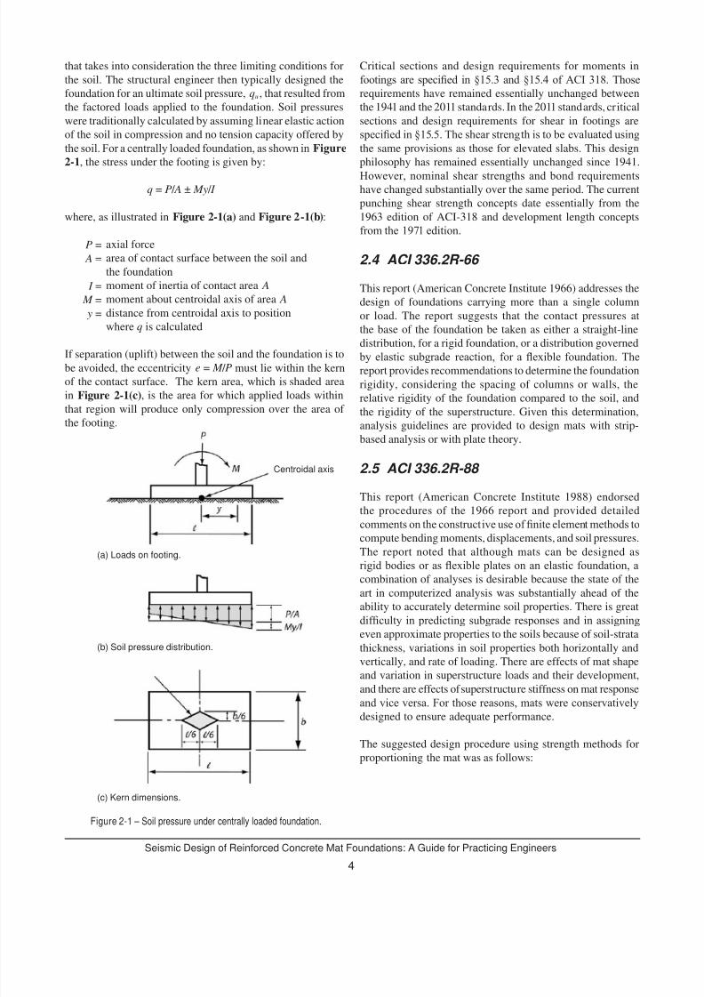
1. Proportion the mat plan using unfactored loads andoverturning moments as:
q = (1 ± (6e x / b) + (6e y / l ))
where the eccentricities e x and e y of the resultant column
loads ΣP include the effects of any column moments and any
overturning moments because of wind and other effects. The
value of q is required to be less than the allowable limiting soil
stress recommended by the geotechnical engineer. The value q
is then scaled to a pseudo “ultimate” value as:
qu = (sum of factored design loads/sum of
unfactored loads) . q
2. Compute the minimum required mat thickness based on
punching shear at critical columns and walls without the use
of shear reinforcement.
3. Design the reinforcing steel for bending based on the strip
methods described in the ACI 336.2R-66 report.
4. Run a computer analysis of the resultant mat, such as with
the nite element method as described in the ACI 336.2-88report. Revise the rigid body design as necessary.
2.6 Observations
The methods described in the ACI 336.2R-66 report oversimplify
behavior and result in designs that are too approximate for such
critical and expensive structural components. In addition, these
methods were not able to accurately predict settlement due to
the rigid versus exible behavior approximations.
The multiplication of the bearing pressure, q, by the pseudo
factor in the ACI 336.2R-88 report is of limited accuracy as the
value of q changes for each load combination. In addition, the
use of the pseudo factor could be considered a superposition of
results, which may not be appropriate for a nonlinear problem
such as a mat foundation resting on soil.
The foregoing procedures are all effectively based on assuming
mats of uniform thickness. It is often desirable to use mats with
thicknesses varying based on the loads acting on the local area
of the mat. Further, none of the prior committee reports haveaddressed the multiple issues related to the performance of mats
subjected to earthquake loads. Both the 1966 and 1988 reportspresented state-of-the-art techniques at the time of publication;
however, many of the methods described are now obsolete
due to the widespread use of three-dimensional nite elementanalysis software.
b l
ΣP
7/30/2019 Seismic Design of Reinforced Concrete Mat Foundations by Ron Klemencic Et Al, NIST GCR 12-917-22, 08-2012.
http://slidepdf.com/reader/full/seismic-design-of-reinforced-concrete-mat-foundations-by-ron-klemencic-et-al 10/33
Seismic Design of Reinforced Concrete Mat Foundations: A Guide for Practicing Engineers
6
3.1 Communication Between the Structural Engineer and Geotechnical Engineer
Critical to the appropriate design of any foundation system is
the clear and effective communication between the structuraland geotechnical engineers. Early discussions regarding themagnitude of acceptable building settlements and SSI effects
are important prior to the denition of soil parameters andstructural analysis and design techniques. Clarication of thegoverning code(s) and the consideration of seismic ground
motions are required as a starting point.
Items that should be discussed include the following:
Magnitude of acceptable differential and total settlements,
with sustained gravity loading as well as transient wind
and seismic demands being considered
Soil type, site category, and structural occupancy “or risk”
category
Details of any soil-structure interaction analysis to be
conducted
Approach to the structural modeling
Type of seismic analysis that will be performed (i.e., simple
base shear, response spectrum, or dynamic response history
analysis)
Denition of the assumed “seismic base” of the buildingfor dening the location and magnitude of input groundmotions
Elevation of mat, presence of any basement levels
Drainage issues
Presence of corrosive soils that may affect the concretemix specication
Existing adjacent structures, or substructure (such astunnels), that could interact with the mat
3.2 Parameters Needed From the Geotechnical Engineer
To design a mat foundation, the geotechnical engineer will
need to provide the following parameters to the structural
engineer:
Site Class
Design response spectrum
Allowable bearing pressure for static loads (indicating gross
or net bearing pressures) and the assumed factor of safety
Allowable bearing pressure for transient loads (wind or
seismic) and the assumed factor of safety
Subgrade modulus for both static and transient loadings(uniform or variable under the mat)
Mat foundation spring and dashpots for static and dynamic
conditions
Anticipated total and differential settlements
Passive soil resistance and friction coefcients for slidingcalculations and the assumed factors of safety
Guidance on how to adjust unit subgrade moduli for the size
of the mat and on how to use an interative process to account
for consolidation settlement of clays from sustained loads
Response histories, where applicable for input in the
structural model
Spatial variability of the seismic motions
This list includes only the parameters necessary to complete
the mat foundation design. The rst iteration of parametersshould be made based on an analysis assuming a xed basecondition foundation, which would be the upper bound of
the solution. In addition to this information, the geotechnical
engineer will need to provide information to produce complete
construction documents, such as subgrade preparation and
drainage requirements.
3.3 Denition of Soil Parameters
3.3.1 Allowable Soil Bearing Pressures
Traditionally, the starting point in designing the mat foundation
is setting an allowable soil bearing pressure. Currently,
prescriptive codes provide recommendations for allowable soil
bearing pressures for example, AASHTO (2010), based on thegeneric soil type. These values were developed for static load
conditions and could be increased by at least a factor of 2 for
the transient nature of the seismic loading within limits set by
the local governing codes. Alternatively, an allowable bearingpressure for mats can be derived based on expected performance
in terms of limiting settlements or other key performance
indexes as those are dened by the project objectives under long-term and seismic loading.
3.3.2 Subgrade Parameters
Until recent years, the modeling of the subgrade has relied on
the conventional parameter called the modulus of subgrade
reaction, usually expressed in a force per volume parameter
3. Soil Properties
•
•
•
•
•
•
•
•
•
•
•
•
•
•
•
•
•
•
•
•
•
7/30/2019 Seismic Design of Reinforced Concrete Mat Foundations by Ron Klemencic Et Al, NIST GCR 12-917-22, 08-2012.
http://slidepdf.com/reader/full/seismic-design-of-reinforced-concrete-mat-foundations-by-ron-klemencic-et-al 11/33
7/30/2019 Seismic Design of Reinforced Concrete Mat Foundations by Ron Klemencic Et Al, NIST GCR 12-917-22, 08-2012.
http://slidepdf.com/reader/full/seismic-design-of-reinforced-concrete-mat-foundations-by-ron-klemencic-et-al 12/33
Seismic Design of Reinforced Concrete Mat Foundations: A Guide for Practicing Engineers
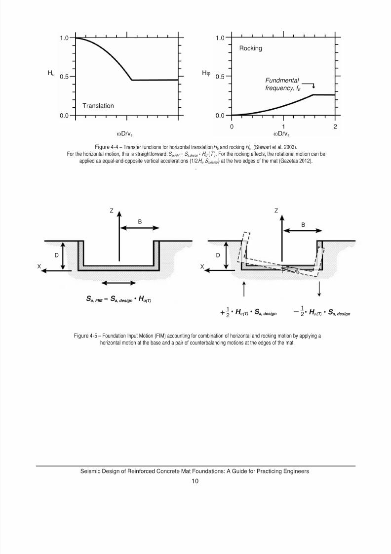
8
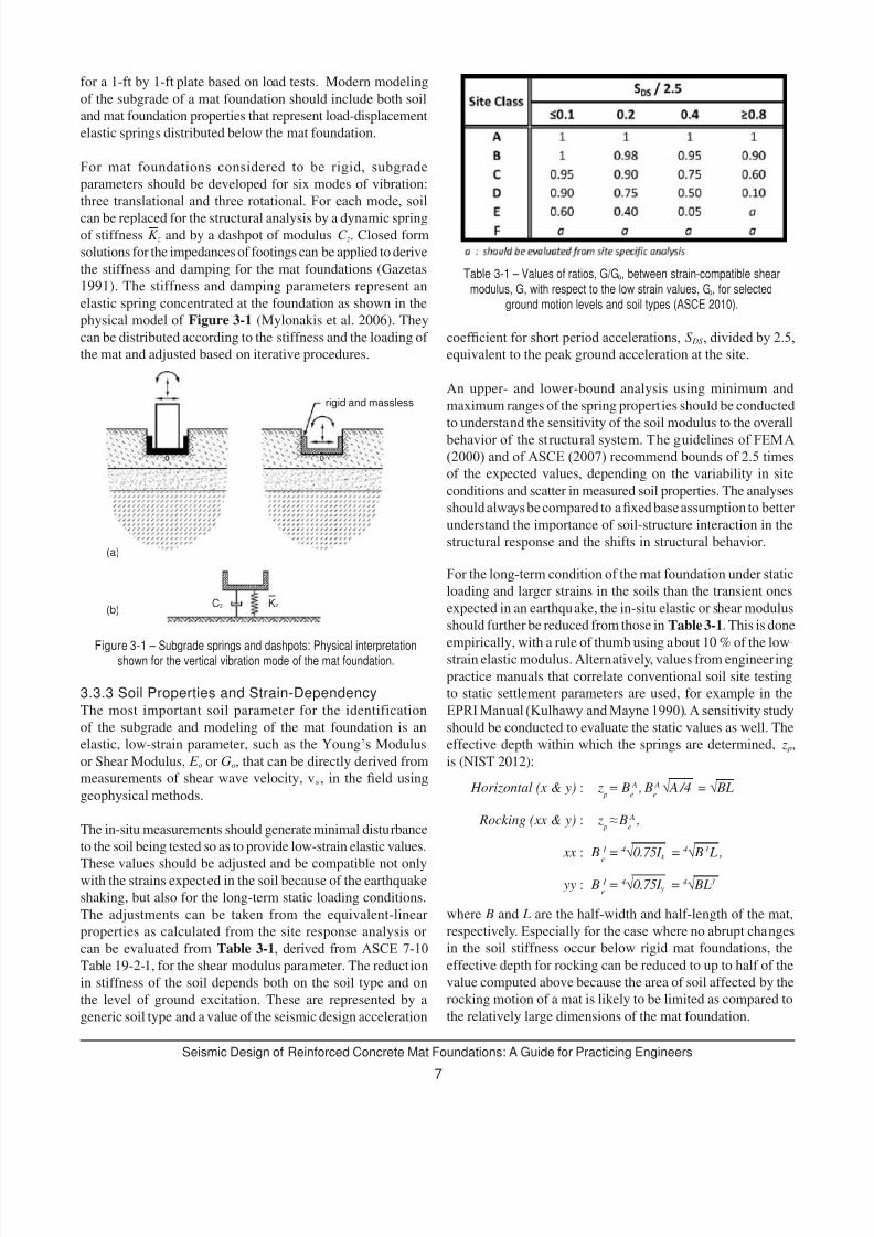
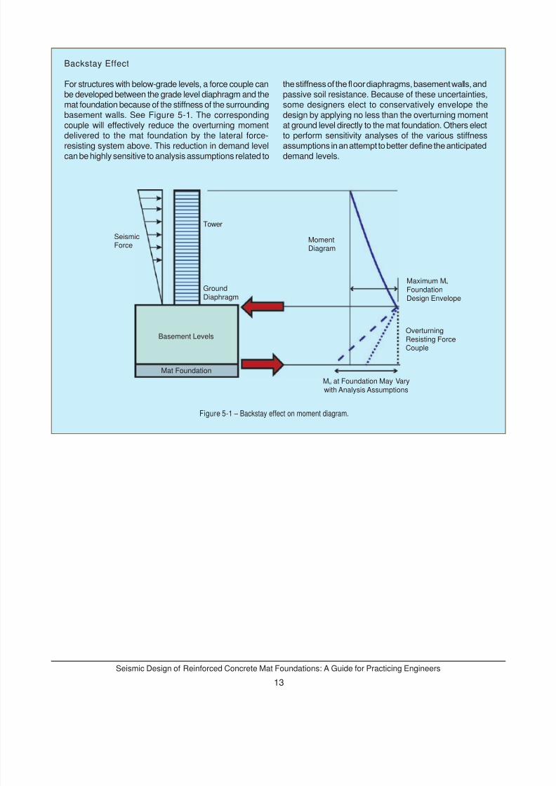
In the case of mat foundations placed within 10 feet of the
ground surface, seismic ground shaking can be considered
as the ground surface motion. In the case of mat foundations
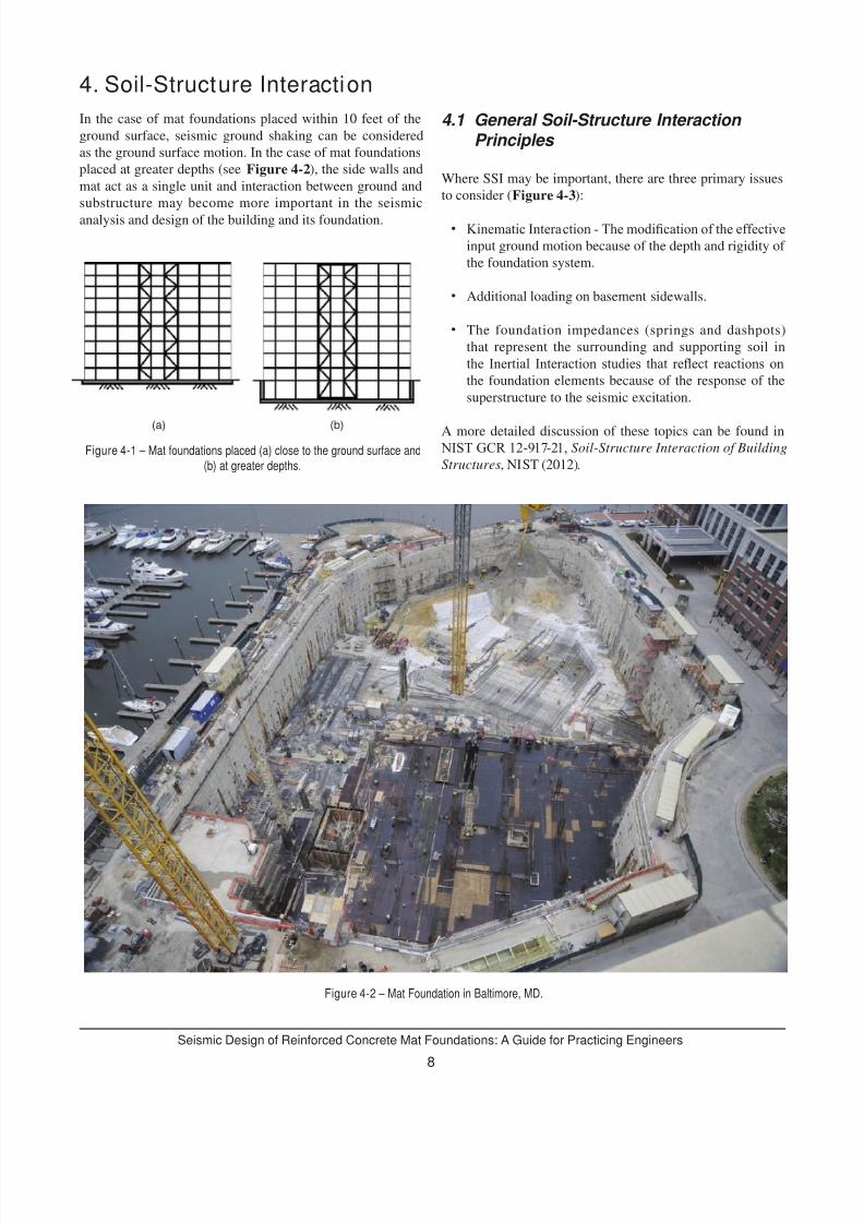
placed at greater depths (see Figure 4-2), the side walls and
mat act as a single unit and interaction between ground and
substructure may become more important in the seismic
analysis and design of the building and its foundation.
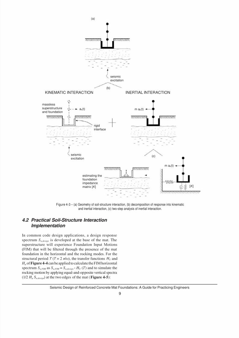
4.1 General Soil-Structure Interaction Principles
Where SSI may be important, there are three primary issues
to consider (Figure 4-3):
Kinematic Interaction - The modication of the effectiveinput ground motion because of the depth and rigidity of
the foundation system.
Additional loading on basement sidewalls.
The foundation impedances (springs and dashpots)
that represent the surrounding and supporting soil in
the Inertial Interaction studies that reect reactions onthe foundation elements because of the response of the
superstructure to the seismic excitation.
A more detailed discussion of these topics can be found in NIST GCR 12-917-21, Soil-Structure Interaction of Building
Structures, NIST (2012).
4. Soil-Structure Interaction
•
•
•
Figure 4-1 – Mat foundations placed (a) close to the ground surface and
(b) at greater depths.
Figure 4-2 – Mat Foundation in Baltimore, MD.
(b)(a)
7/30/2019 Seismic Design of Reinforced Concrete Mat Foundations by Ron Klemencic Et Al, NIST GCR 12-917-22, 08-2012.
http://slidepdf.com/reader/full/seismic-design-of-reinforced-concrete-mat-foundations-by-ron-klemencic-et-al 13/33
7/30/2019 Seismic Design of Reinforced Concrete Mat Foundations by Ron Klemencic Et Al, NIST GCR 12-917-22, 08-2012.
http://slidepdf.com/reader/full/seismic-design-of-reinforced-concrete-mat-foundations-by-ron-klemencic-et-al 14/33
7/30/2019 Seismic Design of Reinforced Concrete Mat Foundations by Ron Klemencic Et Al, NIST GCR 12-917-22, 08-2012.
http://slidepdf.com/reader/full/seismic-design-of-reinforced-concrete-mat-foundations-by-ron-klemencic-et-al 15/33
11
Seismic Design of Reinforced Concrete Mat Foundations: A Guide for Practicing Engineers
5. Load Combinations
Selecting the appropriate load combinations for the design
of mat foundations is critical. More than one set of load
combinations may be necessary to complete a mat foundation
design. The divide between a geotechnical engineer working
in allowable strength design (ASD) and structural engineer
working in ultimate strength design (USD) adds another layer
of complexity to load combinations. The typical procedure is
to proportion the foundation using allowable strength design
load combinations and then design the concrete foundation
element using ultimate strength design load combinations.
Proportioning in this case refers to sizing the soil-to-foundationinterface in terms of bearing pressure. Design refers to the
strength design of concrete, including the determination of
required exural or shear reinforcement.
5.1 ASD Load Combinations There are two types of allowable strength design load
combinations: basic allowable strength design and alternativebasic allowable strength design. Basic allowable strength
design load combinations (IBC 2012 §1605.3.1) are adoptedfrom ASCE 7, with the high overturning load combinationdened as 0.6 D + 0.7 E . The alternative basic allowable strength
design load combinations (IBC 2012 §1605.3.2) are legacy loadcombinations from the Uniform Building Code, with the high
overturning load combination dened as 0.9 D+ E /1.4.
A major difference between these load combinations for
the design of a mat foundation is the reduction of seismic
overturning effects at the soil-foundation interface as permitted
by ASCE 7-10 §12.13.4. This reduction of seismic overturning
(10 % or 25 % reduction depending on the analysis type)can be applied only if the basic allowable strength design
load combinations is used, not when the alternative basic
allowable strength design load combinations. The result is a
mat foundation design using basic allowable strength design
load combinations will typically be more conservative as
compared to a design using the alternative basic allowable
strength design load combinations. Although alternative basic
allowable strength design combinations are allowed in IBC, it
is expected they will eventually be removed from the code so
that all load combinations will be adopted from ASCE 7.
Noticeably absent from current building codes are a
safety factor for overturning and a required stability ratio.
Historically, a requirement to maintain a stability ratio (sumof the resisting moments divided by sum of the overturning
moments) equal or greater than 1.4 was adopted. However,current load combinations already include an inherent safety
factor by reducing the factor on dead load. In addition, current
building codes do not have an explicit requirement to eliminate
foundation rocking. Therefore, provided that a mat foundation
is able to maintain equilibrium under the applicable allowable
strength design load combination and not exceed the allowable
bearing pressure of the soil, the mat would be considered stable
and acceptable. If an adequate stability ratio is not achieved,
then tiedowns will be required.
5.2 USD Load Combinations
Load and resistance factor design load combinations are provided in IBC 2012 §1605.2 and are adopted from ASCE7. Similar to the basic allowable strength design loadcombinations, reducing the seismic overturning demands at
the soil-foundation interface using the load and resistance
factor design load combinations in accordance with ASCE7-10 §12.13.4 is permitted.
5.3 Additional Load Combination Considerations
Earthquake load effects, E, are dened in ASCE 7-10 §12.4.Inherent in the denition of these seismic demand levels is thestructural response modication factor, R, which is dependenton the type of lateral force-resisting system considered for the
superstructure. The same overturning that is determined at the
base of the superstructure is to be applied directly to the mat
foundation. Consideration of higher foundation demand levels
is triggered only by unusual structural geometries, such as a
cantilever column system or a discontinuous lateral system,
which require the consideration of a system overstrength factor,
per ASCE 7-10 §12.4.3. By dening earthquake load effectswith an inherent R value, some inelastic behavior is assumed in
the superstructure and therefore implies that a mat foundation
also may experience inelastic demands.
For any load combinations that include earthquake load effects,directionality in accordance with ASCE 7-10 §12.5 shall beconsidered. Additionally, the redundancy factor, ρ, per ASCE7-10 §12.3.4 shall be included.
Another component of load combinations for mat foundation
design is the vertical seismic load effect ( E v). Per ASCE 7-10§12.4.2.2, E v is permitted to be taken as zero when determining
demands on the soil-structure interface of foundations.
However, this is applied only to the basic allowable strengthdesign load combinations provided in ASCE 7. Similarly, per IBC 2012 §1605.3.2, E v is permitted to be taken as zero when
using the alternative basic allowable strength design load
combinations to proportion footings. Therefore, the vertical
seismic load effect does not need to be included in either
allowable strength design load combination for mat foundation
design.
7/30/2019 Seismic Design of Reinforced Concrete Mat Foundations by Ron Klemencic Et Al, NIST GCR 12-917-22, 08-2012.
http://slidepdf.com/reader/full/seismic-design-of-reinforced-concrete-mat-foundations-by-ron-klemencic-et-al 16/33
7/30/2019 Seismic Design of Reinforced Concrete Mat Foundations by Ron Klemencic Et Al, NIST GCR 12-917-22, 08-2012.
http://slidepdf.com/reader/full/seismic-design-of-reinforced-concrete-mat-foundations-by-ron-klemencic-et-al 17/33
7/30/2019 Seismic Design of Reinforced Concrete Mat Foundations by Ron Klemencic Et Al, NIST GCR 12-917-22, 08-2012.
http://slidepdf.com/reader/full/seismic-design-of-reinforced-concrete-mat-foundations-by-ron-klemencic-et-al 18/33
Seismic Design of Reinforced Concrete Mat Foundations: A Guide for Practicing Engineers
14
During preliminary design, mat foundations are commonly
proportioned considering overall building geometry,
performance objectives, and allowable bearing stresses. The
plan area of a mat foundation may be simply proportioned
using a rigid-body approximation as described in the HistoricalPerspectives section of this Technical Brief. Traditionally, matthickness has been determined considering punching shear
demands in accordance with ACI 318 §11.11.2.1 at core walls,columns, and any substantial concentrated loaded areas. Mat
foundations have not typically been proportioned considering
one-way shear or exure.
6.1 Proportioning for Bearing Pressure
For preliminary sizing, use of a rigid foundation assumption toestimate bearing pressures with a linear pressure distribution
can be appropriate. Although this is not the most technically
accurate approach when considering the actual foundation
and subgrade stiffness, it can be a helpful tool for initialproportioning until a complete analysis can be performed.
Refer to Section 2 for more discussion of this type of
analysis.
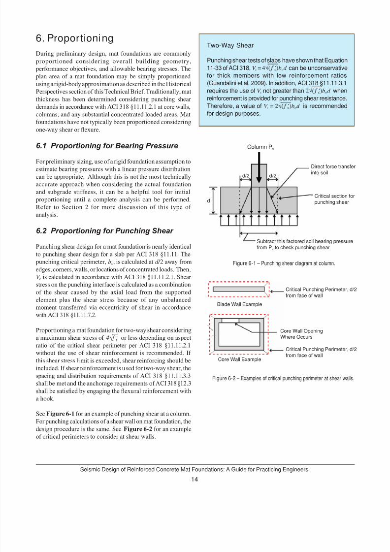
6.2 Proportioning for Punching Shear
Punching shear design for a mat foundation is nearly identicalto punching shear design for a slab per ACI 318 §11.11. Thepunching critical perimeter, bo, is calculated at d /2 away from
edges, corners, walls, or locations of concentrated loads. Then,
V c is calculated in accordance with ACI 318 §11.11.2.1. Shear stress on the punching interface is calculated as a combination
of the shear caused by the axial load from the supported
element plus the shear stress because of any unbalanced
moment transferred via eccentricity of shear in accordance
with ACI 318 §11.11.7.2.
Proportioning a mat foundation for two-way shear consideringa maximum shear stress of 4√ f ’ c or less depending on aspect
ratio of the critical shear perimeter per ACI 318 §11.11.2.1without the use of shear reinforcement is recommended. If
this shear stress limit is exceeded, shear reinforcing should be
included. If shear reinforcement is used for two-way shear, the
spacing and distribution requirements of ACI 318 §11.11.3.3shall be met and the anchorage requirements of ACI 318 §12.3shall be satised by engaging the exural reinforcement witha hook.
See Figure 6-1 for an example of punching shear at a column.
For punching calculations of a shear wall on mat foundation, thedesign procedure is the same. See Figure 6-2 for an example
of critical perimeters to consider at shear walls.
6. ProportioningTwo-Way Shear
Punching shear tests of slabs have shown that Equation
11-33 of ACI 318, V c = 4√( f ’ c)bod can be unconservative
for thick members with low reinforcement ratios
(Guandalini et al. 2009). In addition, ACI 318 §11.11.3.1
requires the use of V c not greater than 2√( f ’ c)bod when
reinforcement is provided for punching shear resistance.Therefore, a value of V c = 2√( f ’ c)bod is recommended
for design purposes.
Figure 6-1 – Punching shear diagram at column.
Figure 6-2 – Examples of critical punching perimeter at shear walls.
Column Pu
Direct force transferinto soil
Critical section forpunching shear
Subtract this factored soil bearing pressurefrom Pu to check punching shear
d
d/2 d/2
Blade Wall Example
Core Wall Example
Critical Punching Perimeter, d/2from face of wall
Core Wall OpeningWhere Occurs
Critical Punching Perimeter, d/2from face of wall
7/30/2019 Seismic Design of Reinforced Concrete Mat Foundations by Ron Klemencic Et Al, NIST GCR 12-917-22, 08-2012.
http://slidepdf.com/reader/full/seismic-design-of-reinforced-concrete-mat-foundations-by-ron-klemencic-et-al 19/33
15
Seismic Design of Reinforced Concrete Mat Foundations: A Guide for Practicing Engineers
6.3 Proportioning for Sliding
Sliding of the mat must also be considered. Sliding may
be resisted in whole or in part by friction between the mat
foundation and subgrade. In addition, if the mat foundation is
below grade with basement levels and a perimeter foundation
wall, passive resistance of the surrounding soil may also
be mobilized. The geotechnical engineer should advise the
structural engineer on the use of friction and passive resistance,
as it may not be appropriate to use these concurrently due to
the differences in displacement required to mobilize each
resistance mechanism. In addition, the construction means and
methods such as excavation and backll methods may affectthe sliding resistance values. The geotechnical engineer will
typically provide the structural engineer with the resistancevalues at a service level with a safety factor already included.
Therefore, the service level sliding shear demands can be
compared to the service level resistance values to ensure that
the demand does not exceed capacity.
One-Way Shear
Overall building geometry may result in a mat foundationextending over the entire footprint of the superstructure.However, in many buildings, seismic resistance isassigned to a limited number of shear walls and/orbraced frames, superstructure elements that impose
concentrated overturning moments on the foundation.In these cases, it may be appropriate to consider one-way shear in proportioning the mat thickness to maintainacceptable shear stress levels. There is disagreementin the ACI code committees on the best way to addressthis specic issue. Two variables, the effective width and
the maximum shear stress, are being debated. Currentbuilding code provisions allow for the consideration ofthe full width of the mat in evaluating one-way shearresistance. This does not seem reasonable or appropriatein the case of concentrated demands and the large widthof mat foundations. Peak shear stresses have traditionally
been considered as 2√ f ’ c, while some research (Reinecket al., 2003) suggests that for thick structural elements
in one-way shear this is unconservative, and 1√ f ’ c is amore appropriate shear stress threshold when no verticalreinforcement is provided. Larger crack widths in thickstructural elements can result in reduced aggregateinterlock and therefore reduced stress threshold. Recentpractice has adopted the use of an effective width equalto the width of the superstructure element imposingthe demand, plus one mat thickness either side of the
same element. This limited width, combined with a lower
shear stress threshold of 1√ f ’ c for mats with no verticalreinforcement is generally considered a conservativeapproach, perhaps overly so.
More recent research has investigated the size effecton shear and found that one-way shear capacity forlarge footings can be predicted with a slendernessparameter of the shear span divided by member depth,where the shear span is the distance from the face ofcolumn or wall to the point of zero shear (Uzel et al.,2011). It is challenging to relate shear capacity to theshear span for a complex mat foundation where theshear span may be unclear and there may be morethan 50 load combinations and, therefore, more than50 shear diagrams to consider to evaluate one-wayshear capacity.
When vertical reinforcement in accordance with ACI318 §11.4.6 is provided in a mat foundation, aggregateinterlock is maintained, and it is recommended to use
V c = 2√ f ’ c bd in combination with V s corresponding to thevertical reinforcement provided. Therefore, a thinnermat may be possible by providing a nominal amountof vertical reinforcement as compared to a mat withoutvertical reinforcement.
7/30/2019 Seismic Design of Reinforced Concrete Mat Foundations by Ron Klemencic Et Al, NIST GCR 12-917-22, 08-2012.
http://slidepdf.com/reader/full/seismic-design-of-reinforced-concrete-mat-foundations-by-ron-klemencic-et-al 20/33
Seismic Design of Reinforced Concrete Mat Foundations: A Guide for Practicing Engineers
16
Today, analysis of a mat foundation is typically performed
using nite element analysis software. The geometry, loading,and soil spring properties are dened as inputs, and the analysisresults typically include bearing pressure distributions,
mat deformations, and moment and shear diagrams. Some
analysis software can also be used to design and detail
exural reinforcement. This Technical Brief does not providerecommendations for any specific analysis software, but
instead provides analysis guidance that is common to most
mat foundation design.
The typical analysis for an isolated spread footing assumes
that the foundation is rigid with respect to the soil, where
a concentric load applied to the foundation would result in
uniform soil bearing. When a spread footing is compared to
a mat foundation, there is a fundamental difference in that
the stiffness of the mat foundation is included in the analysis.
The mat deforms as a result of bearing pressure, and bearing
pressure is redistributed according to the mat deformation.Therefore, a non-uniform bearing pressure distribution can
result. Methods used in the past often assumed a rigid mat
foundation with respect to the soil, but analysis including
foundation exibility can result in signicantly differentbearing pressure distributions and therefore different moment
and shear distributions.
7.1 Typical Modeling Practice
Finite element analysis of mat foundations typically assumesgross section concrete stiffness with no cracking. In developing
a numerical model for a mat foundation analysis model,
stiffness of the complete structure should be considered. For shear walls or basement walls above a mat foundation, the
in-plane exural stiffness should be added to the analysismodel. This can be accomplished with a very deep beam
or slab element. When beam or thickened slab elements are
used, it should be veried that the model is not overestimatingstiffness in an unanticipated manner, such as for torsion or
weak axis bending.
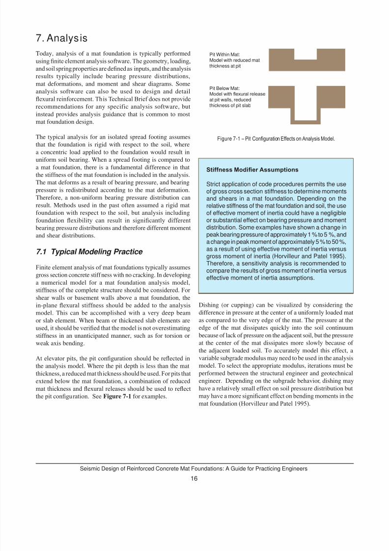
At elevator pits, the pit conguration should be reected inthe analysis model. Where the pit depth is less than the mat
thickness, a reduced mat thickness should be used. For pits thatextend below the mat foundation, a combination of reduced
mat thickness and exural releases should be used to reectthe pit conguration. See Figure 7-1 for examples.
Dishing (or cupping) can be visualized by considering the
difference in pressure at the center of a uniformly loaded mat
as compared to the very edge of the mat. The pressure at the
edge of the mat dissipates quickly into the soil continuum
because of lack of pressure on the adjacent soil, but the pressure
at the center of the mat dissipates more slowly because of
the adjacent loaded soil. To accurately model this effect, a
variable subgrade modulus may need to be used in the analysis
model. To select the appropriate modulus, iterations must be
performed between the structural engineer and geotechnical
engineer. Depending on the subgrade behavior, dishing may
have a relatively small effect on soil pressure distribution but
may have a more signicant effect on bending moments in themat foundation (Horvilleur and Patel 1995).
7. Analysis
Figure 7-1 – Pit Conguration Effects on Analysis Model.
Stiffness Modier Assumptions
Strict application of code procedures permits the use
of gross cross section stiffness to determine momentsand shears in a mat foundation. Depending on therelative stiffness of the mat foundation and soil, the useof effective moment of inertia could have a negligibleor substantial effect on bearing pressure and momentdistribution. Some examples have shown a change inpeak bearing pressure of approximately 1 % to 5 %, anda change in peak moment of approximately 5 % to 50 %,as a result of using effective moment of inertia versusgross moment of inertia (Horvilleur and Patel 1995).Therefore, a sensitivity analysis is recommended tocompare the results of gross moment of inertia versuseffective moment of inertia assumptions.
Pit Within Mat:Model with reduced matthickness at pit
Pit Below Mat:
Model with exural releaseat pit walls, reducedthickness of pit slab
7/30/2019 Seismic Design of Reinforced Concrete Mat Foundations by Ron Klemencic Et Al, NIST GCR 12-917-22, 08-2012.
http://slidepdf.com/reader/full/seismic-design-of-reinforced-concrete-mat-foundations-by-ron-klemencic-et-al 21/33
17
Seismic Design of Reinforced Concrete Mat Foundations: A Guide for Practicing Engineers
7.2 Analysis Options
Most analysis software commonly permit the use of a “thick
plate” element formulation to include the effects of shear
strains and therefore shear deformations. For very thick matfoundations, such as those with span-to-depth ratios of 10 or
less, this option should be used to provide a more realistic
force distribution.
No-tension iteration is a fundamental requirement of any niteelement software for mat foundation analysis. Upon application
of overturning or uplift forces on the mat, the software should
iterate to determine a soil bearing pressure distribution that
satises equilibrium but results in compression only in thesoil springs with zero tension. For mat foundations with largeoverturning or signicant uplift, the no-tension iteration maytake signicant computational effort. An analysis model thatis unable to complete the no-tension iteration could result in a
mat foundation that is under-proportioned, unstable, or both.
It is necessary to perform the no-tension iteration analysis for
each load combination. If the load cases were to be analyzed
separately, it would not be accurate to superimpose the bearing
pressure distribution, moments, shears, and deformations in
the mat due to the nonlinearity of the analysis.
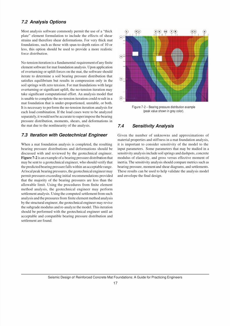
7.3 Iteration with Geotechnical Engineer
When a mat foundation analysis is completed, the resulting
bearing pressure distributions and deformations should be
discussed with and reviewed by the geotechnical engineer.
Figure 7-2 is an example of a bearing pressure distribution that
may be sent to a geotechnical engineer, who should verify that
the predicted bearing pressure falls within an acceptable range.
At local peak bearing pressures, the geotechnical engineer maypermit pressures exceeding initial recommendations provided
that the majority of the bearing pressures are less than the
allowable limit. Using the procedures from nite elementmethod analysis, the geotechnical engineer may perform
settlement analysis. Using the computed settlement from such
analysis and the pressures from nite element method analysisby the structural engineer, the geotechnical engineer may revise
the subgrade modulus and re-analyze the model. This iteration
should be performed with the geotechnical engineer until an
acceptable and compatible bearing pressure distribution and
settlement are found.
7.4 Sensitivity Analysis
Given the number of unknowns and approximations of
material properties and stiffness in a mat foundation analysis,
it is important to consider sensitivity of the model to the
input parameters. Some parameters that may be studied in a
sensitivity analysis include soil springs and dashpots, concrete
modulus of elasticity, and gross versus effective moment of
inertia. The sensitivity analysis should compare metrics such as
bearing pressure, moment and shear diagrams, and settlements.
These results can be used to help validate the analysis modeland envelope the nal design.
Figure 7-2 – Bearing pressure distribution example(peak value shown in grey color).
7/30/2019 Seismic Design of Reinforced Concrete Mat Foundations by Ron Klemencic Et Al, NIST GCR 12-917-22, 08-2012.
http://slidepdf.com/reader/full/seismic-design-of-reinforced-concrete-mat-foundations-by-ron-klemencic-et-al 22/33
Seismic Design of Reinforced Concrete Mat Foundations: A Guide for Practicing Engineers
18
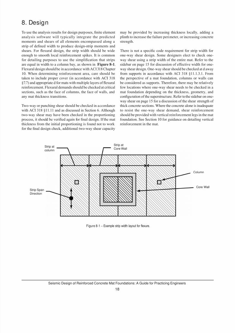
To use the analysis results for design purposes, nite elementanalysis software will typically integrate the predicted
moments and shears of all elements encompassed along a
strip of dened width to produce design-strip moments andshears. For exural design, the strip width should be wideenough to smooth local reinforcement spikes. It is common
for detailing purposes to use the simplication that stripsare equal in width to a column bay, as shown in Figure 8-1.
Flexural design should be in accordance with ACI 318 Chapter 10. When determining reinforcement area, care should be
taken to include proper cover (in accordance with ACI 318
§7.7) and appropriate d for mats with multiple layers of exuralreinforcement. Flexural demands should be checked at criticalsections, such as the face of columns, the face of walls, and
any mat thickness transitions.
Two-way or punching shear should be checked in accordance
with ACI 318 §11.11 and as discussed in Section 6. Although
two-way shear may have been checked in the proportioning process, it should be veried again for nal design. If the matthickness from the initial proportioning is found not to work
for the nal design check, additional two-way shear capacity
may be provided by increasing thickness locally, adding a
plinth to increase the failure perimeter, or increasing concrete
strength.
There is not a specic code requirement for strip width for one-way shear design. Some designers elect to check one-
way shear using a strip width of the entire mat. Refer to the
sidebar on page 15 for discussion of effective width for one-way shear design. One-way shear should be checked at d away
from supports in accordance with ACI 318 §11.1.3.1. Fromthe perspective of a mat foundation, columns or walls can
be considered as supports. Therefore, there may be relatively
few locations where one-way shear needs to be checked in a
mat foundation depending on the thickness, geometry, and
conguration of the superstructure. Refer to the sidebar on one-way shear on page 15 for a discussion of the shear strength of thick concrete sections. Where the concrete alone is inadequate
to resist the one-way shear demand, shear reinforcement
should be provided with vertical reinforcement legs in the matfoundation. See Section 10 for guidance on detailing vertical
reinforcement in the mat.
8. Design
Figure 8-1 – Example strip width layout for exure.
Strip SpanDirection
Strip atcolumn
Strip atCore Wall
Column
Core Wall
7/30/2019 Seismic Design of Reinforced Concrete Mat Foundations by Ron Klemencic Et Al, NIST GCR 12-917-22, 08-2012.
http://slidepdf.com/reader/full/seismic-design-of-reinforced-concrete-mat-foundations-by-ron-klemencic-et-al 23/33
19
Seismic Design of Reinforced Concrete Mat Foundations: A Guide for Practicing Engineers
9. Mats Supported on Deep Foundation Elements
Mat foundations supported on deep foundation elements
require additional consideration when compared to mat
foundations supported directly on soil.
For mat foundations supported on closely spaced deepfoundation elements, such as an extensive eld of precastpiles, the mat foundation may be analyzed and designed
similarly to a mat supported directly on soil. The geotechnical
engineer should be consulted to provide isolated springs for
each foundation element. Most nite element analysis toolsallow the denition of isolated springs with different tensionand compression stiffness values, which may be appropriate
depending on the deep foundation and soil properties. Upon
denition of these springs, the remainder of the design issimilar to a mat foundation supported directly on soil.
Alternatively, a mat foundation supported on few discrete
and widely spaced deep foundation elements may require a
much different approach to analysis and design. Where theangle between the foundation element axis and column or wall
axis is 25° or greater, strut and tie analysis should be used inaccordance with ACI 318 Appendix A. Alternatively, a niteelement analysis that accounts for nonlinear distribution of
strain could be used, however, strut and tie is more commonly
used in practice. It may be necessary to build a three-
dimensional strut and tie model to analyze a load path through
a mat foundation supported on large deep foundation elements.
A mat of this type is more analogous to a grade beam or pile
cap. When a strut and tie analysis is not employed, ACI 318
§15.5.4 provides additional requirements for the critical shear section of footings supported by piles. If piles are used, then
the critical location for the punching shear check may not beat a distance of d /2, as shown in Figure 6-1, but instead, at
the location of the piles.

7/30/2019 Seismic Design of Reinforced Concrete Mat Foundations by Ron Klemencic Et Al, NIST GCR 12-917-22, 08-2012.
http://slidepdf.com/reader/full/seismic-design-of-reinforced-concrete-mat-foundations-by-ron-klemencic-et-al 24/33
Seismic Design of Reinforced Concrete Mat Foundations: A Guide for Practicing Engineers
20
10. Detail ing
The detailing of a mat foundation should consider the ACI 318
requirements for reinforcement development, anchorage, and
curtailment. In addition, constructability issues should also
be kept in mind, as discussed in Section 11 of this Technical
Brief.
Flexural reinforcement should first be detailed to meetthe minimum shrinkage and temperature reinforcement
requirements of ACI 318 §7.12. Assuming Grade 60 deformedbar reinforcement, the ratio of reinforcement area to gross
concrete area of 0.0018 is to be provided in each direction.
This reinforcement requirement may be met by providing the
required area in the top or bottom layer or in a combination of
the two layers. Many designers will split this reinforcement
equally between the top and bottom reinforcement mats. In
addition to the minimum reinforcement mat, reinforcement
should be added as necessary to meet flexural strength
requirements. For a mat subject to uplift demands because
of earthquake effects, additional top reinforcement should be provided to meet the requirements of ACI 318 §21.12.2.4.When bar spacing in a single layer becomes too congested,
reinforcement should be placed in multiple layers. For thiscase, reinforcement layering and direction should be clearly
identied in the design drawings. See Figure 10-1.
Figure 10-1 – Example of placement diagram to clarify layering.
Where reinforcement is added for exural strength above the
minimum reinforcement requirement, the added reinforcementmay be curtailed in accordance with ACI 318 §12.10. Flexuralreinforcement may be cut off at a distance of d or 12d b beyond
the point it is no longer required. In a thick mat foundation,
this is almost always an extension distance d . It should also be
veried that the bar is fully developed at the critical section,such as at the face of the column or wall. When cutoff points
are determined, it is most efcient to round bar lengths toan interval that subdivides a stock length (20, 30, or 60 ft) to
minimize waste.
Lap splices are needed where bars are longer than stock length,typically 60 ft. Lap splice lengths should be in accordance withACI 318 §12.15. It is common to denote the typical lap splicelength on the design drawings and then allow the detailer to
lap where most efcient. Lap splices should be staggered 2 ftwhere possible.
In some markets, #14 and #18 bars are available in Grade 60
or Grade 75 and may be used to ease congestion of exuralreinforcement layers. The availability of these bars should be
conrmed, and the use should be discussed with the contractor.Both #14 and #18 bars require mechanical or welded splices
per ACI 318 §12.14.2.1, and #18 bars are quite heavy and mayrequire heavy equipment for placement.
Where provided, shear reinforcement should be detailed in
accordance with the anchorage requirements of ACI 318 §12.13,which requires that web reinforcement be extended as close to
the tension and compression surfaces as possible. In addition,ACI 318 §12.13.2 requires hooking shear reinforcementaround longitudinal reinforcement with additional embedment
requirements for #6 and larger bars. These detailing
requirements can be difcult to achieve for tightly spacedexural reinforcement mats when using larger diameter shear reinforcement bar with a 90° hook. Shear reinforcement isoften placed after both top and bottom mats are in place, and
therefore requires shing a hooked bar through the congestedreinforcement mats, as shown in Figure 10-2. Some designers
will use shear reinforcement with a head at the bottom that
may be easily dropped through the top and bottom reinforcing
mats. The disadvantage to headed bars is that they can be more
costly than hooked bars.
At moment frame columns and shear wall boundary elements,
dowels are required for the connection to the foundation. These
dowels must lap with the column or wall reinforcement and be
fully developed for tension into the mat. Refer to the sidebar for
discussion of aspects of this issue that are not fully speciedin the codes and standards.
Where a column or boundary element of a wall lands within
one-half of the footing depth from the edge of a mat, ACI
318 §21.12.2.3 requires that edge reinforcement be providedinto the depth of the footing. This requirement may be
satised by providing U-bars developed for fy in tension intothe foundation. See Figure 10-3. ACI 318 does not specify
how far to extend this reinforcement into the depth of the
mat foundation; however, it is recommended to extend the
reinforcement to the bottom of the mat foundation. This
requirement should also be applied where an elevator pit is
adjacent to a column or wall boundary element.

7/30/2019 Seismic Design of Reinforced Concrete Mat Foundations by Ron Klemencic Et Al, NIST GCR 12-917-22, 08-2012.
http://slidepdf.com/reader/full/seismic-design-of-reinforced-concrete-mat-foundations-by-ron-klemencic-et-al 25/33
21
Seismic Design of Reinforced Concrete Mat Foundations: A Guide for Practicing Engineers
Figure 10-2 – Mat foundation under construction, 90° hook shear reinforcement (painted orange) being placed from above.
Anchorage of Longitudinal Reinforcement
Longitudinal reinforcement of columns and structuralwalls must be developed into the mat foundation fortension in accordance with ACI 318-11 §21.12.2.1.There is no guidance in the building code regardingextension of longitudinal reinforcement any deeperthan the development length for either straight orhooked reinforcement. In the case of very thickfoundations, activation of the entire mat cross sectioncan be called into question. Some designers arguethat vertical reinforcement should be extended to thebottom of the mat foundation to create a completeload path to avoid the equivalent of a potential laminartearing problem as seen in steel plates. Additionally,from a constructability standpoint, it may be easier todetail bars that hook at the bottom of the mat so thatthey are not “oating” between the top and bottom
mats.
There is no code requirement to provide vertical reinforcementaround the edge of a mat foundation; however, it is good
practice to detail this reinforcement because of the possible
temperature gradient within the mat caused by the heat of
hydration and because of the exposed edge condition. Where
vertical shear reinforcement is being used throughout a mat,
the edge reinforcement can match the vertical reinforcement
size and spacing. Alternatively, a nominal bar of # 5 to # 9spaced at 12 to 24 inches on center may be used, depending
on the mat thickness.
Figure 10-3 – Example of edge reinforcement at mat foundation edge.
U-Bar Developed forfy in Tension
Column orBoundary Elementof Wall
Edge ofMat or Pit
7/30/2019 Seismic Design of Reinforced Concrete Mat Foundations by Ron Klemencic Et Al, NIST GCR 12-917-22, 08-2012.
http://slidepdf.com/reader/full/seismic-design-of-reinforced-concrete-mat-foundations-by-ron-klemencic-et-al 26/33
7/30/2019 Seismic Design of Reinforced Concrete Mat Foundations by Ron Klemencic Et Al, NIST GCR 12-917-22, 08-2012.
http://slidepdf.com/reader/full/seismic-design-of-reinforced-concrete-mat-foundations-by-ron-klemencic-et-al 27/33
23
Seismic Design of Reinforced Concrete Mat Foundations: A Guide for Practicing Engineers
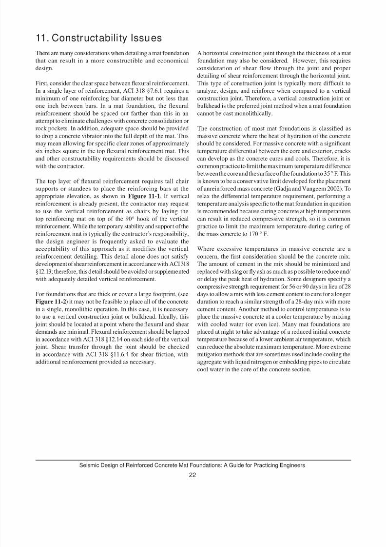
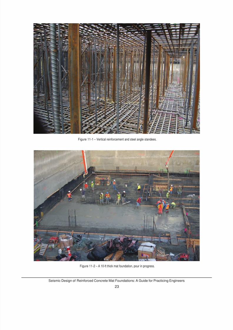
Figure 11-1 – Vertical reinforcement and steel angle standees.
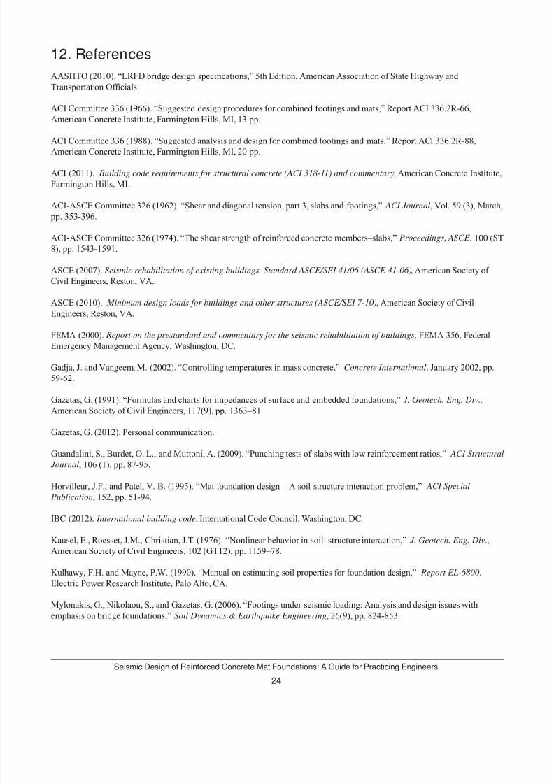
Figure 11-2 – A 10-ft thick mat foundation, pour in progress.
7/30/2019 Seismic Design of Reinforced Concrete Mat Foundations by Ron Klemencic Et Al, NIST GCR 12-917-22, 08-2012.
http://slidepdf.com/reader/full/seismic-design-of-reinforced-concrete-mat-foundations-by-ron-klemencic-et-al 28/33
Seismic Design of Reinforced Concrete Mat Foundations: A Guide for Practicing Engineers
24
AASHTO (2010). “LRFD bridge design specications,” 5th Edition, American Association of State Highway andTransportation Ofcials.
ACI Committee 336 (1966). “Suggested design procedures for combined footings and mats,” Report ACI 336.2R-66,
American Concrete Institute, Farmington Hills, MI, 13 pp.
ACI Committee 336 (1988). “Suggested analysis and design for combined footings and mats,” Report ACI 336.2R-88,
American Concrete Institute, Farmington Hills, MI, 20 pp.
ACI (2011). Building code requirements for structural concrete (ACI 318-11) and commentary, American Concrete Institute,
Farmington Hills, MI.
ACI-ASCE Committee 326 (1962). “Shear and diagonal tension, part 3, slabs and footings,” ACI Journal, Vol. 59 (3), March, pp. 353-396.
ACI-ASCE Committee 326 (1974). “The shear strength of reinforced concrete members–slabs,” Proceedings, ASCE , 100 (ST
8), pp. 1543-1591.
ASCE (2007). Seismic rehabilitation of existing buildings, Standard ASCE/SEI 41/06 (ASCE 41-06), American Society of Civil Engineers, Reston, VA.
ASCE (2010). Minimum design loads for buildings and other structures (ASCE/SEI 7-10), American Society of Civil
Engineers, Reston, VA.
FEMA (2000). Report on the prestandard and commentary for the seismic rehabilitation of buildings, FEMA 356, FederalEmergency Management Agency, Washington, DC.
Gadja, J. and Vangeem, M. (2002). “Controlling temperatures in mass concrete,” Concrete International, January 2002, pp.
59-62.
Gazetas, G. (1991). “Formulas and charts for impedances of surface and embedded foundations,” J. Geotech. Eng. Div.,
American Society of Civil Engineers, 117(9), pp. 1363–81.
Gazetas, G. (2012). Personal communication.
Guandalini, S., Burdet, O. L., and Muttoni, A. (2009). “Punching tests of slabs with low reinforcement ratios,” ACI Structural
Journal, 106 (1), pp. 87-95.
Horvilleur, J.F., and Patel, V. B. (1995). “Mat foundation design – A soil-structure interaction problem,” ACI Special
Publication, 152, pp. 51-94.
IBC (2012). International building code, International Code Council, Washington, DC.
Kausel, E., Roesset, J.M., Christian, J.T. (1976). “Nonlinear behavior in soil–structure interaction,” J. Geotech. Eng. Div.,
American Society of Civil Engineers, 102 (GT12), pp. 1159–78.
Kulhawy, F.H. and Mayne, P.W. (1990). “Manual on estimating soil properties for foundation design,” Report EL-6800,
Electric Power Research Institute, Palo Alto, CA.
Mylonakis, G., Nikolaou, S., and Gazetas, G. (2006). “Footings under seismic loading: Analysis and design issues withemphasis on bridge foundations,” Soil Dynamics & Earthquake Engineering, 26(9), pp. 824-853.
12. References
7/30/2019 Seismic Design of Reinforced Concrete Mat Foundations by Ron Klemencic Et Al, NIST GCR 12-917-22, 08-2012.
http://slidepdf.com/reader/full/seismic-design-of-reinforced-concrete-mat-foundations-by-ron-klemencic-et-al 29/33
7/30/2019 Seismic Design of Reinforced Concrete Mat Foundations by Ron Klemencic Et Al, NIST GCR 12-917-22, 08-2012.
http://slidepdf.com/reader/full/seismic-design-of-reinforced-concrete-mat-foundations-by-ron-klemencic-et-al 30/33
Seismic Design of Reinforced Concrete Mat Foundations: A Guide for Practicing Engineers
26
13. Notations and Abbreviations
ak kinematic acceleration
A area
b width of the footing
bo perimeter of critical section for shear
B half-width of the mat
C z dashpot coefcient
d distance from extreme compression ber to centroid of longitudinal tension reinforcement
d b nominal diameter of bar
D mat foundation embedment depth
e eccentricity of axial load relative to geometric centroid of section
E earthquake load effects
E o Young’s Modulus, low-strain elastic value
E v vertical earthquake load effects
f ’ c specied compressive strength of concrete
f E
fundamental frequency
f r Modulus of rupture of concrete
f y specied yield strength of reinforcement
G shear modulus, strain-compatible
Go shear Modulus, low-strain elastic value
H φ rocking transfer function
H U horizontal transfer function
I moment of inertia for the foundation
I g gross moment of inertia
K static stiffness
K z dynamic stiffness
l length of the footing
L half-length of the mat
m superstructure mass
7/30/2019 Seismic Design of Reinforced Concrete Mat Foundations by Ron Klemencic Et Al, NIST GCR 12-917-22, 08-2012.
http://slidepdf.com/reader/full/seismic-design-of-reinforced-concrete-mat-foundations-by-ron-klemencic-et-al 31/33
27
Seismic Design of Reinforced Concrete Mat Foundations: A Guide for Practicing Engineers
M moment
M cr cracking moment
M n nominal exural strength
M u factored moment
P axial force
Pu factored axial force
q bearing pressure
qa allowable soil bearing pressure
qu ultimate soil pressure
R response modication factor
S a,design design response spectrum
S a,FIM Foundation Input Motion (FIM) response spectrum
S DS seismic design acceleration coefcient for short period accelerations
t time
T structural period
V c nominal shear strength provided by concrete
V s nominal shear strength provided by shear reinforcement
vs soil or rock shear wave velocity
x longitudinal axis
y distance from centroid
y transverse axis
yt distance from centroidal axis of gross section
z vertical axis
Z p effective depth within which the springs are determined
ρ redundancy factor
φ strength reduction factor
w cyclic frequency
7/30/2019 Seismic Design of Reinforced Concrete Mat Foundations by Ron Klemencic Et Al, NIST GCR 12-917-22, 08-2012.
http://slidepdf.com/reader/full/seismic-design-of-reinforced-concrete-mat-foundations-by-ron-klemencic-et-al 32/33
Seismic Design of Reinforced Concrete Mat Foundations: A Guide for Practicing Engineers
28
Abbreviations
ACI American Concrete Institute
ASCE American Society of Civil Engineers
ATC Applied Technology Council
BSSC Building Seismic Safety Council
CUREE Consortium of Universities for Research in Earthquake Engineering
IBC International Building Code
NEHRP National Earthquakes Hazard Reduction Program
NIST National Institute of Standards and Technology
SEI Structural Engineering Institute
7/30/2019 Seismic Design of Reinforced Concrete Mat Foundations by Ron Klemencic Et Al, NIST GCR 12-917-22, 08-2012.
http://slidepdf.com/reader/full/seismic-design-of-reinforced-concrete-mat-foundations-by-ron-klemencic-et-al 33/33