Embed Size (px)
DESCRIPTION
Seismic Fragility Assessment of SCED Brace System us ing Hybrid Simulation. Oh-Sung Kwon Assistant Professor Viswanath Kammula MASc student Constantin Christopoulos Associate Professor Jeff Erochko PhD student. July 12, 2012. Outline. Seismic Fragility Function - PowerPoint PPT Presentation
Citation preview
Seismic Fragility Assessment of SCED Brace System using Hybrid Simulation
Oh-Sung Kwon Assistant ProfessorViswanath Kammula MASc student
Constantin Christopoulos Associate ProfessorJeff Erochko PhD student
July 12, 2012
Outline Seismic Fragility Function Reference Structure Hybrid Simulation Configuration Experimental Results Summary

Seismic Risk/Loss Assessment
Hazard
Scio-eco.impact
Inventorydata
Damageprediction
IM
P
Fragilityfunctions
0.0
0.2
0.4
0.6
0.8
1.0
0 0.05 0.10 0.15 0.20 0.25
Seismic Intensity (PGA, g)
Pro
babili
ty
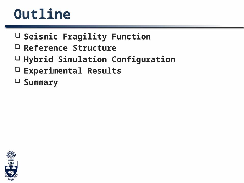
Seismic Fragility Functions Development of Seismic Fragility Functions
Empirical – post-earthquake survey Judgmental – experts’ opinion Analytical – numerical analysis of structures Hybrid (combination of above)
Most Common Methods in Industry Leading catastrophe modeling industries: EQECAT, AIR
Worldwide, RMS Methods: analysis, empirical, judgmental methods

Seismic Fragility Functions Analytical Derivation of Seismic Fragility Functions
Monte-Carlo simulation SAC-FEMA based approach Response surface method
ˆ bD aIM
ˆDD
ˆDD
log IM
logD
Identical dispersion
IM
logD
Median D at each IM are independent
2025
3035
4045
250
300
350
400
0.06
0.07
0.08
0.09
0.10
0.11
Concrete strength, fcSteel strength, fy
Fai
lure
pea
k ac
cele
ratio
n, g
2 20 1 2 3 4, , exp( )af c y c y c yS f F f F f F
Regardless of the method, analytical derivation highly
depends on the accuracy of analytical prediction.
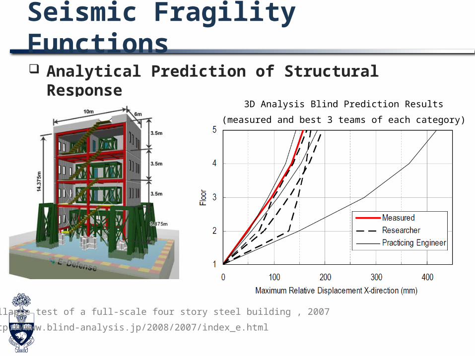
Seismic Fragility Functions Analytical Prediction of Structural Response
Collapse test of a full-scale four story steel building , 2007
http://www.blind-analysis.jp/2008/2007/index_e.html
3D Analysis Blind Prediction Results
(measured and best 3 teams of each category)
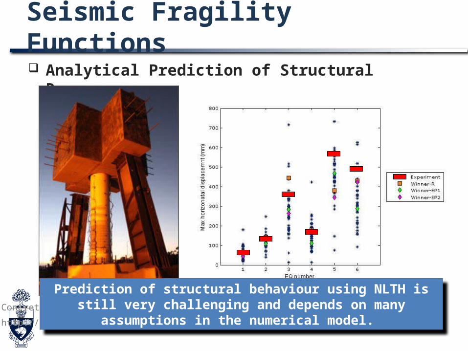
Seismic Fragility Functions Analytical Prediction of Structural Response
Concrete column blind prediction contest, 2010
http://nisee2.berkeley.edu/peer/prediction_contest/
Prediction of structural behaviour using NLTH is still very challenging and depends on many assumptions in the
numerical model.

Hybrid (Analysis-Experiment) Simulation
MUST-SIM Facility, UIUC
UI-SIMCOR
FEDEASLab
Vector 2
MatlabExperiment
Critical component can be physically tested in hybrid simulation
Hybrid simulation can reduce the gap between analytical prediction and actual behavior by representing critical
component(s) experimentally.

Objective To develop seismic fragility functions of a structure
with Self-Centering Energy-Dissipative (SCED) Braces using hybrid simulation

Outline Seismic Fragility Function Reference Structure Hybrid Simulation Configuration Experimental Results Current Research and Development in University of
Toronto

Self-Centering Systems Characterized with ‘flag-shape’ hysteresis loop Minimal residual deformation with energy
dissipation capacity Damage-free structural system
Self-centering moment resisting steel frame (Christopoulos et al. 2002, Herning et al. 2009)
Controlled rocking steel frame (Eatherton et al. 2010)
Segmental bridge bents (ElGawady and Sha’lan 2011)
Self-centering braces (Christopoulos et al. 2008)
among many others.
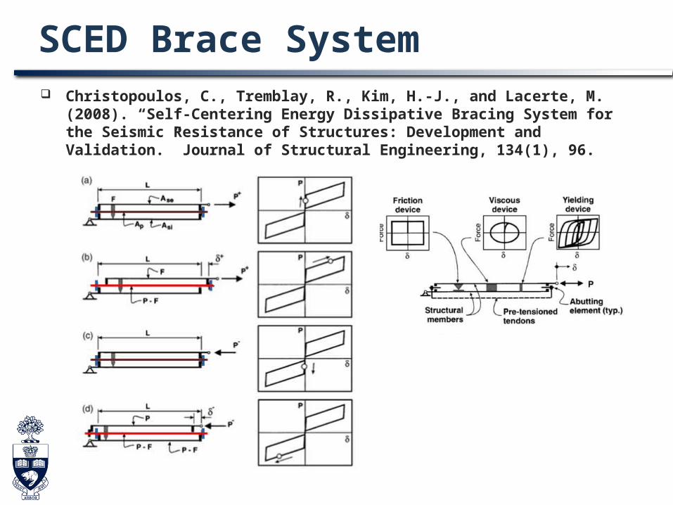
SCED Brace System Christopoulos, C., Tremblay, R., Kim, H.-J., and Lacerte, M. (2008). “Self-
Centering Energy Dissipative Bracing System for the Seismic Resistance of Structures: Development and Validation.” Journal of Structural Engineering, 134(1), 96.
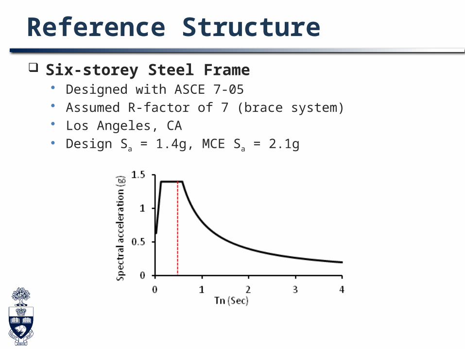
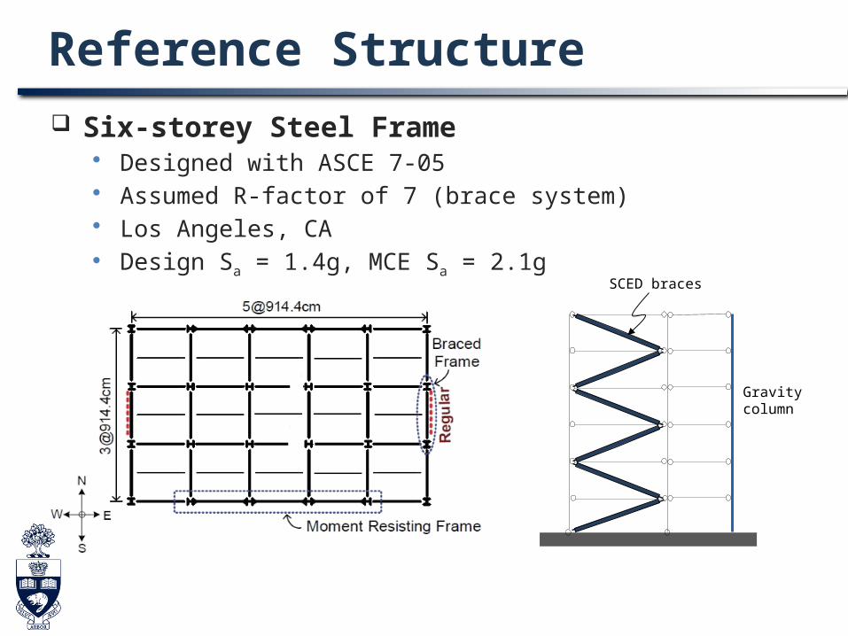
Reference Structure Six-storey Steel Frame
Designed with ASCE 7-05 Assumed R-factor of 7 (brace system) Los Angeles, CA Design Sa = 1.4g, MCE Sa = 2.1g
Reference Structure Six-storey Steel Frame
Designed with ASCE 7-05 Assumed R-factor of 7 (brace system) Los Angeles, CA Design Sa = 1.4g, MCE Sa = 2.1g
Gravity column
SCED braces

Input Ground Motions SAC-FEMA Method for fragility analysis Ground motions
Far-field motions from PEER-NGA Database Wide range of Sa at fundamental period of the structure Total thirty ground motions for hybrid simulation Scale factors of 0.65 ~ 1.1 are used to ensure that Sa are widely distributed Ground motions are truncated to reduce simulation time
ˆ bD aIM
ˆDD
ˆDD
log IM
logD
Identical dispersion

Outline Seismic Fragility Function Reference Structure Hybrid Simulation Configuration Experimental Results Current Research and Development in University of
Toronto

Hybrid Simulation Configuration
a) Whole Model c) Specimen d) OpenSeesb) UI-SimCor
Note: Gravity columns are included but not illustrated in the above figure.
SCED brace is a main lateral load resisting system.

NE
T W
OR
K
Hybrid Simulation ConfigurationU
I-S
imC
or
Command
MeasurementNICON
NI
ComactDAQUS
B MTS
FlexTest ControllerV
olta
ge MTS
Actuator
Act
ion
Specimen
PID Control Loop
Displacement feedback
NICA
PIP
E
OpenSeesCommand
Analysis Result
ACTIA
US
BCommand
Force feedback

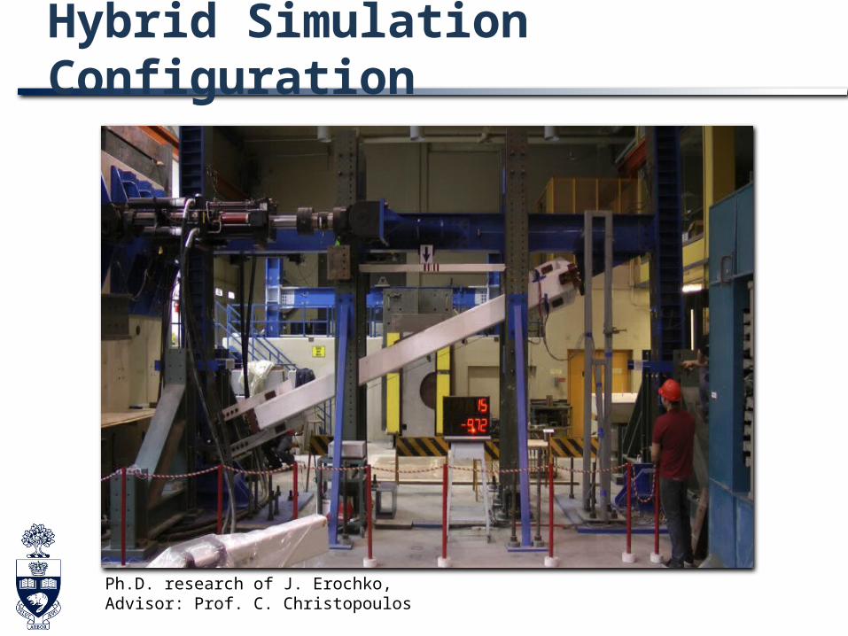
Hybrid Simulation Configuration
Ph.D. research of J. Erochko, Advisor: Prof. C. Christopoulos
Hybrid Simulation Configuration
Ph.D. research of J. Erochko, Advisor: Prof. C. Christopoulos

Static Cyclic Test
-600
-400
-200
0
200
400
600
-40 -30 -20 -10 0 10 20 30 40
Forc
e, k
N
Displacement, mm
Brace Hysteresis
Frame Hysteresis
Challenges Slackness in loading frame Implemented control algorithm based on external feedback
Outline Seismic Fragility Function Reference Structure Hybrid Simulation Configuration Experimental Results Current Research and Development in University of
Toronto

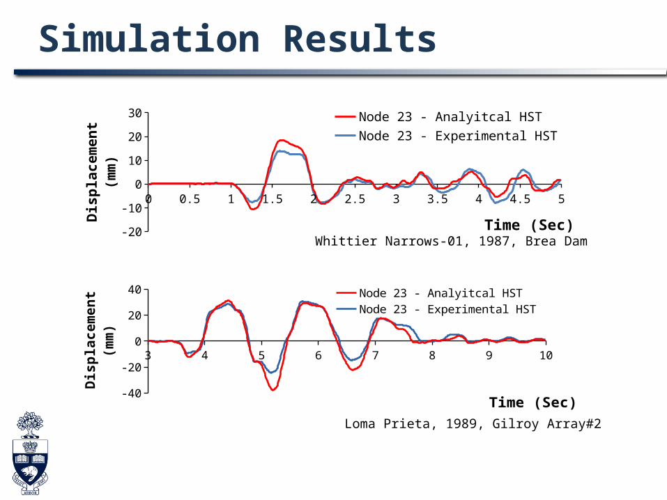
Simulation Results
0 0.5 1 1.5 2 2.5 3 3.5 4 4.5 5
-15-10-505
10152025 Node 23 - Analyitcal HST
Node 23 - Experimental HST
Time (Sec)
Dis
pla
cem
ent
(mm
)
Whittier Narrows-01, 1987, Brea Dam
3 4 5 6 7 8 9 10
-40-30-20-10
010203040 Node 23 - Analyitcal HST
Node 23 - Experimental HST
Time (Sec)
Dis
pla
cem
en
t (m
m)
Loma Prieta, 1989, Gilroy Array#2

Simulation Results
-40 -30 -20 -10 0 10 20 30 40 50 60
-400
-300
-200
-100
0
100
200
300
400
Analytical HST
Experimental HST
Displacement (mm)
Fo
rce
(K
N)
-5 -4 -3 -2 -1 0 1 2 3 4 5
-300
-200
-100
0
100
200
300
400
Analytical HST
Experimental HST
Displacement (mm)
Fo
rce
(K
N)
Difference in response was due to idealization of brace behavior with flag shape.

Simulation Results Seismic Demand
0.0 0.5 1.0 1.5 2.0 2.50.0
0.5
1.0
1.5
2.0 Analytical HST
Experimental HST
Spectral Acceleration (g)
Inte
rsto
rey
Dri
ft (
%)
Collapse prevention limit (ASCE 41-06)
Life safety limit (ASCE 41-06)
De
sig
n E
Q
Ma
xim
um
Cre
dib
le E
Q

Simulation Results Seismic Fragility Curves
0.0 0.5 1.0 1.5 2.0 2.5 3.00.0
0.2
0.4
0.6
0.8
1.0
Spectral Acceleration (g)
Pro
ba
bil
ity
of
fail
ure LS = 0.5%
LS = 1.0%
LS = 1.5%
LS = 2.0%
Analysis
Hybrid
Max
imum
Cre
dibl
e E
Q
Des
ign
EQ

Summary Seismic fragility functions of a structure with SCED
braces are developed using hybrid simulations. The structure, designed with ASCE 7-05, satisfied
inter-story drift limits in ASCE 41. This conclusion is preliminary, though, as the R
factor in ASCE 7 and performance limit in ASCE 41 are not calibrated for SCED braces.
Research is in progress to develop strategy for element selection and model updating.

Thank you!