Embed Size (px)
Citation preview

2nd Turkish Conference on Earthquake Engineering and Seismology – TDMSK -2013 September 25-27, 2013, Antakya, Hatay/Turkey
1
SEISMIC PERFORMANCE EVALUATION OF REINFORCED CONCRETE FRAMES
INFILLED WITH AUTOCLAVE AERATED CONCRETE MASONRY
U. A. Siddiqui1, H. Sucuoğlu2 and A. Yakut2
1 Research Assistant, Civil Eng. Department, Middle East Technical University, Ankara
2 Professor, Civil Eng. Department, Middle East Technical University, Ankara
Email: [email protected] ABSTRACT: This study investigates the seismic behaviour of four reinforced concrete frames, constructed in the Structural Dynamics Laboratory at Middle East Technical University and tested by the pseudo-dynamic testing procedure. These four specimens are examined in pairs of two: the “Non-conforming” with material and detailing deficiencies, and the “Code-conforming” compliant with Turkish Earthquake Code 2007. Each pair consists of one bare frame while another frame infilled with autoclave aerated concrete (AAC) block masonry. The focus of this study is to investigate the influence of AAC masonry infill panels on the seismic response of RC frames in both configurations. Numerical modelling of frames is conducted on the OpenSees platform following the guidelines of TEC-2007 and ASCE/SEI 41-06. The models, calibrated with experiments using time-history results, are used for assessment using pushover and time-history methods in accordance with the procedures of TEC-2007 and ASCE/SEI 41-06. The presence of AAC infills is found to considerably influence the deformation pattern, damage distribution and failure modes in the deficient frames whereas in the code-conforming frames the effect is not significant. Calibrating the models of deficient frames by using reduced nominal strengths and modified joint-offsets in order to predict accurate seismic response and damage distribution, is not efficient. To capture the deformation pattern on local scale, joint flexibility and frame-infill interaction needs to be explicitly accounted. The assessment of damage in members bounding the infill panels with the provisions of ASCE/SEI 41-06 gives accurate predictions of observed damages whereas provisions of TEC-2007 underestimates the damages for bounding members. KEYWORDS: Pseudo-dynamic Testing, Autoclave Aerated Concrete, Unreinforced Masonry Infill, Equivalent Strut, Performance Evaluation. 1. INTRODUCTION Several reinforced concrete buildings around the world are inadequately designed and/or constructed according to the regulations of present seismic codes and best practices. The recent devastating earthquakes in Turkey as well as other seismically active countries in the World, which caused significant economic and human loss, have grown concerns about the performance evaluation of these deficient buildings. Studies conducted by Sucuoğlu et al. (2007) have shown that commonly observed deficiencies are: plan irregularities, presence of heavy overhangs, low material strengths, inadequate member sizes, use of plain reinforcement, poor detailing in structural members and joint regions etc. In addition to these deficiencies, another important factor which affects the seismic performance evaluation, and is generally neglected, is the interaction of non-engineered masonry infill panels with the primary structural elements in resisting seismic loads. In the light of masonry infilled frame construction, the use of Autoclaved Aerated Concrete (AAC) masonry has gained familiarity due to its light weight and excellent fire resistant and thermal insulation capabilities which are ideal for seismic design and risk reduction. Because of these advantages, the utilization of AAC material for infill panels in areas of high seismicity have also gained popularity, for both new as well as rehabilitation of

2nd Turkish Conference on Earthquake Engineering and Seismology – TDMSK -2013 September 25-27, 2013, Antakya, Hatay/Turkey
2
existing construction hence, signifying the need of sufficient experimental and analytical research to study the seismic response of AAC masonry infilled RC construction. Thus the first task of this study is to provide experimental data on the seismic performance of reinforced concrete frames subjected to actual ground motions. Four ½ scale 3-story, 3-bay deficient concrete frames were tested using the pseudo-dynamic testing procedure under three consecutive ground motions with progressively increasing intensity levels. Performance assessment of existing concrete buildings has been a major concern since the last two decades in earthquake prone countries. ASCE/SEI 41-06, Eurocode 8-3 and the Turkish Earthquake Code (TEC) are the published codes and guidelines for regulating seismic performance evaluation of existing buildings in different parts of the World. In ASCE/SEI 41-06 and Eurocode 8-3, the performance limits are based on plastic end-rotation while TEC defines strain based performance limits. The newly outlined procedures in the TEC 2007 for the assessment and strengthening of existing buildings are the first to be employed in engineering practice around the globe. Leading earthquake engineering countries such as the USA and Japan do not have legal documents regarding this matter rendering comparative analyses impossible. Thus the second objective of this research is to validate the performance assessment procedures outlined in TEC and ASCE/SEI 41-06 in the light of experimental observations. In addition to experimental comparison, nonlinear analytical models are developed to perform validation of modelling parameters identified in the assessment codes. For this purpose, the experimental and analytical results are compared in terms of global and local responses to test the ability of models to predict the response. 2. TEST SPECIMENS The typical test frame comprises of the interior bay frame (Grid-3) of prototype three-story building (Figure 2.1). The dimension of columns was 400 x 300 mm with 1.33% reinforcement ratio while the beams were 300x350mm. Test frames were ½ scaled specimens of prototype shown in Figure-2.
a) Plan view of prototype building and test frame
b) Elevation of Specimen #1 and #3 [Bare Frames]
c) Elevation of Specimen #2 and #4 [Infilled Frames]
Figure 1. Plan view of prototype building and test frame (a) and elevations (dimensions in cm) (b&c) These four specimens were examined in pairs of two: the “Non-conforming” specimens (SP#1 and SP#2) with material and detailing deficiencies, and the “Code-conforming” (SP#3 and SP#4) compliant with Turkish Earthquake Code 2007. Each pair consists of one bare frame while another frame infilled with autoclave aerated concrete (AAC) block masonry in the middle bay. The average concrete compressive strength for Non-
2nd Turkish Conference on Earthquake Engineering and Seismology – TDMSK -2013 September 25-27, 2013, Antakya, Hatay/Turkey
3
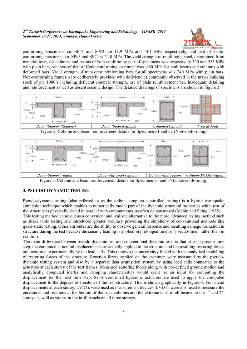
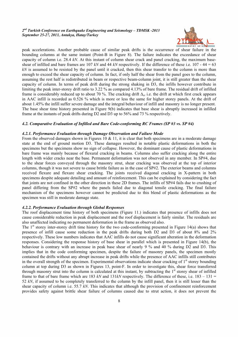
conforming specimens i.e. SP#1 and SP#2 are 11.9 MPa and 14.1 MPa respectively, and that of Code-conforming specimens i.e. SP#3 and SP#4 is 24.0 MPa. The yield strength of reinforcing steel, determined from material tests, for columns and beams of Non-conforming pair of specimens was respectively 320 and 355 MPa with plain bars, whereas of that of Code-conforming specimen was 480 MPa for both beams and columns with deformed bars. Yield strength of transverse reinforcing bars for all specimens was 240 MPa with plain bars. Non-conforming frames were deliberately provided with deficiencies commonly observed in the major building stock of pre 1980’s including deficient concrete strength, use of plain reinforcement bar, inadequate detailing and reinforcement as well as absent seismic design. The detailed drawings of specimens are shown in Figure 3.
Beam (Support Regions) Beam (Span Regions) Column (Typical) Typical Joint
Figure 2. Column and beam reinforcement details for Specimen #1 and #2 (Non-conforming)
Beam-Support region Beam-Mid span regions Column-End region Column-Middle region Figure 3. Column and beam reinforcement details for Specimen #3 and #4 (Code-conforming)
3. PSEUDO-DYNAMIC TESTING Pseudo-dynamic testing (also referred to as the online computer controlled testing) is a hybrid earthquake simulation technique which enables to numerically model part of the dynamic structural properties while rest of the structure is physically tested in parallel with computations, as often demonstrated (Mahin and Shing (1985). This testing method came out as a convenient and realistic alternative to the more advanced testing method such as shake table testing and introduced greater accuracy providing the simplicity of conventional methods like quasi-static testing. Other attributes are the ability to observe general response and resulting damage formation in structure during the test because the seismic loading is applied in prolonged time or “pseudo-time” rather than in real time. The main difference between pseudo-dynamic test and conventional dynamic tests is that at each pseudo time step, the computed structural displacements are actually applied to the structure and the resulting restoring forces are measured experimentally by the load cells. This removes the uncertainty linked with the analytical modelling of restoring forces of the structure. Reaction forces applied on the specimen were measured by the pseudo-dynamic testing system and also by a separate data acquisition system by using load cells connected to the actuators at each storey of the test frames. Measured restoring forces along with pre-defined ground motion and analytically computed inertia and damping characteristics would serve as an input for computing the displacement for the next time step. Servo-controlled hydraulic actuators are used to apply the computed displacement to the degrees of freedom of the test structure. This is shown graphically in Figure-4. For lateral displacements at each storey, LVDTs were used as measurement devices. LVDTs were also used to measure the curvatures and rotations at the bottom of the base columns and the extreme ends of all beams on the 1st and 2nd storeys as well as strains in the infill panels on all three storeys.

2nd Turkish Conference on Earthquake Engineering and Seismology – TDMSK -2013 September 25-27, 2013, Antakya, Hatay/Turkey
4
The typical elevations for bare and infilled frames and schematic view of testing are shown in Figure 6 for the test specimens having three translational degrees of freedom. Ground motions used for these pseudo-dynamic tests comprises of synthetic time-acceleration series of the 1999 Düzce earthquake. They were compatible with the site-specific earthquake design spectra for different exceedance probabilities on different soil types, as shown in Table 1.
a) Elevation view of bare frames b) Elevation view of infilled frames c) Pseudo-dynamic testing scheme
Figure 4. Test specimens (a & b) and Pseudo-dynamic testing scheme (c)
Table 1. Ground Motion Properties
Earthquake GM Probability of Exceedance in 50 Years Soil Class/Type PGA [g]
D1 50% Z1/Rock 0.254 D2 10% Z1/Rock 0.545 D3 10% Z3/Soft soil 0.604
Three of the generated acceleration series (named D1, D2, and D3) which were imposed on the test specimens sequentially are presented in Figure 5(a) along with the corresponding acceleration spectra in Figure 5(b).
a) Acceleration-Time Series (b) Acceleration Response spectra Figure 5. Acceleration time-series (a) and response spectra (b)
4. TEST RESULTS This section presents the experimental results of specimens for Non-conforming and Code-conforming specimens. The results includes response time histories measured during the three successive ground motions for global responses such as roof displacement, first storey drift ratio and base shear. In addition to the measured responses, the step by step gradual damage evolution of each specimen during the test is also presented correlated with certain peak roof displacements. Figures 6 shows the roof displacement time history of SP#1 and SP#2 with damage pictures presented in Figures 7 and 8 respectively for both specimens. Roof displacement time history for SP#3 and SP#4 is shown in Figure 9 and the damage pictures for both specimens are respectively presented in Figures 10 and 11. Time variation of 1st storey inter-storey drift ratio and base shear for SP#1 and SP#2 are presented in Figure 12 (a&b) whereas for SP#3 and SP#4 are shown in Figure 13(a&b).

2nd Turkish Conference on Earthquake Engineering and Seismology – TDMSK -2013 September 25-27, 2013, Antakya, Hatay/Turkey
5
Figure 6. Roof displacement time-history (SP#1 and SP#2)
A B C D E
E E E F
Figure 7. Observed damages correlated with roof displacement time history (SP#1)
Point A & B – Initiation of diagonal cracks in masonry panels at 1st and 2nd storey. Diagonal cracks at the top of Column-102 and cracks in flanges of exterior beams at support
Point C & D – Flexural cracks at the bottom of interior (left) and exterior (right) column
Point E – wide flexural cracks at the bottom of column-103 while shear cracking at the top of same column due to strut action.
Point E – Hinge Formation and permanent deformation of column-101. Overall damage to infill panels
Point F – Corner crushing of masonry infill blocks
Point G – Spalling of concrete and reinforcement buckling in column 103 at top
Figure 8. Observed damages correlated with roof displacement time history (SP#2)
~250mm

2nd Turkish Conference on Earthquake Engineering and Seismology – TDMSK -2013 September 25-27, 2013, Antakya, Hatay/Turkey
6
Figure 9. Roof displacement time-history (SP#3 and SP#4)
Point A & B –diagonal cracks in joints of 1st and 2nd storey and cracks in flanges of beams
Point C – Diagonal cracks in columns 101, 104, 201 and 204 and flexure cracks in beams 111 and 113
Point D – Joint diagonal cracking
Point E – Flexure cracks in exterior columns
Point F –Flexural cracks in int. columns
Point G – Widening of joint cracks. Distribution of flexural cracks in columns
Point H – Bond slip cracks in column 104
Figure 10. Observed damages correlated with roof displacement time history (SP#3)
Point A & B – diagonal cracks in infill panels and diagonal cracks 1st storey joints.
Point C & D –flexural cracks in exterior columns and beams of 1st storey
Point E and F – Diagonal cracking at top of 1st and 2nd storey interior columns
Point G – Distribution of diagonal cracks in 1st storey interior columns and Flexure shear cracks in exterior columns
Point H – Overall damage to the infill panels and diagonal cracks in 1st and 2nd storey joints.
Figure 11. Observed damages correlated with roof displacement time history (SP#4)
~300mm

2nd Turkish Conference on Earthquake Engineering and Seismology – TDMSK -2013 September 25-27, 2013, Antakya, Hatay/Turkey
7
(a)
(b)
Figure 12. 1st storey-drift ratio time-history (a) and 1st storey-shear time history (b) (SP#1 and SP#2)
(a)
(b)
Figure 13. 1st storey-drift ratio time-history (a) and 1st storey-shear time history (b) (SP#3 and SP#4)
4. EFFECT OF AAC INFILLS ON THE SEISMIC PERFORMANCE OF RC FRAMES 4.1. Comparative Evaluation of Infilled and Bare Non-conforming RC Frames (SP #1 vs. SP #2) 4.1.1. Performance Evaluation through Damage Observation and Failure Mode From the damage observations presented in Figure 7 and 8, it is apparent that both deficient specimens suffered severe damage at the end of ground motion D3. These damages resulted in large plastic deformations in members and residual displacements. However, the dominant cause of plastic deformations for both specimens differs greatly from each other. SP #1 failed primarily due to the flexure failure at the bottom ends of first storey column and top ends of second and third storey columns but the failure was abrupt with sudden increase in inter-storey drifts. Although some ductility was present but the ample warning usually associated with the flexural failure was absent in this specimen because the specimen was not designed for seismic loading. The failure of SP# 2 was also governed by the failure of first storey columns however the failure modes of columns differ from each other. The exterior columns depict flexure failure at the bottom but the failure was abrupt similar to the one observed in SP #1. On the other hand, the failure of interior columns surrounding the infill panel was brittle caused by excessive diagonal shear cracking at the top of columns. The main cause of such failure is the transfer of shear stress from the loaded diagonal of the infill panel and the absence of adequate confinement reinforcement to resist these stresses signifying the impact of poor seismic detailing. The cracking thereby resulted in spalling of concrete and buckling of reinforcement. The primary mode of failure of the first and second storey infill panels is severe diagonal cracking which is usual for a weak infill panel. 4.1.2. Performance Evaluation through Global Responses The roof displacement time history of both specimens (Figure 6.) indicates that presence of infills help in containing the peak displacement considerably up to about 45% during strong shaking in D3 as compared to bare frame. Significant reduction of up to 70% is also seen in the residual roof displacement of AAC infilled frame as expected. First storey inter-storey drift comparison presented in Figure 9(a) indicates that until the first cracking of infill at point A (during D2), the drift is contained very successfully, however, immediately after the cracking point during the reverse cyclic motion, when the crack in the column occurs at point-B, the drift is abruptly increased than that of bare frame up to 18%. The sudden cracking of brittle masonry panels can be the probable cause followed by a sudden drop in the stiffness of the infilled frame thereby causing large deformations at the
2nd Turkish Conference on Earthquake Engineering and Seismology – TDMSK -2013 September 25-27, 2013, Antakya, Hatay/Turkey
8
peak accelerations. Another probable cause of similar peak drifts is the occurrence of shear failure in the bounding columns at the same instant (Point-B in Figure 8). The failure indicates the exceedance of shear capacity of column i.e. 28.4 kN. At this instant of column shear crack and panel cracking, the maximum base-shear of infilled and bare frames are 107 kN and 44 kN respectively. If the difference of these i.e. 107 - 44 = 63 kN is assumed to be resisted by the panel until it cracked, then this shear transfer to the column is more than enough to exceed the shear capacity of column. In fact, if only half the shear from the panel goes to the column, assuming the rest half is redistributed in beam or respective beam-column joint, it is still greater than the shear capacity of column. In terms of peak drift during the strong shaking in D3, the infills however contribute in limiting the peak inter-storey drift ratio to 3.22 % as compared 4.13% of bare frame. The residual drift of infilled frame is considerably reduced up to about 70 %. The cracking drift Δcr i.e. the drift at which first crack appears in AAC infill is recorded as 0.526 % which is more or less the same for higher storey panels. At the drift of about 1.45% the infill suffer severe damage and the integral behaviour of infill and masonry is no longer present. The base shear time history presented in Figure 9(b) indicates that base shear is abruptly increased in infilled frame at the instants of peak drifts during D2 and D3 up to 56% and 73 % respectively. 4.2. Comparative Evaluation of Infilled and Bare Code-conforming RC Frames (SP #3 vs. SP #4) 4.2.1. Performance Evaluation through Damage Observation and Failure Mode From the observed damages shown in Figures 10 & 11, it is clear that both specimens are in a moderate damage state at the end of ground motion D3. These damages resulted in notable plastic deformations in both the specimens but the specimens show no sign of collapse. However, the dominant cause of plastic deformations in bare frame was mainly because of flexural cracking in beams. Columns also suffer cracking along the entire length with wider cracks near the base. Permanent deformation was not observed in any member. In SP#4, due to the shear forces conveyed through the masonry strut, shear cracking was observed at the top of interior columns, though it was not severe to cause brittle failure as in the case of SP#2. The exterior beams and columns received flexure and flexure shear cracking. The joints received diagonal cracking in X-pattern in both specimens despite adequate detailing and amount of reinforcement. This can be explained by considering the fact that joints are not confined in the other direction in these 2D frames. The infills of SP#4 fails due to crushing of panel differing from the SP#2 where the panels failed due to diagonal tensile cracking. The final failure mechanism of the specimens however cannot be predicted due to this blend of plastic deformations as the specimen was still in moderate damage state. 4.2.2. Performance Evaluation through Global Responses The roof displacement time history of both specimens (Figure 11.) indicates that presence of infills does not cause considerable reduction in peak displacement and the roof displacement is fairly similar. The residuals are also unaffected indicating no permanent deformation in the frame as observed also. The 1st storey inter-storey drift time history for the two code-conforming presented in Figure 14(a) shows that presence of infill cause some reduction in the peak drifts during both D2 and D3 of about 8% and 2% respectively. These low numbers indicates that AAC infills do not cause significant alteration in the deformation responses. Considering the response history of base shear in parallel which is presented in Figure 14(b), the behaviour is contrary with an increase in peak base shear of nearly 9 % and 40 % during D2 and D3. This implies that in the code conforming specimen, despite the failure of masonry panels, the specimen mostly contained the drifts without any abrupt increase in peak drifts while the presence of AAC infills still contributes in the overall strength of the specimen. Experimental observations indicate shear cracking of 1st storey bounding column at top during D3 as shown in Figures 13, point-F. In order to investigate this, shear force transferred through masonry strut into the column is calculated at this instant, by subtracting the 1st storey shear of infilled frame to that of bare frame which are 183 kN and 131kN respectively. The difference of these, i.e. 183 – 131 = 52 kN, if assumed to be completely transferred to the column by the infill panel, then it is still lesser than the shear capacity of column i.e. 55.7 kN. This indicates that although the provision of confinement reinforcement provides safety against brittle shear failure of columns caused due to strut action, it does not prevent the
2nd Turkish Conference on Earthquake Engineering and Seismology – TDMSK -2013 September 25-27, 2013, Antakya, Hatay/Turkey
9
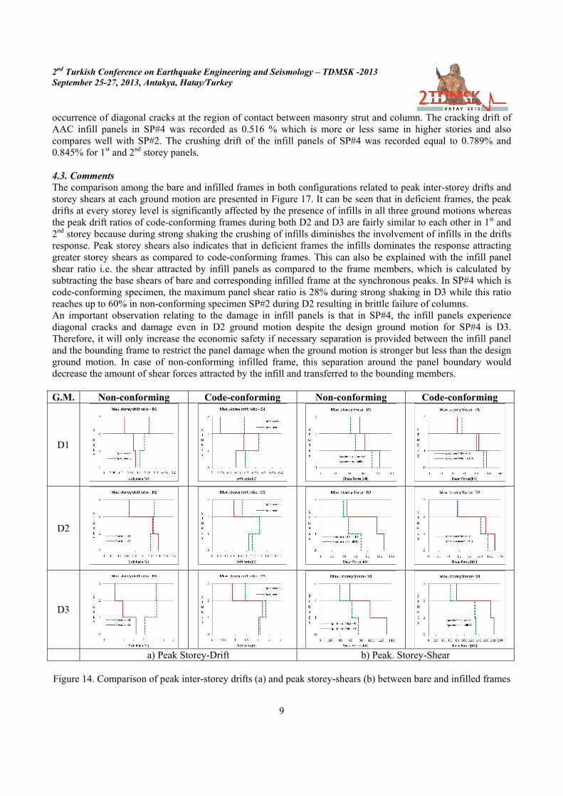
occurrence of diagonal cracks at the region of contact between masonry strut and column. The cracking drift of AAC infill panels in SP#4 was recorded as 0.516 % which is more or less same in higher stories and also compares well with SP#2. The crushing drift of the infill panels of SP#4 was recorded equal to 0.789% and 0.845% for 1st and 2nd storey panels. 4.3. Comments The comparison among the bare and infilled frames in both configurations related to peak inter-storey drifts and storey shears at each ground motion are presented in Figure 17. It can be seen that in deficient frames, the peak drifts at every storey level is significantly affected by the presence of infills in all three ground motions whereas the peak drift ratios of code-conforming frames during both D2 and D3 are fairly similar to each other in 1st and 2nd storey because during strong shaking the crushing of infills diminishes the involvement of infills in the drifts response. Peak storey shears also indicates that in deficient frames the infills dominates the response attracting greater storey shears as compared to code-conforming frames. This can also be explained with the infill panel shear ratio i.e. the shear attracted by infill panels as compared to the frame members, which is calculated by subtracting the base shears of bare and corresponding infilled frame at the synchronous peaks. In SP#4 which is code-conforming specimen, the maximum panel shear ratio is 28% during strong shaking in D3 while this ratio reaches up to 60% in non-conforming specimen SP#2 during D2 resulting in brittle failure of columns. An important observation relating to the damage in infill panels is that in SP#4, the infill panels experience diagonal cracks and damage even in D2 ground motion despite the design ground motion for SP#4 is D3. Therefore, it will only increase the economic safety if necessary separation is provided between the infill panel and the bounding frame to restrict the panel damage when the ground motion is stronger but less than the design ground motion. In case of non-conforming infilled frame, this separation around the panel boundary would decrease the amount of shear forces attracted by the infill and transferred to the bounding members. G.M. Non-conforming Code-conforming Non-conforming Code-conforming
D1
D2
D3
a) Peak Storey-Drift b) Peak. Storey-Shear
Figure 14. Comparison of peak inter-storey drifts (a) and peak storey-shears (b) between bare and infilled frames
2nd Turkish Conference on Earthquake Engineering and Seismology – TDMSK -2013 September 25-27, 2013, Antakya, Hatay/Turkey
10
5. PERFORMANCE EVALUATION OF TEST SPECIMENS USING CODE PROCEDURES The evaluation of performance assessment procedures mentioned in TEC 2007 and ASCE-41/06 in the light of experimental data is conducted using the strain based performance limits given in TEC 2007 and rotation based performance limits given in ASCE/SEI 41-06. First storey column member deformations measured from experiments along the plastic hinge length (1/2 of section depth) are used for this purpose assuming uniform strain distribution in this region. Performance of these column members is also assessed through careful visual inspection to enable the comparative evaluation between measured and observed response. Three performance limit states for ductile members defined in TEC 2007 and ASCE/SEI 41-06 are: Immediate Occupancy (IO), Life Safety (LS), and Collapse Prevention (CP). The corresponding damage levels between these performance limits specified in both TEC 2007 and ASCE/SEI 41-06 are Minimum Damage (MD), Significant Damage (SD), Heavy Damage (HD), and Collapse (C). The limit state strain values in accordance with TEC 2007, Chapter #7 for longitudinal steel in tension and concrete in compression for columns of both code-conforming and non-conforming specimens is shown in Table 2. These performance limits depend on the ratio of the provided confinement reinforcement ratio “ρs” vs. required confinement reinforcement ratio “ρsm” with an upper bound of “ρs/ρsm” equal to 1. For columns of non-conforming frames, the ratio “ρs/ρsm” is 0.33 whereas for columns of code-conforming frames it is 0.95. Columns in all specimens satisfy the requirements of ductile behaviour.
Table 2. TEC 2007 limiting strain values
Limiting strains
IO LS CP
Longitudinal Steel (Tension) 0.01 0.04 0.06
Confined Concrete (compression) 0.0035
The limiting values of plastic rotations for column members given in ASCE/SEI 41-06, Table 6-8 are presented here in Table 3. These values are interpolated bi-linearly based on two parameters which are axial load ratio P/Ag fc
’ and provided confinement reinforcement ratio “ρs”.
Table 3. ASCE/SEI 41-06 limiting values for plastic rotations
Specimen Column Plastic rotations
IO LS CP
Specimen #1 Bare Frame NC Exterior 0.0033 0.0063 0.0073 Interior 0.0029 0.0057 0.0065
Specimen #2 Infilled Frame NC Exterior 0.0034 0.0064 0.0076 Interior * * *
Specimen #3 Bare Frame CC Exterior 0.0049 0.024 0.032 Interior 0.0048 0.022 0.030
Specimen #4 Infilled Frame CC Exterior 0.0047 0.016 0.020 Interior * * *
* Refer to Table 5.3; [NC = non-conforming, CC = code-conforming] It should be noted that unlike TEC 2007, ASCE/SEI 41-06 provides separate performance limits in Table 6-16 which are based on total strains (compression/tension) for frame elements bounding the infill panels. The tensile strain limits for reinforcement steel are based on adequate/inadequate splicing whereas strain limits for concrete in compression depend on adequate/inadequate confinement. In our case, columns of SP #2 are inadequately confined whereas columns of SP #4 are properly confined. Table 4 presents the limiting strain values in accordance with ASCE/SEI 41-06 for bounding columns of the infilled frames. In case of infill panels, the performance limits are specified in both codes based on maximum inter-storey drifts and are given in Table 5.

2nd Turkish Conference on Earthquake Engineering and Seismology – TDMSK -2013 September 25-27, 2013, Antakya, Hatay/Turkey
11
It should be noted that in TEC 2007, these limits are defined only for strengthened infill panels but in ASCE/SEI 41-06, these limiting values are for unreinforced masonry infill panels. In addition to these limiting drift values for infill panels, ASCE/SEI 41-06 also defines the acceptance criteria based on observed damage which is as follows; for immediate-occupancy: significant visual cracking of an unreinforced infill panel occurs, for life-safety: substantial cracking of infill panel occurs and the potential is high for the panel, or some part of it, to drop out of the frame. In this study, this approach will be used to determine the performance based on the observations during experimental tests because the drift limits are not comparable due to difference in applicability.
Table 4. ASCE/SEI 41-06 limiting strain values for RC members bounding the infill panel
Specimen Strain Type Total Strain
IO LS CP
Specimen #2 NC Tension 0.01 0.03 0.04
Compression 0.002 0.002 0.003
Specimen #4 CC Tension 0.01 0.03 0.04
Compression 0.003 0.015 0.02
Table 5. Limiting drift values for infill panel
Specimen Limiting drifts (%)
IO LS CP
Specimen #2 NC TEC 2007 0.15 0.35 -
ASCE 41-06 - 0.3 -
Specimen #4 CC TEC 2007 0.15 0.35 -
ASCE 41-06 - 0.6 - The outcome of performance evaluation using measured local responses as well as objectively-assessed observed damages is presented in Table 6 and Table 7 for non-conforming specimen during D2 ground motion because D3 brings these deficient specimens to collapse. In case of code-conforming specimens, the outcome of evaluation is presented in Table 7 for D3 during which specimens received noticeable plastic deformation.
Table 6. 1st story column performance levels of SP1 and SP2 during D2
Performance assessment procedure
Specimen #1 (NC Bare Frame) Specimen #2 (NC Infilled Frame) Column
101 Column
102 Column
103 Column
104 Column
101 Column
102 Column
103 Column
104 Bot. Top Bot. Top Bot. Top Bot. Top Bot. Top Bot. Top Bot. Top Bot. Top
EXP (TEC) SD MD SD MD SD MD SD MD SD MD SD SD SD SD SD MD
EXP (ASCE) SD MD MD MD MD MD MD MD MD MD HD HD HD HD MD MD
Observation SD MD SD MD SD MD SD MD SD MD HD HD SD HD SD MD
Table 7. 1st story column performance levels of SP3 and SP4 during D3
Performance assessment procedure
Specimen #3 (CC Bare Frame) Specimen #4 (CC Infilled Frame) Column
101 Column
102 Column
103 Column
104 Column
101 Column
102 Column
103 Column
104 Bot. Top Bot. Top Bot. Top Bot. Top Bot. Top Bot. Top Bot. Top Bot. Top
EXP (TEC) HD MD HD MD SD MD SD MD HD SD HD SD SD SD SD SD
EXP (ASCE) SD MD SD MD SD MD SD MD SD MD HD HD HD HD MD MD
Observation SD MD SD MD SD MD SD MD SD MD HD HD SD HD SD MD

2nd Turkish Conference on Earthquake Engineering and Seismology – TDMSK -2013 September 25-27, 2013, Antakya, Hatay/Turkey
12
Observing the outcome of evaluation, it is evident that in general evaluation limits of TEC 2007 are more conservative than ASCE/SEI 41-06. The exception lies in the case of column members bounding the infill panels where the separate provision of ASCE/SEI 41-06 accurately predicts the damage with respect to the observed damage in both infilled frames (SP#2 and SP#4) while the generalized limits of TEC 2007 failed to predict the damage state in those bounding members. It can also be seen that in non-conforming specimens, the TEC strain based procedure assess the damage accurately while the ASCE limits under predicts the damage. In code-conforming frames, ASCE rotation based limits predicts the damage fairly accurately while TEC over predicts the damage. AAC infill panels of both infilled specimens performed significantly better than the expected performance based on limiting inter-storey drifts specified in both codes. 6. ANALYTICAL MODELLING The OpenSees Simulation Platform was used for generating the model of each specimen to simulate the seismic response of the test frame through performing non-linear time history analyses. Beams and columns in the OpenSees model were modelled using force-based elements defined by fibre sections at integration points. Second order geometric nonlinearity effects, i.e. P-delta effects were also considered in columns. Formulation of the Nonlinear Beam Column Element follows the Euler-Bernoulli beam theory, which ignores shear deformations. Rigid end zones in the columns and beams were provided as per the provisions of ASCE/ISE 41-06 depending upon their configuration of either the joint satisfies weak column-strong beam condition or vice versa based on the ratio of plastic moments of columns to the beams connecting into a joint. The concrete material model used in the model is Concrete01, which is the uniaxial Kent-Scott-Park (1971) concrete material model with no tensile strength and degraded linear unloading/reloading stiffness as proposed by Karsan-Jirsa (1969). Through this material model, confinement effects of transverse reinforcement were accounted for by increasing the strength and strain capacities of the unconfined concrete in order to reflect the behaviour of the concrete in the confined zones. Behaviour of steel reinforcement is modelled using a stress-strain relation was defined through the uniaxial Material ReinforcingSteel command with 90% of the yield and ultimate strength values of the reinforcing steel obtained from material tests, to provide more realistic predictions of column strengths. An onset strain hardening value of 0.01 and an ultimate strain value of 0.1 was used, as suggested by TEC 2007. Perfect bond between concrete and steel was assumed because in case of SP #1 and SP#2 the reinforcements comprises of continuous bars while in SP #3 and SP #4 the lap splices are code-conforming. Dynamic properties of the specimens were modelled as lumped masses at the nodes with Rayleigh damping assumed for the time history analyses. The Dynamic Ground-Motion analysis feature in OpenSees is used to perform non-linear dynamic response analysis of the frames. The resulting model contains 9 beam elements, 12 column elements, 16 nodes, and 48 degrees of freedom. In the case of infilled specimens, the models are provided with masonry struts using the TrussElement command in OpenSees. Two compression-only struts are connected concentrically at beam column joint in the middle bay at each storey level to represent the influence of AAC infill panels in both directions. The width of equivalent compression strut binf is estimated by using the provisions of ASCE-41/06 section 7.4. It is based on the characteristic parameter λ, first proposed by Stafford Smith. Similar formulation is also adopted in TEC 2007 Annex-7F for strengthened masonry panels. The mechanical properties of AAC masonry are obtained through compression tests on three AAC masonry prisms each 750mm in height, 150mm thick with a width of 250mm selected from the observed width of compression strut during pseudo-dynamic testing (see Figure 10 and 11). The maximum compressive strength, corresponding strain, initial and secant modulus of elasticity was determined as 2.66 MPa, 0.0022, 1430 MPa and 1209MPa respectively. The width of equivalent compression strut binf was thus calculated equal to 230mm. For the assignment of Force deformation (F-D) relationship of equivalent compression struts, comparative analysis was done among three different F-D relationships. First material model uses 1Dconcrete material representation from OpenSees for AAC material, second relationship uses one of the several F-D models presented in literature and the third F-D relationship, introduced in this study, utilizes the stress-strain curve of AAC masonry prism obtained from the compression test.

2nd Turkish Conference on Earthquake Engineering and Seismology – TDMSK -2013 September 25-27, 2013, Antakya, Hatay/Turkey
13
The outcome of comparative study showed that the F-D relationship proposed in this study, which utilizes the stress-strain curve directly to represent AAC masonry compression strut, performs better. The ability of numerical models to predict the response is evaluated in terms of error percentages by comparing 1st storey drift ratio and base shear time histories obtained from rigorous nonlinear analysis for each specimen. Time variation of 1st storey drift ratio and base shear are shown in Figures 15 to 18 (a&b) for SP #1, SP #2, SP#3 and SP #4 respectively.
a)
b)
Figure 15. 1st storey drift-ratio time history (a) and base shear time history (b) for Specimen #1
a)
b)
Figure 16. 1st storey drift-ratio time history (a) and base shear time history (b) for Specimen #2
a)
b)
Figure 17. 1st storey drift-ratio time history (a) and base shear time history (b) for Specimen #3
a)
b)
Figure 18. 1st storey drift-ratio time history (a) and base shear time history (b) for Specimen #4
In bare frames, for SP#1, the errors in peak 1st storey drift ratio during D1, D2 and D3 are 80%, 34% and 38% whereas for peak base shear the errors are 40%, 3.4% and 12% respectively. Similar errors for SP#3 for 1st storey drifts are 26%, 3% and 8% whereas for base shear are 14%, 2% and 4% respectively. In infilled frames, for SP#2, the errors in peak 1st storey drift ratio are 2.8%, 1.6%, 3.4% during D1, D2 and D3 whereas for peak

2nd Turkish Conference on Earthquake Engineering and Seismology – TDMSK -2013 September 25-27, 2013, Antakya, Hatay/Turkey
14
base shear the errors are 11%, 12% and 4%. Similar errors for SP #4 for 1st storey drift ratio are 1.4%, 13% and 0.5% whereas for base shear the errors are 8%, 3% and 8% respectively. The unacceptably high errors in the response-predictions from rigorous analytical models for non-conforming frames raise concerns about the applicability of code procedures for the assessment of seismic performance in deficient frames. In the case of deficient infilled frame specimens, the errors in drift ratios for upper stories are significantly higher than 1st storey. Also it should be noted that concentric strut model may be able to capture the global response of infilled frame, but in terms of local response, its applicability is also questionable as the errors in column end rotations are as high as 70% for SP #2. The models however work better in case of code-conforming specimens with overall errors mostly within ±15%. 7. CONCLUSIONS AND RECOMMENDATIONS Investigation of the influence of autoclave aerated concrete masonry infills on the global seismic response of four 3-storey, 3-bay RC frames, paired in deficient and code-conforming configurations and tested pseudo-dynamically, is presented in this thesis. Each pair consists of one bare frame while another frame infilled with AAC masonry panels in its middle bay. The comparison is made between the bare frame and the corresponding infilled frame using experimental test results in terms of primary failure mode, roof displacement, inter-storey drifts and storey shears. Experimental results are used for performance assessment in accordance with procedures of TEC-2007 and ASCE/SEI 41-06. The comparative analysis among the bare and infilled frames of each pair indicates that AAC infills detrimentally influence the response of non-conforming RC frames by stiffening the structure thereby attracting additional shear force which is on average twice as high as the column shear capacity, resulting in localized shear failure in bounding columns not designed for seismic loads. The infills cause overall increase in the capacity of the system and reduction in peak and residual displacements, however; after the failure of infills, the capacity of infilled frame reduces suddenly causing an abrupt increase in lateral deformation resulting in sudden flexure failure in non-bounding columns. In code conforming specimens, the AAC infill panels does not tend to dominate the response in a detrimental manner and during the strong shaking the bounding frame causes crushing of infill panel after which frame behaves similar to a bare frame. This leads to the conclusion that providing adequate confinement reinforcement may result in better performance of even the deficient RC frames infilled with AAC masonry. Therefore, the use of AAC masonry infills may prove advantageous in retrofitted deficient buildings as well as in code-compliant new construction which is designed by neglecting the influence of unreinforced masonry infills. Modelling and calibration of deficient systems using reduced nominal-strengths and modified joint-offsets in order to predict accurate seismic response and damage distribution is not very efficient. To capture the deformation pattern on local scale in order to be used for performance evaluation, joint flexibility and frame-infill interaction needs to be explicitly accounted-for using detailed joint-elements and eccentric strut models respectively. Performance evaluation of frames, in particular to the columns bounding the infill panels, separate strain-based provisions of ASCE accurately assess the observed damages in both infilled frames while the strain-based limits of TEC 2007, which are general for all RC members regardless of the presence of infills, failed to predict performance for bounding columns and under-predict their damage. Thus, addition of separate provisions in TEC 2007 for frame members bounding the unretrofitted masonry infills is necessary to accurately estimate the level of damage. With regards to the performance of masonry infill panels in both frames, the AAC masonry infill panels perform considerably better than the expected performance level in accordance with both codes, although TEC 2007 does not provide specific criteria for unretrofitted masonry infills. The observed performance and damage state of AAC masonry infills at code specified limiting drifts were significantly better than that predicted by codes.
2nd Turkish Conference on Earthquake Engineering and Seismology – TDMSK -2013 September 25-27, 2013, Antakya, Hatay/Turkey
15
REFERENCES Alexandre, A. C., Andrea, P., Guido, M., “Seismic performance of Autoclave Aerated Concrete (AAC) masonry: From experimental testing of the in-plane capacity of walls to building response simulation”, Journal of Earthquake Engineering: 2011, 15: pp. 1-31. American Society of Civil Engineers, “Seismic Rehabilitation of Existing Buildings”, ASCE/SEI 41:2006, Reston, Virginia. Comite European de Normalisation. "European Standard EN 1998-3:2005 Eurocode 8. Design of Structures for Earthquake Resistance - Part 3: Assessment and Retrofitting of Buildings", 2005. Karsan, I. D., and Jirsa, J. O., “Behaviour of Concrete under Compressive Loading”, Journal of the Structural Division (ASCE): 1969, Vol. 95, ST 12, pp. 2543-2563. Kent, D. C., and Park R., “Flexural Members with Confined Concrete”, Journal of the Structural Division (ASCE): 1971, Vol. 97, ST 7, pp. 1969-1990. Klingner, R.E., Bertero, V.V., “Earthquake resistance of infilled frames”, Journal of the Structural Division (ASCE):1978, Vol. 104, No. 6,pp. 973–989. Koutromanos, I., “Numerical analysis of masonry-infilled reinforced concrete frames subjected to seismic loads and experimental evaluation of retrofit techniques”, PhD Thesis: University of California, San Diego, 2011. Mahin, S. A., Shing, P. B., “Pseudo-dynamic Method for Seismic Testing”, Journal of Structural Engineering (ASCE):1985, Vol. 111, No. 7, pp. 1482-1503. Mazzoni et al., “OpenSees Command Language Manual”, Pacific Earthquake Engineering Research Center, 2007. Ministry of Public Works and Settlements, “Turkish code for buildings in seismic zones”, Turkish Earthquake Code: 2007, Ankara, Turkey, 159 pp. Ministry of Public Works and Settlement, “Requirements for Design and Construction of Reinforced Concrete Structures”, Turkish Standards Institution, TS 500: 2000, Ankara, Turkey. Mosalam, K.M.A., White, R.N., Ayala, G., “Response of infilled frames using pseudo-dynamic experimentation”, Earthquake Engineering and Structural Dynamics: 1998, Vol. 27, No. 6,pp. 589-608. Narayanan, N., Ramamurthy, K., “Structure and properties of aerated concrete – a review”, Cement and Concrete Composites: 2000, Vol. 22, pp. 321-329. Stafford Smith, B., “Methods of predicting the lateral stiffness and strength of Multi-storey Infilled frames”, Building Science: 1967, Vol. 2, pp 247-257. Sucuoğlu, H., Yazgan, U., Yakut, A., “A Screening Procedure for Seismic Risk Assessment in Urban Building Stocks,” Earthquake Spectra: 2007, Vol. 23, No. 2, pp. 441-458. Uva, G., Raffaele, D., Porco, F., Fiore, A., “On the role of equivalent strut models in the seismic assessment of infilled RC buildings”, Engineering Structures: 2012, 42, pp. 83-94.


![SEISMIC PERFORMANCE OF MASONRY-INFILLED · PDF fileSEISMIC PERFORMANCE OF MASONRY-INFILLED R.C. FRAMES: BENEFITS OF SLIGHT REINFORCEMENTS ... Zarnic and Tomazevic[38], Mosalam et al](https://img.pdfslide.net/doc/110x75/5aa8fab27f8b9a7c188c3cdf/seismic-performance-of-masonry-infilled-performance-of-masonry-infilled-rc.jpg)