Embed Size (px)
Citation preview
ABSTRACT: In this paper the transversal stability under seismic excitation of a possible structural solution for a pier container terminal is investigated. The considered solution adopts R.C. caisson structures resting on shallow foundations as vertical elements for the pier. The main aspect investigated is the caissons attitude to overturn due to excessive rocking at the base during earthquakes being the structure characterized by a shallow foundation. Being the caissons partially submerged bodies, the hydrodynamic effects associated to seismic excitation are included. The structure is verified by means of nonlinear time history analyses considering a set of spectrum compatible earthquake records. In the finite element model the caisson is schematized with mono-dimensional beam type elements. Soil-structure interaction is accounted for by placing compression-only axial springs with stiffness compatible to gravel soils. Both linear-elastic and elasto-plastic springs are considered. The resulting non-linear dynamic behaviour is characterized by limited uplift of the foundation relative to the soil, this uplift is responsible of the non-linearity, mainly geometric, related to soil-structure interaction. The analyses showed limited displacements of the caisson top, with higher values in the case of elasto-plastic soil with low elastic stiffness.
KEY WORDS: Rocking; Seismic performance; Soil structure interaction; Port structures.
1 INTRODUCTION
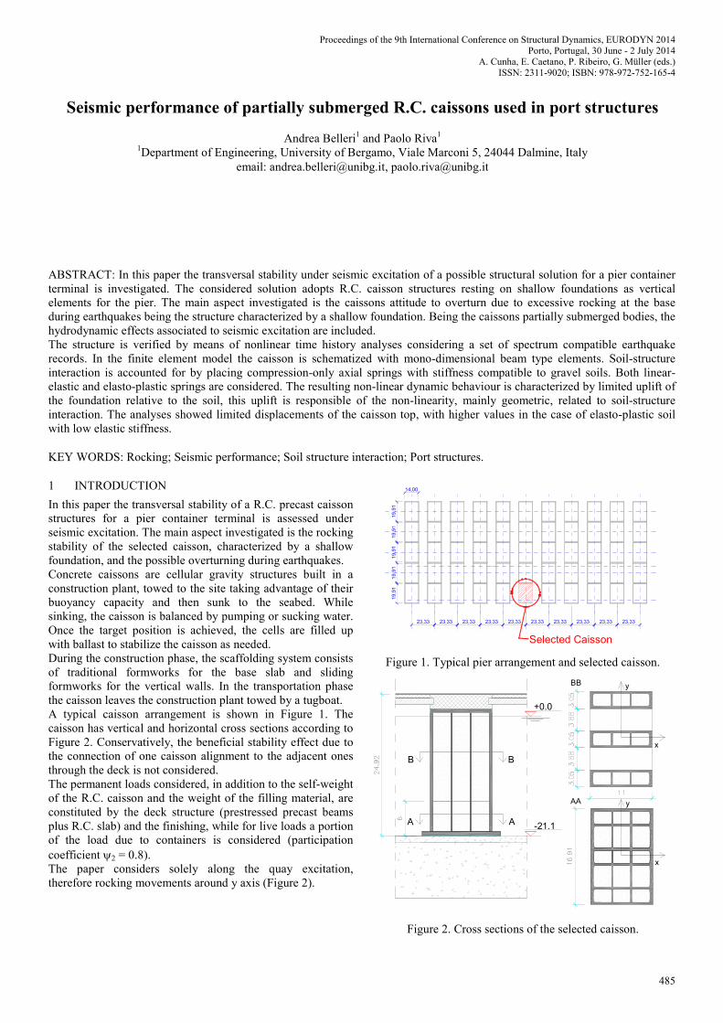
In this paper the transversal stability of a R.C. precast caisson structures for a pier container terminal is assessed under seismic excitation. The main aspect investigated is the rocking stability of the selected caisson, characterized by a shallow foundation, and the possible overturning during earthquakes. Concrete caissons are cellular gravity structures built in a construction plant, towed to the site taking advantage of their buoyancy capacity and then sunk to the seabed. While sinking, the caisson is balanced by pumping or sucking water. Once the target position is achieved, the cells are filled up with ballast to stabilize the caisson as needed. During the construction phase, the scaffolding system consists of traditional formworks for the base slab and sliding formworks for the vertical walls. In the transportation phase the caisson leaves the construction plant towed by a tugboat. A typical caisson arrangement is shown in Figure 1. The caisson has vertical and horizontal cross sections according to Figure 2. Conservatively, the beneficial stability effect due to the connection of one caisson alignment to the adjacent ones through the deck is not considered. The permanent loads considered, in addition to the self-weight of the R.C. caisson and the weight of the filling material, are constituted by the deck structure (prestressed precast beams plus R.C. slab) and the finishing, while for live loads a portion of the load due to containers is considered (participation coefficient 2 = 0.8). The paper considers solely along the quay excitation, therefore rocking movements around y axis (Figure 2).
19
,91
19
,91
19
,91
19
,91
19
,91
14,00
Selected Caisson
Figure 1. Typical pier arrangement and selected caisson.
+0.0
-21.1AA
BB
AA
BB
y
x
y
x
Figure 2. Cross sections of the selected caisson.
Seismic performance of partially submerged R.C. caissons used in port structures
Andrea Belleri1 and Paolo Riva1
1Department of Engineering, University of Bergamo, Viale Marconi 5, 24044 Dalmine, Italy email: [email protected], [email protected]
Proceedings of the 9th International Conference on Structural Dynamics, EURODYN 2014Porto, Portugal, 30 June - 2 July 2014
A. Cunha, E. Caetano, P. Ribeiro, G. Müller (eds.)ISSN: 2311-9020; ISBN: 978-972-752-165-4
485
2 SEISMIC ACTION
2.1 Structure classification and seismic zone
The structure is classified with an importance class II (EN 1998-1 par. 4.2.5) and the related importance factor I is equal to 1. Only the No-collapse Requirement (NCR) limit state is considered herein. The related probability of exceedance PNCR in the reference return period is 10% in 50 years, corresponding to a return period TNCR of 475 years. The site of interest is characterized by a maximum ground acceleration, for soil class “A”, of 0.20 g and the expected ground type is C.
2.2 Selected spectrum-compatible earthquake records
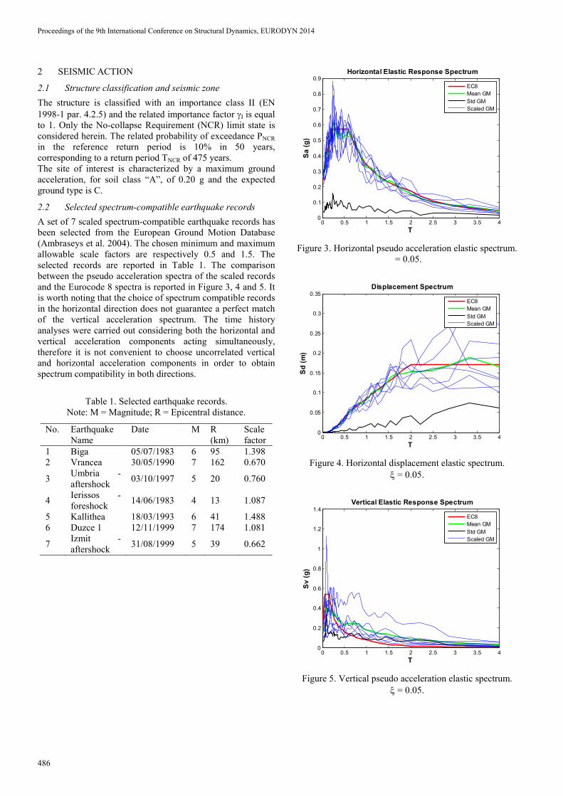
A set of 7 scaled spectrum-compatible earthquake records has been selected from the European Ground Motion Database (Ambraseys et al. 2004). The chosen minimum and maximum allowable scale factors are respectively 0.5 and 1.5. The selected records are reported in Table 1. The comparison between the pseudo acceleration spectra of the scaled records and the Eurocode 8 spectra is reported in Figure 3, 4 and 5. It is worth noting that the choice of spectrum compatible records in the horizontal direction does not guarantee a perfect match of the vertical acceleration spectrum. The time history analyses were carried out considering both the horizontal and vertical acceleration components acting simultaneously, therefore it is not convenient to choose uncorrelated vertical and horizontal acceleration components in order to obtain spectrum compatibility in both directions.
Table 1. Selected earthquake records. Note: M = Magnitude; R = Epicentral distance.
No. Earthquake Name
Date M R (km)
Scale factor
1 Biga 05/07/1983 6 95 1.398 2 Vrancea 30/05/1990 7 162 0.670
3 Umbria -aftershock
03/10/1997 5 20 0.760
4 Ierissos -foreshock
14/06/1983 4 13 1.087
5 Kallithea 18/03/1993 6 41 1.488 6 Duzce 1 12/11/1999 7 174 1.081
7 Izmit -aftershock
31/08/1999 5 39 0.662
0 0.5 1 1.5 2 2.5 3 3.5 40
0.1
0.2
0.3
0.4
0.5
0.6
0.7
0.8
0.9Horizontal Elastic Response Spectrum
T
Sa (
g)
EC8
Mean GM
Std GM
Scaled GM
Figure 3. Horizontal pseudo acceleration elastic spectrum. = 0.05.
0 0.5 1 1.5 2 2.5 3 3.5 40
0.05
0.1
0.15
0.2
0.25
0.3
0.35Displacement Spectrum
T
Sd
(m
)
EC8
Mean GM
Std GM
Scaled GM
Figure 4. Horizontal displacement elastic spectrum. = 0.05.
0 0.5 1 1.5 2 2.5 3 3.5 40
0.2
0.4
0.6
0.8
1
1.2
1.4Vertical Elastic Response Spectrum
T
Sv (
g)
EC8
Mean GM
Std GM
Scaled GM
Figure 5. Vertical pseudo acceleration elastic spectrum. = 0.05.
Proceedings of the 9th International Conference on Structural Dynamics, EURODYN 2014
486
3 HYDRODYNAMIC EFFECTS
Being the caissons partially submerged bodies, they will be subjected to hydrodynamic effects (Newman 1977). The present report considers the hydrostatic pressure and the hydrodynamics effects associated to seismic excitation. The influence of wave loads, currents and tides are not considered. In the case of ground movement, earthquake type loading, it is possible to assume that the viscous effect and the velocity gradient of the fluid are limited to the base of the structure, therefore in this report the water is considered at rest above the layer in contact to the ground: displacement, velocity and acceleration of the caissons with respect to the surrounding water are obtained as the sum of the ground component and the caisson to ground relative values. The hydrodynamic effects considered herein are the hydrostatic buoyancy and the hydrodynamic added mass. The hydrostatic buoyancy needs to be considered because it will limit shear friction capacity at the foundation level. This load is not converted into seismic mass. The hydrodynamic added mass is related to inertial effects due to pressure gradient generation by the acceleration of the fluid as a consequence of structural movements. This effect is considered adding a hydrodynamic mass related to the cross-section shape and to the distance from the free surface (Figure 6). For structures with rectangular cross-section, the added
mass 0m could be evaluated (EN 1998-2:2005 Annex F) as:
0 2
M ym C a (1)
where:
is the fluid density
ay is the semi-dimension of the cross-section in the direction perpendicular to the flow
CM is a factor depending on the ratio ay/ax
Figure 6. Geometry for added mass calculation
For the considered caisson, the relevant values are
0 2321m m and 0 213.9m m for cross-section
type AA and BB. A correction factor f(z) is necessary in order to consider the reduction of hydrodynamic added mass related to the position of the considered cross-section compared to the water free surface (Goyal and Chopra 1989).The added mass distribution of the selected caissons as a function of elevation is reported in Table 2. The hydrodynamic inertial contribution to vertical translation is negligible.
Table 2. Selected earthquake records.
z z/H0 0am /
0m Section 0am
(m)
(kg)
21 1 0 AA 0
20 0.95 0.37 AA 27703
18 0.86 0.64 AA 54977
16 0.76 0.77 AA 66359
14 0.67 0.84 AA 72158
12 0.57 0.88 AA 75594
10 0.48 0.91 AA 78170
8 0.38 0.93 AA 79888
6 0.29 0.77 BB 403717
4 0.19 0.78 BB 517435
2 0.10 0.79 BB 524049
0 0 0.8 BB 264504
4 FINITE ELEMENT MODEL
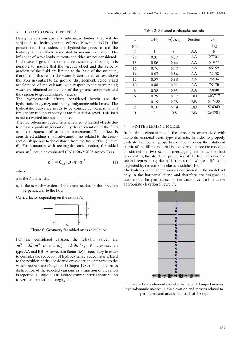
In the finite element model, the caisson is schematized with mono-dimensional beam type elements. In order to properly evaluate the inertial properties of the caissons the rotational inertia of the filling material is considered, hence the model is constituted by two sets of overlapping elements, the first representing the structural properties of the R.C. caisson, the second representing the ballast material, whose stiffness is neglected by reducing the elastic modulus (E). The hydrodynamic added masses considered in the model act only in the horizontal plane and therefore are assigned as translational lumped masses on the caisson centre-line at the appropriate elevation (Figure 7).
Figure 7 – Finite element model scheme with lumped masses: hydrodynamic masses in the elevation and masses related to
permanent and accidental loads at the top.
Proceedings of the 9th International Conference on Structural Dynamics, EURODYN 2014
487
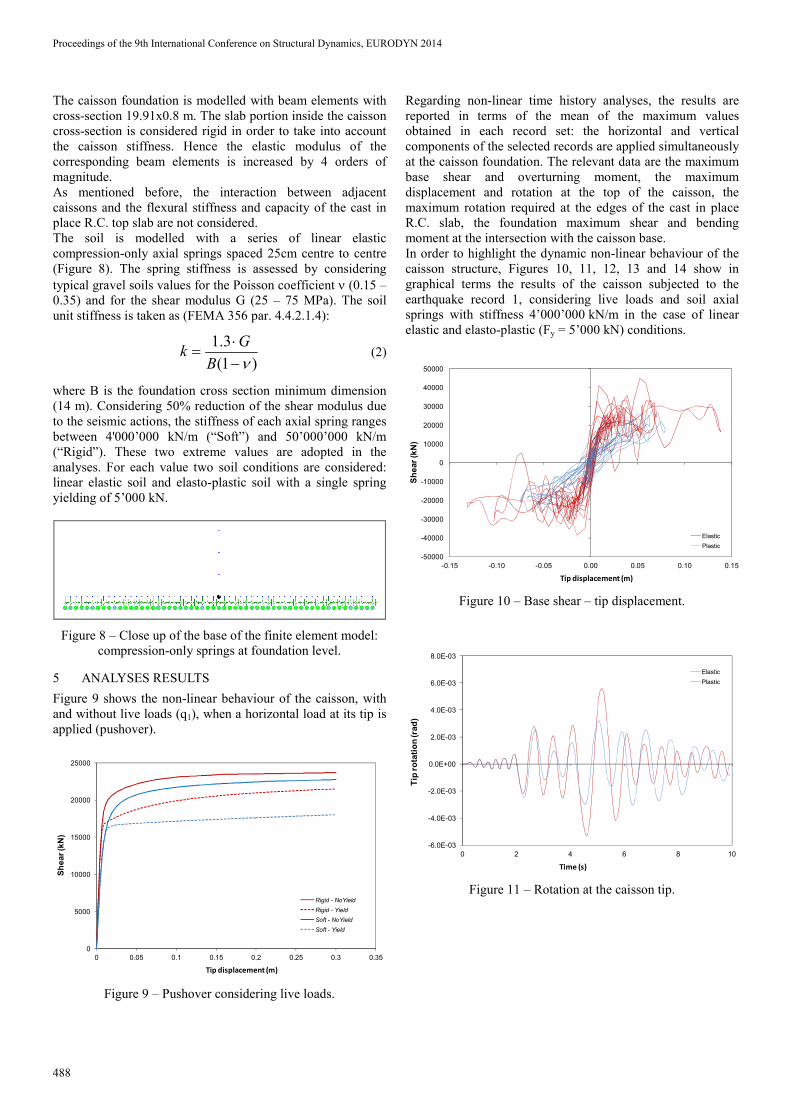
The caisson foundation is modelled with beam elements with cross-section 19.91x0.8 m. The slab portion inside the caisson cross-section is considered rigid in order to take into account the caisson stiffness. Hence the elastic modulus of the corresponding beam elements is increased by 4 orders of magnitude. As mentioned before, the interaction between adjacent caissons and the flexural stiffness and capacity of the cast in place R.C. top slab are not considered. The soil is modelled with a series of linear elastic compression-only axial springs spaced 25cm centre to centre (Figure 8). The spring stiffness is assessed by considering typical gravel soils values for the Poisson coefficient (0.15 – 0.35) and for the shear modulus G (25 – 75 MPa). The soil unit stiffness is taken as (FEMA 356 par. 4.4.2.1.4):
1.3
(1 )
Gk
B
(2)
where B is the foundation cross section minimum dimension (14 m). Considering 50% reduction of the shear modulus due to the seismic actions, the stiffness of each axial spring ranges between 4'000’000 kN/m (“Soft”) and 50’000’000 kN/m (“Rigid”). These two extreme values are adopted in the analyses. For each value two soil conditions are considered: linear elastic soil and elasto-plastic soil with a single spring yielding of 5’000 kN.
Figure 8 – Close up of the base of the finite element model: compression-only springs at foundation level.
5 ANALYSES RESULTS
Figure 9 shows the non-linear behaviour of the caisson, with and without live loads (q1), when a horizontal load at its tip is applied (pushover).
0
5000
10000
15000
20000
25000
0 0.05 0.1 0.15 0.2 0.25 0.3 0.35
Sh
ea
r (k
N)
Tip displacement (m)
Rigid - NoYield
Rigid - Yield
Soft - NoYield
Soft - Yield
Figure 9 – Pushover considering live loads.
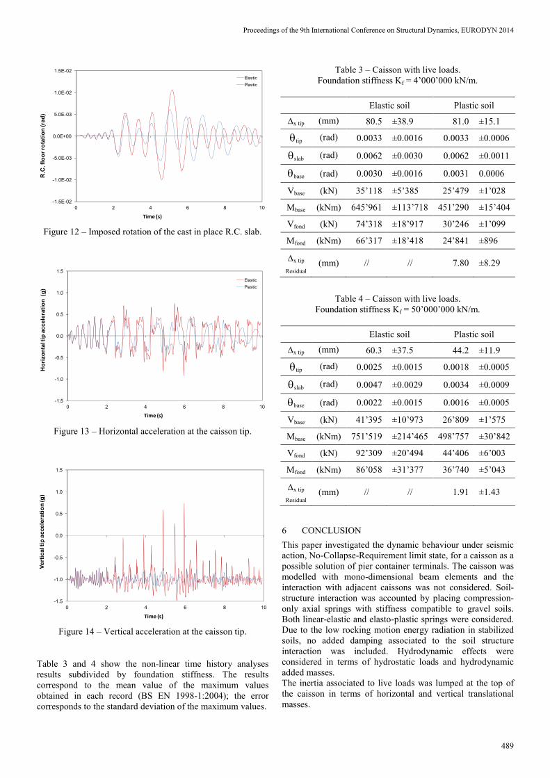
Regarding non-linear time history analyses, the results are reported in terms of the mean of the maximum values obtained in each record set: the horizontal and vertical components of the selected records are applied simultaneously at the caisson foundation. The relevant data are the maximum base shear and overturning moment, the maximum displacement and rotation at the top of the caisson, the maximum rotation required at the edges of the cast in place R.C. slab, the foundation maximum shear and bending moment at the intersection with the caisson base. In order to highlight the dynamic non-linear behaviour of the caisson structure, Figures 10, 11, 12, 13 and 14 show in graphical terms the results of the caisson subjected to the earthquake record 1, considering live loads and soil axial springs with stiffness 4’000’000 kN/m in the case of linear elastic and elasto-plastic (Fy = 5’000 kN) conditions.
-50000
-40000
-30000
-20000
-10000
0
10000
20000
30000
40000
50000
-0.15 -0.10 -0.05 0.00 0.05 0.10 0.15
Sh
ear
(kN
)
Tip displacement (m)
Elastic
Plastic
Figure 10 – Base shear – tip displacement.
-6.0E-03
-4.0E-03
-2.0E-03
0.0E+00
2.0E-03
4.0E-03
6.0E-03
8.0E-03
0 2 4 6 8 10
Tip
ro
tati
on
(rad
)
Time (s)
Elastic
Plastic
Figure 11 – Rotation at the caisson tip.
Proceedings of the 9th International Conference on Structural Dynamics, EURODYN 2014
488
-1.5E-02
-1.0E-02
-5.0E-03
0.0E+00
5.0E-03
1.0E-02
1.5E-02
0 2 4 6 8 10
R.C
. flo
or
rota
tio
n (ra
d)
Time (s)
Elastic
Plastic
Figure 12 – Imposed rotation of the cast in place R.C. slab.
-1.5
-1.0
-0.5
0.0
0.5
1.0
1.5
0 2 4 6 8 10
Ho
rizo
nta
l tip
ac
ce
lera
tio
n (
g)
Time (s)
Elastic
Plastic
Figure 13 – Horizontal acceleration at the caisson tip.
-1.5
-1.0
-0.5
0.0
0.5
1.0
1.5
0 2 4 6 8 10
Ve
rtic
al t
ip a
cce
lera
tio
n (g
)
Time (s)
Figure 14 – Vertical acceleration at the caisson tip.
Table 3 and 4 show the non-linear time history analyses results subdivided by foundation stiffness. The results correspond to the mean value of the maximum values obtained in each record (BS EN 1998-1:2004); the error corresponds to the standard deviation of the maximum values.
Table 3 – Caisson with live loads. Foundation stiffness Kf = 4’000’000 kN/m.
Elastic soil Plastic soil
x tip (mm) 80.5 ±38.9 81.0 ±15.1
tip (rad) 0.0033 ±0.0016 0.0033 ±0.0006
slab (rad) 0.0062 ±0.0030 0.0062 ±0.0011
base (rad) 0.0030 ±0.0016 0.0031 0.0006
Vbase (kN) 35’118 ±5’385 25’479 ±1’028
Mbase (kNm) 645’961 ±113’718 451’290 ±15’404
Vfond (kN) 74’318 ±18’917 30’246 ±1’099
Mfond (kNm) 66’317 ±18’418 24’841 ±896
x tip
Residual(mm) // // 7.80 ±8.29
Table 4 – Caisson with live loads. Foundation stiffness Kf = 50’000’000 kN/m.
Elastic soil Plastic soil
x tip (mm) 60.3 ±37.5 44.2 ±11.9
tip (rad) 0.0025 ±0.0015 0.0018 ±0.0005
slab (rad) 0.0047 ±0.0029 0.0034 ±0.0009
base (rad) 0.0022 ±0.0015 0.0016 ±0.0005
Vbase (kN) 41’395 ±10’973 26’809 ±1’575
Mbase (kNm) 751’519 ±214’465 498’757 ±30’842
Vfond (kN) 92’309 ±20’494 44’406 ±6’003
Mfond (kNm) 86’058 ±31’377 36’740 ±5’043
x tip
Residual(mm) // // 1.91 ±1.43
6 CONCLUSION
This paper investigated the dynamic behaviour under seismic action, No-Collapse-Requirement limit state, for a caisson as a possible solution of pier container terminals. The caisson was modelled with mono-dimensional beam elements and the interaction with adjacent caissons was not considered. Soil-structure interaction was accounted by placing compression-only axial springs with stiffness compatible to gravel soils. Both linear-elastic and elasto-plastic springs were considered. Due to the low rocking motion energy radiation in stabilized soils, no added damping associated to the soil structure interaction was included. Hydrodynamic effects were considered in terms of hydrostatic loads and hydrodynamic added masses. The inertia associated to live loads was lumped at the top of the caisson in terms of horizontal and vertical translational masses.
Proceedings of the 9th International Conference on Structural Dynamics, EURODYN 2014
489
The non-linear dynamic analyses showed limited displacements of the caisson top, with higher values in the case of elasto-plastic soil with low elastic stiffness. The higher demands were recorded for finite element models including live loads and with linear-elastic soil with high stiffness. The transverse rocking motion was characterized by self-centring with negligible permanent top displacements in the case of elasto-plastic soils. The non-linear dynamic behaviour is characterized by limited uplift of the foundation relative to the soil, this uplift is responsible of the non-linearity, mainly geometric non-linearity, related to soil-structure interaction. The analyses showed high frequency acceleration spikes associated to the closing of the base gap in subsequent cycles. It is worth noting that the amount and magnitude of these acceleration spikes is influenced by the finite element modelling and is emphasized by adopting elastic structural elements, linear-elastic soil base-springs with high stiffness and by lumping the seismic mass associated to live loads at the caisson’s top. The amount and magnitude of high frequency acceleration spikes will decrease by modelling the non-linearity of structural elements and of the soil springs (especially radiation damping) and by distributing live loads seismic masses. On the basis of the analyses results it is possible to confirm the stability of the caissons in the transverse direction and the suitability of this solution for seismic applications.
REFERENCES
[1] Ambraseys N, Smit P, Douglas J, Margaris B, Sigbjornsson R, Olafsson S, Suhadolc P and Costa G, Internet-Site for European Strong-Motion Data, 2004, Bollettino di Geofisica Teorica ed Applicata 45(3): 113-129.
[2] BS EN 1998-1:2004 - Eurocode 8 - Design of Structures for Earthquake Resistance. Part 1: General rules, seismic actions and rules for buildings.
[3] BS EN 1998-2:2005 - Eurocode 8 - Design of Structures for Earthquake Resistance. Part 2: Bridges.
[4] FEMA 356 Prestandard and Commentary for the Seismic Rehabilitation of Buildings, 2000, Federal Emergency Management Agency Washington, D.C.
[5] Goyal A., Chopra A. K., Simplified Evaluation of Added Hydrodynamic Mass for Intake Towers, J. Eng. Mech. 1989.115:1393-1412.
[6] Newman J.N., Marine Hydrodynamics, 1977, The MIT Press, Cambridge, MA - USA.
Proceedings of the 9th International Conference on Structural Dynamics, EURODYN 2014
490


![Statement of Reasons - Certain waterproof footwear · [18] For purposes ofthis complaint, "waterproof'is defined as follows: Ifthe exterior ofthe bottom is partially submerged in](https://img.pdfslide.net/doc/110x75/60277342960c30332a72128d/statement-of-reasons-certain-waterproof-footwear-18-for-purposes-ofthis-complaint.jpg)