Embed Size (px)
Citation preview

Seismic Performance of Precast Concrete Bents used for Accelerated Bridge
Construction
Bijan Khaleghi1
Abstract
Ductility of precast prestressed girder bridges can be achieved by proper detailing of pier
diaphragm through extended strands, column bars, and joint reinforcement. Extended strands
at intermediate crossbeams are used to connect the ends of girders with diaphragms and resist
loads from creep effects, shrinkage effects, and seismic positive moments. This paper
describes the development and implementation of a precast concrete bridge bent system
suitable for accelerated bridge construction in high seismic zones. At the base of the bent, the
column is connected to a spread footing using a socket connection, while at the top the
column is joined to the cap beam using bars grouted in ducts. In both cases the connection
was verified by testing before the system was implemented. This paper describes the
development, experimental validation, and implementation of a precast concrete bridge bent
system that is intended to meet those challenges. A precast concrete bridge bent system is
presented that is conceptually simple, can be constructed rapidly, and offers excellent seismic
performance.
Introduction
Seismic design of precast concrete bridges begins with a global analysis of the response of
the structure to earthquake loadings and a detailed evaluation of connections between precast
girders and connections between the superstructure and the supporting substructure. Ductile
behavior is desirable under earthquake loadings for both the longitudinal and transverse
directions of the bridge. Further, the substructure must be made to either protect the
superstructure from force effects due to ground motions through fusing or plastic hinging, or
to transmit the inertial forces that act upon the bridge to the ground through a continuous load
path.
Connections in precast concrete substructures are typically made at the beam-column and
column-foundation interfaces to facilitate fabrication and transportation. However, for
structures in seismic regions, those interfaces represent locations of high moments and shears
and large inelastic cyclic strain reversals. Devising connections that can accommodate
inelastic cyclic deformations and are readily constructible is the primary challenge for ABC
in seismic regions.
Performance Criteria For Prestressed Girder Ordinary Bridges
Designing for life safety means that significant damage can result. Significant damage
includes permanent offsets and damage between approach structures and the bridge
superstructure, and between spans at expansion joints, permanent changes in bridge span
lengths, and permanent the basis of their stiffness distribution factors. This moment
_________________________________________________________________________
1 State Bridge Design Engineer, Washington State Department of Transportation, Bridge and
Structures Office

displacements at the top of bridge columns. Damage also consists of severe concrete
cracking, reinforcement yielding and buckling, major spalling of concrete and severe
cracking of the bridge deck slab. These conditions may require closure of the bridge to repair
the damages. Partial or complete replacement of columns may be required in some cases. For
sites with lateral flow due to liquefaction, piles and shafts may suffer significant inelastic
deformation, and consequently, partial or complete replacement of the columns, piles and
shafts may be necessary. If replacement of columns or other components is to be avoided, a
design strategy that produces minimal or moderate damage, such as seismic isolation or a
control and reparability design concept, should be used. Figure 1 shows the connection
concept is commonly used by WSDOT for bridges in moderate and high seismic zones.
Girders and deck slab are continuous at piers with girders framed into the pier diaphragm.
Such structures are thought to exhibit behavior as a continuous superstructure with a fixed
moment resistant connection to the substructure.
Figure 1: Pier with Girders Framed into the Pier Diaphragm
Plastic hinges form before any other failure due to overstress or instability in either the
overall structure, or in the foundation, or both. Plastic hinges are permitted only at locations
in columns where they can be readily inspected and repaired. Superstructure and substructure
components and their connections to columns that are not designed to yield are rather
designed to resist overstrength moments and shears of ductile columns. The plastic moment
capacity for reinforced concrete columns is determined using a moment curvature section
analysis, taking into account the expected yield strength of the materials, the confined
concrete properties, and the strain-hardening effects of the longitudinal reinforcement.
Capacity-protected members such as bent caps, joints at top and bottom of column, and
integral superstructure elements that are adjacent to the plastic hinge locations are designed to
remain essentially elastic when the plastic hinge reaches its overstrength moment capacity.
The superstructure is designed as a capacity protected member. Any moment demand caused
by dead load or secondary prestress effects in case of continuous tendons over piers is
distributed to the entire width of the superstructure. The column overstrength moment, in
addition to the moment induced due to the eccentricity between the plastic hinge location and
the center of gravity of the superstructure, is distributed to the spans framing into the bent on

demand is considered within the effective width of the superstructure.
Positive Moment Connection At Pier Diaphragms
The procedure used to calculate the required number of extended strands is described in this
section. Calculations assume the development of the tensile strength of the strands at ultima te
loads. Strands used for this purpose must be developed within the short distance between the
two girder ends.2
The design moment at the center of gravity of the superstructure, Mpo CG is calculated using
the following equation:
(1)
Where:
= plastic overstrength moment at top of column, ft-kips
= plastic overstrength moment at base of column, ft-kips
h = distance from top of column to c.g. of superstructure, ft
Lc = column clear height used to determine overstrength shear associated
with the overstrength moments, ft
This moment is resisted by the bent cap through torsion. The torsional capacity of the bent cat
shall be investigated. The torsion in the bent cap is distributed into the superstructure based
on the relative flexibility of the superstructure and the bent cap. Hence, the superstructure
does not resist column overstrength moments uniformly across its width. To account for this,
an effective width approximation is used, where the maximum resistance per unit of
superstructure width of the actual structure is distributed over an equivalent effective width to
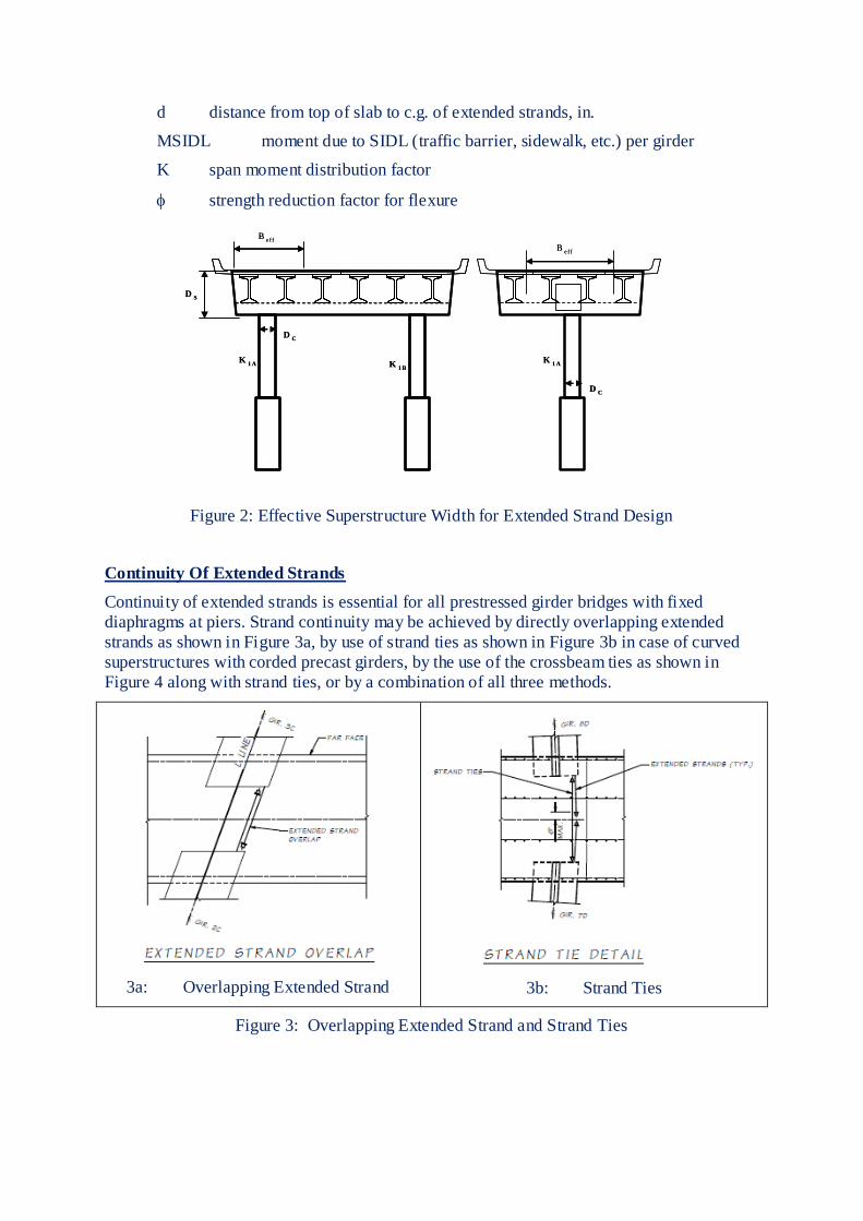
provide an equivalent resistance3. The equivalent width concept is illustrated in Figure 2.
For concrete bridges, with the exception of box girders and solid superstructures, this
effective width can be calculated as follows:
Beff = Dc + Ds (2)
Where:
Dc diameter of column
Ds depth of superstructure including cap beam
Total number of extended straight strands, Nps, needed to develop the required moment
capacity at the end of girder is based on the yield strength of the strands:
(3)
where:
Aps area of each extended strand, in.2
fpy yield strength of prestressing steel, ksi
top
poM
Base
poM
h
L
MMMM
c
Base
po
top
potop
po
CG
po
dfA
MKMN
pyps
SIDLseips
9.0
1 12
d distance from top of slab to c.g. of extended strands, in.
MSIDL moment due to SIDL (traffic barrier, sidewalk, etc.) per girder
K span moment distribution factor
strength reduction factor for flexure
Figure 2: Effective Superstructure Width for Extended Strand Design
Continuity Of Extended Strands
Continuity of extended strands is essential for all prestressed girder bridges with fixed
diaphragms at piers. Strand continuity may be achieved by directly overlapping extended
strands as shown in Figure 3a, by use of strand ties as shown in Figure 3b in case of curved
superstructures with corded precast girders, by the use of the crossbeam ties as shown in
Figure 4 along with strand ties, or by a combination of all three methods.
3a: Overlapping Extended Strand
3b: Strand Ties
Figure 3: Overlapping Extended Strand and Strand Ties
K1 A
K1 A
DC
K1 B
DS
DC
Be ff
Be ff
K1 A
K1 A
DC
K1 B
DS
DC
Be ff
Be ff
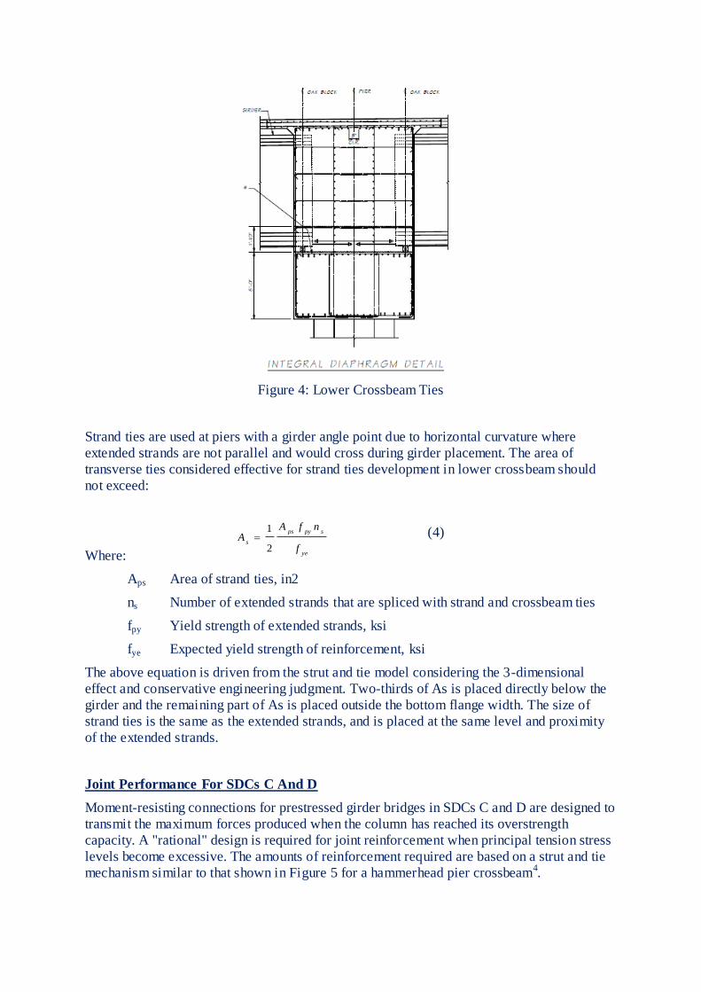
Figure 4: Lower Crossbeam Ties
Strand ties are used at piers with a girder angle point due to horizontal curvature where
extended strands are not parallel and would cross during girder placement. The area of
transverse ties considered effective for strand ties development in lower crossbeam should
not exceed:
(4)
Where:
Aps Area of strand ties, in2
ns Number of extended strands that are spliced with strand and crossbeam ties
fpy Yield strength of extended strands, ksi
fye Expected yield strength of reinforcement, ksi
The above equation is driven from the strut and tie model considering the 3-dimensional
effect and conservative engineering judgment. Two-thirds of As is placed directly below the
girder and the remaining part of As is placed outside the bottom flange width. The size of
strand ties is the same as the extended strands, and is placed at the same level and proximity
of the extended strands.
Joint Performance For SDCs C And D
Moment-resisting connections for prestressed girder bridges in SDCs C and D are designed to
transmit the maximum forces produced when the column has reached its overstrength
capacity. A "rational" design is required for joint reinforcement when principal tension stress
levels become excessive. The amounts of reinforcement required are based on a strut and tie
mechanism similar to that shown in Figure 5 for a hammerhead pier crossbeam4.
ye
spyps
s
f
nfAA
2
1

Figure 5: Strut and Tie Model of Intermediate Diaphragm
For precast prestressed girder bridges in SDCs C and D with fixed diaphragms at piers, all
column longitudinal reinforcement should be extended into the cast-in-place concrete
diaphragm on top of the crossbeam. For bridges in SDC B with fixed diaphragms at piers,
column longitudinal reinforcement can be terminated at top of lower crossbeam. Column
longitudinal reinforcement can be terminated at top of lower crossbeam in all SDCs if
analysis shows that plastic hinging will not occur at the top of column under the design
earthquake.
In case of interference, column longitudinal reinforcement obstructing the extended strands
should be terminated at the top of the lower crossbeam, and should be replaced with the
equivalent full height stirrups extending from the lower to upper crossbeam within the
effective zone. The effective zone is defined as the width Dc+Ds1 for columns without
headed bars and Dc+2 Ds1 for columns with headed bars, where Dc is the column width or
diameter, and Ds1 is the depth of lower crossbeam. Headed bars are only used if the depth of
the lower crossbeam is less than 1.25 times the tension development length of column
longitudinal reinforcement.
ASTM A706 Grade 80 reinforcing steel may be used for capacity-protected members such as
footings, bent caps, oversized shafts, joints, and integral superstructure elements that are
adjacent to the plastic hinge locations if the expected nominal moment capacity is determined
by strength design based on the expected concrete compressive strength with a maximum
usable strain of 0.003, and a reinforcing steel yield strength of 80 ksi with a maximum usable
strain of 0.090 for #10 bars and smaller, and 0.060 for #11 bars and larger. The resistance
factors for seismic related calculations are taken as 0.90 for shear and 1.0 for bending. ASTM
A706 Grade 80 reinforcing steel should not be used for transverse reinforcement in members
resisting torsion. The applicability of AASHTO SGS is limited to grade 60 ksi reinforcing
steel. Since the suitability of ASTM A706 Grade 80 ksi reinforcing bars for ductility and

confinement has not been tested, the applicability should be limited only to non-ductile
elements.
Design Specifications And Guidelines
There are two methods for seismic design of bridges: force-based design by the American
Association of State Highway and Transportation Officials’ AASHTO LRFD Bridge Design
Specifications1 and displacement-based design by the AASHTO Guide Specification for
LRFD Seismic Bridge Design.
WSDOT’s seismic design is based on the AASHTO guide specification modified by the
WSDOT Bridge Design Manual. Displacement-based design is intended to achieve a no-
collapse condition for bridges using one level of seismic safety evaluation. The fundamental
design principle is capacity protection, where selected elements are identified for plastic
hinging while others are protected against potential damage by providing them with sufficient
strength to resist the forces consistent with the plastic hinge strengths.
Displacement-based analysis is an inelastic static analysis using the expected material
properties of the modeled members. This methodology, commonly referred to as pushover
analysis, is used to determine the reliable displacement capacity of a structure as it reaches its
limit of structural stability4.
The procedure outlined in the following steps is for displacement-based analysis and is
applicable to bridges made of precast concrete components. The underlying assumption is
that the displacement demand obtained from linear-elastic response spectrum analysis can be
used to estimate the displacement demand even if there is considerable nonlinear plastic
hinging.
1. Develop an analytical model with appropriate foundation stiffness and yielding member
stiffness based on moment-curvature relationships. For capacity-protected members,
including the precast concrete girder-to-diaphragm connection, consider the properties of
the cracked section.
2. Perform linear elastic response spectrum analysis of the bridge based on design
acceleration spectra given in national or local specifications.
3. Determine the lateral and longitudinal displacement demands at each pier, including
appropriate directional combinations.
4. Perform pushover analysis of each pier in the local transverse longitudinal directions. For
this purpose, the plastic hinging behavior for each column must be included, and this will
generally be based on the moment-curvature relationships used in step 1. Use foundation
stiffness that are consistent with those used in the displacement demand model.
5. Compare the total displacement capacity of the pier, based on concrete and steel strain
limits, with the displacement demand. Also compare the displacement ductility demand
with the permissible capacity. If either the displacement or ductility capacity is
insufficient, revise accordingly.
6. Capacity protect the superstructure and foundation for the overstrength forces (typically,
20% higher than the plastic capacity of the columns) to make sure that plastic hinges
occur within the column. Capacity protect the column in shear for these same
overstrength forces.
Implementation – From Research To Practice
Figure 6 shows the configuration of the bridge bent system that was developed. It consists of

a cast-in-place concrete spread footing, a precast concrete column, and a precast concrete
first-stage cap beam. The second-stage cap beam is cast in place, just as it would be in a fully
cast-in-place concrete system5.
Figure 6. Precast concrete bent system configuration.
Figure 7. Previous use of precast concrete cap beam that used in Washington State.
The socket concept was used previously in Washington in a modified form. In that case, the
contract called for cast-in-place concrete columns, but the contractor elected to precast them
on-site and use a socket connection to save time. The footing was 6 ft (1.8 m) thick, the
columns were 4 ft (1.2 m) square, and the connection between them was made by roughening
the column surface locally and adding horizontal form-saver bars. Those bars screwed into
threaded couplers embedded in the face of the column within the depth of the footing to
provide shear friction across the interface and were inserted after the column had been
placed.
The column-to-cap beam connection was made with vertical bars projecting from the column
that were grouted into ducts in the cap beam. Again, this concept has been used previously,
but primarily in regions of low seismicity where the number of bars needed for the
connection was small and the loading was not cyclic. The concept was also used once in the
high seismic zone in western Washington. The bridge site is in a congested urban area with
high visibility from the traveling public and high scrutiny from associated municipalities. To
open the bridge as quickly as possible, the contractor proposed precasting the cap beams for

the intermediate piers instead of casting them in place as shown on the contract plans. This
change saved the owner and the contractor several weeks. The columns were reinforced with
the same fourteen no. 14 (43M) column bars as on the original plans. They were grouted into
4 in. (100 mm) galvanized steel ducts that were placed in the precast concrete cap beam using
a template. The cap beams weighed approximately 200 kip (890 kN) each and were precast
on the ground adjacent to the columns.
The material characteristics in the tests included ASTM A70610 Grade 60 (410 MPa)
deformed reinforcing bars, corrugated galvanized pipes, and cementitious grout with
compressive strength of 8.0 ksi (56 MPa). The corrugated pipes are available in diameters
from 6 in. (150 mm) to 12 ft (3.7 m). The pipes have thicker walls, deeper corrugations, and
potentially better bond and confinement properties than those of standard posttensioning
ducts.
Figure 8 summarizes the results of the pullout tests. It shows the bar stress at failure plotted
against the ratio of embedment length to bar diameter le/dbto permit comparison among
different bar sizes. In the nomenclature for the tests, 18N06 means a no. 18 (57M) bar with
no fiber in the grout embedded 6 bar diameters. The letter F signifies fibers in the grout, N
signifies no fibers, and S indicates a failure near the surface, which was controlled by a
tension failure cone in the concrete surrounding the duct, rather than a shear failure in the
grout.
The fibers were polypropylene with a dosage of 3 lb/yd3 (1.8 kg/m3). They were used in
some pull- out specimens, but they adversely affected the grout strength and therefore the
anchorage performance, so they were not used in the final connection. A non- linear
numerical model was calibrated against the test results, and the model’s results are also
shown. Finally, separate lines show the nominal yield and ultimate stresses of the bars.
Three outcomes can be seen from the tests. First, the bar stress at failure is essentially
proportional to le/db. This implies that the bond stress is constant along the bar and the same
in all specimens and that failure was by plastic shear failure in the grout. Visual observations
supported that finding. Second, the bar can be anchored to reach yield and fracture if the
embedment lengths are 6db and 10db, respectively.
Once the anchorage properties under monotonic tension loading had been established,
column-to-cap beam connection tests were conducted under cyclic lateral loading. Figure 10
shows a typical test. The specimens were tested upside down so that the cap beam could be
bolted to the base of the test rig. The specimens were 42% scale, so the 20 in. (500 mm) test
column represented a 48 in. (1200 mm) prototype. The goal was to investigate the behavior
of complete grouted bar connections under cyclic lateral load6.

Figure 8. Grouted bar-duct pullout test results. Note: db = bar diameter; le = embedment
length. 1 ksi = 6.895 MPa.
The cyclic tests were performed on three variations of the large bar precast concrete system,
as well as a typical cast-in-place concrete connection for comparison. All three variations of
the proposed system performed satisfactorily to a drift ratio of 5.5%, after which longitudinal
bar buckling and fracture occurred. This value is approximately three times the demand
expected in a major earthquake and is comparable to the value achieved with a cast-in- place
concrete system. In all cases the failure occurred in the plastic hinge region of the column.
This finding suggests that the large-bar, large-duct precast concrete system has sufficient
strength and ductility capacity for all foreseeable seismic demands and system performance is
similar to that of cast-in-place concrete construction.
Figure 9. Construction and testing of precast concrete column-to-footing connection.
Site implementations- From Research to Practice
Figures 10 through 12 show the details of this project. The bridge features include the

following:
• unique socket connection of precast concrete column to footing
• precast concrete columns fabricated in segments and joined by bars grouted in ducts
• precast concrete cap beam made in two segments that were joined by a cast-in-place
concrete closure
• precast concrete superstructure with cast-in-place concrete closure at intermediate pier
Figure 10. Bridge layout for demonstration project.
Figure 11. Demonstration bridge column details for elevation.
The construction sequence for placement of the precast concrete superstructure at the
intermediate pier is as follows:
• Place precast concrete girders on oak blocks.
• Install girder bracing as necessary.
• Complete welded ties between girders.
• Join flange shear keys and grout intermediate diaphragms.
• Place slab reinforcement and cast concrete.
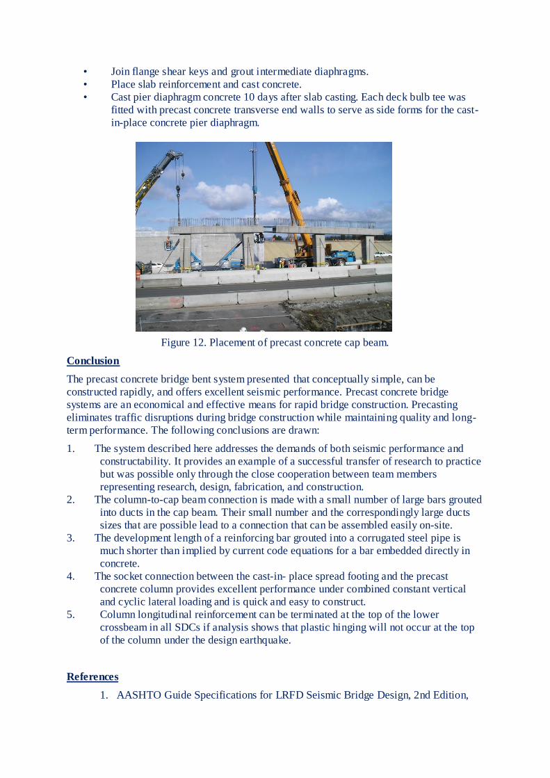
• Cast pier diaphragm concrete 10 days after slab casting. Each deck bulb tee was
fitted with precast concrete transverse end walls to serve as side forms for the cast-
in-place concrete pier diaphragm.
Figure 12. Placement of precast concrete cap beam.
Conclusion
The precast concrete bridge bent system presented that conceptually simple, can be
constructed rapidly, and offers excellent seismic performance. Precast concrete bridge
systems are an economical and effective means for rapid bridge construction. Precasting
eliminates traffic disruptions during bridge construction while maintaining quality and long-
term performance. The following conclusions are drawn:
1. The system described here addresses the demands of both seismic performance and
constructability. It provides an example of a successful transfer of research to practice
but was possible only through the close cooperation between team members
representing research, design, fabrication, and construction.
2. The column-to-cap beam connection is made with a small number of large bars grouted
into ducts in the cap beam. Their small number and the correspondingly large ducts
sizes that are possible lead to a connection that can be assembled easily on-site.
3. The development length of a reinforcing bar grouted into a corrugated steel pipe is
much shorter than implied by current code equations for a bar embedded directly in
concrete.
4. The socket connection between the cast-in- place spread footing and the precast
concrete column provides excellent performance under combined constant vertical
and cyclic lateral loading and is quick and easy to construct.
5. Column longitudinal reinforcement can be terminated at the top of the lower
crossbeam in all SDCs if analysis shows that plastic hinging will not occur at the top
of the column under the design earthquake.
References
1. AASHTO Guide Specifications for LRFD Seismic Bridge Design, 2nd Edition,

2011.
2. Bridge Design Manual, Publication No. M23-50, Washington State Department of
Transportation, Bridge and Structures Office, Olympia, Washington, 2010.
3. Khaleghi, B. 2010. “Washington State Department of Transportation Plan for
Accelerated Bridge Construction.” Transportation Research Record: Journal of the
Transportation Research Board (2200): 3–11.
4. Marsh, M. L., M. Wernli, B. E. Garrett, J. F. Stanton, M. O. Eberhard, and M. D.
Weinert. 2011. “System Performance of Accelerated Bridge Construction (ABC)
Connections in Moderate-to-High Seismic Regions.” NCHRP (National
Cooperative Highway Research Program) Synthesis of Highway Practice report
698. Washington, DC: NCHRP.
5. WSDOT Highways for LIFE (HfL) Project. “US 12 over I-5, Grand Mound to
Maytown Interchange Phase 2 Bridge 12/118 Replacement.” WSDOT Olympic
Region.
6. Stanton, J. F., M. O. Eberhard, M. L. Marsh, B. Khaleghi, O. S. Haraldsson, T. M.
Janes, H. Viet Tran, and P. Davis. 2012. “Bent on Safety: New Design Toughens
ABC During Seismic Events.” Roads and Bridges 50 (1): 36–41.