Embed Size (px)
Citation preview
Seismic pounding mitigation of a modern heritage R/C bell tower
F. Pratesi1, S. Sorace2 & G. Terenzi1 1Department of Civil and Environmental Engineering, University of Florence, Italy 2Department of Civil Engineering and Architecture, University of Udine, Italy
Abstract
Pounding is one of the greatest sources of seismic vulnerability of pre-normative R/C structures, as they have often been built at poor distance from adjacent buildings. The effects of pounding can be particularly severe in slender modern R/C heritage structures, including civic or bell towers. An emblematic case study falling in this class of structures, i.e. a monumental R/C bell tower constructed in the early 1960s to replace the former 19th century tower of the Chiesa del Sacro Cuore in Florence, is analyzed in this paper. In order to assess the effects of pounding, a non-linear dynamic finite element enquiry was carried out by simulating collisions with a multi-link viscoelastic contact model originally implemented in this study. The survey results show that pounding affects the seismic response of the bell tower and the church as early as an input seismic action scaled at the amplitude of the normative basic design earthquake level. A retrofit hypothesis to prevent pounding is then proposed, which consists in linking the two structures by means of a pair of fluid-viscous dampers. The technical implementation of this rehabilitation strategy and the benefits induced in the response of the bell tower are discussed in detail in the paper. Keywords: seismic pounding, modern architectural heritage, historical research, structural assessment, seismic retrofit, dampers.
1 Introduction
A significant stock of modern heritage buildings is constituted by reinforced concrete (R/C) structures designed and erected with no – or very limited –
Structural Studies, Repairs and Maintenance of Heritage Architecture XIII 303
www.witpress.com, ISSN 1743-3509 (on-line) WIT Transactions on The Built Environment, Vol 131, © 2013 WIT Press
doi:10.2495/STR130261
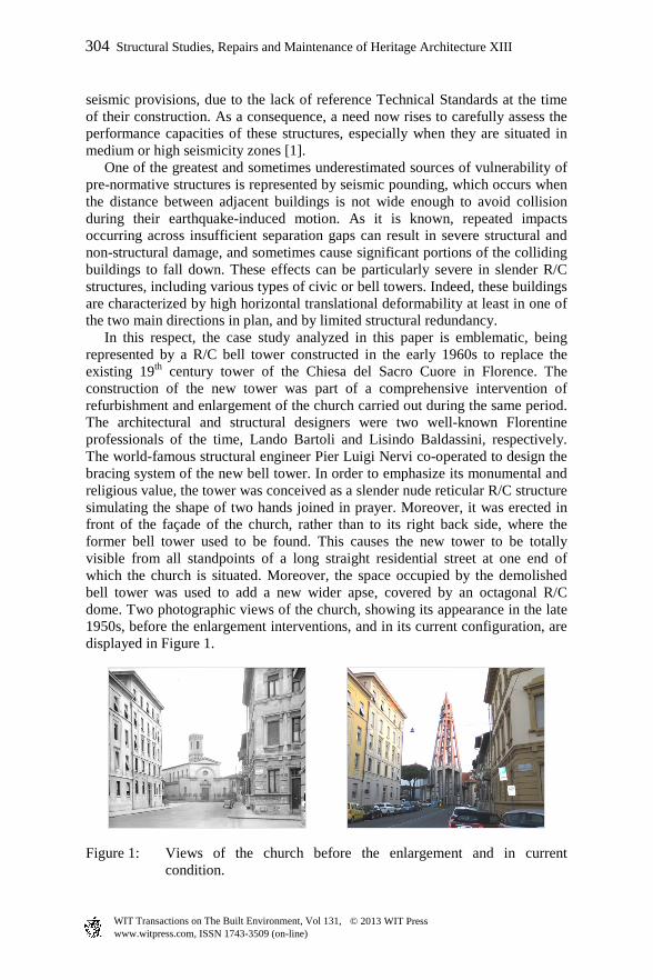
seismic provisions, due to the lack of reference Technical Standards at the time of their construction. As a consequence, a need now rises to carefully assess the performance capacities of these structures, especially when they are situated in medium or high seismicity zones [1]. One of the greatest and sometimes underestimated sources of vulnerability of pre-normative structures is represented by seismic pounding, which occurs when the distance between adjacent buildings is not wide enough to avoid collision during their earthquake-induced motion. As it is known, repeated impacts occurring across insufficient separation gaps can result in severe structural and non-structural damage, and sometimes cause significant portions of the colliding buildings to fall down. These effects can be particularly severe in slender R/C structures, including various types of civic or bell towers. Indeed, these buildings are characterized by high horizontal translational deformability at least in one of the two main directions in plan, and by limited structural redundancy. In this respect, the case study analyzed in this paper is emblematic, being represented by a R/C bell tower constructed in the early 1960s to replace the existing 19th century tower of the Chiesa del Sacro Cuore in Florence. The construction of the new tower was part of a comprehensive intervention of refurbishment and enlargement of the church carried out during the same period. The architectural and structural designers were two well-known Florentine professionals of the time, Lando Bartoli and Lisindo Baldassini, respectively. The world-famous structural engineer Pier Luigi Nervi co-operated to design the bracing system of the new bell tower. In order to emphasize its monumental and religious value, the tower was conceived as a slender nude reticular R/C structure simulating the shape of two hands joined in prayer. Moreover, it was erected in front of the façade of the church, rather than to its right back side, where the former bell tower used to be found. This causes the new tower to be totally visible from all standpoints of a long straight residential street at one end of which the church is situated. Moreover, the space occupied by the demolished bell tower was used to add a new wider apse, covered by an octagonal R/C dome. Two photographic views of the church, showing its appearance in the late 1950s, before the enlargement interventions, and in its current configuration, are displayed in Figure 1.
Figure 1: Views of the church before the enlargement and in current
condition.
304 Structural Studies, Repairs and Maintenance of Heritage Architecture XIII
www.witpress.com, ISSN 1743-3509 (on-line) WIT Transactions on The Built Environment, Vol 131, © 2013 WIT Press
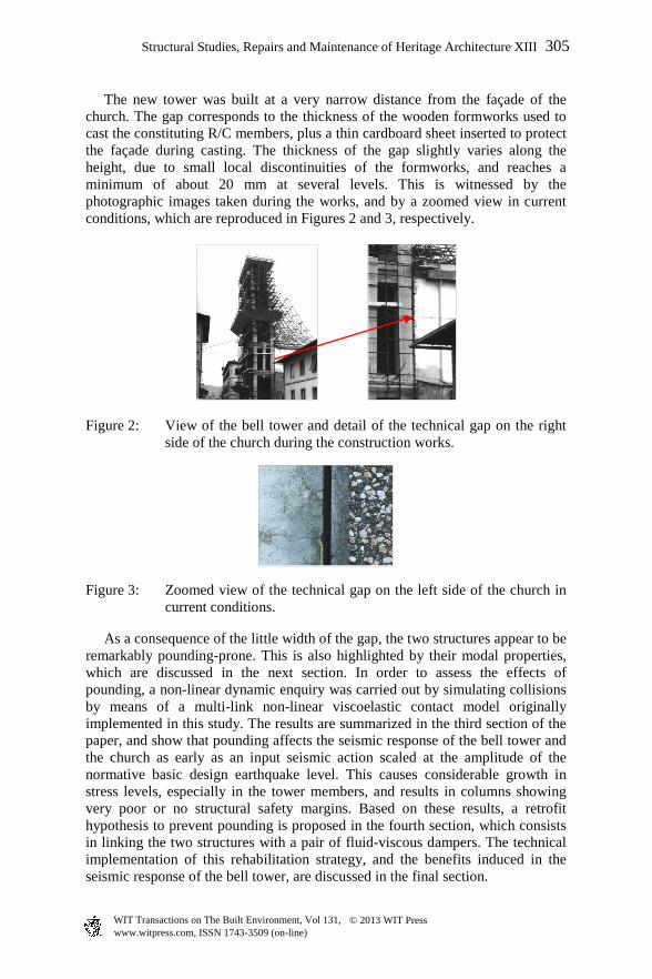
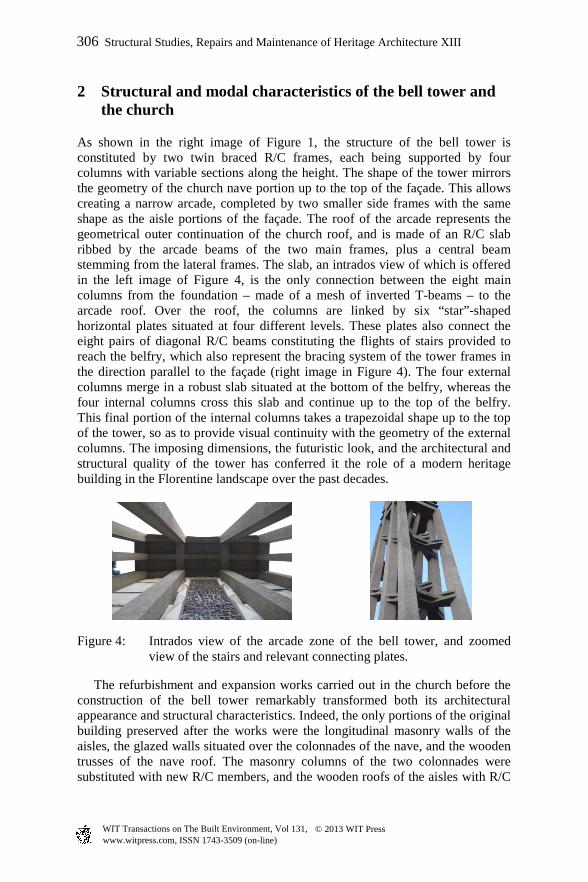
The new tower was built at a very narrow distance from the façade of the church. The gap corresponds to the thickness of the wooden formworks used to cast the constituting R/C members, plus a thin cardboard sheet inserted to protect the façade during casting. The thickness of the gap slightly varies along the height, due to small local discontinuities of the formworks, and reaches a minimum of about 20 mm at several levels. This is witnessed by the photographic images taken during the works, and by a zoomed view in current conditions, which are reproduced in Figures 2 and 3, respectively.
Figure 2: View of the bell tower and detail of the technical gap on the right
side of the church during the construction works.
Figure 3: Zoomed view of the technical gap on the left side of the church in current conditions.
As a consequence of the little width of the gap, the two structures appear to be remarkably pounding-prone. This is also highlighted by their modal properties, which are discussed in the next section. In order to assess the effects of pounding, a non-linear dynamic enquiry was carried out by simulating collisions by means of a multi-link non-linear viscoelastic contact model originally implemented in this study. The results are summarized in the third section of the paper, and show that pounding affects the seismic response of the bell tower and the church as early as an input seismic action scaled at the amplitude of the normative basic design earthquake level. This causes considerable growth in stress levels, especially in the tower members, and results in columns showing very poor or no structural safety margins. Based on these results, a retrofit hypothesis to prevent pounding is proposed in the fourth section, which consists in linking the two structures with a pair of fluid-viscous dampers. The technical implementation of this rehabilitation strategy, and the benefits induced in the seismic response of the bell tower, are discussed in the final section.
Structural Studies, Repairs and Maintenance of Heritage Architecture XIII 305
www.witpress.com, ISSN 1743-3509 (on-line) WIT Transactions on The Built Environment, Vol 131, © 2013 WIT Press
2 Structural and modal characteristics of the bell tower and the church
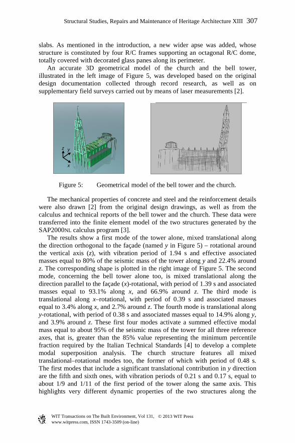
As shown in the right image of Figure 1, the structure of the bell tower is constituted by two twin braced R/C frames, each being supported by four columns with variable sections along the height. The shape of the tower mirrors the geometry of the church nave portion up to the top of the façade. This allows creating a narrow arcade, completed by two smaller side frames with the same shape as the aisle portions of the façade. The roof of the arcade represents the geometrical outer continuation of the church roof, and is made of an R/C slab ribbed by the arcade beams of the two main frames, plus a central beam stemming from the lateral frames. The slab, an intrados view of which is offered in the left image of Figure 4, is the only connection between the eight main columns from the foundation – made of a mesh of inverted T-beams – to the arcade roof. Over the roof, the columns are linked by six “star”-shaped horizontal plates situated at four different levels. These plates also connect the eight pairs of diagonal R/C beams constituting the flights of stairs provided to reach the belfry, which also represent the bracing system of the tower frames in the direction parallel to the façade (right image in Figure 4). The four external columns merge in a robust slab situated at the bottom of the belfry, whereas the four internal columns cross this slab and continue up to the top of the belfry. This final portion of the internal columns takes a trapezoidal shape up to the top of the tower, so as to provide visual continuity with the geometry of the external columns. The imposing dimensions, the futuristic look, and the architectural and structural quality of the tower has conferred it the role of a modern heritage building in the Florentine landscape over the past decades.
Figure 4: Intrados view of the arcade zone of the bell tower, and zoomed view of the stairs and relevant connecting plates.
The refurbishment and expansion works carried out in the church before the construction of the bell tower remarkably transformed both its architectural appearance and structural characteristics. Indeed, the only portions of the original building preserved after the works were the longitudinal masonry walls of the aisles, the glazed walls situated over the colonnades of the nave, and the wooden trusses of the nave roof. The masonry columns of the two colonnades were substituted with new R/C members, and the wooden roofs of the aisles with R/C
306 Structural Studies, Repairs and Maintenance of Heritage Architecture XIII
www.witpress.com, ISSN 1743-3509 (on-line) WIT Transactions on The Built Environment, Vol 131, © 2013 WIT Press
slabs. As mentioned in the introduction, a new wider apse was added, whose structure is constituted by four R/C frames supporting an octagonal R/C dome, totally covered with decorated glass panes along its perimeter. An accurate 3D geometrical model of the church and the bell tower, illustrated in the left image of Figure 5, was developed based on the original design documentation collected through record research, as well as on supplementary field surveys carried out by means of laser measurements [2].
Figure 5: Geometrical model of the bell tower and the church.
The mechanical properties of concrete and steel and the reinforcement details were also drawn [2] from the original design drawings, as well as from the calculus and technical reports of the bell tower and the church. These data were transferred into the finite element model of the two structures generated by the SAP2000NL calculus program [3]. The results show a first mode of the tower alone, mixed translational along the direction orthogonal to the façade (named y in Figure 5) – rotational around the vertical axis (z), with vibration period of 1.94 s and effective associated masses equal to 80% of the seismic mass of the tower along y and 22.4% around z. The corresponding shape is plotted in the right image of Figure 5. The second mode, concerning the bell tower alone too, is mixed translational along the direction parallel to the façade (x)-rotational, with period of 1.39 s and associated masses equal to 93.1% along x, and 66.9% around z. The third mode is translational along x–rotational, with period of 0.39 s and associated masses equal to 3.4% along x, and 2.7% around z. The fourth mode is translational along y-rotational, with period of 0.38 s and associated masses equal to 14.9% along y, and 3.9% around z. These first four modes activate a summed effective modal mass equal to about 95% of the seismic mass of the tower for all three reference axes, that is, greater than the 85% value representing the minimum percentile fraction required by the Italian Technical Standards [4] to develop a complete modal superposition analysis. The church structure features all mixed translational–rotational modes too, the former of which with period of 0.48 s. The first modes that include a significant translational contribution in y direction are the fifth and sixth ones, with vibration periods of 0.21 s and 0.17 s, equal to about 1/9 and 1/11 of the first period of the tower along the same axis. This highlights very different dynamic properties of the two structures along the
x
y z
Structural Studies, Repairs and Maintenance of Heritage Architecture XIII 307
www.witpress.com, ISSN 1743-3509 (on-line) WIT Transactions on The Built Environment, Vol 131, © 2013 WIT Press
potential pounding direction, as expected from their structural characteristics. In total, 20 modes are needed for the church to activate a summed modal mass greater than 85% of its total seismic mass.
3 Impact model for the analysis of pounding
The finite element analysis of pounding between bell tower and church was carried out according to a classical “contact element approach”, which offers a straightforward idealization of the problem, as it corresponds to the intuitive interpretation of the phenomenon. Impact is simulated by a contact element that is activated when the gap at rest between the structures shrinks, which allows solving the problem within the framework of an ordinary time-history response analysis [5]. The impact effects are evaluated by the coefficient of restitution r, which accounts for the energy dissipation related to the damage effects occurring during collision, defined as follows:
21
'2
'1
vv
vvr
−
−= (1)
where 1v , 2v are the approaching velocities, and '1v , '
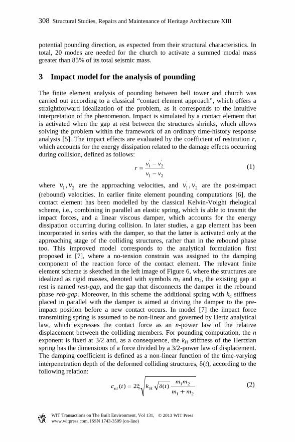
2v are the post-impact (rebound) velocities. In earlier finite element pounding computations [6], the contact element has been modelled by the classical Kelvin-Voight rhelogical scheme, i.e., combining in parallel an elastic spring, which is able to trasmit the impact forces, and a linear viscous damper, which accounts for the energy dissipation occurring during collision. In later studies, a gap element has been incorporated in series with the damper, so that the latter is activated only at the approaching stage of the colliding structures, rather than in the rebound phase too. This improved model corresponds to the analytical formulation first proposed in [7], where a no-tension constrain was assigned to the damping component of the reaction force of the contact element. The relevant finite element scheme is sketched in the left image of Figure 6, where the structures are idealized as rigid masses, denoted with symbols m1 and m2, the existing gap at rest is named rest-gap, and the gap that disconnects the damper in the rebound phase reb-gap. Moreover, in this scheme the additional spring with kd stiffness placed in parallel with the damper is aimed at driving the damper to the pre-impact position before a new contact occurs. In model [7] the impact force transmitting spring is assumed to be non-linear and governed by Hertz analytical law, which expresses the contact force as an n-power law of the relative displacement between the colliding members. For pounding computation, the n exponent is fixed at 3/2 and, as a consequence, the kH stiffness of the Hertzian spring has the dimensions of a force divided by a 3/2-power law of displacement. The damping coefficient is defined as a non-linear function of the time-varying interpenetration depth of the deformed colliding structures, δ(t), according to the following relation:
21
21Hnl )δ(ξ2)(
mm
mmtktc
+= (2)
308 Structural Studies, Repairs and Maintenance of Heritage Architecture XIII
www.witpress.com, ISSN 1743-3509 (on-line) WIT Transactions on The Built Environment, Vol 131, © 2013 WIT Press
where the impact damping ratio ξ is expressed as:
16]16)-π9([
1
2
59ξ
2
+
−=
rr
r (3)
As compared to more elaborated non-linear impact models recently proposed in literature, this model – also named “Hertdamp” for the assumption above – represents a reasonable balance point between the need to reach accurate results in the reproduction of structural pounding and to limit the computational effort. Nonetheless, the implementation of this model in commercial finite element programs is not straightforward, especially because the damping coefficient of the damper elements included in their basic libraries is generally assumed to be a constant.
Figure 6: Finite element schematization of Herzdamp model (left), and multi-damper model elaborated in this study for the analysis of pounding impact.
In order to overcome this limitation, a special “multi-damper” model constituted by an in-series assemblage of m linear dampers was devised in this study. The response of the model is based on the sequential activation and disconnection of the dampers, following the variation of the interpenetration depth δ(t). This way, the resulting equivalent damping coefficient of the assemblage becomes a function of δ(t), and expression (2) – as well as any other relation between cnl and δ(t) likely to be selected in the analysis – can be easily reproduced in piece-wise linear form in the finite element computation. The version of the multi-damper model with m=5 components is drawn in the right image of Figure 6. The activation of each damper is governed by a gap (named gap-Ci in Figure 6, with i=1,..,5 in this case, and i=1,..,m in general), to which an initial opening is assigned. As the gap closes, the damper starts to react, adding its response to the already activated dampers. Like for the non-linear damper in the Herzdamp computational model, each element is combined with a linear spring (kdi) that drives it to its pre-impact position. The remaining components of the assemblage (non-linear Hertzian spring, rest-gap, and reb-gap) are the same as in Herdamp model. An extensive numerical enquiry was carried out by varying the number of linear dampers from 3 to 9, to evaluate the relevant
kH
kd reb-gap
cnl rest-gap
m1 m2
kH
res
t-gap
c2 c3
c4 c5
kd5 kd4
kd3 kd2
kd1 re
b-
c1
m1 m2
gap -
C2
gap -
C3
gap -
C4
gap -
C5
Structural Studies, Repairs and Maintenance of Heritage Architecture XIII 309
www.witpress.com, ISSN 1743-3509 (on-line) WIT Transactions on The Built Environment, Vol 131, © 2013 WIT Press
influence on the reproduction of relation (2) [2]. The 5-damper assemblage in Figure 6 proved to bear satisfactory simulation capacities, while at the same time it helped constrain solution times within reasonable limits. Therefore, this version of the multi-damper model was incorporated at the interface between the bell tower and the church for the time-history analysis of pounding.
4 Non-linear dynamic analysis of pounding between bell tower and church
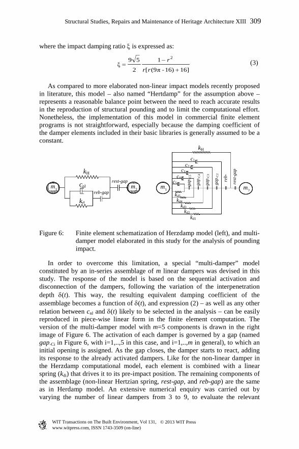
Five multi-damper elements were incorporated in the computational model at the interface between the bell tower and the church, in the positions marked by the pairs of joints denoted by letters A-A’ through E-E’ in Figure 7. These joints represent the potential physical impact spots situated on the four rear columns and at the top of the rear arcade beam, and the corresponding spots on the church façade. Details about the calibration of the characteristic parameters of the contact model are reported in [2].
Figure 7: Position of the five multi-damper elements incorporated in the computational model.
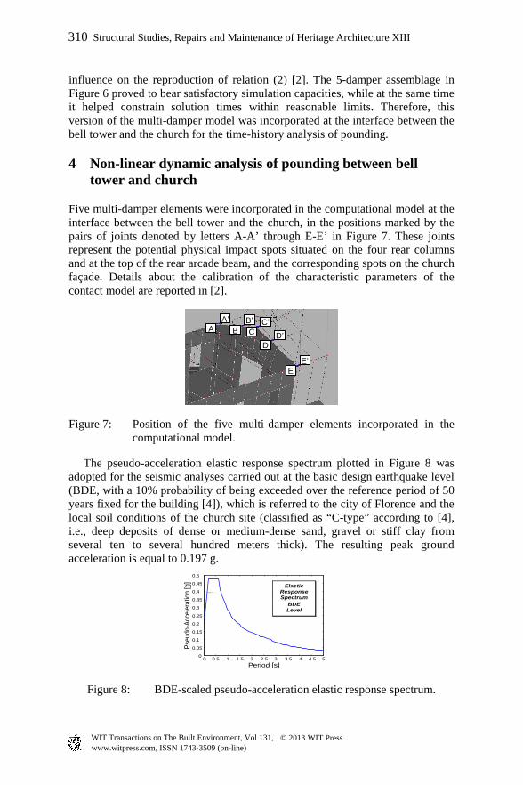
The pseudo-acceleration elastic response spectrum plotted in Figure 8 was adopted for the seismic analyses carried out at the basic design earthquake level (BDE, with a 10% probability of being exceeded over the reference period of 50 years fixed for the building [4]), which is referred to the city of Florence and the local soil conditions of the church site (classified as “C-type” according to [4], i.e., deep deposits of dense or medium-dense sand, gravel or stiff clay from several ten to several hundred meters thick). The resulting peak ground acceleration is equal to 0.197 g.
Figure 8: BDE-scaled pseudo-acceleration elastic response spectrum.
A B C D
E
A’ B’ C’ D’
E’
0 0.5 1 1.5 2 2.5 3 3.5 4 4.5 5 0
0.05
0.1
0.15
0.2
0.25
0.3
0.35
0.4
0.45
0.5
Period [s]
Pseu
do-A
ccele
ratio
n [g
]
Elastic Response Spectrum
BDE Level
310 Structural Studies, Repairs and Maintenance of Heritage Architecture XIII
www.witpress.com, ISSN 1743-3509 (on-line) WIT Transactions on The Built Environment, Vol 131, © 2013 WIT Press
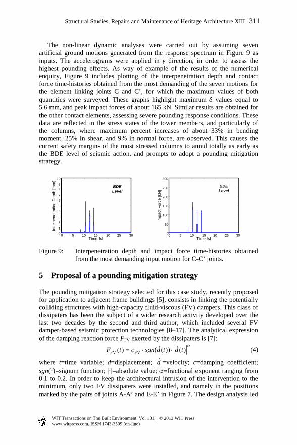
The non-linear dynamic analyses were carried out by assuming seven artificial ground motions generated from the response spectrum in Figure 9 as inputs. The accelerograms were applied in y direction, in order to assess the highest pounding effects. As way of example of the results of the numerical enquiry, Figure 9 includes plotting of the interpenetration depth and contact force time-histories obtained from the most demanding of the seven motions for the element linking joints C and C’, for which the maximum values of both quantities were surveyed. These graphs highlight maximum δ values equal to 5.6 mm, and peak impact forces of about 165 kN. Similar results are obtained for the other contact elements, assessing severe pounding response conditions. These data are reflected in the stress states of the tower members, and particularly of the columns, where maximum percent increases of about 33% in bending moment, 25% in shear, and 9% in normal force, are observed. This causes the current safety margins of the most stressed columns to annul totally as early as the BDE level of seismic action, and prompts to adopt a pounding mitigation strategy.
0 5 10 15 20 25 30 0 1
2 3 4
5
6 7 8 9
10
Time [s]
Inte
rpen
etra
tion
Dep
th [m
m]
BDE Level
0 5 10 15 20 25 30 0
50
100
150
200
250
300
Time [s]
Impa
ct F
orce
[kN
]
BDE Level
Figure 9: Interpenetration depth and impact force time-histories obtained from the most demanding input motion for C-C’ joints.
5 Proposal of a pounding mitigation strategy
The pounding mitigation strategy selected for this case study, recently proposed for application to adjacent frame buildings [5], consists in linking the potentially colliding structures with high-capacity fluid-viscous (FV) dampers. This class of dissipaters has been the subject of a wider research activity developed over the last two decades by the second and third author, which included several FV damper-based seismic protection technologies [8–17]. The analytical expression of the damping reaction force FFV exerted by the dissipaters is [7]:
α
⋅⋅= )())(()( FVFV tdtdsgnctF (4)
where t=time variable; d=displacement; d =velocity; c=damping coefficient; sgn(·)=signum function; |·|=absolute value; α=fractional exponent ranging from 0.1 to 0.2. In order to keep the architectural intrusion of the intervention to the minimum, only two FV dissipaters were installed, and namely in the positions marked by the pairs of joints A-A’ and E-E’ in Figure 7. The design analysis led
Structural Studies, Repairs and Maintenance of Heritage Architecture XIII 311
www.witpress.com, ISSN 1743-3509 (on-line) WIT Transactions on The Built Environment, Vol 131, © 2013 WIT Press
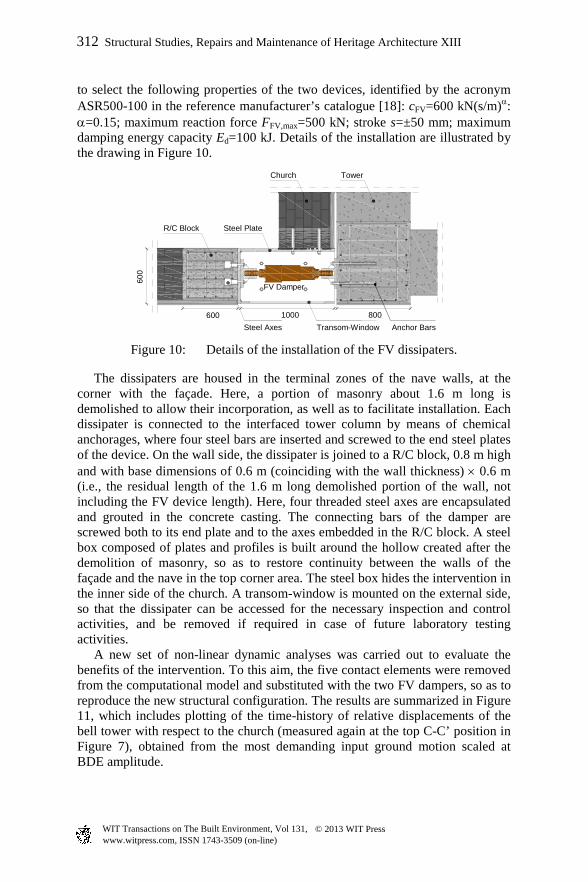
to select the following properties of the two devices, identified by the acronym ASR500-100 in the reference manufacturer’s catalogue [18]: cFV=600 kN(s/m)α: α=0.15; maximum reaction force FFV,max=500 kN; stroke s=±50 mm; maximum damping energy capacity Ed=100 kJ. Details of the installation are illustrated by the drawing in Figure 10.
Figure 10: Details of the installation of the FV dissipaters.
The dissipaters are housed in the terminal zones of the nave walls, at the corner with the façade. Here, a portion of masonry about 1.6 m long is demolished to allow their incorporation, as well as to facilitate installation. Each dissipater is connected to the interfaced tower column by means of chemical anchorages, where four steel bars are inserted and screwed to the end steel plates of the device. On the wall side, the dissipater is joined to a R/C block, 0.8 m high and with base dimensions of 0.6 m (coinciding with the wall thickness) × 0.6 m (i.e., the residual length of the 1.6 m long demolished portion of the wall, not including the FV device length). Here, four threaded steel axes are encapsulated and grouted in the concrete casting. The connecting bars of the damper are screwed both to its end plate and to the axes embedded in the R/C block. A steel box composed of plates and profiles is built around the hollow created after the demolition of masonry, so as to restore continuity between the walls of the façade and the nave in the top corner area. The steel box hides the intervention in the inner side of the church. A transom-window is mounted on the external side, so that the dissipater can be accessed for the necessary inspection and control activities, and be removed if required in case of future laboratory testing activities. A new set of non-linear dynamic analyses was carried out to evaluate the benefits of the intervention. To this aim, the five contact elements were removed from the computational model and substituted with the two FV dampers, so as to reproduce the new structural configuration. The results are summarized in Figure 11, which includes plotting of the time-history of relative displacements of the bell tower with respect to the church (measured again at the top C-C’ position in Figure 7), obtained from the most demanding input ground motion scaled at BDE amplitude.
FV Damper
Tower Church
600 1000 800 Steel Axes Transom-Window
Steel Plate R/C Block
600
Anchor Bars
312 Structural Studies, Repairs and Maintenance of Heritage Architecture XIII
www.witpress.com, ISSN 1743-3509 (on-line) WIT Transactions on The Built Environment, Vol 131, © 2013 WIT Press
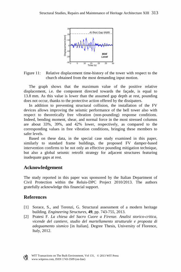
Figure 11: Relative displacement time-history of the tower with respect to the church obtained from the most demanding input motion.
The graph shows that the maximum value of the positive relative displacement, i.e. the component directed towards the façade, is equal to 13.8 mm. As this value is lower than the assumed gap depth at rest, pounding does not occur, thanks to the protective action offered by the dissipaters. In addition to preventing structural collision, the installation of the FV devices allows improving the seismic performance of the bell tower also with respect to theoretically free vibration (non-pounding) response conditions. Indeed, bending moment, shear, and normal force in the most stressed columns are about 33%, 39%, and 42% lower, respectively, as compared to the corresponding values in free vibration conditions, bringing these members to safer levels. Based on these data, in the special case study examined in this paper, similarly to standard frame buildings, the proposed FV damper-based intervention confirms to be not only an effective pounding mitigation technique, but also a global seismic retrofit strategy for adjacent structures featuring inadequate gaps at rest.
Acknowledgement
The study reported in this paper was sponsored by the Italian Department of Civil Protection within the Reluis-DPC Project 2010/2013. The authors gratefully acknowledge this financial support.
References
[1] Sorace, S., and Terenzi, G. Structural assessment of a modern heritage building. Engineering Structures, 49, pp. 743-755, 2013.
[2] Pratesi F. La chiesa del Sacro Cuore a Firenze. Analisi storico-critica, vicende del cantiere, studio del martellamento strutturale e proposta di adeguamento sismico [in Italian]. Degree Thesis, University of Florence, Italy, 2012.
0 5 10 15 20 25 30 -30
-20
-10
0
10
20
30
Time [s] D
ispl
acem
ent [
mm
]
BDE Level
At Rest Gap Width
Structural Studies, Repairs and Maintenance of Heritage Architecture XIII 313
www.witpress.com, ISSN 1743-3509 (on-line) WIT Transactions on The Built Environment, Vol 131, © 2013 WIT Press
[3] Computers and Structures Inc. SAP2000NL. Structural Analysis Programs – Theoretical and Users Manual. Version No. 14.03, CSI, Berkeley, CA, 2012.
[4] Nuove Norme Tecniche per le costruzioni [in Italian]. G.U., Rome, Italy, 2008.
[5] Sorace S., and Terenzi G. Advanced protection of seismic pounding between adjacent buildings. WASET, 71, pp. 178-184, 2012.
[6] Anagnostopoulos S. A. Pounding of buildings in series during earthquakes. Earthquake Engineering and Structural Dynamics, 16, pp. 443-456, 1988.
[7] Jankowski R. Non-linear viscoelastic modelling of earthquake-induced structural pounding. Earthquake Engineering and Structural Dynamics, 34, pp. 595-611, 2005.
[8] Sorace, S., and Terenzi, G. Non-linear dynamic modelling and design procedure of FV spring-dampers for base isolation. Engineering Structures, 23, pp. 1556-1567, 2001.
[9] Sorace, S., and Terenzi, G. Seismic protection of frame structures by fluid viscous damped braces. Journal of Structural Engineering, ASCE, 134, pp. 45-55, 2008.
[10] Sorace, S., Terenzi, G., Magonette, G. and Molina, F.J. Experimental investigation on a base isolation system incorporating steel-Teflon sliders and pressurized fluid viscous spring dampers. Earthquake Engineering and Structural Dynamics, 37, pp. 225-242, 2008.
[11] Sorace, S., and Terenzi, G. Analysis and demonstrative application of a base isolation/supplemental damping technology. Earthquake Spectra, 24, pp. 775-793, 2008.
[12] Sorace, S., and Terenzi, G. Fluid viscous damper-based seismic retrofit strategies of steel structures: General concepts and design application. Advanced Steel Construction, 5, pp. 322-339, 2009.
[13] Sorace, S., and Terenzi, G. The damped cable system for seismic protection of frame structures–Part I: General concepts, testing and modeling. Earthquake Engineering and Structural Dynamics, 41, pp. 915-928, 2012.
[14] Sorace, S., and Terenzi, G. The damped cable system for seismic protection of frame structures–Part II: Design and application. Earthquake Engineering and Structural Dynamics, 41, 929-947, 2012.
[15] Sorace, S., Terenzi, G., and Bertino, G. Viscous dissipative, ductility-based and elastic bracing design solutions for an indoor sports steel building. Advanced Steel Construction, 8, pp. 295-316, 2012.
[16] Sorace, S., Terenzi, G., and Fadi, F. Shaking table and numerical seismic performance evaluation of a fluid viscous-dissipative bracing system. Earthquake Spectra, 28, pp. 1619-1642, 2012.
[17] Sorace, S., and Terenzi, G. Dissipative bracing-based seismic retrofit of R/C school buildings. The Open Construction & Building Technology Journal, 6, pp. 334-345, 2012.
[18] Jarret SL, “Shock-Control Technologies”, URL http://www.introini.info, 2013.
314 Structural Studies, Repairs and Maintenance of Heritage Architecture XIII
www.witpress.com, ISSN 1743-3509 (on-line) WIT Transactions on The Built Environment, Vol 131, © 2013 WIT Press