Embed Size (px)
Citation preview
Simulation Driven Innovation 1
Seismic Response of Concrete Gravity Dam
Kaushik Das M-tech Students(CIVIL)
NIT,Agartala
Pankaj Kumar Das Assistant professor
Mechanical Engg Department
NIT Agartala
Lipika Halder Assistant professor
Civil Engg Department
NIT Agartala
Keywords: seismic response, Altair, Earthquake, gravity dams, concrete
Abstract
A concrete gravity dam is a submerged complicated structure which is designed in such a way that its own weight resists the external forces and
hence its behavior under seismic actions due to earthquakes has become a matter of immense interest by the researchers. This type of structure is
most durable and solid, and hence requires less maintenance. Concrete gravity dams can be constructed with ease on any dam site, where there exists
a natural foundation strong enough to bear the enormous weight of the dam. These dams are mainly constructed to utilize the potential energy of
rivers for the generation of hydropower and for the purpose of irrigation as they are expected to retain the water impounded in the reservoir and to
resist the earthquakes with acceptable damages in the seismic prone areas. Thus failure of such dams may lead to catastrophic events with sudden
release of reservoir and devastation of surrounding habitation. Therefore, the issues of safety of dams are looked with increased attention in various
parts of the world in recent years. To prevent the failure of dams in seismic regions, it is important to assess its behavior at any age during its
lifetime, so that remedial measures can be taken to strengthen or decommission of the dam at the right time.
Hence for the design and safety evaluation of an earthquake resistant dam, it is important to use a rational dynamic analysis procedure. The dynamic
analysis of a linearly elastic dam is done through standard techniques for an empty reservoir, but problem becomes complicated when the interaction
effects of unbounded reservoir and the elastic foundation has to be suitably accounted for as the analysis procedure employed should be capable of
evaluating the dynamic deformations and stresses in a dam subjected to a given ground motion.
In the present work a simple dam model is modeled and analysed with the help of ALTAIR HYPERWORKS 10 software and the seismic response is
evaluated for a KOYNA EARTHQUAKE ground acceleration data and the seismic response are computed for hydrodynamic pressure force for the
duration of earthquake. The effect of concrete degradation on the seismic response is also considered in the present study which would help in safety
evaluation of the concrete gravity dam under consideration at any specific age.
Objective:-
The objective of the present study is to determine the dynamic response of a concrete gravity dam structure using
ALTAIR HyperWorks 10.0 subjected to KOYNA earthquake.
Process Methodology :-
THEORITICAL STUDY
2.1 General
A gravity dam is a structure so proportioned that its own weight resists the forces exerted upon it. This type of dam is
the most prominent one, which requires little maintenance and is most commonly used.
A gravity dam may be constructed either of masonry or of concrete. However, now-a-days with improved methods of
construction, quality control and curing, concrete is most commonly used for the construction of gravity dams. A
gravity dam is mostly straight in plan and is known as „straight gravity dams‟. However, it may also be slightly curved
in plan. A curved gravity dam resists the external forces by its weight and not by arch action. Most of the gravity dams
are solid, so that no bending stresses are introduced at any point and hence, they are sometimes known as „solid gravity
dams‟. Gravity dams are particularly suited across gorges with very steep side slopes where earth dams might slip.
Where good foundations are available, gravity dams can be built up to any height. The highest dams of the world are of
gravity type.
Simulation Driven Innovation 2
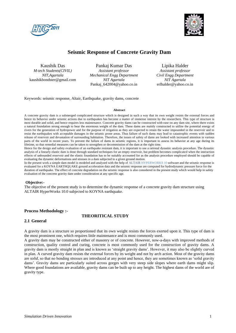
Fig 1.2: Typical section of a concrete gravity dam
2.1.1 FORCES ACTING ON A GRAVITY DAM
Technically a concrete gravity dam derives its stability from the force of gravity of the materials in the section and
hence the name. The gravity dam has sufficient weight so as to withstand the forces and the overturning moment
caused by the water impounded in the reservoir behind it. It transfers the loads to the foundations by cantilever action
and hence good foundations are pre requisite for the gravity dam.
The forces that give stability to the dam include:
1. Weight of the dam
2. Thrust of the tail water
The forces that try to destabilize the dam include:
1. Reservoir water pressure
2. Uplift pressure
3. Forces due to waves in the reservoir
4. Ice pressure
5. Temperature stresses
6. Silt pressure
7. Seismic forces
8. Wind pressure
The forces to be resisted by a gravity dam fall into two categories as given below:
1. Forces, such as weight of the dam and water pressure which are directly calculated from the unit weight of materials
and properties of fluid pressure and
2. Forces such as uplift, earthquake loads, silt pressure and ice pressure which are assumed only on the basis of
assumptions of varying degree of reliability. In fact to evaluate this category of forces, special care has to be taken and
reliance placed on available data, experience and judgment.
Simulation Driven Innovation 3
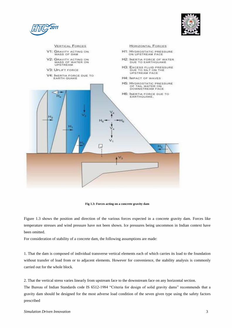
Fig 1.3: Forces acting on a concrete gravity dam
Figure 1.3 shows the position and direction of the various forces expected in a concrete gravity dam. Forces like
temperature stresses and wind pressure have not been shown. Ice pressures being uncommon in Indian context have
been omitted.
For consideration of stability of a concrete dam, the following assumptions are made:
1. That the dam is composed of individual transverse vertical elements each of which carries its load to the foundation
without transfer of load from or to adjacent elements. However for convenience, the stability analysis is commonly
carried out for the whole block.
2. That the vertical stress varies linearly from upstream face to the downstream face on any horizontal section.
The Bureau of Indian Standards code IS 6512-1984 “Criteria for design of solid gravity dams” recommends that a
gravity dam should be designed for the most adverse load condition of the seven given type using the safety factors
prescribed
Simulation Driven Innovation 4
It would be useful to explain in a bit more detail the different loadings and the methods required to calculate them.
These are explained in the following sections.
The significant loadings on a concrete gravity dam include the self-weight or dead load of the dam, the water pressure
from the reservoir, and the uplift pressure from the foundation. There are other loadings, which either occur
intermittently, like earthquake forces, or are smaller in magnitude, like the pressure exerted by the waves generated in
the reservoir that is the upstream of the dam face. These loadings are explained in the following section.
2.1.1.1 DEAD LOAD
The dead load comprises of the weight of the concrete structure of the dam body in addition to pier gates and bridges,
if any over the piers. The density of concrete may be considered as 2400 kg/m³. Since the cross section of a dam
usually would not be simple, the analysis may be carried out by dividing the section into several triangles and
rectangles and the dead load (self weight) of each of these sections (considering unit width or the block width)
computed separately and then added up. For finding out the moment of the dead load (required for calculating stresses),
the moments due to the separate sub–parts may be calculated individually and then summed up.
2.1.1.2. WATER PRESSURE ON DAM
The pressure due to water in the reservoir and that of the tail water acting on vertical planes on the upstream and
downstream side of the dam respectively may be calculated by the law of hydrostatics. Thus, the pressure at any depth
h is given by γh kN/m² acting normal to the surface. When the dam has a sloping upstream face, the water pressure can
be resolved into its horizontal and vertical components, the vertical component being given by the weight of the water
prism on the upstream face and acts vertically downward through the centre of gravity of the water area supported on
the dam face.
In spillway section, when the gates are closed, the water pressure can be worked out in the same manner as for non–
overflow sections except for vertical load of water on the dam itself.
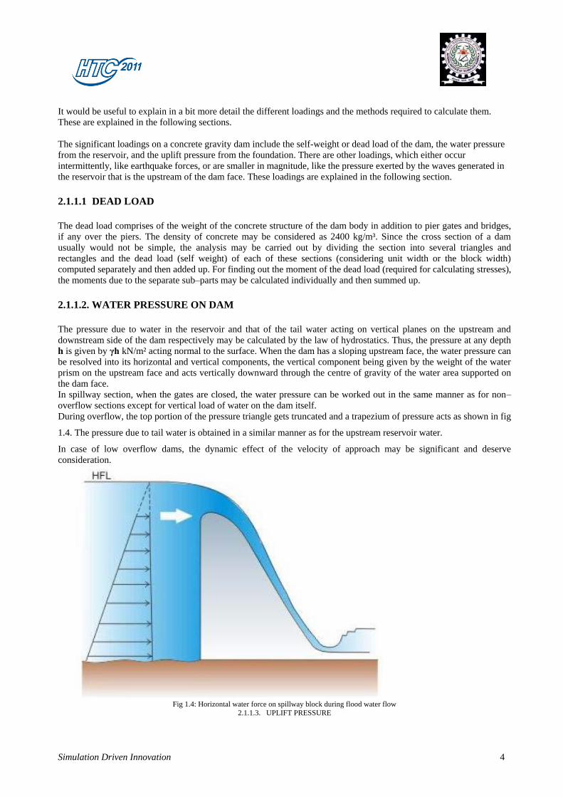
During overflow, the top portion of the pressure triangle gets truncated and a trapezium of pressure acts as shown in fig
1.4. The pressure due to tail water is obtained in a similar manner as for the upstream reservoir water.
In case of low overflow dams, the dynamic effect of the velocity of approach may be significant and deserve
consideration.
Fig 1.4: Horizontal water force on spillway block during flood water flow
2.1.1.3. UPLIFT PRESSURE

Simulation Driven Innovation 5
Uplift forces occur as internal pressure in pores, cracks and seams within the body of the dam, at the contact between
the dam and its foundation and within the foundation. The recent trends for evaluating uplift forces are based on the
phenomenon of seepage through permeable material. Water under pressure enters the pores and fissures of the
foundation material and joints in the dam. The uplift is supposed to act on the whole width plane that is being
considered, either at the base or at any position within the dam. The uplift pressure on the upstream end of the
considered horizontal plane is taken as γhu
where hu
is the depth of water above the plane. On the downstream the
value is γhd
where hd
is again the depth of water above the plane.
Figure 1.5 illustrates the uplift pressure on a concrete gravity dam‟s non overflow section through two planes – one at
the base and the other at the horizontal plane which is above the tail water level. In Figure 1.5, the drainage holes either
in the body of the dam, or within the foundation has not been considered. If the effects of the drainage holes are
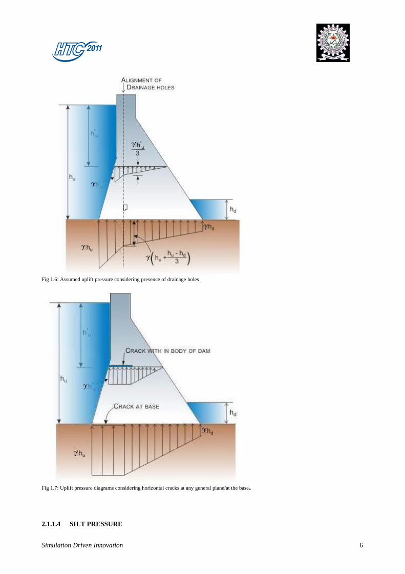
considered, then the uplift pressure diagram gets modified as shown in Figure 1.6. If there is crack at any plane of the
dam, or at the base then the uplift pressure diagram gets further modified as shown in Figure 1.7.
As such, the uplift pressure is assumed to act throughout the base area. Further it is also assumed that they remain
unaffected by earthquakes
Fig 1.5: Uplift pressure at base and at any general plane of the dam body
Simulation Driven Innovation 6
Fig 1.6: Assumed uplift pressure considering presence of drainage holes
Fig 1.7: Uplift pressure diagrams considering horizontal cracks at any general plane/at the base.
2.1.1.4 SILT PRESSURE
Simulation Driven Innovation 7
The weight and the pressure of the submerged silt are to be considered in addition to weight and pressure of water. The
weight of the silt acts vertically on the slope and pressure horizontally, in a similar fashion to the corresponding forces
due to water. It is recommended that the submerged density of silt for calculating horizontal pressure may be taken as
1360 kg/m³. Equivalently, for calculating vertical force, the same may be taken as 1925 kg/m³.
2.1.1.5 EARTHQUAKE PRESSURE
Earthquake or seismic activity is associated with complex oscillating patterns of acceleration and ground motions,
which generate transient dynamic loads due to inertia of the dam and the retained body of water. Horizontal and
vertical accelerations are not equal, the former being of greater intensity.
The earthquake acceleration is usually designated as a fraction of the acceleration due to gravity and is expressed as
α⋅g, where α is the Seismic Coefficient. The seismic coefficient depends on various factors, like the intensity of the
earthquake, the part or zone of the country in which the structure is located, the elasticity of the material of the dam and
its foundation, etc. For the purpose of determining the value of the seismic coefficient which has to be adopted in the
design of a dam, India has been divided into five seismic zones, depending upon the severity of the earthquakes which
may occur in different places. A map showing these zones are given in the Bureau of Indian Standards code IS: 1893-
2002 (Part-1). The methods for determining seismic coefficient are also described in the mentioned code.
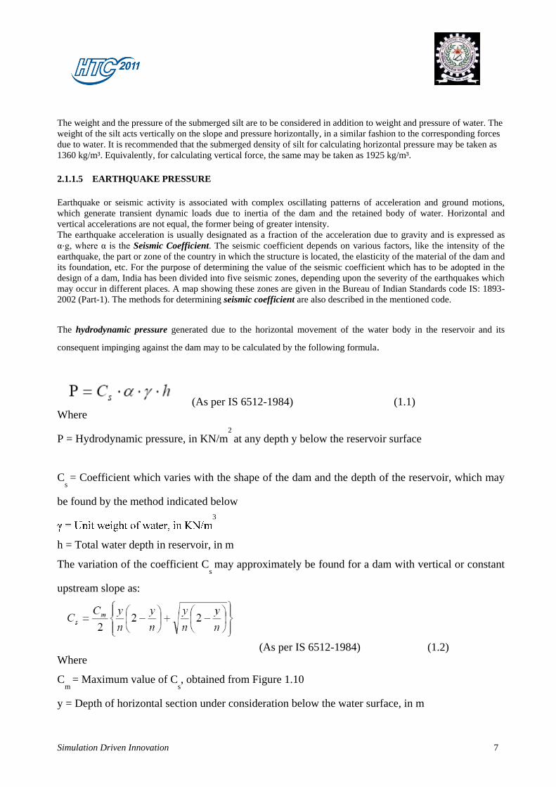
The hydrodynamic pressure generated due to the horizontal movement of the water body in the reservoir and its
consequent impinging against the dam may to be calculated by the following formula.
(As per IS 6512-1984) (1.1)
Where
P = Hydrodynamic pressure, in KN/m2
at any depth y below the reservoir surface
Cs = Coefficient which varies with the shape of the dam and the depth of the reservoir, which may
be found by the method indicated below
3
h = Total water depth in reservoir, in m
The variation of the coefficient Cs may approximately be found for a dam with vertical or constant
upstream slope as:
(As per IS 6512-1984) (1.2)
Where
Cm
= Maximum value of Cs, obtained from Figure 1.10
y = Depth of horizontal section under consideration below the water surface, in m
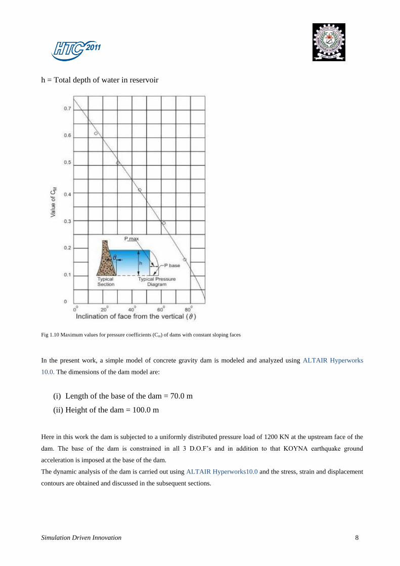
Simulation Driven Innovation 8
h = Total depth of water in reservoir
Fig 1.10 Maximum values for pressure coefficients (Cm) of dams with constant sloping faces
In the present work, a simple model of concrete gravity dam is modeled and analyzed using ALTAIR Hyperworks
10.0. The dimensions of the dam model are:
(i) Length of the base of the dam = 70.0 m
(ii) Height of the dam = 100.0 m
Here in this work the dam is subjected to a uniformly distributed pressure load of 1200 KN at the upstream face of the
dam. The base of the dam is constrained in all 3 D.O.F‟s and in addition to that KOYNA earthquake ground
acceleration is imposed at the base of the dam.
The dynamic analysis of the dam is carried out using ALTAIR Hyperworks10.0 and the stress, strain and displacement
contours are obtained and discussed in the subsequent sections.
Simulation Driven Innovation 9
RESULTS AND DISCUSSIONS
3.1 RESULTS
The dam model is modeled and analysed with ALTAIR Hypermesh 10.0 and the following results are obtained
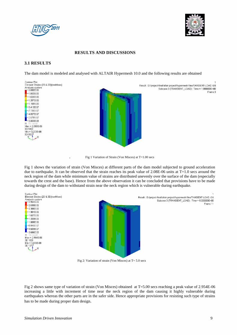
. Fig 1 Variation of Strain (Von Misces) at T=1.00 secs
Fig 1 shows the variation of strain (Von Misces) at different parts of the dam model subjected to ground acceleration
due to earthquake. It can be observed that the strain reaches its peak value of 2.08E-06 units at T=1.0 secs around the
neck region of the dam while minimum value of strains are distributed unevenly over the surface of the dam (especially
towards the crest and the base). Hence from the above observation it can be concluded that provisions have to be made
during design of the dam to withstand strain near the neck region which is vulnerable during earthquake.
Fig 2: Variation of strain (Von Misces) at T= 5.0 secs
Fig 2 shows same type of variation of strain (Von Misces) obtained at T=5.00 secs reaching a peak value of 2.954E-06
increasing a little with increment of time near the neck region of the dam causing it highly vulnerable during
earthquakes whereas the other parts are in the safer side. Hence appropriate provisions for resisting such type of strains
has to be made during proper dam design.
Simulation Driven Innovation 10
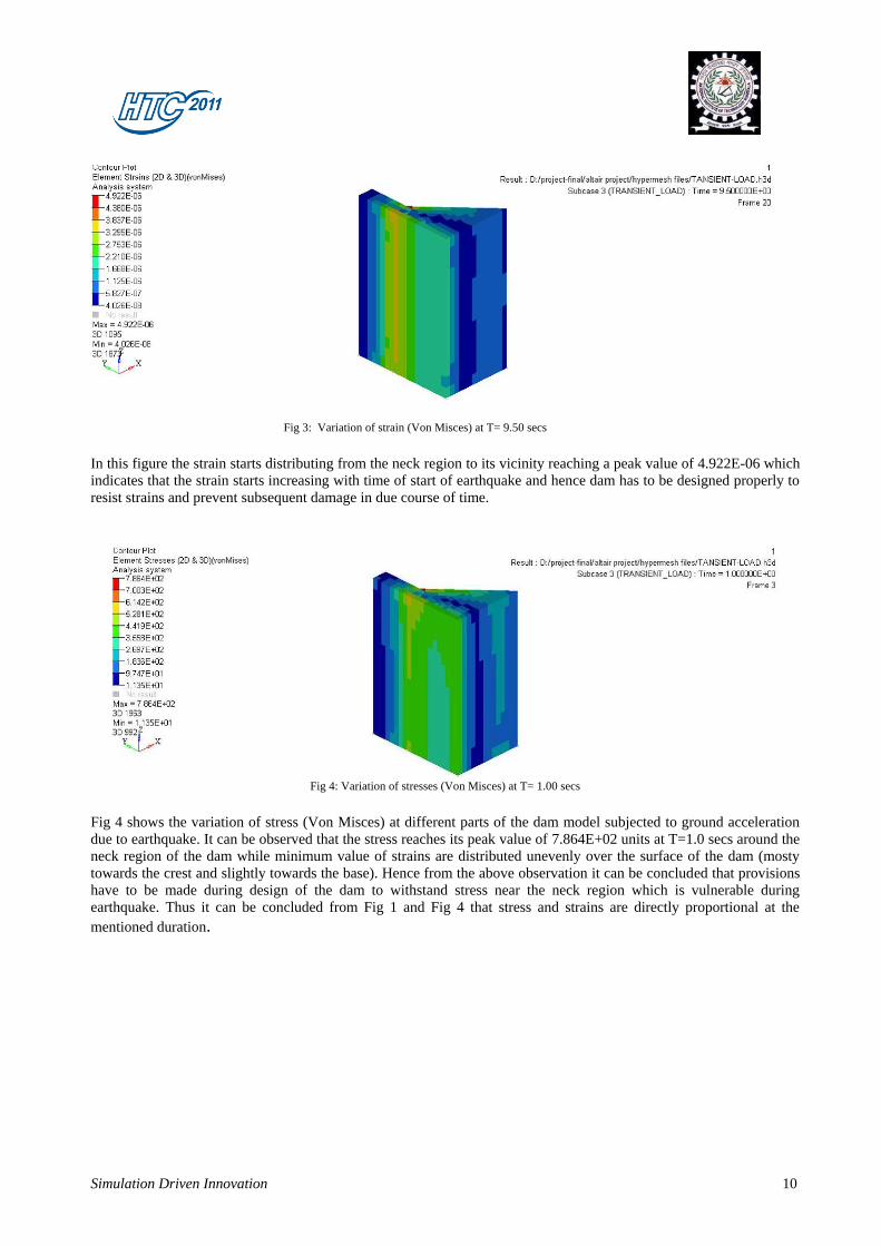
Fig 3: Variation of strain (Von Misces) at T= 9.50 secs
In this figure the strain starts distributing from the neck region to its vicinity reaching a peak value of 4.922E-06 which
indicates that the strain starts increasing with time of start of earthquake and hence dam has to be designed properly to
resist strains and prevent subsequent damage in due course of time.
Fig 4: Variation of stresses (Von Misces) at T= 1.00 secs
Fig 4 shows the variation of stress (Von Misces) at different parts of the dam model subjected to ground acceleration
due to earthquake. It can be observed that the stress reaches its peak value of 7.864E+02 units at T=1.0 secs around the
neck region of the dam while minimum value of strains are distributed unevenly over the surface of the dam (mosty
towards the crest and slightly towards the base). Hence from the above observation it can be concluded that provisions
have to be made during design of the dam to withstand stress near the neck region which is vulnerable during
earthquake. Thus it can be concluded from Fig 1 and Fig 4 that stress and strains are directly proportional at the
mentioned duration.
Simulation Driven Innovation 11
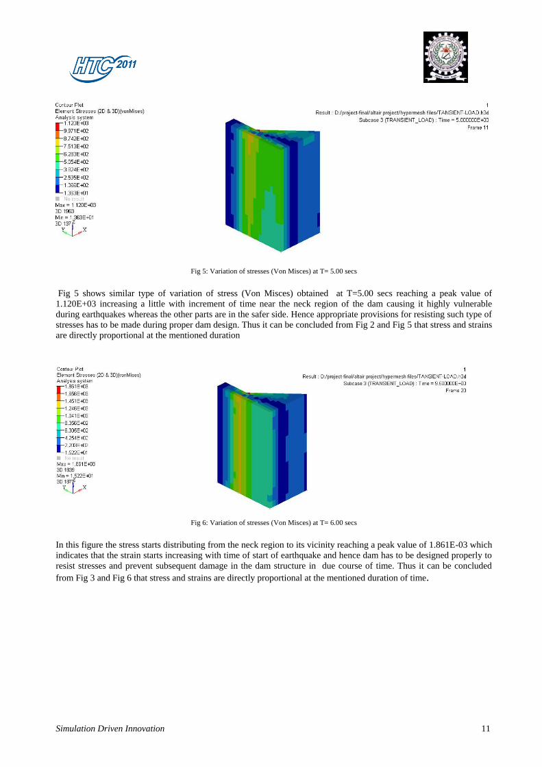
Fig 5: Variation of stresses (Von Misces) at T= 5.00 secs
Fig 5 shows similar type of variation of stress (Von Misces) obtained at T=5.00 secs reaching a peak value of
1.120E+03 increasing a little with increment of time near the neck region of the dam causing it highly vulnerable
during earthquakes whereas the other parts are in the safer side. Hence appropriate provisions for resisting such type of
stresses has to be made during proper dam design. Thus it can be concluded from Fig 2 and Fig 5 that stress and strains
are directly proportional at the mentioned duration
Fig 6: Variation of stresses (Von Misces) at T= 6.00 secs
In this figure the stress starts distributing from the neck region to its vicinity reaching a peak value of 1.861E-03 which
indicates that the strain starts increasing with time of start of earthquake and hence dam has to be designed properly to
resist stresses and prevent subsequent damage in the dam structure in due course of time. Thus it can be concluded
from Fig 3 and Fig 6 that stress and strains are directly proportional at the mentioned duration of time.
Simulation Driven Innovation 12
Benefits And Summary
4.1 BENEFITS
Since the concrete gravity dam is a very big and complicated structure it consumes a lot of time for the analysis and
design of such structure, if done manually. Also the experimental set up required for modeling and analysis of such
model is very expensive and the results obtained might be erroneous if proper care is not taken while working with the
experimental model setup.
Hence the current trend of the researchers is towards development of numerical softwares which can be used for
rational dynamic analysis of such dams with much accurate results and error minimization.
Hence it is very convenient and cost effective to model and analyse the dam model using ALTAIR Hypermesh 10.0
which produces almost accurate results of various responses.
4.2 SUMMARY
Based on the present findings following conclusions can be drawn.
(i) Crest displacement is found to maximum at the peak of the dam and increases with time period of earthquake,
hence proper measures should be taken while designing of dam.
(ii) Stresses and strains starts increasing and distributing from the neck region to the other parts of dam with
increase of time period of earthquake, hence proper steps should be taken for prevention of damage or
failure in dams due to excessive accumulation of stresses and strains.
SCOPE FOR FUTURE WORK OF THE PROJECT
5.1 Future Scope In addition to the present analysis done using ALTAIR Hypermesh 10.0 there are certain other
developmental aspects that may be considered for further research:
(i) The degradation of concrete strength with age may induce formation of cracks. A
study of crack formation and propagation may be carried out to predict the nonlinear behavior of the dam.
Hence inclusion of the material non-linearity in both isotropic and anisotropic materials may be the
subject of further research.
(ii) The present model does not account for thermal stresses due to hydration concrete which may affect ageing of
the dam.
(iii) The present problem may be extended to 3-dimensional form with the proper
inclusion of radiation boundary condition for the unbounded reservoir.
(iv) The present problem may be extended to study the effect of foundation flexibility
of dam considering soil-structure interaction to obtain more precise behavior of the coupled system. More
accurate behavior may be obtained if coupled effect of
the foundation-dam-reservoir interaction is considered.
Simulation Driven Innovation 13
ACKNOWLEDGEMENT
I would hereby like to express my sincere gratitude to Mr. Abhijit Kulkarni,Designtech Systems Ltd allowing
me to work under his excellent supervision and guidance for which I am highly obliged.
The valuable time and effort, and the useful suggestions and advice they had rendered has helped me to keep my
self belief and morale high and strong towards completion of this paper publication .
I would also like express my heartiest thanks to Dr. Damodar Maity, Proff, Civil Engg Dept, IIT Kharagpur and
Dr. Richi Prasad Sharma, Proff, Civil Engg Dept, NIT Agartala for their useful suggestions and encouragement
towards successful completion of this project and carrying it forward in future.
REFERRENCES
Bazant, Z.P. (1994) “Creep and thermal effects in concrete structures: a conceptus of some
new developments”, Computational modelling of Concrete Structures, International
Conf. EURO-C, H. Mang, N. Bicanic and R. de Borst. eds., Pineridge Press, Swansea,
Wales, 461-480.
Bazant, Z.P., Hauggaard, A.B., Baweja, S. and Ulm, F.J. (1997) “Micro prestress solidification
theory for concrete creep. I: Aging and drying effects”, Journal of
Engineering Mechanics, ASCE, 123(11), 1188-1194.
Bazant, Z.P. and Xiang, Y. (1997) “Crack growth and lifetime of concrete under long time
loading”, Journal of Engineering Mechanics, ASCE, 123(4), 350-
Bougacha, S. and Tassoulas, J. L. (1991a) “Effect of sediment material on the response of
concrete gravity dams”, Earthquake Engineering and Structural Dynamics, 20(9), 849-
858.
Bougacha, S. and Tassoulas, J.L. (1991b) “Seismic response of gravity dams. I. Modelling
of sediments”, Journal of Engineering Mechanics, ASCE, 117(8), 1826-1838
Bougacha, S. and Tassoulas, J.L. (1991c) “Seismic response of gravity dams. II. Effects of
sediments”, Journal of Engineering Mechanics, ASCE, 117(8), 1839-1850
Byfors, J. (1980) “Plain concrete at early ages”, Research Report F3:80, Swedish Cement
and Concrete Research Institute, Stockholm, Sweden
Cervera. M., Oliver, J. and Faria, R. (1995) “Seismic evaluation of concrete dams via
continuum damage models”, Earthquake Engineering and Structural Dynamics, 24(9),
1225-1245.
Cervera, M., Oliver, J. and Prato, T. (1999a) “Thermo-Chemo-Mechanical Model for
Concrete. I: Hydration and Aging”, Journal of Engineering Mechanics, ASCE, 125,
1018 -1027.
Cervera, M., Oliver, J. and Prato, T. (1999b) “Thermo-Chemo-Mechanical Model for
Concrete. II: Damage and Creep”, Journal of Engineering Mechanics, ASCE, 125,
1028- 1039.
Cervera, M., Oliver, J. and Prato, T. (2000a) “Simulation of construction of RCC dams I:
Temperature and aging”, Journal of Structural Engineering, ASCE, 126(9), 1053-1061.
Chakrabarti, P. and Chopra, A.K. (1973) “Earthquake analysis of gravity dams including
hydrodynamic interaction”, Earthquake Engineering and Structural Dynamics, 2, 143-
160.
Chandrashaker, R. and Humar, J.L. (1993) “Fluid-foundation interaction in the seismic
response of gravity dams”, Earthquake Engineering and Structural Dynamics, 22,
1067-1084.
Chavez, J.W. and Fenves, G.L. (1995) “Earthquake analysis of concrete gravity dams