Embed Size (px)
Citation preview
2nd International Nuclear Power Plants: Structures, Risk & Decommissioning - NUPP2018
London, UK, June 11-12, 2018
SEISMIC SOIL-STRUCTURE INTERACTION (SSI) EFFECTS FOR DEEPLY
EMBEDDED NUCLEAR ISLANDS SURROUNDED BY SOFT BACKFILLS
D. M. Ghiocel, Ghiocel Predictive Technologies, Inc., New York, USA
ABSTRACT This short paper addresses a technical subject topic of a special interest for seismic analysis of the deeply embedded
nuclear islands surrounded by limited-size backfill soils that are significantly softer than the in-situ soil deposit. On this
technical subject there is a lack of information in the published literature. To capture the backfill dynamic effects, the
backfill soil must be included in the SSI FE model as a near-field soil. It should be noted that backfill dynamic effects
impacts severely on the seismic SSI responses, especially on ISRS, both in the low and high frequency ranges depending
on the backfill soil properties and sizes, and the seismic input frequency content. Motion incoherency and nonlinear
backfill soil behaviour may also affect the backfill dynamic behaviour.
1. INTRODUCTION
If the limited-size surrounding backfill soil is much
softer comparing with in-situ soil, the scattered wave
energy is largely trapped in the backfill. The interface
between the backfill and the much stiffer in-situ soil
acts as a real reflective boundary in the physical space.
For certain frequency intervals, the backfill motion can
be highly amplified in comparison with the free-field
soil motion. The computed in-structure response
spectra (ISRS) could be significantly affected. The
ISRS spectral peaks could be 50-100% larger, or even
larger, due to the backfill soil dynamic behaviour.
Seismic motion incoherency and nonlinear backfill soil
behaviour are additional influential factors that affect
the backfill dynamic behaviour.
2. EXCAVATED SOIL MODELING ISSUES
If the backfill soil is different than the in-situ soil, then,
the surrounding backfill soil should be included in the
SASSI FE model as a near-field soil. This increases the
size of the entire SASSI FE model, that includes the
structure FE model, the excavated soil FE model and
the excavated soil FE model.
If the surrounding backfill soil is much softer than the
in-situ soil layering, the required FE mesh should be
much more refined for the backfill soil than for the in-
situ soil layering. The refined mesh of the soft backfill
soil is required for transmitting accurately the high-
frequency wave components through the soft backfill
material. However, if the refined soft backfill FE mesh
is also used for the in-situ soil layering, then, the
number of the interaction nodes explodes, and the
computational SSI analysis effort increases largely by
at least a magnitude order, if not much more.
For the soft backfill soil models, using a coarser
regular FE mesh for the excavated soil model is highly
beneficial not only for speeding up the SSI analysis by
reducing the number of interaction nodes, but also for
improving the accuracy of the SSI analysis. It should
be noted that in a recent published BNL report
authored by the USNRC BNL expert consultants [1], in
the conclusion section it is stated that an important SSI
modelling aspect to be addressed is “the need for
regular excavated soil mesh for any reasonable FE
structural model”. The BNL report refers to typical
situations when the bottom FE mesh of the structural
model has an irregular mesh, due to the constraints
from the complex geometries of the reactor buildings.
Using the bottom irregular structure FE mesh to build
the excavated soil FE mesh is not the most accurate
SSI modelling practice.
To be able to define the excavated soil FE mesh as a
regular mesh, transition mesh zones may be required to
connect the structure FE mesh with the excavated soil
FE mesh. This adds a new SSI modelling complexity
for highly irregular foundation meshes, but the benefits
obtained for the SSI analysis computational speed and
its accuracy are highly rewarding.
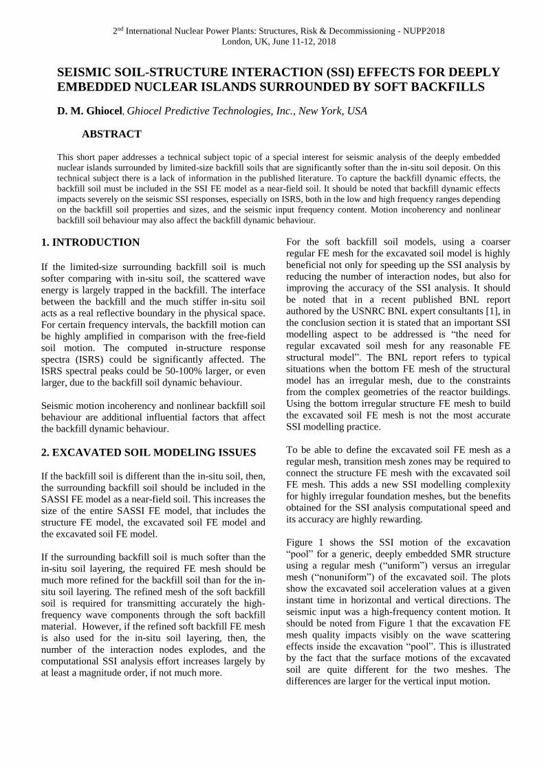
Figure 1 shows the SSI motion of the excavation
“pool” for a generic, deeply embedded SMR structure
using a regular mesh (“uniform”) versus an irregular
mesh (“nonuniform”) of the excavated soil. The plots
show the excavated soil acceleration values at a given
instant time in horizontal and vertical directions. The
seismic input was a high-frequency content motion. It
should be noted from Figure 1 that the excavation FE
mesh quality impacts visibly on the wave scattering
effects inside the excavation “pool”. This is illustrated
by the fact that the surface motions of the excavated
soil are quite different for the two meshes. The
differences are larger for the vertical input motion.
2nd International Nuclear Power Plants: Structures, Risk & Decommissioning - NUPP2018
London, UK, June 11-12, 2018
2
a) Horizontal Seismic Input
b) Vertical Seismic Input
Figure 1 Excavated Soil Acceleration Profiles for
Horizontal and Vertical Directions
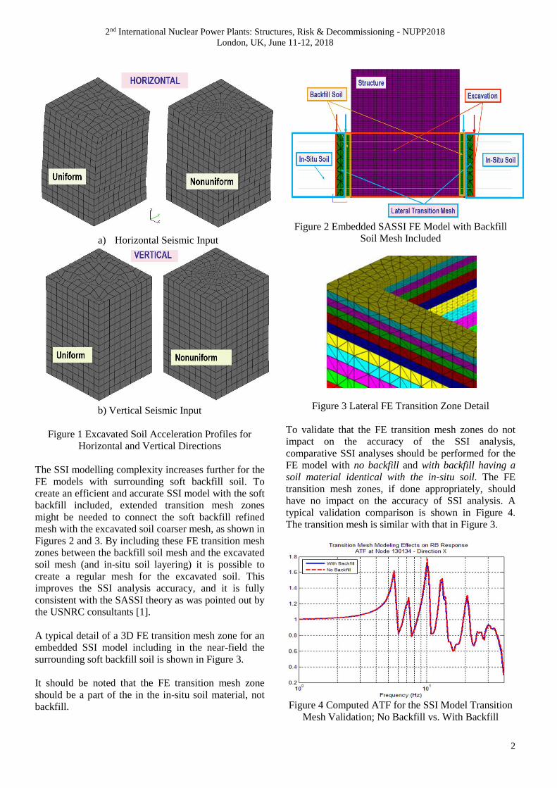
The SSI modelling complexity increases further for the
FE models with surrounding soft backfill soil. To
create an efficient and accurate SSI model with the soft
backfill included, extended transition mesh zones
might be needed to connect the soft backfill refined
mesh with the excavated soil coarser mesh, as shown in
Figures 2 and 3. By including these FE transition mesh
zones between the backfill soil mesh and the excavated
soil mesh (and in-situ soil layering) it is possible to
create a regular mesh for the excavated soil. This
improves the SSI analysis accuracy, and it is fully
consistent with the SASSI theory as was pointed out by
the USNRC consultants [1].
A typical detail of a 3D FE transition mesh zone for an
embedded SSI model including in the near-field the
surrounding soft backfill soil is shown in Figure 3.
It should be noted that the FE transition mesh zone
should be a part of the in the in-situ soil material, not
backfill.
Figure 2 Embedded SASSI FE Model with Backfill
Soil Mesh Included
Figure 3 Lateral FE Transition Zone Detail
To validate that the FE transition mesh zones do not
impact on the accuracy of the SSI analysis,
comparative SSI analyses should be performed for the
FE model with no backfill and with backfill having a
soil material identical with the in-situ soil. The FE
transition mesh zones, if done appropriately, should
have no impact on the accuracy of SSI analysis. A
typical validation comparison is shown in Figure 4.
The transition mesh is similar with that in Figure 3.
Figure 4 Computed ATF for the SSI Model Transition
Mesh Validation; No Backfill vs. With Backfill
2nd International Nuclear Power Plants: Structures, Risk & Decommissioning - NUPP2018
London, UK, June 11-12, 2018
Figure 4 compares the acceleration transfer function
(ATF) amplitude computed for a deeply embedded RB
model with and without the backfill mesh included.
The backfill soil and the in-situ soil properties were
assumed to be identical. The computed ATF curves are
overlapped, as expected for validation.
3. SOFT BACKFILL SOIL DYNAMIC EFFECTS
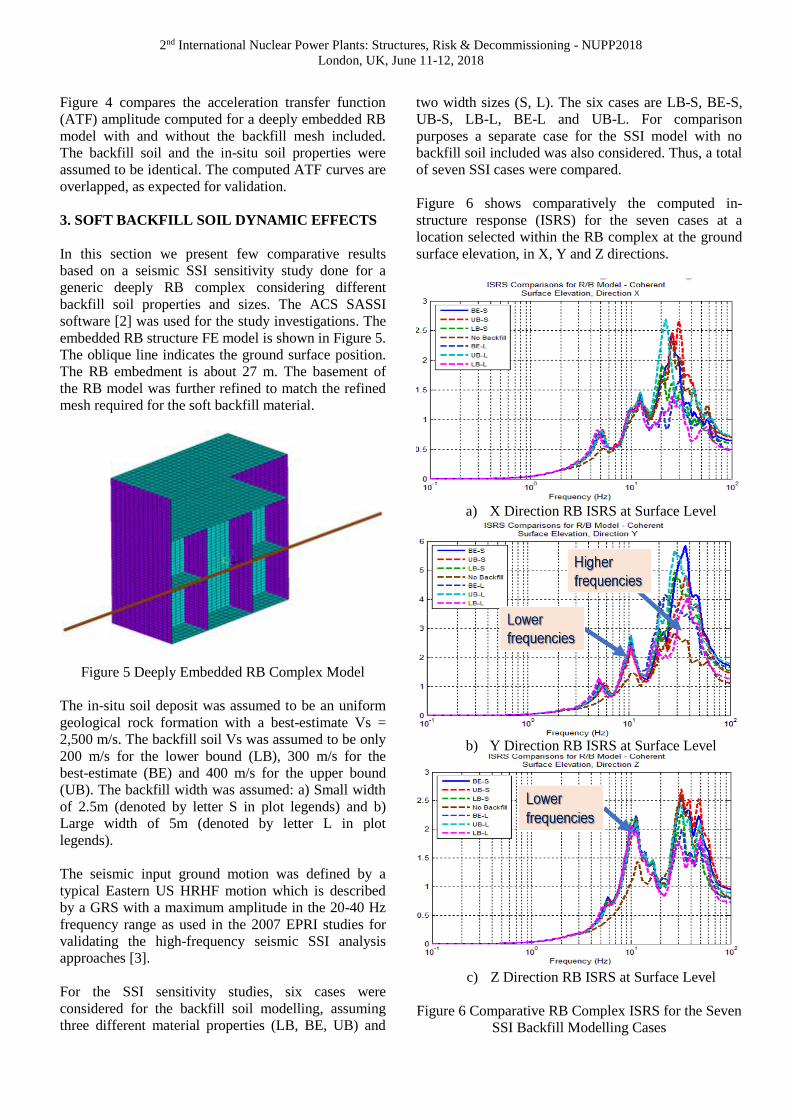
In this section we present few comparative results
based on a seismic SSI sensitivity study done for a
generic deeply RB complex considering different
backfill soil properties and sizes. The ACS SASSI
software [2] was used for the study investigations. The
embedded RB structure FE model is shown in Figure 5.
The oblique line indicates the ground surface position.
The RB embedment is about 27 m. The basement of
the RB model was further refined to match the refined
mesh required for the soft backfill material.
Figure 5 Deeply Embedded RB Complex Model
The in-situ soil deposit was assumed to be an uniform
geological rock formation with a best-estimate Vs =
2,500 m/s. The backfill soil Vs was assumed to be only
200 m/s for the lower bound (LB), 300 m/s for the
best-estimate (BE) and 400 m/s for the upper bound
(UB). The backfill width was assumed: a) Small width
of 2.5m (denoted by letter S in plot legends) and b)
Large width of 5m (denoted by letter L in plot
legends).
The seismic input ground motion was defined by a
typical Eastern US HRHF motion which is described
by a GRS with a maximum amplitude in the 20-40 Hz
frequency range as used in the 2007 EPRI studies for
validating the high-frequency seismic SSI analysis
approaches [3].
For the SSI sensitivity studies, six cases were
considered for the backfill soil modelling, assuming
three different material properties (LB, BE, UB) and
two width sizes (S, L). The six cases are LB-S, BE-S,
UB-S, LB-L, BE-L and UB-L. For comparison
purposes a separate case for the SSI model with no
backfill soil included was also considered. Thus, a total
of seven SSI cases were compared.
Figure 6 shows comparatively the computed in-
structure response (ISRS) for the seven cases at a
location selected within the RB complex at the ground
surface elevation, in X, Y and Z directions.
a) X Direction RB ISRS at Surface Level
b) Y Direction RB ISRS at Surface Level
c) Z Direction RB ISRS at Surface Level
Figure 6 Comparative RB Complex ISRS for the Seven
SSI Backfill Modelling Cases
2nd International Nuclear Power Plants: Structures, Risk & Decommissioning - NUPP2018
London, UK, June 11-12, 2018
4
The sensitivity study results, as shown in Figure 6,
indicated that the backfill soil dynamic effects could
largely affect the computed ISRS in both low- and
high-frequency ranges. ISRS amplitude increases of up
to 100% are shown in Figure 6. Similar results were
obtained for many other locations within RB complex.
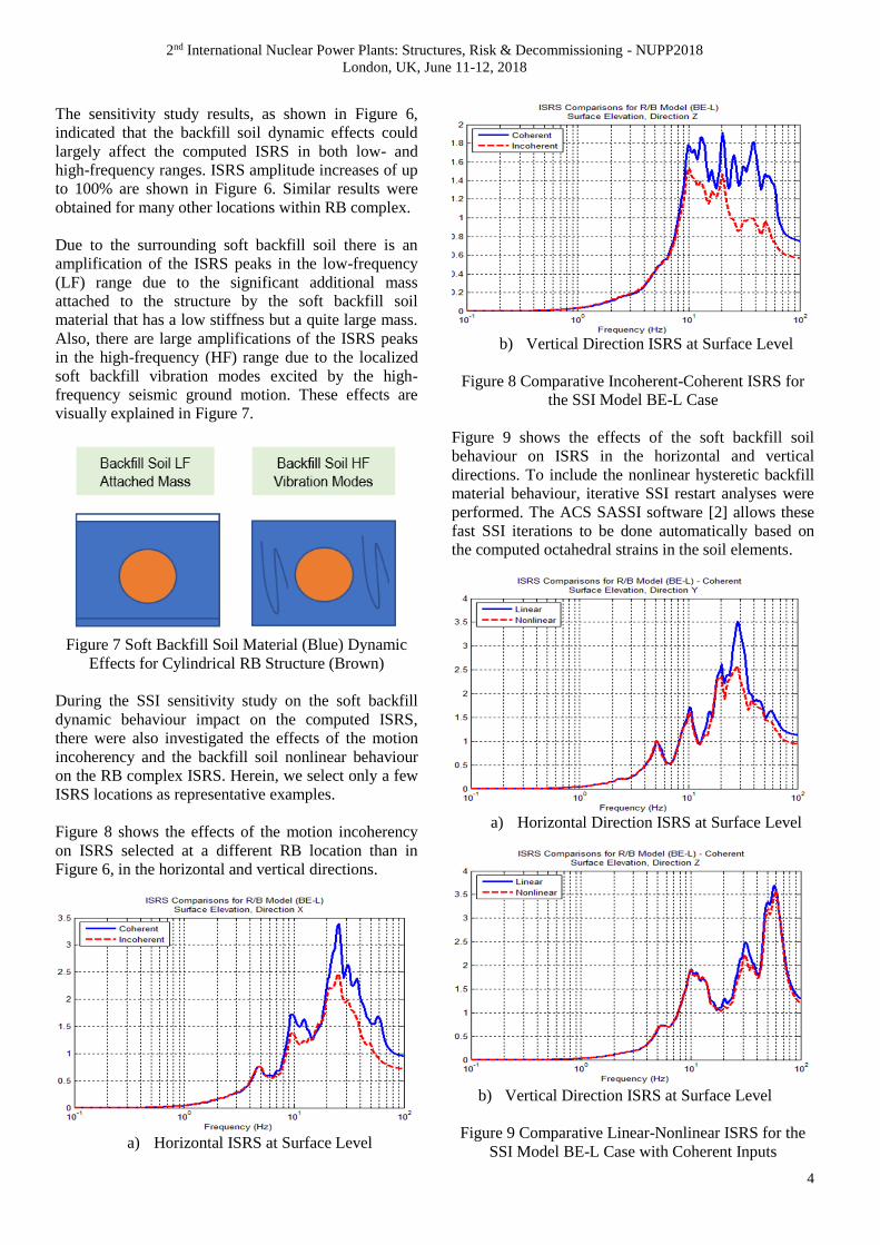
Due to the surrounding soft backfill soil there is an
amplification of the ISRS peaks in the low-frequency
(LF) range due to the significant additional mass
attached to the structure by the soft backfill soil
material that has a low stiffness but a quite large mass.
Also, there are large amplifications of the ISRS peaks
in the high-frequency (HF) range due to the localized
soft backfill vibration modes excited by the high-
frequency seismic ground motion. These effects are
visually explained in Figure 7.
Figure 7 Soft Backfill Soil Material (Blue) Dynamic
Effects for Cylindrical RB Structure (Brown)
During the SSI sensitivity study on the soft backfill
dynamic behaviour impact on the computed ISRS,
there were also investigated the effects of the motion
incoherency and the backfill soil nonlinear behaviour
on the RB complex ISRS. Herein, we select only a few
ISRS locations as representative examples.
Figure 8 shows the effects of the motion incoherency
on ISRS selected at a different RB location than in
Figure 6, in the horizontal and vertical directions.
a) Horizontal ISRS at Surface Level
b) Vertical Direction ISRS at Surface Level
Figure 8 Comparative Incoherent-Coherent ISRS for
the SSI Model BE-L Case
Figure 9 shows the effects of the soft backfill soil
behaviour on ISRS in the horizontal and vertical
directions. To include the nonlinear hysteretic backfill
material behaviour, iterative SSI restart analyses were
performed. The ACS SASSI software [2] allows these
fast SSI iterations to be done automatically based on
the computed octahedral strains in the soil elements.
a) Horizontal Direction ISRS at Surface Level
b) Vertical Direction ISRS at Surface Level
Figure 9 Comparative Linear-Nonlinear ISRS for the
SSI Model BE-L Case with Coherent Inputs
2nd International Nuclear Power Plants: Structures, Risk & Decommissioning - NUPP2018
London, UK, June 11-12, 2018
Figures 8 and 9 indicate that the effects of both the
motion incoherency and the soft backfill soil nonlinear
hysteretic behaviour on the RB complex ISRS are quite
significant. Both effects reduce the high-frequency
ISRS peaks in the horizontal direction, but only
incoherency reduces the ISRS peaks in the vertical
direction. As shown in Figure 9b, the backfill nonlinear
behaviour has minimal effects on the vertical ISRS.
4. CONCLUSIONS
The paper investigates the effects of the soft backfill
soil dynamic behaviour for a generic deeply embedded
RB building founded on a rock site subjected to a high-
frequency seismic ground motion. These backfill soil
effects are significant on the ISRS for both the low-
and high-frequency ranges.
The backfill soil dynamic effects on ISRS depend on
the backfill properties and sizes as shown herein.
The backfill soil effects on ISRS are also affected by
other influential factors, as motion incoherency and
nonlinear backfill material nonlinear behaviour as
illustrated by this paper results.
The in-situ soil stiffness relative to the backfill soil
stiffness is a potential influential factor that will need
to be investigated in future.
5. REFERENCES
1. Nie, J., Braverman, J., and Costantino, M. (2013).
“Seismic Soil-Structure Interaction Analyses of a
Deeply Embedded Model Reactor – SASSI Analyses”,
U.S. Department of Energy, Brookhaven National
Laboratory, BNL 102434-2013, New York
2. Ghiocel Predictive Technologies, Inc. (2018). “ACS
SASSI - An Advanced Computational Software for 3D
Dynamic Analyses Including SSI Effects”, ACS SASSI
Version 3 User Manuals, February 28
3. Short, S.A., G.S. Hardy, K.L. Merz, and J.J. Johnson
(2007). “Validation of CLASSI and SASSI to Treat
Seismic Wave Incoherence in SSI Analysis of Nuclear
Power Plant Structures”, Electric Power Research
Institute, Palo Alto, CA and US Department of Energy,
Germantown, MD, Report No. TR-1015111,
November