Embed Size (px)
Citation preview
Schweitzer Engineering Laboratories, Inc. SEL-451 Data Sheet
SEL-451 Protection, Automation, and Control System
Major Features and Benefits
The SEL-451 Protection, Automation, and ControlSystem combines directional overcurrent protection withcomplete control for a two-breaker bay.
➤ Protection. Use multiple instantaneous and time-overcurrent elements with SELOGIC® controlequations to customize distribution protection.Best Choice Ground Directional Element™ logicoptimizes directional element performance andeliminates the need for many directional settings.Protect two breakers with one relay.
➤ Automation. Take advantage of enhanced automa-tion features that include 32 programmable ele-ments for local control, remote control, protectionlatching, and automation latching. Local meteringon the large format front-panel Liquid Crystal Dis-play (LCD) eliminates the need for separate panelmeters. Use serial and Ethernet links to efficientlytransmit key information, including metering data,protection element and control I/O status, IEEEC37.188 Synchrophasors, IEC 61850 GOOSEmessages, Sequential Events Recorder (SER)reports, breaker monitor, relay summary eventreports, and time synchronization. Use expandedSELOGIC control equations with math and compar-ison functions in control applications. High-isola-tion inputs have settable assertion levels to easilycombine inputs from different systems. Incorporateup to 1000 lines of automation logic to speed andimprove control actions.
➤ High-Accuracy Time-Stamping. Time-tag binaryCOMTRADE event reports with real-time accu-racy of better than 10 µs. View system state infor-mation to an accuracy of better than 1/4 of anelectrical degree.
➤ Synchrophasors. Make informed load dispatchdecisions based on actual real-time phasor mea-surements from across your power system. Usesynchrophasors to determine actual stability mar-gins with standard spreadsheet, graphics program,or data management system.
➤ High-impedance Fault Detection. The optionalhigh-impedance fault (HIF) detection elementoperates for small current ground faults typicallycaused by downed conductors on ground surfacessuch as earth, concrete or other poorly conductivematerials. HIF event data are made available instandard COMTRADE format.
➤ Digital Relay-to-Relay Communications. UseEnhanced MIRRORED BITS® communications tomonitor internal element conditions between relayswithin a station, or between stations, using SELfiber-optic transceivers. Send digital, analog, andvirtual terminal data over the same MIRROREDBITS channel.
➤ Ethernet Access. Access all relay functions withthe optional Ethernet card. Interconnect with auto-mation systems using IEC 61850 or DNP3 proto-col directly. Optionally connect to DNP3 networksthrough an SEL-2032 Communications Processor.Use file transfer protocol (FTP) for high-speed
SEL-451 Data Sheet Schweitzer Engineering Laboratories, Inc.
2
data collection. Connect to substation or corporateLANs to transmit synchrophasors in the IEEEC37.118-2005 format using TCP or UDP internetprotocols.
➤ Dual CT Input. Apply with ring bus, breaker-and-a-half, or other two-breaker schemes. Combinecurrents within the relay from two sets of CTs forprotection functions, but keep them separatelyavailable for monitoring and station integrationapplications.
➤ Monitoring. Schedule breaker maintenance whenaccumulated breaker duty (independently moni-tored for each pole of two circuit breakers) indi-cates possible excess contact wear. Electrical andmechanical operating times are recorded for boththe last operation and the average of operationssince function reset. Alarm contacts provide notifi-cation of substation battery voltage problems (twoindependent battery monitors) even if voltage islow only during trip or close operations.
➤ Reclosing. Incorporate programmable reclosing ofone or two breakers into an integrated substationcontrol system. Synchronism and voltage checksfrom multiple sources provide complete bay con-trol.
➤ Breaker Failure. Use high-speed (less than onecycle) open-pole detection logic to reduce coordi-nation times for critical breaker failure applica-tions. Apply the SEL-451 to supply breaker failureprotection for one or two breakers. Logic forbreaker failure retrip and initiation of transfer trip-ping is included.
➤ Fault Locator. Efficiently dispatch line crews toquickly isolate line problems and restore servicefaster.
➤ Oscillography and Event Reporting. Recordvoltages, currents, and internal logic points at up to8 kHz sampling rate. Off line phasor and harmonicanalysis features allow investigation of relay andsystem performance.
➤ Rules-Based Settings Editor. Communicate withand set the relay using an ASCII terminal, or usethe PC-based ACSELERATOR® QuickSet™SEL-5030 Software to configure the SEL-451 andanalyze fault records with relay element response.
➤ Sequential Events Recorder (SER). Record thelast 1000 entries, including setting changes, power-ups, and selectable logic elements.
➤ Thermal Overload Modeling. Use the SEL-451with the SEL-2600A RTD Module for dynamicoverload protection using SELOGIC control equa-tions.
➤ Comprehensive Metering. Improve feeder load-ing by using built-in, high-accuracy metering func-tions. Use watt and VAR measurements tooptimize feeder operation. Minimize equipmentneeds with full metering capabilities, including:rms, maximum/minimum, demand/peak, energy,and instantaneous values.
➤ Auxiliary Trip/Close Pushbuttons. Theseoptional pushbuttons are electrically isolated fromthe rest of the relay. They function independentlyfrom the relay and do not need relay power.
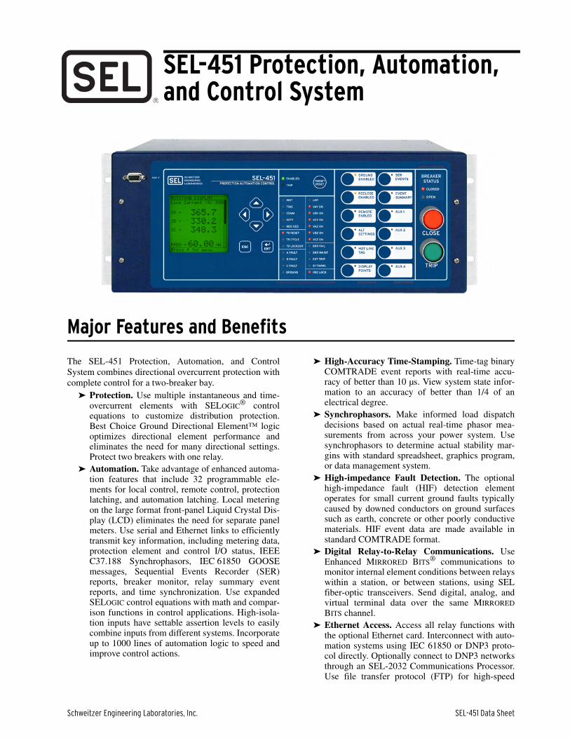
Figure 1 Functional Overview
• Password Separation of
Protection and Automation
• Expanded SELOGIC®
Control Equations
• Event Reports and Oscillography
• Sequential Events Recorder
• Dual Breaker Condition Monitor
• Station Battery Monitor
• DNP3 and/or IEC 61850*
• High-Accuracy Metering
• MIRRORED BITS® Communications
• Remote and
Local Control Switches
• Advanced Local Display
• Fault Locator
• Load Encroachment Supervision
Bus
Bus
Line
SEL-451
50BF
67
50 51
79
25
3
1
3
1
3
DirectionalOvercurrent
Dual CircuitBreaker Failure
SynchronismCheck
Three-PoleReclosing
Time-Overcurrent
InstantaneousOvercurrent
52
52
* Optional Feature
SEL-2600A
Schweitzer Engineering Laboratories, Inc. SEL-451 Data Sheet
3
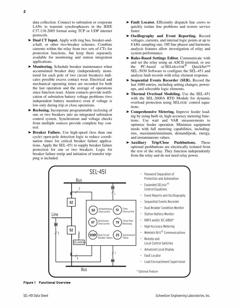
Protection FeaturesDirectional Elements Increase Sensitivity and SecurityThe SEL-451 provides multiple directional elements tooptimize security and sensitivity. Use ground andnegative-sequence directional overcurrent elements todetect high-resistance faults when usingcommunications-assisted tripping schemes.
The SEL-451 includes a number of directional elementsfor supervision of overcurrent elements. The negative-sequence directional element uses the same patentedprinciple proven in our SEL-351 Relay. This directionalelement can be applied in virtually any application,regardless of the amount of negative-sequence voltageavailable at the relay location.
Ground overcurrent elements are directionally controlledby three directional elements working together:
➤ Negative-sequence voltage-polarized directionalelement
➤ Zero-sequence voltage-polarized directional element➤ Zero-sequence current-polarized directional element
Our patented Best Choice Ground Directional Element™
selects the best ground directional element for the systemconditions and simplifies directional element settings.(You can override this automatic setting feature forspecial applications.)
Communications-Assisted Tripping SchemesUse communications to improve tripping time for bettercustomer service. The SEL-451 is the ideal relay for usein pilot-based tripping schemes. Use EnhancedMIRRORED BITS communications with SEL fiber-optictransceivers for 3–6 ms relay-to-relay transmission time.Among the schemes supported are:
➤ Permissive Overreaching Transfer Tripping(POTT)
➤ Directional Comparison Unblocking (DCUB)➤ Directional Comparison Blocking (DCB)
Use the SELOGIC control equation TRCOMM toprogram specific elements, combinations of elements,inputs, etc., to perform communications scheme trippingand other scheme functions. The logic readilyaccommodates the following conditions:
➤ Current reversals➤ Breaker open at one terminal➤ Weak-infeed conditions at one terminal➤ Switch-onto-fault conditions
Time-overcurrent protection provides reliable backupoperation should the channel be lost.
Overcurrent ElementsThe SEL-451 includes four phase, four negative-sequence, and four ground instantaneous overcurrentelements. The SEL-451 also includes six selectableoperating quantity inverse-time overcurrent elements.You can select the operating quantities from thefollowing:
|IA|, |IB|, |IC|, MAX(|IA|, |IB|, |IC|), |I1|, |3I2|, |IG|
where |IA|, |IB|, |IC| can be fundamental or rms quantitiesfrom either circuit breaker, or combined currents.
The time-overcurrent curves (listed in Table 1) have tworeset characteristic choices for each time-overcurrentelement. One choice resets the elements if current dropsbelow pickup for one cycle. The other choice emulatesthe reset characteristic of an electromechanical inductiondisc relay.
Breaker Failure ProtectionIncorporated into the SEL-451 is a full-function breakerfailure system. Current can be individually monitored intwo breakers. High-speed open-pole detection logicallows you to set the pickup current below minimumload, for sensitivity without sacrificing high-speeddropout. Even in cases with delayed current zero in thesecondary of the CT caused by trapped flux, high-speeddetection of circuit breaker opening is achieved. Thisfeature is essential if breaker failure is initiated on allcircuit breaker trips. A reset of less than one cyclereduces coordination times, improving stability.
Thermal Overload ProtectionThe SEL-451 supports receipt of Fast Messages from theSEL-2600A RTD Module. Magnitude information fromthe SEL-2600A is placed in pre-defined analog valuesand status information is stored in pre-definedRelay Word bits. For more information, see SEL
Table 1 Time-Overcurrent Curves
US IEC
Moderately Inverse Standard Inverse
Inverse Very Inverse
Very Inverse Extremely Inverse
Extremely Inverse Long-Time Inverse
Short-Time Inverse Short-Time Inverse
SEL-451 Data Sheet Schweitzer Engineering Laboratories, Inc.
4
Application Guide AG2003-06, Implementation of theSEL-49 Relay Line Thermal Protection Using the SEL-421 Relay SELOGIC Equations.
Loss-of-Potential (LOP) Logic Supervises Directional ElementsThe SEL-451 includes logic to detect a loss-of-potential(LOP) caused by failures such as blown fuses, which cancause an incorrect operation in directional elements.Simple settings configure the LOP logic to either blockor force forward ground and phase directional elementsunder these conditions. The logic checks for a suddenchange in positive-sequence voltage without acorresponding change in positive- or zero-sequencecurrent. Tests and field experience show that thisprinciple is very secure and is faster than the trippingelements.
High-Impedance Fault DetectionHigh-impedance faults are short-circuit faults with faultcurrents smaller than what a traditional overcurrentprotective relay can detect. The SEL-451 includes logicused to detect HIF signatures without being affected byloads and other system operation conditions. A runningaverage provides a stable pre-fault reference and adaptivetuning learns and tunes out feeder ambient noiseconditions. Decision logic differentiates an HIFcondition from other system conditions such asswitching operations and noisy loads. Up to 40 minutesof high-impedance fault activity is stored in high-resolution COMTRADE format and a summary of HIFactivity is available using ASCII commands.
Six Independent Settings Groups Increase Operation FlexibilityThe relay stores six settings groups. Select the activesettings group by control input, command, or otherprogrammable conditions. Use these settings groups tocover a wide range of protection and controlcontingencies. Selectable settings groups make theSEL-451 ideal for applications requiring frequentsettings changes and for adapting the protection tochanging system conditions.
Selecting a group also selects logic settings. Programgroup logic to adjust settings for different operatingconditions, such as station maintenance, seasonaloperations, emergency contingencies, loading, sourcechanges, and adjacent relay settings changes.
Combined Current for Protection FlexibilityIn traditional relays, when protecting a line fed from twobreakers, such as a breaker-and-a-half system or double-breaker system, you needed to combine the CT inputsbefore connecting these inputs to the relay. The SEL-451can accept separate inputs from two separate CTs (CTsmust be the same ratio) and mathematically combine thecurrents. This allows collecting separate current meteringand breaker monitor information for each breaker.Breaker monitoring functions for two breakers are donewithin one relay. Individual breaker currents allow forbreaker failure functions on a per-breaker basis withinthe SEL-451. Breaker diagnostics are reported on acomparative basis allowing for advanced, proactivetroubleshooting.
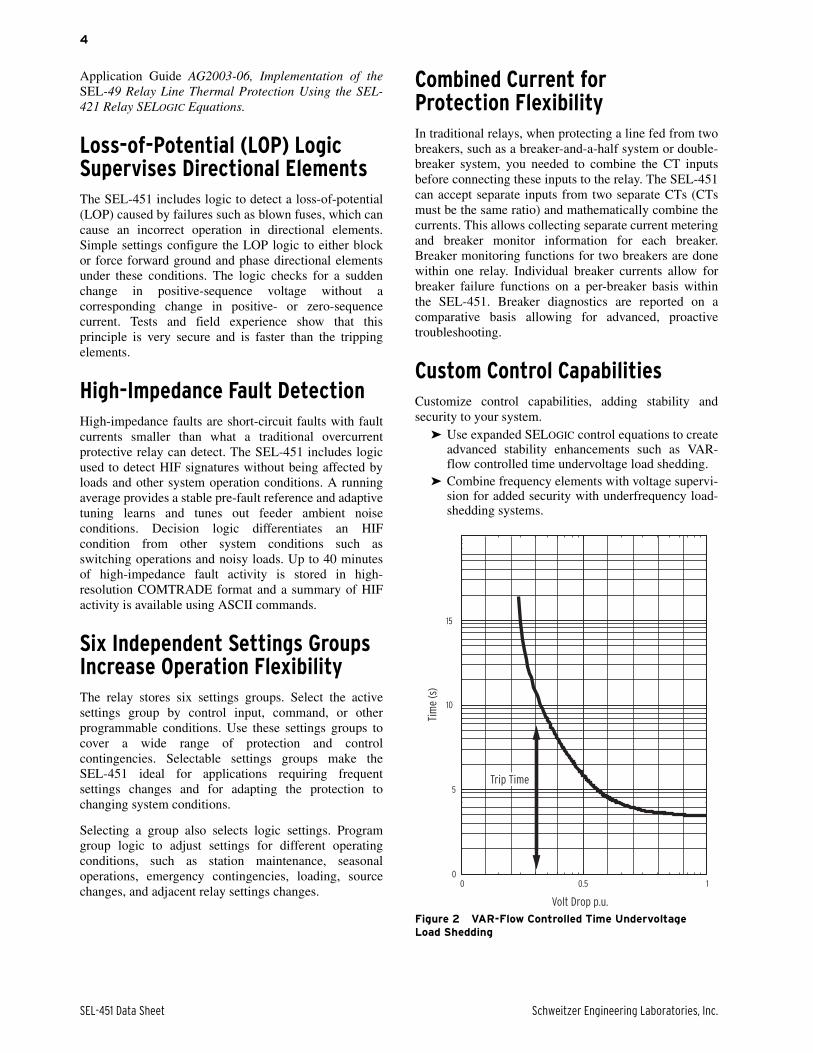
Custom Control CapabilitiesCustomize control capabilities, adding stability andsecurity to your system.
➤ Use expanded SELOGIC control equations to createadvanced stability enhancements such as VAR-flow controlled time undervoltage load shedding.
➤ Combine frequency elements with voltage supervi-sion for added security with underfrequency load-shedding systems.
Figure 2 VAR-Flow Controlled Time Undervoltage Load Shedding
Volt Drop p.u.
Trip Time
Tim
e (s
)
15
10
5
00 0.5 1
Schweitzer Engineering Laboratories, Inc. SEL-451 Data Sheet
5
Control Inputs and OutputsThe standard SEL-451 includes five independent and twocommon inputs, two Form A and three Form C standardinterrupting outputs, and three Form A high-currentinterrupting outputs. The following additionalinput/output (I/O) boards are currently available.
➤ Eight independent inputs, 13 standard Form A andtwo standard Form C contact outputs.
➤ Eight independent inputs, eight high-speed, high-current interrupting Form A contact outputs.
➤ Eight independent inputs, 13 high-current inter-rupting Form A outputs and two standard Form Ccontact outputs.
➤ Twenty-four inputs, six high-speed and two stan-dard Form A contact outputs.
Assign the control inputs for control functions,monitoring logic, and general indication. Each controloutput is programmable using SELOGIC controlequations. No additional I/O boards can be added to the3U chassis; however, one board can be added to the 4Uchassis, and two additional I/O boards can be added tothe 5U chassis. Order standard and additional I/O aseither universal (15-265 Vdc settable pickup) or opto-isolated type.
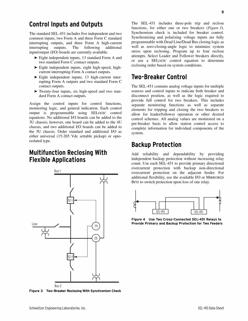
Multifunction Reclosing With Flexible Applications
Figure 3 Two-Breaker Reclosing With Synchronism Check
The SEL-451 includes three-pole trip and reclosefunctions, for either one or two breakers (Figure 3).Synchronism check is included for breaker control.Synchronizing and polarizing voltage inputs are fullyprogrammable with Dead Line/Dead Bus closing logic aswell as zero-closing-angle logic to minimize systemstress upon reclosing. Program up to four recloseattempts. Select Leader and Follower breakers directly,or use a SELOGIC control equation to determinereclosing order based on system conditions.
Two-Breaker ControlThe SEL-451 contains analog voltage inputs for multiplesources and control inputs to indicate both breaker anddisconnect position, as well as the logic required toprovide full control for two breakers. This includesseparate monitoring functions as well as separateelements for tripping and closing the two breakers toallow for leader/follower operation or other desiredcontrol schemes. All analog values are monitored on aper-breaker basis to allow station control access tocomplete information for individual components of thesystem.
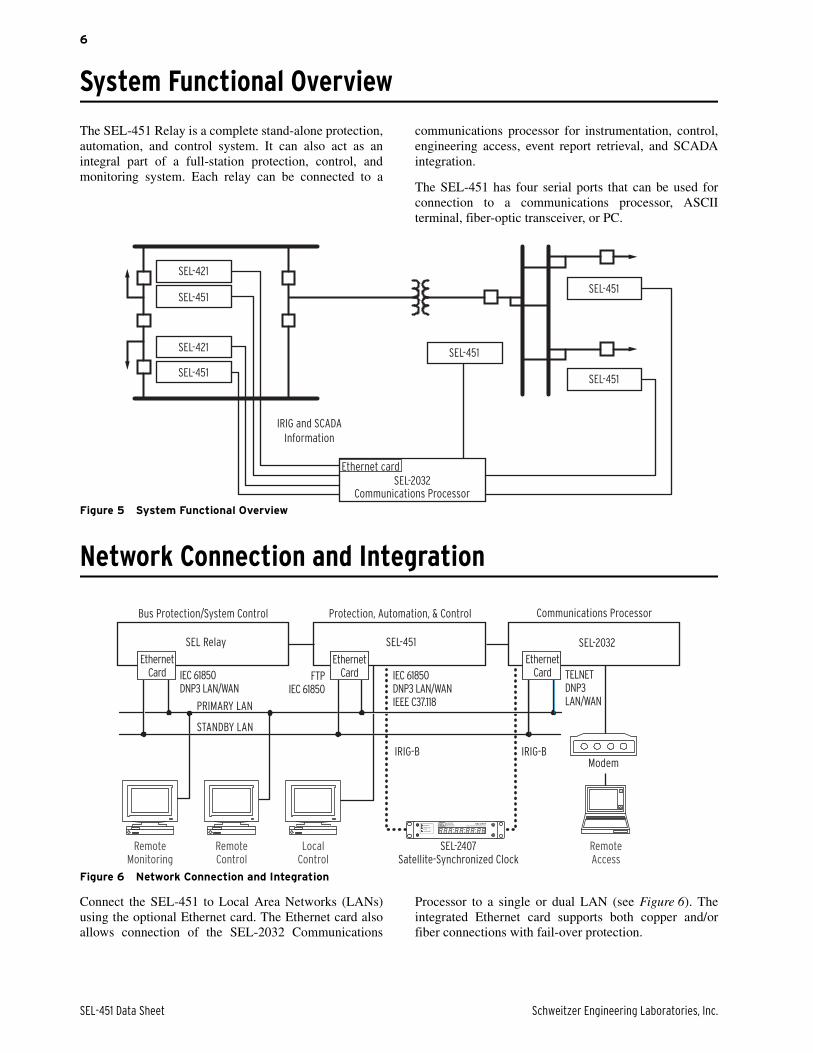
Backup ProtectionAdd reliability and dependability by providingindependent backup protection without increasing relaycount. Use each SEL-451 to provide primary directionalovercurrent protection with backup non-directionalovercurrent protection on the adjacent feeder. Foradditional flexibility, use the available I/O or MIRRORED
BITS to switch protection upon loss of one relay.
Figure 4 Use Two Cross-Connected SEL-451 Relays to Provide Primary and Backup Protection for Two Feeders
52-1
52-2
Line
Bus 2
Bus 1
79
25
SEL-451 SEL-451
SEL-451 Data Sheet Schweitzer Engineering Laboratories, Inc.
6
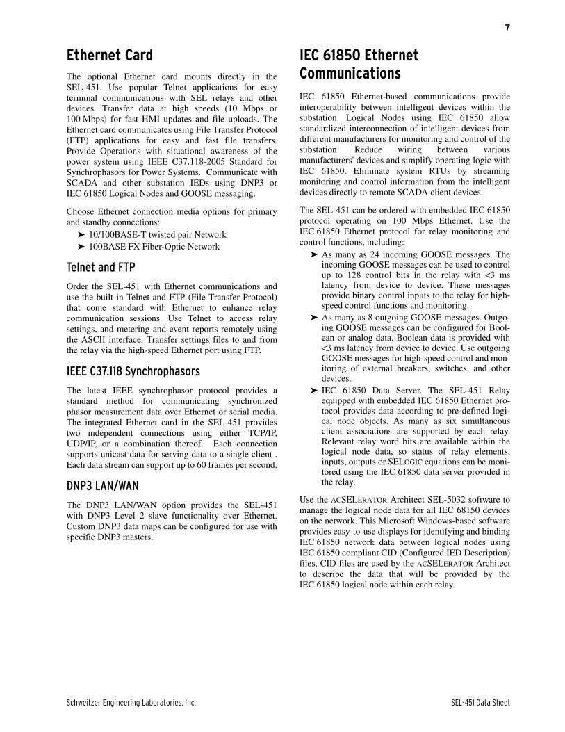
System Functional Overview
The SEL-451 Relay is a complete stand-alone protection,automation, and control system. It can also act as anintegral part of a full-station protection, control, andmonitoring system. Each relay can be connected to a
communications processor for instrumentation, control,engineering access, event report retrieval, and SCADAintegration.
The SEL-451 has four serial ports that can be used forconnection to a communications processor, ASCIIterminal, fiber-optic transceiver, or PC.
Figure 5 System Functional Overview
Network Connection and Integration
Figure 6 Network Connection and Integration
Connect the SEL-451 to Local Area Networks (LANs)using the optional Ethernet card. The Ethernet card alsoallows connection of the SEL-2032 Communications
Processor to a single or dual LAN (see Figure 6). Theintegrated Ethernet card supports both copper and/orfiber connections with fail-over protection.
Communications Processor
IRIG and SCADA
Information
SEL-2032
Ethernet card
SEL-421
SEL-451
SEL-451
SEL-421
SEL-451
SEL-451
SEL-451
Protection, Automation, & Control
STANDBY LAN
PRIMARY LAN
Modem
RemoteAccess
IRIG-BIRIG-B
Bus Protection/System Control
EthernetCard
EthernetCard
EthernetCard
RemoteMonitoring
RemoteControl
LocalControl
Communications Processor
SEL-2032SEL-451SEL Relay
SEL-2407 Satellite-Synchronized Clock
TELNETDNP3LAN/WAN
FTPIEC 61850
IEC 61850DNP3 LAN/WAN
IEC 61850DNP3 LAN/WAN IEEE C37.118
Schweitzer Engineering Laboratories, Inc. SEL-451 Data Sheet
7
Ethernet CardThe optional Ethernet card mounts directly in theSEL-451. Use popular Telnet applications for easyterminal communications with SEL relays and otherdevices. Transfer data at high speeds (10 Mbps or100 Mbps) for fast HMI updates and file uploads. TheEthernet card communicates using File Transfer Protocol(FTP) applications for easy and fast file transfers.Provide Operations with situational awareness of thepower system using IEEE C37.118-2005 Standard forSynchrophasors for Power Systems. Communicate withSCADA and other substation IEDs using DNP3 orIEC 61850 Logical Nodes and GOOSE messaging.
Choose Ethernet connection media options for primaryand standby connections:
➤ 10/100BASE-T twisted pair Network➤ 100BASE FX Fiber-Optic Network
Telnet and FTP
Order the SEL-451 with Ethernet communications anduse the built-in Telnet and FTP (File Transfer Protocol)that come standard with Ethernet to enhance relaycommunication sessions. Use Telnet to access relaysettings, and metering and event reports remotely usingthe ASCII interface. Transfer settings files to and fromthe relay via the high-speed Ethernet port using FTP.
IEEE C37.118 Synchrophasors
The latest IEEE synchrophasor protocol provides astandard method for communicating synchronizedphasor measurement data over Ethernet or serial media.The integrated Ethernet card in the SEL-451 providestwo independent connections using either TCP/IP,UDP/IP, or a combination thereof. Each connectionsupports unicast data for serving data to a single client .Each data stream can support up to 60 frames per second.
DNP3 LAN/WAN
The DNP3 LAN/WAN option provides the SEL-451with DNP3 Level 2 slave functionality over Ethernet.Custom DNP3 data maps can be configured for use withspecific DNP3 masters.
IEC 61850 Ethernet CommunicationsIEC 61850 Ethernet-based communications provideinteroperability between intelligent devices within thesubstation. Logical Nodes using IEC 61850 allowstandardized interconnection of intelligent devices fromdifferent manufacturers for monitoring and control of thesubstation. Reduce wiring between variousmanufacturers' devices and simplify operating logic withIEC 61850. Eliminate system RTUs by streamingmonitoring and control information from the intelligentdevices directly to remote SCADA client devices.
The SEL-451 can be ordered with embedded IEC 61850protocol operating on 100 Mbps Ethernet. Use theIEC 61850 Ethernet protocol for relay monitoring andcontrol functions, including:
➤ As many as 24 incoming GOOSE messages. Theincoming GOOSE messages can be used to controlup to 128 control bits in the relay with <3 mslatency from device to device. These messagesprovide binary control inputs to the relay for high-speed control functions and monitoring.
➤ As many as 8 outgoing GOOSE messages. Outgo-ing GOOSE messages can be configured for Bool-ean or analog data. Boolean data is provided with<3 ms latency from device to device. Use outgoingGOOSE messages for high-speed control and mon-itoring of external breakers, switches, and otherdevices.
➤ IEC 61850 Data Server. The SEL-451 Relayequipped with embedded IEC 61850 Ethernet pro-tocol provides data according to pre-defined logi-cal node objects. As many as six simultaneousclient associations are supported by each relay.Relevant relay word bits are available within thelogical node data, so status of relay elements,inputs, outputs or SELOGIC equations can be moni-tored using the IEC 61850 data server provided inthe relay.
Use the ACSELERATOR Architect SEL-5032 software tomanage the logical node data for all IEC 68150 deviceson the network. This Microsoft Windows-based softwareprovides easy-to-use displays for identifying and bindingIEC 61850 network data between logical nodes usingIEC 61850 compliant CID (Configured IED Description)files. CID files are used by the ACSELERATOR Architectto describe the data that will be provided by theIEC 61850 logical node within each relay.
SEL-451 Data Sheet Schweitzer Engineering Laboratories, Inc.
8
AutomationFlexible Control Logic and Integration FeaturesUse the SEL-451 control logic to do the following:
➤ Replace traditional panel control switches➤ Eliminate RTU-to-relay wiring➤ Replace traditional latching relays➤ Replace traditional indicating panel lights
Eliminate traditional panel control switches with 32 localcontrol points. Set, clear, or pulse local control pointswith the front-panel pushbuttons and display. Programthe local control points to implement your controlscheme via SELOGIC control equations. Use the localcontrol points for such functions as trip testing,enabling/disabling reclosing, and tripping/closing circuitbreakers.
Eliminate RTU-to-relay wiring with 32 remote controlpoints. Set, clear, or pulse remote control points via serialport commands. Incorporate the remote control pointsinto your control scheme via SELOGIC control equations.Use remote control points for SCADA-type controloperations (e.g., trip, close, settings group selection).
Replace traditional latching relays for such functions as“remote control enable” with 32 latching control points.Program latch set and latch reset conditions withSELOGIC control equations. Set or reset the latch controlpoints via control inputs, remote control points, localcontrol points, or any programmable logic condition. Thelatch control points retain states when the relay losespower.
Replace traditional indicating panel lights and switcheswith up to 24 latching target LEDs and up to12 programmable pushbuttons with LEDs. Definecustom messages (i.e., BREAKER OPEN, BREAKER CLOSED,RECLOSER ENABLED) to report power system or relayconditions on the large format LCD. Control whichmessages are displayed via SELOGIC control equationsby driving the LCD display via any logic point in therelay.
Open Communications Protocols
The SEL-451 does not require special communicationssoftware. ASCII terminals, printing terminals, or acomputer supplied with terminal emulation and a serialcommunications port are all that is required. Table 2 listsa synopsis of the terminal protocols.
Rules-Based Settings EditorUse ACSELERATOR QuickSet to develop settings off-line. The system automatically checks interrelatedsettings and highlights out-of-range settings. Settingscreated off-line can be transferred by using a PCcommunications link with the SEL-451. TheACSELERATOR QuickSet interface supports Windows95, 98, 2000, XP, and NT operating systems. OpenCOMTRADE files from SEL and other products.Convert binary COMTRADE Files to ASCII format forportability and ease of use. View real-time phasors andharmonic values.
ACSELERATOR QuickSet Designer SEL-5031
Use the ACSELERATOR QuickSet Designer SEL-5031 tocreate custom views of settings, called ApplicationDesigns, to reduce complexity, decrease the chance oferrors, and increase productivity:
➤ Lock and hide unused settings.➤ Lock settings to match your standard for protec-
tion, I/O assignment, communications, andSELOGIC control equations.
➤ Enforce settings limits narrower than the devicesettings.
➤ Define input variables based on the equipmentnameplate or manufacturer’s terminology or scal-ing and calculate settings from these “friendlier”inputs.
➤ Use settings comments to guide users and explaindesign reasoning.
Schweitzer Engineering Laboratories, Inc. SEL-451 Data Sheet
9
SELOGIC Control Equations With Expanded Capabilities and AliasesExpanded SELOGIC control equations put relay logic inthe hands of the protection engineer. Assign the relayinputs to suit your application, logically combineselected relay elements for various control functions, andassign outputs to your logic functions.
Programming SELOGIC control equations consists ofcombining relay elements, inputs, and outputs withSELOGIC control equation operators (Table 3). Anyelement in the Relay Word can be used in theseequations. The SEL-451 is factory set for use withoutadditional logic in most situations. For complex orunique applications, these expanded SELOGIC functionsallow superior flexibility.
Use the new alias capability to assign more meaningfulrelay variable names. This improves the readability ofcustomized programming. Use as many as 200 aliases torename any digital or analog quantity. The following isan example of possible applications of SELOGIC controlequations using aliases:
=>>SET T <Enter>1: PMV01,THETA
(assign the alias “THETA” to math variable PMV01)2: PMV02,TAN
(assign the alias “TAN” to math variable PMV02)=>>SET L <Enter>1: # CALCULATE THE TANGENT OF THETA2: TAN:=SIN(THETA)/COS(THETA)
(use the aliases in an equation)
Add programmable control functions to your protectionand automation systems. New functions and capabilitiesenable using analog values in conditional logicstatements. The following are examples of possibleapplications of SELOGIC control equations withexpanded capabilities:
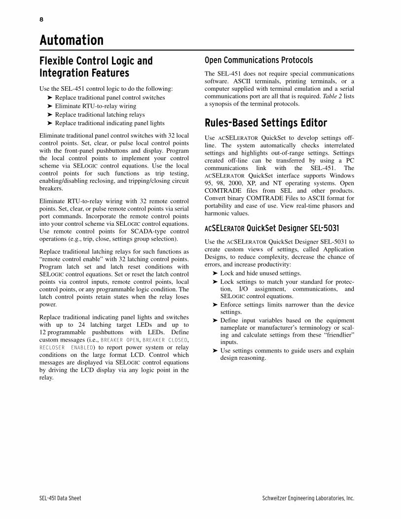
➤ Emulate a motor-driven reclose timer, includingstall, reset, and drive-to-lockout conditions (referto Figure 7).
➤ Scale analog values for SCADA retrieval.➤ Initiate remedial action sequence based on load
flow before fault conditions.➤ Interlock breakers and disconnect switches.
Table 2 Open Communications Protocol
Type Description
ASCII Plain-language commands for human and simple machine communications.
Use for metering, setting, self-test status, event reporting, and other functions.
Compressed ASCII Comma-delimited ASCII data reports. Allows external devices to obtain relay data in an appropriate format for direct import into spreadsheets and database programs. Data are checksum protected.
Extended Fast Meter, Fast Operate, and Fast SER
Binary protocol for machine-to-machine communication.Quickly updates SEL-2032 Communications Processors, RTUs, and other substation devices with metering information, relay element, I/O status,time-tags, open and close commands, and summary event reports. Data are checksum protected.
Binary and ASCII protocols operate simultaneously over the same communications lines so thatcontrol operator metering information is not lost while a technician is transferring an event report.
Ymodem Support for reading event, settings, and oscillography files.
Optional DNP3 Level 2 Slave Distributed Network Protocol with point remapping. Includes access to metering data, protection elements, contact I/O, targets, SER, relay summary event reports, and settings groups.
IEEE C37.118 Phasor measurement protocol.
IEC 61850 Ethernet-based international standard for interoperability between intelligent devices in a substation.
Table 3 SELOGIC Control Equation Operators
Operator Type Operators Comments
Boolean AND, OR, NOT Allows combination of measuring units.
Edge Detection F_TRIG, R_TRIG Operates at the change of state of an internal function.
Comparison >, >=, =, <=, <, < >
Arithmetic +, –, *, / Uses traditional math functions foranalog quantities in an easily programmable equation.
Numerical ABS, SIN, COS, LN, EXP, SQRT
Precedence Control ( ) Allows multiple and nested sets of parentheses.
Comment # Provides for easy documentation of control and protection logic.
SEL-451 Data Sheet Schweitzer Engineering Laboratories, Inc.
10
➤ Restrict breaker tripping in excessive duty situa-tions without additional relays.
➤ Construct a compensated overvoltage element foropen line overvoltage protection.
➤ Hold momentary change-of-state conditions forSCADA polling.
➤ Provide a combination of frequency or rate ofchange of frequency functions.
Figure 7 Motor-Driven Reclose Timer
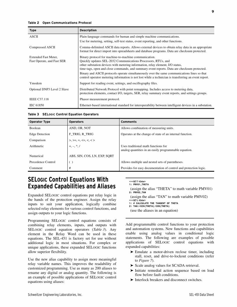
Relay-to-Relay Digital Communications (MIRRORED BITS)The SEL patented MIRRORED BITS technology providesbidirectional relay-to-relay digital communication(Figure 8). In the SEL-451, MIRRORED BITS can operatesimultaneously on any two serial ports for three-terminalpower system operation.
This bidirectional digital communication createsadditional outputs (transmitted MIRRORED BITS) andadditional inputs (received MIRRORED BITS) for eachserial port operating in the MIRRORED BITS
communications mode. Communicated information canincluded digital, analog, and virtual terminal data.Virtual terminal allows operator access to remote relaysthrough the local relay. These MIRRORED BITS can beused to transfer information between line terminals toenhance coordination and achieve faster tripping.MIRRORED BITS also help reduce total pilot schemeoperating time by eliminating the need to close outputcontacts and debounce contact outputs. Use the dual-portMIRRORED BITS communications capabilities for high-speed communications-assisted schemes applied tothree-terminal transmission lines.
CommunicationThe SEL-451 offers the following serial communicationfeatures:
➤ Four independent EIA-232 serial ports.➤ Full access to event history, relay status, and meter
information.➤ Settings and group switching have strong password
protection.➤ DNP3 Level 2 Slave.➤ Patented SEL Fast Message Interleaving of ASCII
and binary data for SCADA communications,including access to SER, relay element targets,event data and more.
➤ Communication of synchronized phasor measure-ment data using either SEL Fast Messaging forSynchrophasors or IEEE C37.118-2005 Standardfor Synchrophasors for Power Systems.
Figure 8 Integral Communication Provides Secure Protection, Monitoring, and Control, as Well as Terminal Access to Both Relays Through One Connection
3rd Reclose(Synchronism Check)
2nd Reclose(Hot Bus/Dead Line)
1st Reclose(Hot Line/Dead Bus)
Reset
Lockout
Fiber-Optic Cable
TXRX
TXRX
SEL-451SEL-451
SEL-2815 SEL-2815OtherRelays
OtherRelays
Bus 1 Bus 2
1 2
Digital, Analog, and Virtual Terminal Data
Schweitzer Engineering Laboratories, Inc. SEL-451 Data Sheet
11
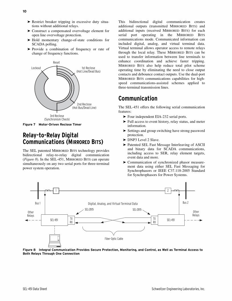
Advanced Front-Panel OperationFront-Panel DisplayThe liquid crystal display (LCD) shows event, metering,setting, and relay self-test status information. The targetLEDs display relay target information as described inFigure 9 and Figure 10 and explained in Table 4.
Figure 9 Factory Default Status and Trip Target LEDs (8 Pushbutton, 16 Target LED Option)
Figure 10 Factory Default Status and Trip Target LEDs (12 Pushbutton, 24 Target LED Option)
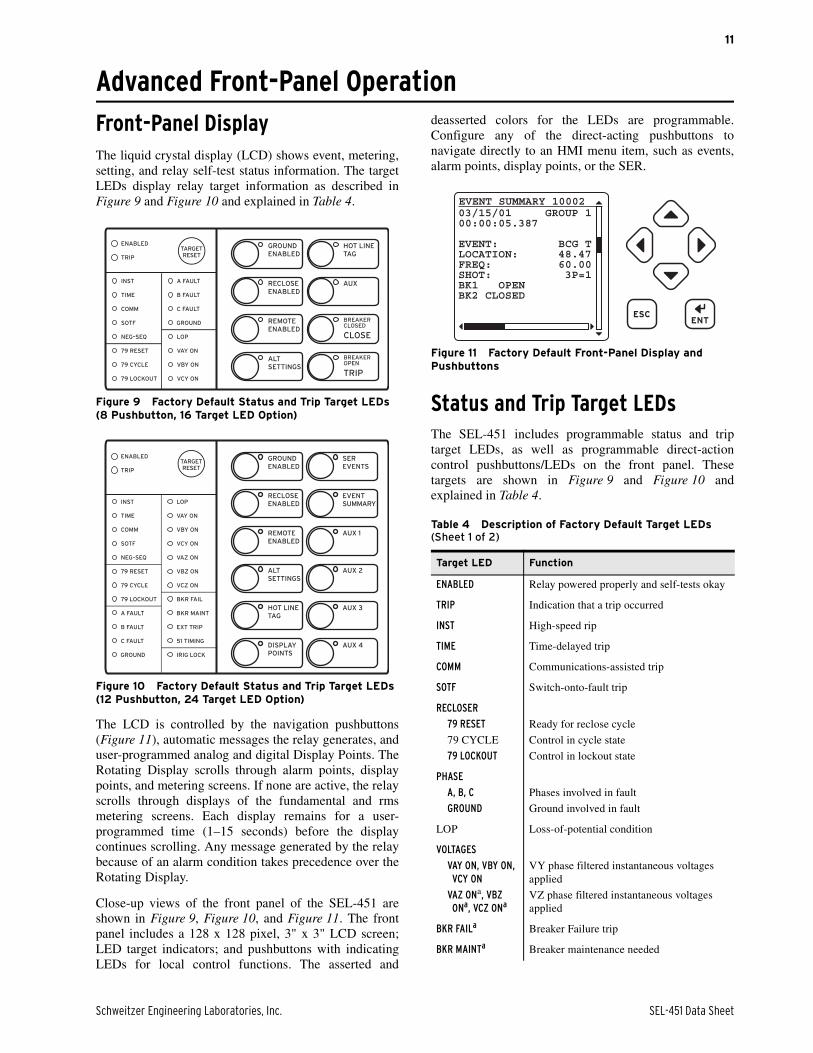
The LCD is controlled by the navigation pushbuttons(Figure 11), automatic messages the relay generates, anduser-programmed analog and digital Display Points. TheRotating Display scrolls through alarm points, displaypoints, and metering screens. If none are active, the relayscrolls through displays of the fundamental and rmsmetering screens. Each display remains for a user-programmed time (1–15 seconds) before the displaycontinues scrolling. Any message generated by the relaybecause of an alarm condition takes precedence over theRotating Display.
Close-up views of the front panel of the SEL-451 areshown in Figure 9, Figure 10, and Figure 11. The frontpanel includes a 128 x 128 pixel, 3" x 3" LCD screen;LED target indicators; and pushbuttons with indicatingLEDs for local control functions. The asserted and
deasserted colors for the LEDs are programmable.Configure any of the direct-acting pushbuttons tonavigate directly to an HMI menu item, such as events,alarm points, display points, or the SER.
Figure 11 Factory Default Front-Panel Display and Pushbuttons
Status and Trip Target LEDsThe SEL-451 includes programmable status and triptarget LEDs, as well as programmable direct-actioncontrol pushbuttons/LEDs on the front panel. Thesetargets are shown in Figure 9 and Figure 10 andexplained in Table 4.
Table 4 Description of Factory Default Target LEDs (Sheet 1 of 2)
Target LED Function
ENABLED Relay powered properly and self-tests okay
TRIP Indication that a trip occurred
INST High-speed rip
TIME Time-delayed trip
COMM Communications-assisted trip
SOTF Switch-onto-fault trip
RECLOSER
79 RESET
79 CYCLE
79 LOCKOUT
Ready for reclose cycle
Control in cycle state
Control in lockout state
PHASE
A, B, C
GROUND
Phases involved in fault
Ground involved in fault
LOP Loss-of-potential condition
VOLTAGES
VAY ON, VBY ON, VCY ON
VAZ ONa, VBZ ONa, VCZ ONa
VY phase filtered instantaneous voltages applied
VZ phase filtered instantaneous voltages applied
BKR FAILa Breaker Failure trip
BKR MAINTa Breaker maintenance needed
03/15/01 GROUP 100:00:05.387
EVENT: BCG TLOCATION: 48.47FREQ: 60.00SHOT: 3P=1BK1 OPENBK2 CLOSED
EVENT SUMMARY 10002
SEL-451 Data Sheet Schweitzer Engineering Laboratories, Inc.
12
The SEL-451 features a versatile front panel that you cancustomize to fit your needs. Use SELOGIC controlequations and slide-in configurable front-panel labels tochange the function and identification of target LEDsand operator-control pushbuttons and LEDs. The blankslide-in label set is included with the SEL-451. Labelsets can be printed from a laser printer using templatessupplied with the relay or hand labeled on supplied blanklabels.
Advanced Display PointsCreate custom screens showing metering values, specialtext messages or a mix of analog and status information.Figure 12 shows an example of how display points canbe used to show circuit breaker information and currentmetering. As many as 96 display points can be created.All display points occupy one, and only one, line on thedisplay at all times. The height of the line isprogrammable as either single or double as shown inFigure 12. These screens become part of theautoscrolling display when the front panel times out.
Figure 12 Sample Display Points Screen
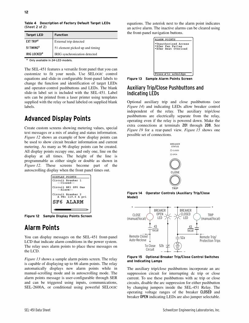
Alarm PointsYou can display messages on the SEL-451 front-panelLCD that indicate alarm conditions in the power system.The relay uses alarm points to place these messages onthe LCD.
Figure 13 shows a sample alarm points screen. The relayis capable of displaying up to 66 alarm points. The relayautomatically displays new alarm points while inmanual-scrolling mode and in autoscrolling mode. Thealarm points message is user-configurable through SERand can be triggered using inputs, communications,SEL-2600A, or conditional using powerful SELOGIC
equations. The asterisk next to the alarm point indicatesan active alarm. The inactive alarms can be cleared usingthe front-panel navigation buttons.
Figure 13 Sample Alarm Points Screen
Auxiliary Trip/Close Pushbuttons and Indicating LEDs
Optional auxiliary trip and close pushbuttons (seeFigure 14) and indicating LEDs allow breaker controlindependent of the relay. The auxiliary trip/closepushbuttons are electrically separate from the relay,operating even if the relay is powered down. Make theextra connections at terminals 201 through 208. SeeFigure 19 for a rear-panel view. Figure 15 shows onepossible set of connections.
Figure 14 Operator Controls (Auxiliary Trip/Close Model)
Figure 15 Optional Breaker Trip/Close Control Switches and Indicating Lamps
The auxiliary trip/close pushbuttons incorporate an arcsuppression circuit for interrupting dc trip or closecurrent. To use these pushbuttons with ac trip or closecircuits, disable the arc suppression for either pushbuttonby changing jumpers inside the SEL-451 Relay. Theoperating voltage ranges of the breaker CLOSED andbreaker OPEN indicating LEDs are also jumper selectable.
EXT TRIPa External trip detected
51 TIMINGa 51 element picked up and timing
IRIG LOCKEDa IRIG synchronization detected
a Only available in 24-LED models.
Table 4 Description of Factory Default Target LEDs (Sheet 2 of 2)
Target LED Function
Circuit Breaker 1 --Closed--
DISPLAY POINTS
Circuit BK1 SF6 Gas --Alarm--
Circuit Breaker 2 A PH= 119.6 A pri
SF6 ALARM
*Unauthorized Access*Xfmr Fan Failes*Xfmr Heat Overload
ALARM POINTS
Press to acknldge
CLOSE(manual/local)
TRIP(manual/local)
Remote Close/Auto-Reclose
Remote Trip/Protection Trips
BREAKEROPENLED
BREAKERCLOSED
LED
43local
To CloseCircuit
43local
52b
52a
52TC
+ +
— —

Schweitzer Engineering Laboratories, Inc. SEL-451 Data Sheet
13
Monitoring and MeteringComplete Metering CapabilitiesThe SEL-451 provides extensive metering capabilities aslisted in Table 5.
Event Reporting and Sequential Events Recorder (SER)Event Reports and Sequential Events Recorder featuressimplify post-fault analysis and help improve yourunderstanding of both simple and complex protectivescheme operations. These features also aid in testing andtroubleshooting relay settings and protection schemes.Oscillo-grams are available in binary COMTRADE andASCII COMTRADE formats.
Oscillography and Event Reporting
In response to a user-selected internal or external trigger,the voltage, current, and element status informationcontained in each event report confirms relay, scheme,and system performance for every fault. Decide howmuch detail is necessary when an event report istriggered: 8 kHz, 4 kHz, 2 kHz, or 1 kHz resolutionanalog data. The relay stores from 5 seconds of data perfault at 1 kHz resolution to 2 seconds per fault at 8 kHzresolution. Reports are stored in nonvolatile memory.Relay settings operational in the relay at the time of theevent are appended to each event report.
Event Summary
Each time the SEL-451 generates a standard event report,it also generates a corresponding Event Summary. This isa concise description of an event that includesrelay/terminal identification, event date and time, faultlocation, phase voltages, fault type at time of trip, andtrip and close times of day.
With an appropriate setting, the relay will automaticallysend an Event Summary in ASCII text to one or moreserial ports each time an event report is triggered.
Sequential Events Recorder (SER)
Use this feature to gain a broad perspective of relayelement operation. Items that trigger an SER entry areselectable and can include input/output change of state,element pickup/dropout, recloser state changes, etc. Therelay SER stores the latest 1,000 entries.
High-Accuracy Time KeepingUsing a combination of IRIG-B and a global positioningsatellite, the SEL-451 can time-tag oscillography towithin 10 µs accuracy. This high accuracy can becombined with the high sampling rate of the relay tosynchronize data from across the system with anaccuracy of better than 1/4 electrical degree. This allowsexamination of the power system state at given times,including load angles, system swings, and other system-wide events. Triggering can be via external signal(contact or communications port), set time, or systemevent. Optimal calibration of this feature requires aknowledge of primary input component (VT and CT)phase delay and error.
A single IRIG-B time-code input synchronizes theSEL-451 time to within ±1 ms of the time-source input.A convenient source for this time code is the SEL-2032Communications Processor (via Serial Port 1 on theSEL-451).
Substation Battery Monitor for DC Quality AssuranceThe SEL-451 measures and reports the substation batteryvoltage for two battery systems. Two sets ofprogrammable threshold comparators and associatedlogic provide alarm and control of two separate batteriesand chargers. The relay also provides dual grounddetection. Monitor these thresholds with the SEL-2032Communications Processor and trigger messages,telephone calls, or other actions.
The measured dc voltage is reported in the METERdisplay via serial port communications, on the LCD, andin the Event Report. Use the event report data to see anoscillographic display of the battery voltage. Monitor thesubstation battery voltage drops during trip, close, andother control operations.
SEL-451 Data Sheet Schweitzer Engineering Laboratories, Inc.
14
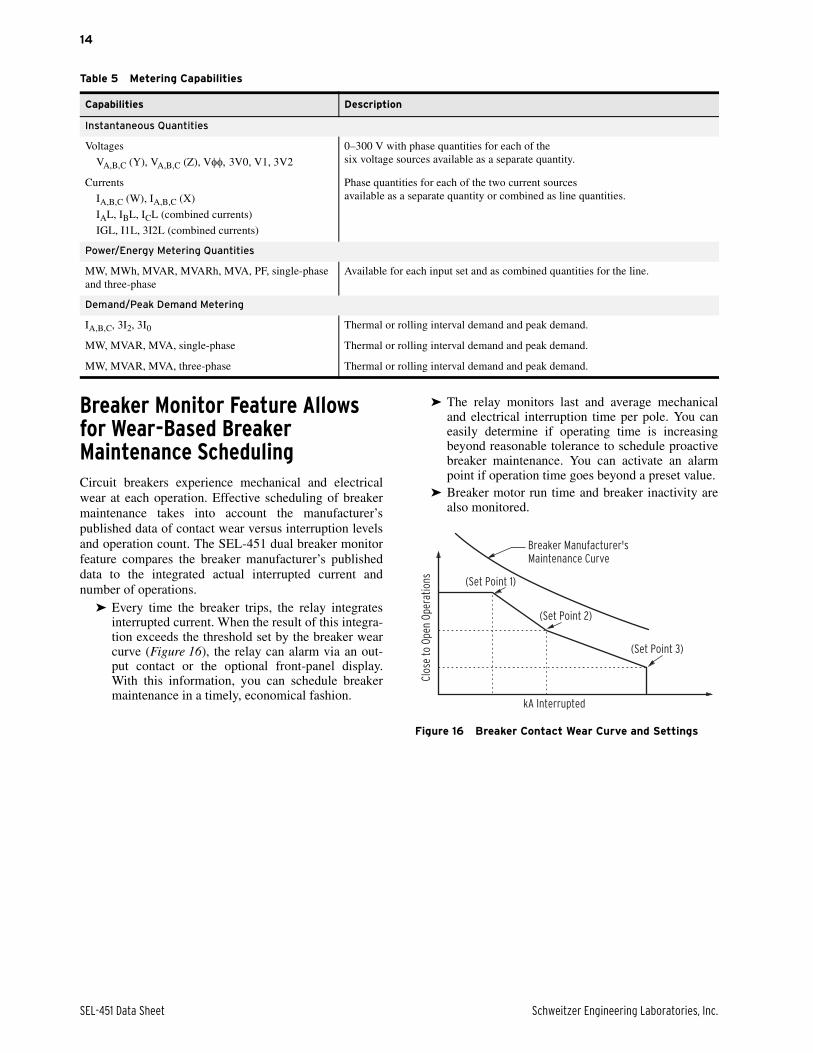
Breaker Monitor Feature Allows for Wear-Based Breaker Maintenance SchedulingCircuit breakers experience mechanical and electricalwear at each operation. Effective scheduling of breakermaintenance takes into account the manufacturer’spublished data of contact wear versus interruption levelsand operation count. The SEL-451 dual breaker monitorfeature compares the breaker manufacturer’s publisheddata to the integrated actual interrupted current andnumber of operations.
➤ Every time the breaker trips, the relay integratesinterrupted current. When the result of this integra-tion exceeds the threshold set by the breaker wearcurve (Figure 16), the relay can alarm via an out-put contact or the optional front-panel display.With this information, you can schedule breakermaintenance in a timely, economical fashion.
➤ The relay monitors last and average mechanicaland electrical interruption time per pole. You caneasily determine if operating time is increasingbeyond reasonable tolerance to schedule proactivebreaker maintenance. You can activate an alarmpoint if operation time goes beyond a preset value.
➤ Breaker motor run time and breaker inactivity arealso monitored.
Figure 16 Breaker Contact Wear Curve and Settings
Table 5 Metering Capabilities
Capabilities Description
Instantaneous Quantities
Voltages
VA,B,C (Y), VA,B,C (Z), V3V0, V1, 3V2
0–300 V with phase quantities for each of thesix voltage sources available as a separate quantity.
Currents
IA,B,C (W), IA,B,C (X)
IAL, IBL, ICL (combined currents)
IGL, I1L, 3I2L (combined currents)
Phase quantities for each of the two current sources available as a separate quantity or combined as line quantities.
Power/Energy Metering Quantities
MW, MWh, MVAR, MVARh, MVA, PF, single-phase and three-phase
Available for each input set and as combined quantities for the line.
Demand/Peak Demand Metering
IA,B,C, 3I2, 3I0 Thermal or rolling interval demand and peak demand.
MW, MVAR, MVA, single-phase Thermal or rolling interval demand and peak demand.
MW, MVAR, MVA, three-phase Thermal or rolling interval demand and peak demand.
kA Interrupted
(Set Point 1)
(Set Point 2)
(Set Point 3)
Breaker Manufacturer'sMaintenance Curve
Clo
se t
o O
pen
Ope
rati
ons

Schweitzer Engineering Laboratories, Inc. SEL-451 Data Sheet
15
Guideform Specification
The microprocessor-based relay shall provide protection,monitoring, control, fault locating, and automation.Relay self-checking functions shall be included. Specificrequirements are as follows:
➤ Overcurrent Fault Protection. The relay shallincorporate selectable operating quantity time-overcurrent elements. Torque control capability(internal and external) shall be provided.
➤ Voltage Transfer Capability. The relay shall beable to change protection voltage source upondetection of loss of potential (LOP). Voltage shallbe capable of changing to a second source con-nected to the relay.
➤ Breaker Failure Logic. The relay shall incorpo-rate dual breaker failure logic for three-pole trip-ping and reclosing. Retrip and transfer trip initiatecontacts shall be provided. Dropout time of thecurrent detection circuit shall be less than onecycle, even in cases with residual dc current in theCT secondary.
➤ Autoreclosing. The relay shall incorporate three-pole reclosing with four separately-set open timeintervals for reclosing. Separately-set reset timesfrom reclose cycle and from lockout shall be avail-able. Reclosing shall be selectable for one or twobreakers.
➤ Synchronism Check. The relay shall include twosynchronism check elements with separate maxi-mum angle settings. The synchronism check func-tion shall incorporate slip frequency and closeangle settings and allow different sources of syn-chronizing voltage (VA, VB, VC, VAB, VBC,VCA).
➤ Independent Trip/Close Pushbuttons. The relayshall include independently operated breakertrip/close switches and indicating lamps. Theswitches and breaker status lamps shall be func-tional regardless of the relay status.
➤ Relay Logic. The relay shall include programma-ble logic functions for a wide range of user-config-urable protection, monitoring, and controlschemes. Logic shall have the ability to use relayelements, math functions, comparison functions,and Boolean logic functions.
➤ High Impedance Fault Detection. The relay shallinclude high-impedance fault detection algorithmscapable of detecting HIF signatures without beingaffected by loads and other system operation con-ditions. The relay shall make high-impedance faultsummary and history information available inASCII format and up to forty minutes of fault datashall be stored in COMTRADE format.
➤ Automation. The relay shall include 32 local con-trol switches, 32 remote control switches, 32 latch-ing switches, and programmable display messagesin conjunction with a local display panel in the
relay. The relay shall be capable of displaying cus-tom messages. Input signals to the relay shall havesettable assertion levels.
➤ Programmable Logic. The relay shall includeprogrammable logic functions for a wide range ofuser-configurable protection, monitoring, and con-trol schemes. Logic shall have the ability to usemath functions, comparison functions, and Bool-ean logic functions.
➤ Alias Naming. The relay shall support the capabil-ity of providing unique name settings (aliases) forup to 200 different relay Boolean and analog quan-tities.
➤ Communications. The relay shall include fourindependent EIA-232 serial ports for external com-munications.
➤ Digital Relay-to-Relay Communications. Therelay shall have send and receive logic elements,and analog and virtual terminal elements in each oftwo communications ports for dedicated relay-to-relay communications.
➤ IEC 61850. The relay shall provide IEC 61850-compliant communications. The IEC 61850 capa-bility shall include GOOSE messaging and definedlogical node data points.
➤ Distributed Network Protocol (DNP). The relayshall incorporate certified DNP3 Level 2 Slaveprotocol and Ethernet DNP3 LAN/WAN commu-nications capability.
➤ Synchrophasors. The relay shall include operationas a phasor measurement and control unit (PMU)following the IEEE C37.118-2005 Standard forSynchrophasors for Power Systems.
➤ IRIG-B Time Input. The relay shall include aninterface port for either a standard or high-accu-racy demodulated IRIG-B time synchronizationinput signal.
➤ High-Accuracy Timing. The relay shall time-tagevent reports to an absolute accuracy of 10 µs.Relays at different system locations shall have thesame absolute timing accuracy.
➤ Password Protection. The relay shall have multi-level passwords to safeguard protection and auto-mation settings.
➤ HMI Display. The relay shall include custom con-figurable display information to display status,analog quantities with units, user-defined labels,and alarm information.
➤ Operator Controls. The relay shall include opera-tor control pushbuttons on the relay front panel.Each pushbutton shall be programmable and acces-sible in the relay control logic.
➤ Fault Locator. The relay shall include a faultlocating algorithm to provide an accurate estimateof fault location without communications channelsor special instrument transformers.

SEL-451 Data Sheet Schweitzer Engineering Laboratories, Inc.
16
➤ Event Reporting and Sequential EventsRecorder. The relay shall automatically recorddisturbance events of up to 2 seconds at 8 kHzsampling rate and 5 seconds at 1 kHz samplingrate. Events shall be stored in nonvolatile memory.The relay shall also include a Sequential EventsRecorder (SER) that stores the latest 1000 entries.
➤ Dual Circuit Breaker Monitor. The relay shallinclude a breaker wear monitor function for twocircuit breakers with a programmable breakermonitor curve. Electrical and mechanical operatingtimes, with comparison between last and averagetimes, shall be monitored and reported.
➤ Dual Substation Battery Monitor. The relay shallmeasure and report the substation battery voltagesboth at steady-state conditions and during tripoperations. Two sets of selectable threshold param-eters shall be provided for alarm and control pur-poses at each battery voltage. DC ground detectionfor two systems shall be included.
➤ Environment. The relay shall be suitable for con-tinuous operation over a temperature range of -40°to +85°C.
➤ PC Interface. The relay shall be capable of beingset by Windows®-based graphical and ASCII ter-minal interfaces.
➤ Configurable Labels. The relay shall include con-figurable labels to customize the targets and opera-tor control pushbuttons.
➤ Terminal Connectors. The relay shall include theability to remove the screw terminal block connec-tors from the back of the relay to disconnect I/O,dc battery monitor, and power without removingeach wire connection.
➤ Warranty. The relay shall have a minimum 10-year worldwide warranty.
➤ Reliability. The manufacturer shall supply theactual measured Mean-Time Between Failures(MTBF) for the device upon request.
➤ Manufacturer. This device shall be manufacturedin the U.S.A.
➤ Warranty Return. The manufacturer shall supporta 72-hour turn-around on all warranty repairs.
Schweitzer Engineering Laboratories, Inc. SEL-451 Data Sheet
17
Front- and Rear-Panel Diagrams
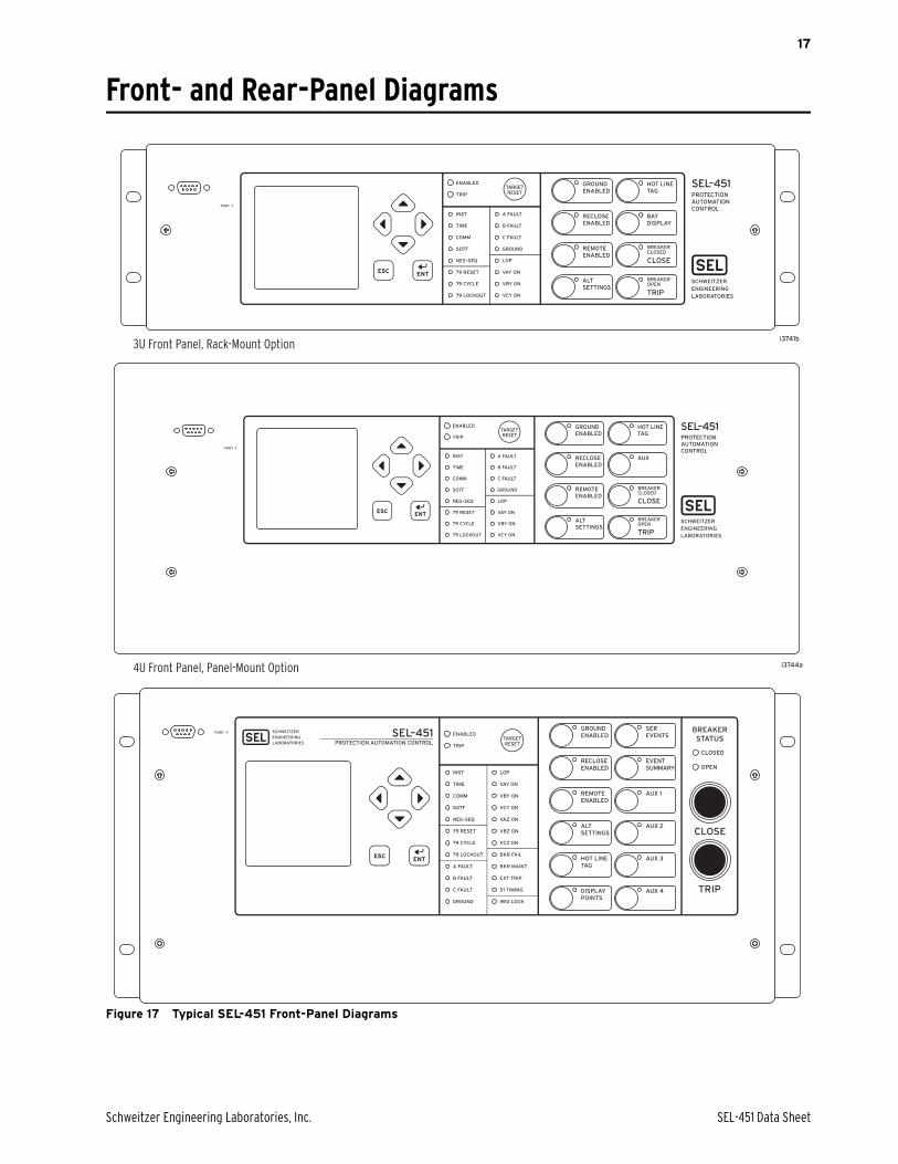
Figure 17 Typical SEL-451 Front-Panel Diagrams
4U Front Panel, Panel-Mount Option
3U Front Panel, Rack-Mount Option
3U Front Panel, Rack-Mount Option
i3744a
SEL-451 Data Sheet Schweitzer Engineering Laboratories, Inc.
18
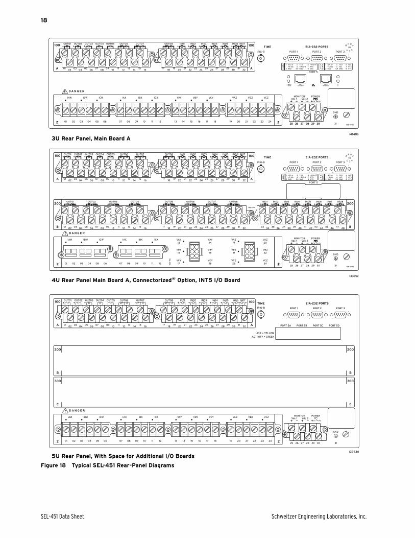
Figure 18 Typical SEL-451 Rear-Panel Diagrams
4U Rear Panel Main Board A, Connectorized® Option, INT5 I/O Board
5U Rear Panel, With Space for Additional I/O Boards
3U Rear Panel, Main Board Ai4148a
I3375c
Schweitzer Engineering Laboratories, Inc. SEL-451 Data Sheet
19
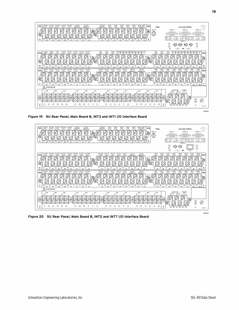
Figure 19 5U Rear Panel, Main Board B, INT3 and INT1 I/O Interface Board
Figure 20 5U Rear Panel, Main Board B, INT2 and INT7 I/O Interface Board
i4149a
421_DS_0022_RearPanel_i4149a_i4150a_b.eps
i4150a
SEL-451 Data Sheet Schweitzer Engineering Laboratories, Inc.
20
Relay Dimensions
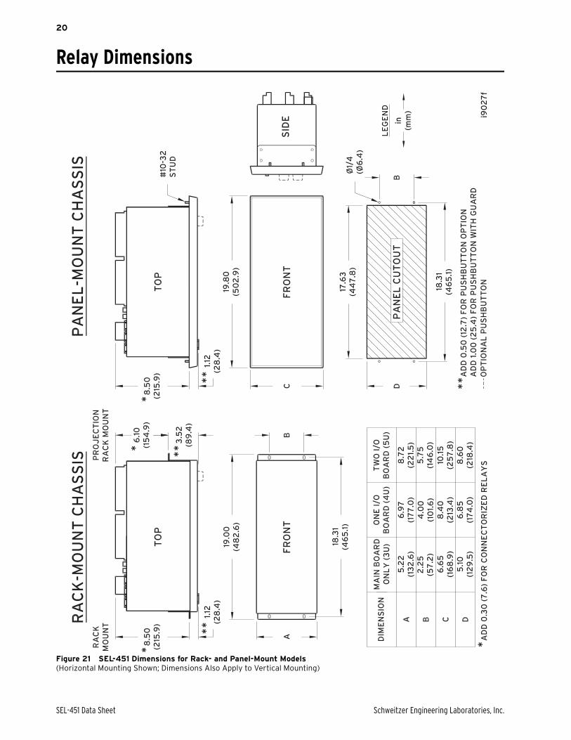
Figure 21 SEL-451 Dimensions for Rack- and Panel-Mount Models(Horizontal Mounting Shown; Dimensions Also Apply to Vertical Mounting)
Schweitzer Engineering Laboratories, Inc. SEL-451 Data Sheet
21
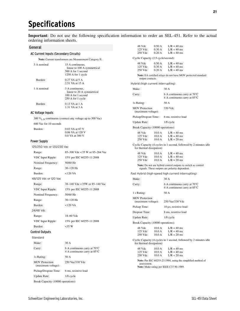
SpecificationsImportant: Do not use the following specification information to order an SEL-451. Refer to the actualordering information sheets.
General
AC Current Inputs (Secondary Circuits)
Note: Current transformers are Measurement Category II.
5 A nominal 15 A continuous,linear to 100 A symmetrical
500 A for 1 second1250 A for 1 cycle
Burden: 0.27 VA at 5 A2.51 VA at 15 A
1 A nominal 3 A continuous, linear to 20 A symmetrical
100 A for 1 second250 A for 1 cycle
Burden: 0.13 VA at 1 A1.31 VA at 3 A
AC Voltage Inputs
300 VL-N continuous (connect any voltage up to 300 Vac)
600 Vac for 10 seconds
Burden: 0.03 VA at 67 V0.06 VA at 120 V0.8 VA at 300 V
Power Supply
125/250 Vdc or 120/230 Vac
Range: 85–300 Vdc <35 W or 85–264 Vac
VDC Input Ripple: 15% per IEC 60255-11:2008
Nominal Frequency: 50/60 Hz
Range: 30–120 Hz
Burden: <120 VA
48/125 Vdc or 120 Vac
Range: 38–140 Vdc <35W or 85–140 Vac
VDC Input Ripple: 15% per IEC 60255-11:2008
Nominal Frequency: 50/60 Hz
Range: 30–120 Hz
Burden: <120 VA
24/48 Vdc
Range: 18–60 Vdc
VDC Input Ripple: 15% per IEC 60255-11:2008
Burden: <35 W
Control Outputs
Standard
Make: 30 A
Carry: 6 A continuous carry at 70°C4 A continuous carry at 85°C
1s Rating: 50 A
MOV Protection (maximum voltage):
250 Vac/330 Vdc
Pickup/Dropout Time: 6 ms, resistive load
Update Rate: 1/8 cycle
Break Capacity (10000 operations):
48 Vdc 0.50 A L/R = 40 ms125 Vdc 0.30 A L/R = 40 ms250 Vdc 0.20 A L/R = 40 ms
Cyclic Capacity (2.5 cycle/second):
48 Vdc 0.50 A L/R = 40 ms125 Vdc 0.30 A L/R = 40 ms250 Vdc 0.20 A L/R = 40 ms
Note: EA certified relays do not have MOV protected standard output contacts.
Hybrid (high current interrupting)
Make: 30 A
Carry: 6 A continuous carry at 70°C4 A continuous carry at 85°C
1s Rating: 50 A
MOV Protection (maximum voltage):
330 Vdc
Pickup/Dropout Time: 6 ms, resistive load
Update Rate: 1/8 cycle
Break Capacity (10000 operations):
48 Vdc 10.0 A L/R = 40 ms125 Vdc 10.0 A L/R = 40 ms250 Vdc 10.0 A L/R = 20 ms
Cyclic Capacity (4 cycles in 1 second, followed by 2 minutes idle for thermal dissipation)
48 Vdc 10.0 A L/R = 40 ms125 Vdc 10.0 A L/R = 40 ms250 Vdc 10.0 A L/R = 20 ms
Note: Do not use hybrid control outputs to switch ac control signals. These outputs are polarity dependent.
Fast Hybrid (high-speed high current interrupting)
Make: 30 A
Carry: 6 A continuous carry at 70°C4 A continuous carry at 85°C
1 s Rating: 50 A
MOV Protection (maximum voltage): 250 Vac/330 Vdc
Pickup Time: 10 s, resistive load
Dropout Time: 8 ms, resistive load
Update Rate: 1/8 cycle
Break Capacity (10000 operations):
48 Vdc 10.0 A L/R = 40 ms125 Vdc 10.0 A L/R = 40 ms250 Vdc 10.0 A L/R = 20 ms
Cyclic Capacity (4 cycles in 1 second, followed by 2 minutes idle for thermal dissipation)
48 Vdc 10.0 A L/R = 40 ms125 Vdc 10.0 A L/R = 40 ms250 Vdc 10.0 A L/R = 20 ms
Note: Per IEC 60255-23:1994, using the simplified method of assessment.
Note: Make rating per IEEE C37.90-1989.
SEL-451 Data Sheet Schweitzer Engineering Laboratories, Inc.
22
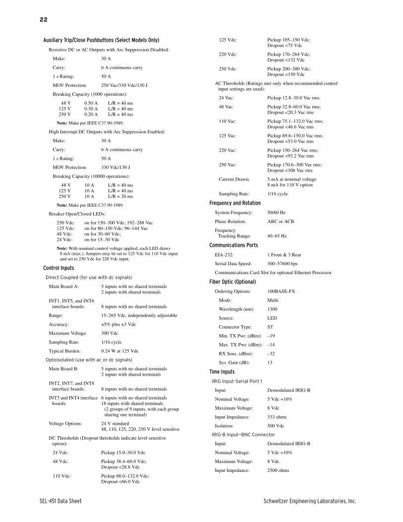
Auxiliary Trip/Close Pushbuttons (Select Models Only)
Resistive DC or AC Outputs with Arc Suppression Disabled:
Make: 30 A
Carry: 6 A continuous carry
1 s Rating: 50 A
MOV Protection: 250 Vac/330 Vdc/130 J
Breaking Capacity (1000 operations):
48 V 0.50 A L/R = 40 ms125 V 0.30 A L/R = 40 ms250 V 0.20 A L/R = 40 ms
Note: Make per IEEE C37.90-1989.
High Interrupt DC Outputs with Arc Suppression Enabled:
Make: 30 A
Carry: 6 A continuous carry
1 s Rating: 50 A
MOV Protection: 330 Vdc/130 J
Breaking Capacity (10000 operations):
48 V 10 A L/R = 40 ms125 V 10 A L/R = 40 ms250 V 10 A L/R = 20 ms
Note: Make per IEEE C37.90-1989.
Breaker Open/Closed LEDs:
250 Vdc: on for 150–300 Vdc; 192–288 Vac125 Vdc: on for 80–150 Vdc; 96–144 Vac48 Vdc: on for 30–60 Vdc;24 Vdc: on for 15–30 Vdc
Note: With nominal control voltage applied, each LED draws 8 mA (max.). Jumpers may be set to 125 Vdc for 110 Vdc input and set to 250 Vdc for 220 Vdc input.
Control Inputs
Direct Coupled (for use with dc signals)
Main Board A: 5 inputs with no shared terminals2 inputs with shared terminals
INT1, INT5, and INT6 interface boards: 8 inputs with no shared terminals
Range: 15–265 Vdc, independently adjustable
Accuracy: ±5% plus ±3 Vdc
Maximum Voltage: 300 Vdc
Sampling Rate: 1/16 cycle
Typical Burden: 0.24 W at 125 Vdc
Optoisolated (use with ac or dc signals)
Main Board B: 5 inputs with no shared terminals2 inputs with shared terminals
INT2, INT7, and INT8 interface boards: 8 inputs with no shared terminals
INT3 and INT4 interface boards:
6 inputs with no shared terminals18 inputs with shared terminals
(2 groups of 9 inputs, with each group sharing one terminal)
Voltage Options: 24 V standard48, 110, 125, 220, 250 V level sensitive
DC Thresholds (Dropout thresholds indicate level-sensitive option):
24 Vdc: Pickup 15.0–30.0 Vdc
48 Vdc: Pickup 38.4–60.0 Vdc;Dropout <28.8 Vdc
110 Vdc: Pickup 88.0–132.0 Vdc;Dropout <66.0 Vdc
125 Vdc: Pickup 105–150 Vdc;Dropout <75 Vdc
220 Vdc: Pickup 176–264 Vdc;Dropout <132 Vdc
250 Vdc: Pickup 200–300 Vdc;Dropout <150 Vdc
AC Thresholds (Ratings met only when recommended control input settings are used):
24 Vac: Pickup 12.8–30.0 Vac rms
48 Vac: Pickup 32.8–60.0 Vac rms;Dropout <20.3 Vac rms
110 Vac: Pickup 75.1–132.0 Vac rms;Dropout <46.6 Vac rms
125 Vac: Pickup 89.6–150.0 Vac rms;Dropout <53.0 Vac rms
220 Vac: Pickup 150–264 Vac rms;Dropout <93.2 Vac rms
250 Vac: Pickup 170.6–300 Vac rms;Dropout <106 Vac rms
Current Drawn: 5 mA at nominal voltage8 mA for 110 V option
Sampling Rate: 1/16 cycle
Frequency and Rotation
System Frequency: 50/60 Hz
Phase Rotation: ABC or ACB
Frequency Tracking Range: 40–65 Hz
Communications Ports
EIA-232: 1 Front & 3 Rear
Serial Data Speed: 300–57600 bps
Communications Card Slot for optional Ethernet Processor
Fiber Optic (Optional)
Ordering Options: 100BASE-FX
Mode: Multi
Wavelength (nm): 1300
Source: LED
Connector Type: ST
Min. TX Pwr. (dBm): –19
Max. TX Pwr. (dBm): –14
RX Sens. (dBm): –32
Sys. Gain (dB): 13
Time Inputs
IRIG Input–Serial Port 1
Input: Demodulated IRIG-B
Nominal Voltage: 5 Vdc +10%
Maximum Voltage: 8 Vdc
Input Impedance: 333 ohms
Isolation: 500 Vdc
IRIG-B Input—BNC Connector
Input: Demodulated IRIG-B
Nominal Voltage: 5 Vdc +10%
Maximum Voltage: 8 Vdc
Input Impedance: 2500 ohms
Schweitzer Engineering Laboratories, Inc. SEL-451 Data Sheet
23
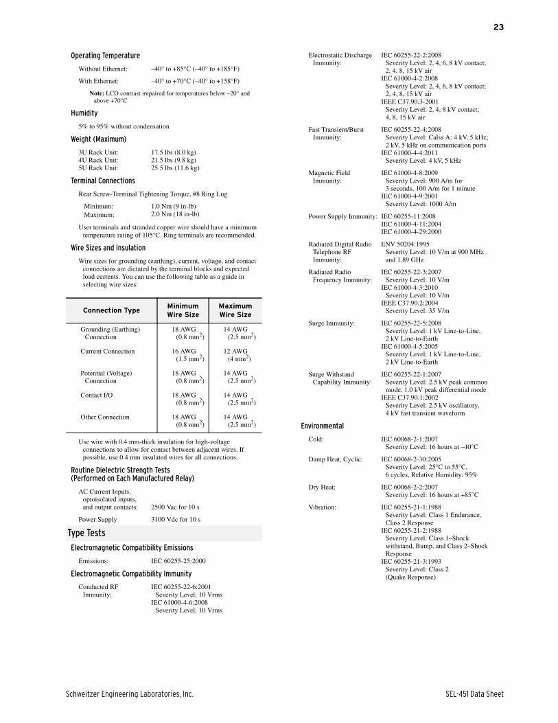
Operating Temperature
Without Ethernet: –40° to +85°C (–40° to +185°F)
With Ethernet: –40° to +70°C (–40° to +158°F)
Note: LCD contrast impaired for temperatures below –20° and above +70°C
Humidity
5% to 95% without condensation
Weight (Maximum)
3U Rack Unit:4U Rack Unit:5U Rack Unit:
17.5 lbs (8.0 kg)21.5 lbs (9.8 kg)25.5 lbs (11.6 kg)
Terminal Connections
Rear Screw-Terminal Tightening Torque, #8 Ring Lug
Minimum:Maximum:
1.0 Nm (9 in-lb)2.0 Nm (18 in-lb)
User terminals and stranded copper wire should have a minimum temperature rating of 105°C. Ring terminals are recommended.
Wire Sizes and Insulation
Wire sizes for grounding (earthing), current, voltage, and contact connections are dictated by the terminal blocks and expected load currents. You can use the following table as a guide in selecting wire sizes:
Use wire with 0.4 mm-thick insulation for high-voltage connections to allow for contact between adjacent wires. If possible, use 0.4 mm insulated wires for all connections.
Routine Dielectric Strength Tests(Performed on Each Manufactured Relay)
AC Current Inputs, optoisolated inputs, and output contacts: 2500 Vac for 10 s
Power Supply 3100 Vdc for 10 s
Type Tests
Electromagnetic Compatibility Emissions
Emissions: IEC 60255-25:2000
Electromagnetic Compatibility Immunity
Conducted RF Immunity:
IEC 60255-22-6:2001Severity Level: 10 Vrms
IEC 61000-4-6:2008Severity Level: 10 Vrms
Connection TypeMinimum Wire Size
Maximum Wire Size
Grounding (Earthing) Connection
18 AWG (0.8 mm2)
14 AWG (2.5 mm2)
Current Connection 16 AWG (1.5 mm2)
12 AWG (4 mm2)
Potential (Voltage) Connection
18 AWG (0.8 mm2)
14 AWG (2.5 mm2)
Contact I/O 18 AWG (0.8 mm2)
14 AWG (2.5 mm2)
Other Connection 18 AWG (0.8 mm2)
14 AWG (2.5 mm2)
Electrostatic Discharge Immunity:
IEC 60255-22-2:2008Severity Level: 2, 4, 6, 8 kV contact;2, 4, 8, 15 kV air
IEC 61000-4-2:2008Severity Level: 2, 4, 6, 8 kV contact;2, 4, 8, 15 kV air
IEEE C37.90.3-2001Severity Level: 2, 4, 8 kV contact;4, 8, 15 kV air
Fast Transient/Burst Immunity:
IEC 60255-22-4:2008Severity Level: Calss A: 4 kV, 5 kHz; 2 kV, 5 kHz on communication ports
IEC 61000-4-4:2011Severity Level: 4 kV, 5 kHz
Magnetic Field Immunity:
IEC 61000-4-8:2009Severity Level: 900 A/m for 3 seconds, 100 A/m for 1 minute
IEC 61000-4-9:2001Severity Level: 1000 A/m
Power Supply Immunity: IEC 60255-11:2008IEC 61000-4-11:2004IEC 61000-4-29:2000
Radiated Digital Radio Telephone RF Immunity:
ENV 50204:1995Severity Level: 10 V/m at 900 MHz and 1.89 GHz
Radiated Radio Frequency Immunity:
IEC 60255-22-3:2007Severity Level: 10 V/m
IEC 61000-4-3:2010Severity Level: 10 V/m
IEEE C37.90.2:2004Severity Level: 35 V/m
Surge Immunity: IEC 60255-22-5:2008Severity Level: 1 kV Line-to-Line, 2 kV Line-to-Earth
IEC 61000-4-5:2005Severity Level: 1 kV Line-to-Line, 2 kV Line-to-Earth
Surge Withstand Capability Immunity:
IEC 60255-22-1:2007Severity Level: 2.5 kV peak common mode, 1.0 kV peak differential mode
IEEE C37.90.1:2002Severity Level: 2.5 kV oscillatory, 4 kV fast transient waveform
Environmental
Cold: IEC 60068-2-1:2007Severity Level: 16 hours at –40°C
Damp Heat, Cyclic: IEC 60068-2-30:2005Severity Level: 25°C to 55°C, 6 cycles, Relative Humidity: 95%
Dry Heat: IEC 60068-2-2:2007Severity Level: 16 hours at +85°C
Vibration: IEC 60255-21-1:1988Severity Level: Class 1 Endurance, Class 2 Response
IEC 60255-21-2:1988Severity Level: Class 1–Shock withstand, Bump, and Class 2–Shock Response
IEC 60255-21-3:1993Severity Level: Class 2 (Quake Response)
SEL-451 Data Sheet Schweitzer Engineering Laboratories, Inc.
24
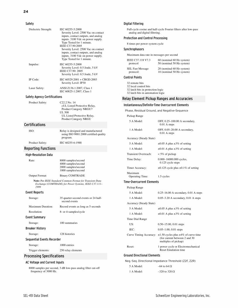
Safety
Dielectric Strength: IEC 60255-5:2000Severity Level: 2500 Vac on contact inputs, contact outputs, and analog inputs. 3100 Vdc on power supply. Type Tested for 1 minute.
IEEE C37.90:2005Severity Level: 2500 Vac on contact inputs, contact outputs, and analog inputs. 3100 Vdc on power supply. Type Tested for 1 minute.
Impulse: IEC 60255-5:2000Severity Level: 0.5 Joule, 5 kV
IEEE C37.90: 2005Severity Level: 0.5 Joule, 5 kV
IP Code: IEC 60529:2001 + CRGD:2003Severity Level: IP30
Laser Safety: ANSI Z136.1:2007, Class 1IEC 60825-1:2007, Class 1
Safety Agency Certifications
Product Safety: C22.2 No. 14cUL Listed Protective Relay, Product Category NRGU7
UL 508UL Listed Protective Relay, Product Category NRGU
CertificationsISO: Relay is designed and manufactured
using ISO 9001:2000 certified quality program.
Product Safety: IEC 60255-6:1988
Reporting Functions
High-Resolution Data
Rate: 8000 samples/second4000 samples/second2000 samples/second1000 samples/second
Output Format: Binary COMTRADE
Note: Per IEEE Standard Common Format for Transient Data Exchange (COMTRADE) for Power Systems, IEEE C37.111–1999
Event Reports
Storage: 35 quarter-second events or 24 half-second events
Maximum Duration: Record events as long as 5 seconds
Resolution: 8- or 4-samples/cycle
Event Summary
Storage: 100 summaries
Breaker History
Storage: 128 histories
Sequential Events Recorder
Storage: 1000 entries
Trigger elements: 250 relay elements
Processing Specifications
AC Voltage and Current Inputs
8000 samples per second, 3 dB low-pass analog filter cut-off frequency of 3000 Hz.
Digital Filtering
Full-cycle cosine and half-cycle Fourier filters after low-pass analog and digital filtering.
Protection and Control Processing
8 times per power system cycle
Synchrophasors
Maximum data rate in messages per second
IEEE C37.118 V7.3 protocol
60 (nominal 60 Hz system)50 (nominal 50 Hz system)
SEL Fast Message protocol:
20 (nominal 60 Hz system)10 (nominal 50 Hz system)
Control Points
32 remote bits32 local control bits32 latch bits in protection logic32 latch bits in automation logic
Relay Element Pickup Ranges and Accuracies
Instantaneous/Definite-Time Overcurrent Elements
Phase, Residual Ground, and Negative-Sequence
Pickup Range
5 A Model: OFF, 0.25–100.00 A secondary, 0.01 A steps
1 A Model: OFF, 0.05–20.00 A secondary, 0.01 A steps
Accuracy (Steady State)
5 A Model: ±0.05 A plus ±3% of setting
1 A Model: ±0.01 A plus ±3% of setting
Transient Overreach: < 5% of pickup
Time Delay: 0.000–16000.000 cycles,0.125 cycle steps
Timer Accuracy: ±0.125 cycle plus ±0.1% of setting
Maximum Operating Time: 1.5 cycles
Time-Overcurrent Elements
Pickup Range
5 A Model: 0.25–16.00 A secondary, 0.01 A steps
1 A Model: 0.05–3.20 A secondary, 0.01 A steps
Accuracy (Steady State)
5 A Model: ±0.05 A plus ±3% of setting
1 A Model: ±0.01 A plus ±3% of setting
Time Dial Range
US: 0.50–15.00, 0.01 steps
IEC: 0.05–1.00, 0.01 steps
Curve Timing Accuracy: ±1.50 cycles plus ±4% of curve time (for current between 2 and 30 multiples of pickup)
Reset: 1 power cycle or Electromechanical Reset Emulation time
Ground Directional Elements
Neg.-Seq. Directional Impedance Threshold (Z2F, Z2R)
5 A Model: –64 to 64
1 A Model: –320 to 320
Schweitzer Engineering Laboratories, Inc. SEL-451 Data Sheet
25
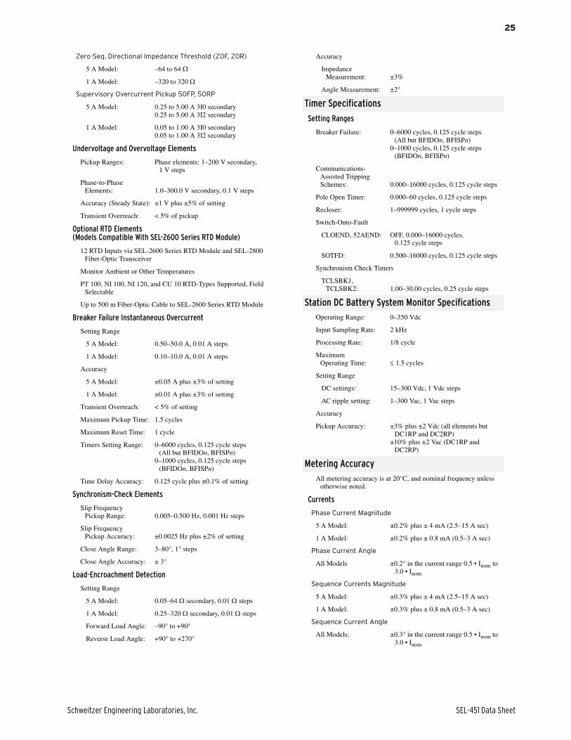
Zero-Seq. Directional Impedance Threshold (Z0F, Z0R)
5 A Model: –64 to 64
1 A Model: –320 to 320
Supervisory Overcurrent Pickup 50FP, 50RP
5 A Model: 0.25 to 5.00 A 3I0 secondary0.25 to 5.00 A 3I2 secondary
1 A Model: 0.05 to 1.00 A 3I0 secondary0.05 to 1.00 A 3I2 secondary
Undervoltage and Overvoltage Elements
Pickup Ranges: Phase elements: 1–200 V secondary, 1 V steps
Phase-to-Phase Elements: 1.0–300.0 V secondary, 0.1 V steps
Accuracy (Steady State): ±1 V plus ±5% of setting
Transient Overreach: < 5% of pickup
Optional RTD Elements(Models Compatible With SEL-2600 Series RTD Module)
12 RTD Inputs via SEL-2600 Series RTD Module and SEL-2800 Fiber-Optic Transceiver
Monitor Ambient or Other Temperatures
PT 100, NI 100, NI 120, and CU 10 RTD-Types Supported, Field Selectable
Up to 500 m Fiber-Optic Cable to SEL-2600 Series RTD Module
Breaker Failure Instantaneous Overcurrent
Setting Range
5 A Model: 0.50–50.0 A, 0.01 A steps
1 A Model: 0.10–10.0 A, 0.01 A steps
Accuracy
5 A Model: ±0.05 A plus ±3% of setting
1 A Model: ±0.01 A plus ±3% of setting
Transient Overreach: < 5% of setting
Maximum Pickup Time: 1.5 cycles
Maximum Reset Time: 1 cycle
Timers Setting Range: 0–6000 cycles, 0.125 cycle steps (All but BFIDOn, BFISPn)
0–1000 cycles, 0.125 cycle steps (BFIDOn, BFISPn)
Time Delay Accuracy: 0.125 cycle plus ±0.1% of setting
Synchronism-Check Elements
Slip Frequency Pickup Range: 0.005–0.500 Hz, 0.001 Hz steps
Slip Frequency Pickup Accuracy: ±0.0025 Hz plus ±2% of setting
Close Angle Range: 3–80°, 1° steps
Close Angle Accuracy: ± 3°
Load-Encroachment Detection
Setting Range
5 A Model: 0.05–64 secondary, 0.01 steps
1 A Model: 0.25–320 secondary, 0.01 steps
Forward Load Angle: –90° to +90°
Reverse Load Angle: +90° to +270°
Accuracy
Impedance Measurement: ±3%
Angle Measurement: ±2°
Timer Specifications
Setting Ranges
Breaker Failure: 0–6000 cycles, 0.125 cycle steps (All but BFIDOn, BFISPn)
0–1000 cycles, 0.125 cycle steps (BFIDOn, BFISPn)
Communications-Assisted Tripping Schemes: 0.000–16000 cycles, 0.125 cycle steps
Pole Open Timer: 0.000–60 cycles, 0.125 cycle steps
Recloser: 1–999999 cycles, 1 cycle steps
Switch-Onto-Fault
CLOEND, 52AEND: OFF, 0.000–16000 cycles, 0.125 cycle steps
SOTFD: 0.500–16000 cycles, 0.125 cycle steps
Synchronism Check Timers
TCLSBK1, TCLSBK2: 1.00–30.00 cycles, 0.25 cycle steps
Station DC Battery System Monitor SpecificationsOperating Range: 0–350 Vdc
Input Sampling Rate: 2 kHz
Processing Rate: 1/8 cycle
Maximum Operating Time: 1.5 cycles
Setting Range
DC settings: 15–300 Vdc, 1 Vdc steps
AC ripple setting: 1–300 Vac, 1 Vac steps
Accuracy
Pickup Accuracy: ±3% plus ±2 Vdc (all elements but DC1RP and DC2RP)
±10% plus ±2 Vac (DC1RP and DC2RP)
Metering AccuracyAll metering accuracy is at 20°C, and nominal frequency unless
otherwise noted.
Currents
Phase Current Magnitude
5 A Model: ±0.2% plus ± 4 mA (2.5–15 A sec)
1 A Model: ±0.2% plus ± 0.8 mA (0.5–3 A sec)
Phase Current Angle
All Models ±0.2° in the current range 0.5 • Inom to 3.0 • Inom
Sequence Currents Magnitude
5 A Model: ±0.3% plus ± 4 mA (2.5–15 A sec)
1 A Model: ±0.3% plus ± 0.8 mA (0.5–3 A sec)
Sequence Current Angle
All Models: ±0.3° in the current range 0.5 • Inom to 3.0 • Inom
SEL-451 Data Sheet Schweitzer Engineering Laboratories, Inc.
26
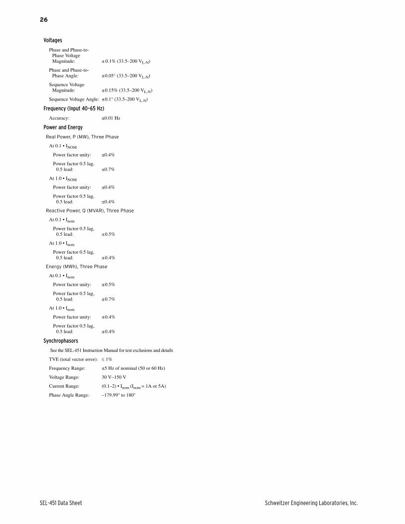
Voltages
Phase and Phase-to-Phase Voltage Magnitude: ± 0.1% (33.5–200 VL-N)
Phase and Phase-to-Phase Angle: ±0.05° (33.5–200 VL-N)
Sequence Voltage Magnitude: ±0.15% (33.5–200 VL-N)
Sequence Voltage Angle: ±0.1° (33.5–200 VL-N)
Frequency (Input 40–65 Hz)
Accuracy: ±0.01 Hz
Power and Energy
Real Power, P (MW), Three Phase
At 0.1 • INOM
Power factor unity: ±0.4%
Power factor 0.5 lag, 0.5 lead: ±0.7%
At 1.0 • INOM
Power factor unity: ±0.4%
Power factor 0.5 lag, 0.5 lead: ±0.4%
Reactive Power, Q (MVAR), Three Phase
At 0.1 • Inom
Power factor 0.5 lag, 0.5 lead: ±0.5%
At 1.0 • Inom
Power factor 0.5 lag, 0.5 lead: ±0.4%
Energy (MWh), Three Phase
At 0.1 • Inom
Power factor unity: ±0.5%
Power factor 0.5 lag, 0.5 lead: ±0.7%
At 1.0 • Inom
Power factor unity: ±0.4%
Power factor 0.5 lag, 0.5 lead: ±0.4%
Synchrophasors
See the SEL-451 Instruction Manual for test exclusions and details
TVE (total vector error): 1%
Frequency Range: ±5 Hz of nominal (50 or 60 Hz)
Voltage Range: 30 V–150 V
Current Range: (0.1–2) • Inom (Inom = 1A or 5A)
Phase Angle Range: –179.99° to 180°

Schweitzer Engineering Laboratories, Inc. SEL-451 Data Sheet
27
Notes

28
© 2003–2012 by Schweitzer Engineering Laboratories, Inc. All rights reserved.
All brand or product names appearing in this document are the trademark or registeredtrademark of their respective holders. No SEL trademarks may be used without writtenpermission. SEL products appearing in this document may be covered by U.S. and Foreignpatents.
Schweitzer Engineering Laboratories, Inc. reserves all rights and benefits afforded underfederal and international copyright and patent laws in its products, including without lim-itation software, firmware, and documentation.
The information in this document is provided for informational use only and is subject tochange without notice. Schweitzer Engineering Laboratories, Inc. has approved only theEnglish language document.
This product is covered by the standard SEL 10-year warranty. For warranty details, visitwww.selinc.com or contact your customer service representative.
*PDS451-01*
SCHWEITZER ENGINEERING LABORATORIES2350 NE Hopkins Court • Pullman, WA 99163-5603 USA
Phone: +1.509.332.1890 • Fax: +1.509.332.7990
Internet: www.selinc.com • E-mail: [email protected]
SEL-451 Data Sheet Date Code 20121207
Notes