Embed Size (px)
Citation preview
fi /i l
2.2152 SOUTH OF BYS* t w010
RECEIVED
JUL22W6
PROJECTS UNIT.
SELCO MINING CORPORATION LIMITED
BLOCK 150-12 DIXIE LAKE AREA
GEOPHYSICAL REPORT
K. Thorsen
Cochenour, Ont.
April, 1976
BLOCK 12
INTRODUCTION
During December 1975 an exploration program
including linecutting and electromagnetic and magnetic
surveys was conducted on the following claims:
KRL 423778 KRL 423779
423780 423781
423782 423783
One in phase conductive zone with an
associated magnetic high was noted.
LOCATION, DESCRIPTION S ACCESS TO PROPERTY
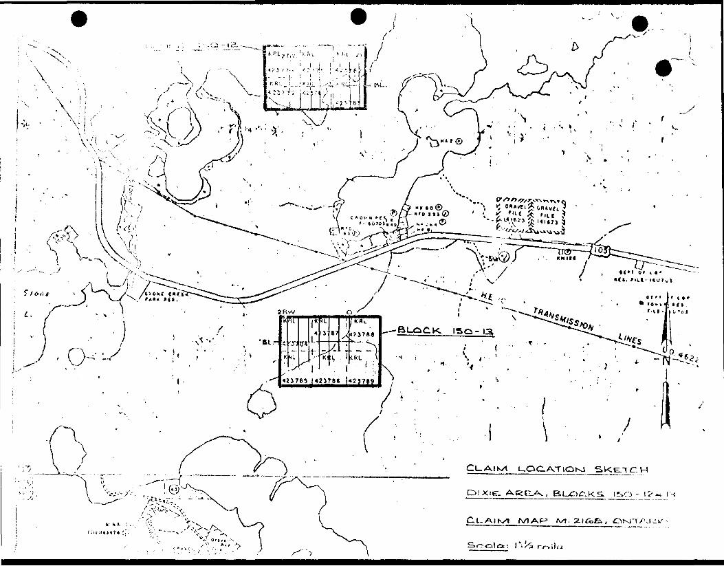
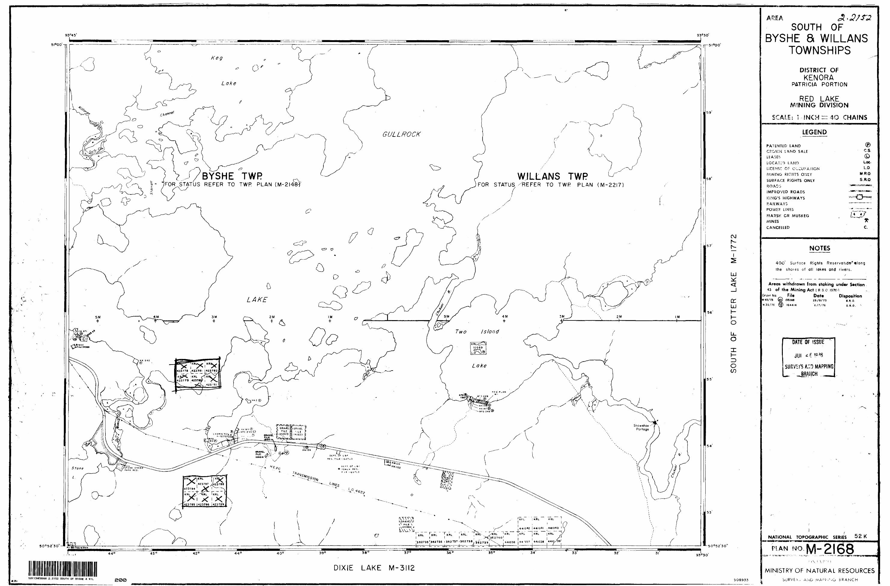
This six claim block lies in the SW quadrantt
of claim sheet M2168, (South of Byshe S Willans Twps) ,
District of Kenora, Patricia Portion.
The block lies on the south shore of Gullrock
Lake. Access is by the Stone River from highway 105 to
Gullrock Lake, hence along the southern shore for 1/2 mile
to the western boundary of the block.
PROPERTY OWNERSHIP
This block is held by Selco Mining Corporation
Limited, Licence T 190.
- 2 -
PRESENTATION OF RESULTS
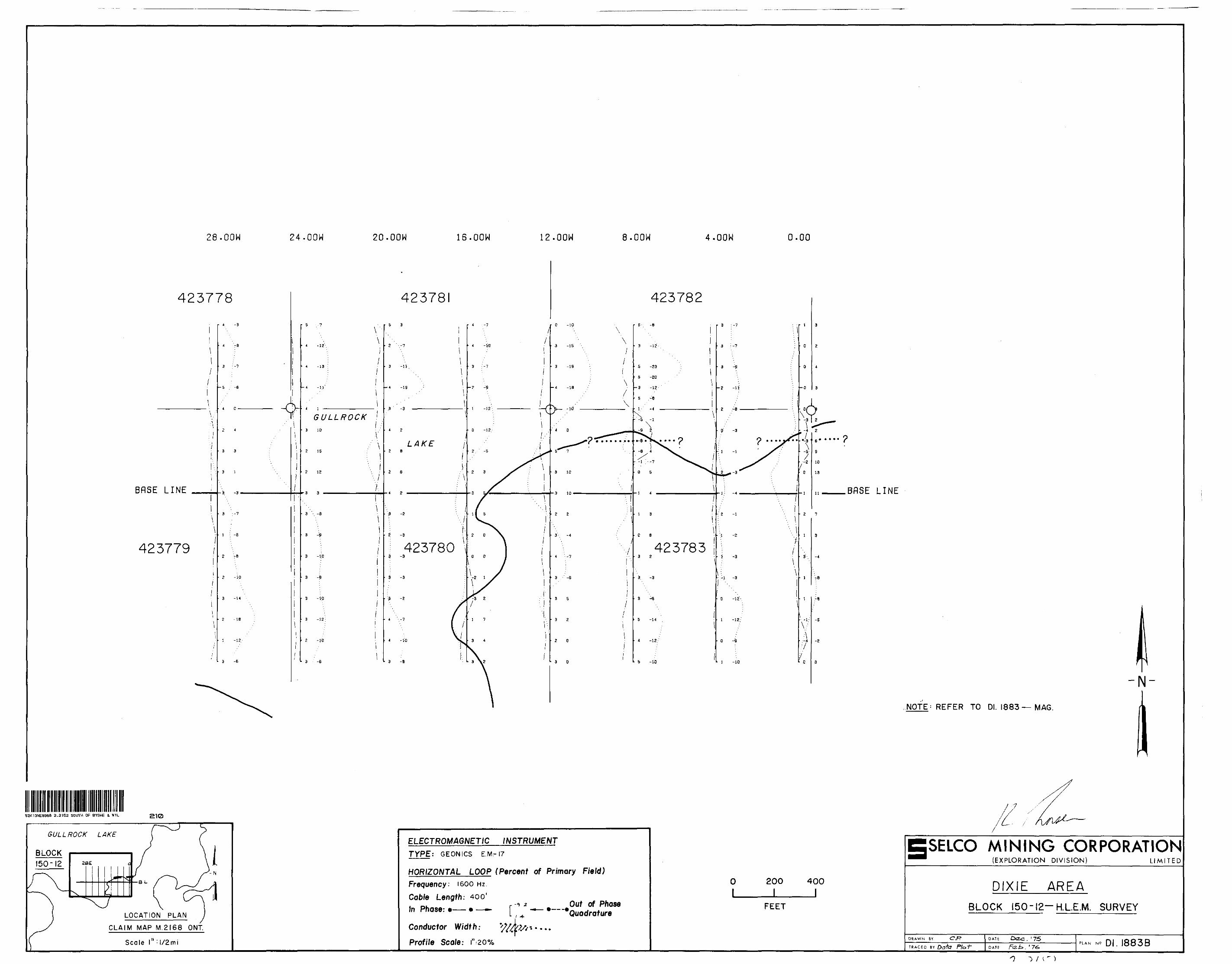
The results of the horizontal loop E.M.
and magnetometer surveys are presented on separate
l" ~ 2 00' plans.
PREVIOUS WORK
No previous mineral exploration work was
noted in the course of the surveys.
GENERAL GEOLOGY
The block lies between the Red Lake and
Uchi Lake greenstone belts in an area of primarilyf
granitic rocks. An outcrop of cherty iron formation was
noted on the shore of Gullrock Lake, west of the claim
block.
GEOPHYSICAL SURVEY DETAILS
Horizontal Loop E.M.
A Geonics E.M. 17 horizontal loop unit was
used with a 400' coil separation and a frequency of
1600 cps. Data was recorded as the in phase and out of
phase percentage of the primary field and plotted as a
graph with a scale of l" ~ 2 0%.
- 3 -
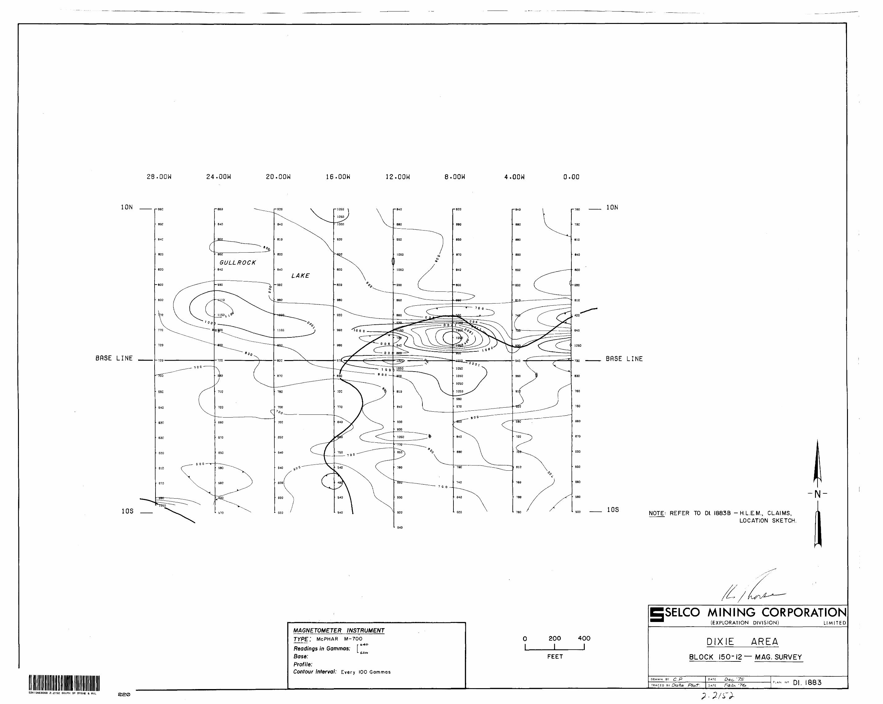
Magnetometer
A McPhar M-700 magnetometer was used with
base stations established at each intersection of cross
lines and the base line. Readings were corrected to
conform, plotted at a scale of l" = 2 00' and contoured.
E.M. readings were taken at 100* intervals
on lines spaced 400' apart. When anomalous conditions
arose, station spacing was dropped to 50'. Magnetic
readings were taken at similar intervals with anomalous
conditions receiving the same treatment.
DISCUSSION OF RESULTSf
A moderate in phase anomaly was recorded
on line O at 2+50N and on line 8W at 2+50N. A direct
magnetic high of from 400 to 800 gammas was also
recorded. These in phase anomalies are usually
indicative of magnetite-rich horizons. Therefore, the
anomalies are probably similar to the cherty iron
formations noted above.
RECOMMENDATIONS
One hole to intersect the anomaly could
be drilled. This should remain a low priority target.
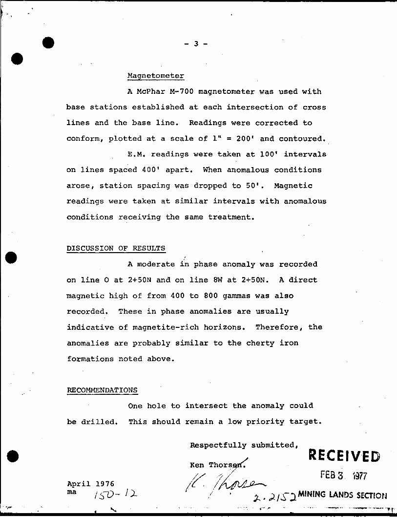
Respectfully submitted,
s R ECEIVEDKen Thorsj^rf./X -fy FE33 '.977
April 1976 /C . //\^MJ2*~^
ma - ' ' MINING UNDS SECTION
J'frf3
52K13NE8968 3 .2152 SOUTH OF BYSHE t WIL 020
PROJECTS MNJI
SELCO MINING CORPORATION LIMITED
DIXIE LAKE AREA BLOCK 150-13
GEOPHYSICAL REPORT
K. Thorsen Cochenour, Ont.
April 1976
-T r
""V"V
\
- S f e-', t
f /., (
^•'V .
1 ; ^:
1 • '.•f\ \ 1 \ .1i /. v /'vV '4 \\ts '"-/- '\ '~ '--'.
r i .v/--•BL-
^--/
•I
K
•1
li.
^
34
rri
RL^
"K!
87
Ir
1
-rT i
(KKi.
*2J788
(Rt \
42J783 I4JST68 1*23769 N\ '
\IV 'l -. SJ '
.1 \ ;x
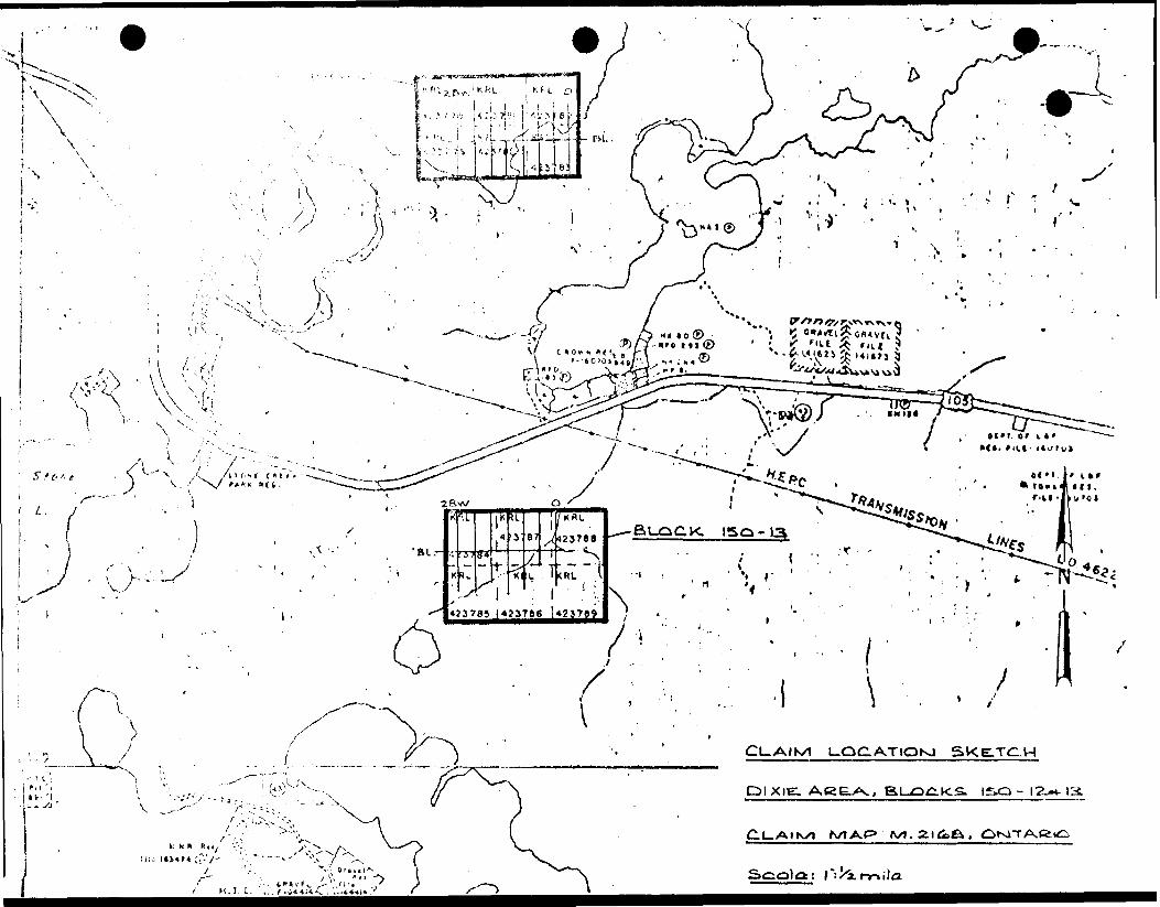
CLAIK/I UOC.ATIOK1 SKE.TC.H
PI XIE.
N/1AP*
INTRODUCTION
During September and October 1975 an exploration programme including linecutting and electromagnetic and magnetic surveys was conducted on the following claims :-
KRL 423784
423785
423786
423787
423788
423789
Two weak conductive zones were noted.
LOCATION DESCRIPTION AND ACCESS TO PROPERTY
This 6 claim block is located in the S.W. quadrant of claim sheet M-2168, (South of Byshe and Willans Twps). District of Kenora, Patricia Portion. The centre of the grid lies approximately one and one-half miles east of the Stone Lake-Highway 105 intersection and a mile south of highway 105.
Access is by way of a N-S trail cut from the high way to the north end of line 28W.
i
PROPERTY OWNERSHIP
The claims are held by Selco Mining Corporation Limited, License T190.
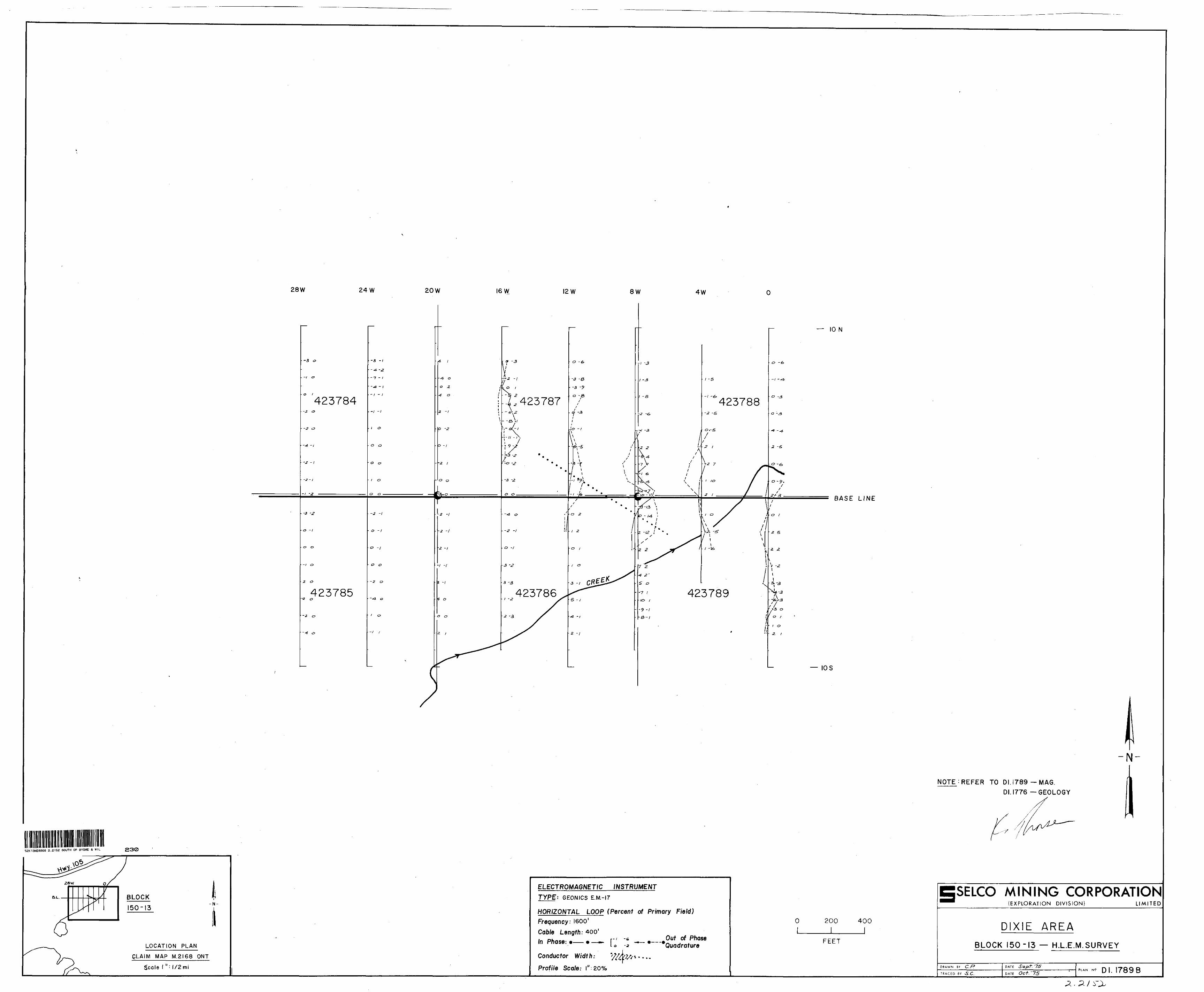
PRESENTATION OF RESULTS
The results of the horizontal loop E.M. and mag netometer surveys are presented on separate I" ss 200 l plans.
PREVIOUS WORK
Evidence of previous mineral exploration was not observed in the course of the surveys.
- 2 -
GENERAL GEOLOGY
This block is within the western portion of the Uchi Lake Greenstone belt. Reconnaissance surveys uncovered sediments, basalts and gabbro within the block.
GEOPHYSICAL SURVEY DETAILS
A Geonics E. M. 17 horizontal loop unit was used with a 400' coil separation and a frequency of 1600 cps. Data was recorded as the in-phase and out-of-phase per centage of the primary field and plotted as a graph with a scale of 1"=20%.
A McPhar M-700 magnetometer was used with base stations established at every intersection of the cross lines and the base line. Readings were corrected to con form, plotted at the scale of l'^200' and contoured.
E. M. and magnetic readings were taken at 100' intervals on lines spaced 400' apart. Anomalous conditions dropped the station spacing to 50' in the respective surveys.
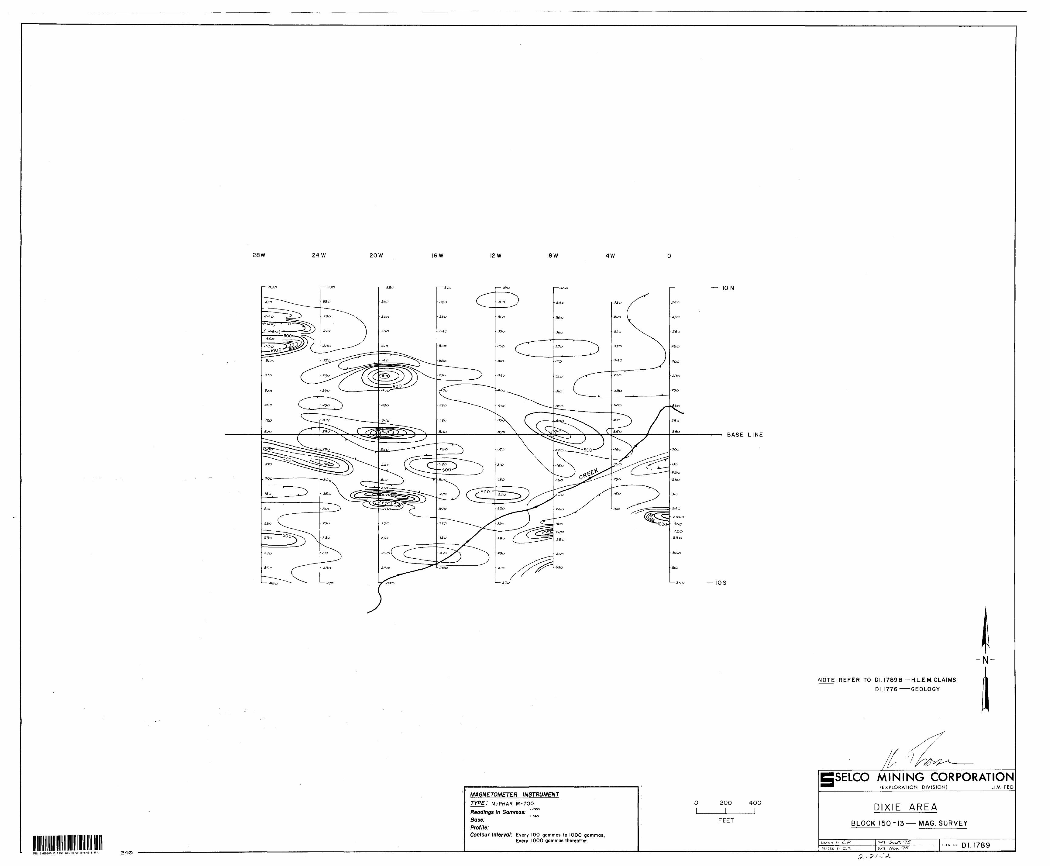
DISCUSSION OF RESULTS
One weak in-phase conductor with a corresponding 100 to 500 gamma magnetic high runs from line 16W, 3+50N to line 8W, 0+50N. The conductor and magnetic high are probably due to magnetite rich sediments.
A similar conductor with higher coincident magnetics (up to 1700 gammas) is apparent from line O, 6+OOS to line 8W, 6+OOS. This anomaly is probably caused by similar conditions to the above.
-LL.
- 3 -
RECOMMENDATIONS
Lines 8W and 4W should be extended to the south to completely cover the conductor indicated. At least one line could be added to the east end of the grid to completely trace the conductor to its full extent.
Respectfully Submitted
X \K. Thorsen
Bb
RECEIVEDFEB3 J977
MINING LANDS SECTION
RECEIVEDFEBb Is/7
LANDS ADMINISTRATION BRANCH
g
GEOPHYSICAL - GEOLC TECHNICAL D^
TO BE ATTACHED AS AN APPENDIX TO TECHNICAL REPORTFACTS SHOWN HERE NEED NOT BE REPEATED IN REPORT
TECHNICAL REPORT MUST CONTAIN INTERPRETATION. CONCLUSIONS ETC.
52K13NE8968 2.3152 SOUTH OF BYSHE t W l L 900
JUL 2 2 1976
PROJECTS UNIT
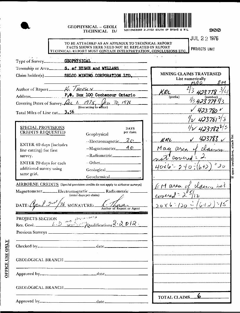
Type of Survey-— Township or Area. Claim holder(s) —
S. of HYSHTT. Anri WTTJ.AMS
RTT.Tr.n MTMTM1
Author of Report. Address.—^-^^—
V. Box 100 Coohenour Ontario
Covering Dates of Surycy fiJtt l- f*?/S
Total Miles of Line cut 3*56(linccutting to twice)
). /'y'//
SPECIAL PROVISIONS CREDITS REQUESTED
ENTER 40 days (includes line cutting) for first survey.
ENTER 20 days for each additional survey using same grid.
,, i-i Geophysical
"Electromagnetic,-Magnetometer-Radiometric
-Other -—————
DAYSpw claim
Geological.Geochemical.
AIRBORNE CREDITS (Special provision credits do not apply to airborne surveys)
Magnetometer. .Electromagnetic, . Radiometric(enter days per claim)
n A TP -- /t w/ J*" f //^ SIGNATURE:——/!-^ Author of Report or Agent
PROJECTS SECTION .W-*" 1 *
Res. Geol. . J) y t-/''':"' '/Ona CK. P
Previous Surveys
Checked by. .date.
GEOLOGICAL BRANCH .
^^
J** Approved by. .date.
GEOLOGICAL BRANCH.
Approved by- .date.
MINING CLAIMS TRAVERSED List numerically
(prefix) ,i (number) .h&tsmth
~~ p
TOTAL CLAIMS.
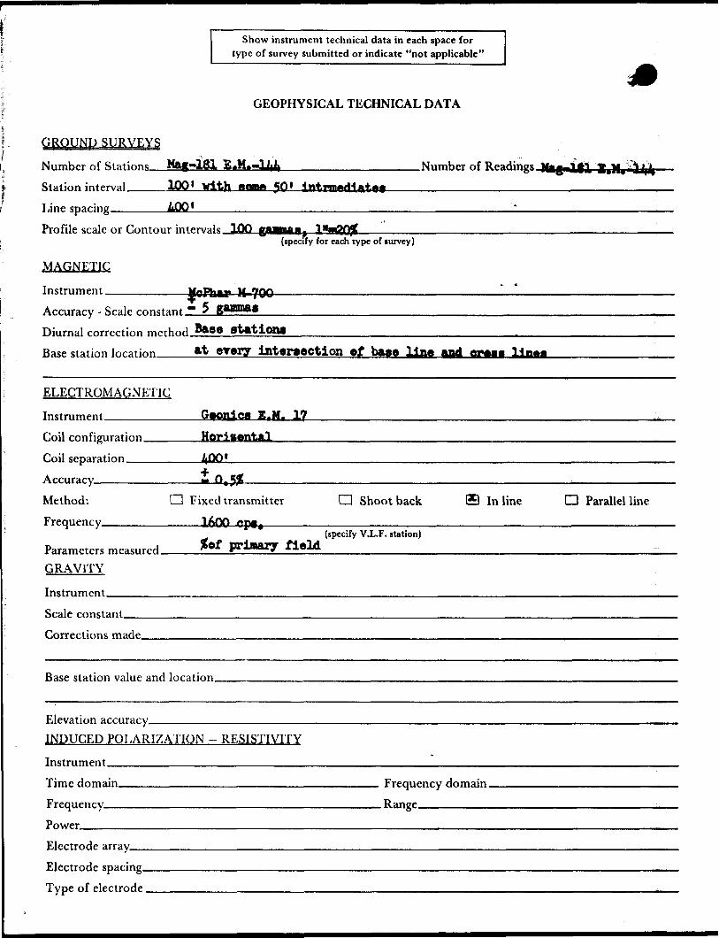
Show instrument technical data in each space for type of survey submitted or indicate "not applicable"
GEOPHYSICAL TECHNICAL DATA
GROUND SURVEYS
Number of StationsStation interval.———100* With mean* *Sftt
Line spacing______400*
.Number of
Profile scale or Contour intervals.
MAGNETIC
Instrument ________
{specify for each type of lurvey)
M-700Accuracy - Scale mnstant ** s gMHM.0Diurnal correction method Base Bt&tlong
Base station location___ftt vrvxy intersection of base "Una 01*4
ELECTROMAGNETIC
Instrument—^..-——.-^- Geonics E.M. 3/ZLCoil configuration. Coil separation__ Accuracy————— Method:
Horisental
JiDO'
Frequency.CZ3 Fixed transmitter
___CD Shoot back In line D Parallel line
Parameters measured. GRAVITY
Instrument——————
gof primary field(specify V.L.F. station)
Scale constant.
Corrections made.
Base station value and location.
Elevation accuracy-^————. INDUCED POLARIZATION
Instrument——^^-^———-
RESISTIVITY
Time domain. Frequency——
Frequency domain. . Range^—————^
Electrode array—— Electrode spacing. Type of electrode,
150-33 File.
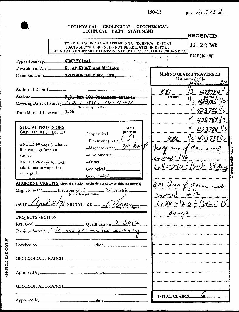
GEOPHYSICAL - GEOLOGICAL - GEOCHEMICAL TECHNICAL DATA STATEMENT
OFFICE USE ONLY
RECEIVEDTO BE ATTACHED AS AN APPENDIX TO TECHNICAL REPORT 1 1 1 1 o o * QJC
FACTS SHOWN HERE NEED NOT BE REPEATED IN REPORT *)VL 6 A 13/0 TECHNICAL REPORT MUST CONTAIN INTERPRETATION, CONCLUSIONS ETC.
* f r^
Typp nf Survpy GEOPHYSICAL '
Tnwnchip nr Arpa S. Of BYSHE *tlrf UTLT.iNfi
riaim v,nidpr(e) SKTr.fiMTJiTVfF OORP, LTP.
Author of Report
rVwPring HatPC ^f Rnrvpy St: PT f .tf~X~, rtfS 3i tCi~lX(linccutting to office)
O CLTotal Miles of Line rut , ,i?.*/0
SPECIAL PROVISIONS HAVSCREDITS REQUESTED f, M h ,5ka, per claim
( 15ENTER 40 days (includes I JL. jjT^ d? line cutting) for first Magnetometer —— ?1 ^^ 1survey. —Radiometric
F,NTF,R W d ays for rach -Otheradditional survey using r,pn\na\r*\same grid.
AIRBORNE CREDITS (Special provision credits do not apply to airborne lurveyt)
Mapnptometer Rlprtromapnptir RaHiomptrir(enter days per claim) ,
/? J2/-7/ S-77PATR- C -C j/fru-r -**/ /J SIONATTIRR: X - /A,fl4Lt. ^/ ' ' Author of Report or Agent
PROJECTS SECTION...^.Cjft/^l
Rfts.lwfinl.. Oiialifirations *^ CX U / "^y O PrPVJous Surveys . .', -^ --J-t-O O^\.f-v^..x^--t^o sa^**\^v~4*j*.
v g
nhprkpH hy Hatp
OROLOGICAL HRANr.H
Approved hy ria t p
nRnT.nr,Tr.AT. RKAMHH
Approved hy datp
- . . s. - PROJECTS UNITi
MINING CLAIMS TRAVERSED List numerically s .
M A& &H
KM* k wmt 1(prefix) l (number) i,
j X ff'?37f f* ITS
'***J /8o i i
^rt/J /O 7 '{ ^
y/ j) ?7j?J? '/3
4^6 llv*SJ3711 fjrk*4* a***. J dU^^^z,frfY***ji ~ ' 'b
lr*fc'M0 1 TL*)-#tfat* *"- iMMHWM^,^^
fy'Pv (Afa+^tfc dLju*m^, *7kj*fe*\ } i
(s* w - /^ o - 7Z/^) : / x^^vO ''
TOT AT, CI, ATMS ^
s
13
|
M
tt
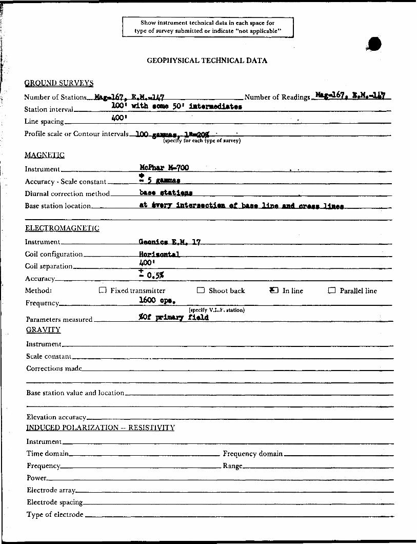
Show instrument technical data in each space for type of survey submitted or indicate "not applicable"
GEOPHYSICAL TECHNICAL DATA
GROUND SURVEYS
Number of Sfat.inns Ma.gnJ.67 1 E*Wt-JIA7______________Number of100' With BflBM 50'Station interval_____________ ~*~* sv400'
Line spacing——^————Profile scale or Contour intervals ^jpp gfngmflf, '
(specify for each type of survey)
MAGNETIC
Instrument ______________MePhar &-700.————————
Accuracy - Scale constant _____** 5Diurnal correction method_____base Base station location
ELECTROMAGNETIC
Instrument_______________Q^anfrQg E.Mt 17Coil configuration—^——————^ -i - iOO' Coil separation____________7^
Accuracy————————————Method: CD Fixed transmitter D Shoot back C In line O Parallel line Frequency______________+BW Op*t————,^—-————————.,..^^———^^-————^—--——-———
(specify V.L.F. station)Parameters measured________ff)f pplaaiy field—^———-..,..^———.,.——.——,^——^.^.^ GRAVITY
Instrument.Scale constant.Corrections made.
Base station value and location.
Elevation accuracy—^^—-—^————.^———. INDUCED POLARIZATION - RESISTIVITY
Instrument^—————--^——--—.^^———.^.^—.Time domain___________________________ Frequency domain. Frequency_____________________________ Range_______ Power____________________________________________Electrode array__ Electrode spacing. Type of electrode,
93045'
5I000'-
t t.
50 0 52 30
GULLROCK
BYSHE TWP WILLANS TWPFOR STATUS /REFER TO TWP PLAN (M-2217)FOR STATUS REFER TO TWR PLAN (M-2I48-T
. x423785 1423786 423789
4410*2 441041 44I04Q
362735'362736 i 362737 -362738 .i.-,, 9 441036 44 037 441038L - . -L.
DIXIE LAKE M-3II2
C\J
l 5
LJ
o:UJh-h- o
LL. O
Xh-ID O CO
SOUTH OFBYSHE a WILLANS
TOWNSHIPS
DISTRICT OFKENORA
PATRICIA PORTION
RED LAKE
4O CHAINS
PATENTED L AND
CROWN LAND S ALE
LEASED
LOCATED LAND
UCEMS: o r- O CCUPATIONMINING RIGHTS O MiY
SURFACE RIGHTS ONLY
ROADS
IMPROVED ROADS
KING'S HfGHWAYS
RAILWAYS
POWER LIMES
MARSH GR MUSKEG
MINES
CANCELLED
C.S.
LOC.
L.O
MRO
S.R.O
C.
NOTES
40O Surface Rights
the shores of all lakes and rivers.
Areas withdrawn from staking und*r Section 43 of the Mining Act l R so 1970)
Order NO File Da t* DispositionW.45/7S MjO 135388
W.35/76 W) 1644(425/9/73
"e/r/769.R.O.
S.R.O.
DATE OF fSSUE '
JUI **M0?6
SURVE/S A;:;) MAPPING
S2KI3NE8968 2.2152 SOUTH OF BYSHE A WIL 200 508933
NATIONAL TOPOGRAPHIC SERIES 52 K niii*i iiiMiiainii 9 '~ mi
PIAN M-2168M\ l \ [' "fi
MINISTRY OF NATURAL RESOURCES^ AND MAPPING BRANCH
28-OOW 24.00W
423778
BflSE LINE
423779
4 -3
4 -8
3 ;-7
-5 -6
4 O
2 4
3 3
3 l
3 -3
3 -7
-6
2 -i-0
3 -14
2 -18
l -12'
3 -6
52KI3NE8968 2.2152 SOUTH OF BYSHE i. W IL
GULL ROCK LAKE
BLOCK150-12
LOCATION PLAN
CLAIM MAP M.2F68 ONT.
Scale l":|X2mi
5 -7
4 -12'
4 -13
-11
4 l
3 10
2 15
2 12
3 3
3 - -6
3 -9
3 -9
3 -1-0
3 -12
2 -10
3 -6
20-OOW 16.00W 12.00W 8.00W 4.00W
423781 423782
2 --7
3 -It
-4 -19
3 -3
4 2
2 e
2 6
LAKE
4 2
3 -2
2 -3
4237803 -3
3 -3
3 -2
4 --7
4 -1-0
3 -8
ELECTROMAGNETIC I NSTRUMENT
TYPE t G EONICS EM.-17
HORIZONTAL LOOP (Percent of Primary Field) Frequency; i soo HZ
Cable Length; 4 00'In Phase: e— * ——
Conductor Width:
Profile Scale: i":20 07o
r; •—— ^ wOuf of Phase Quadrature
0.00
BflSE LINE
-N-
^ REFER TO DI. 1883 MAG.
L
o L
200l
400
l
FEET
ESELCO MINING CORPORATION(EXPLORATION D IVISION) LIMITED
DIXIE AREA
BLOCK I50-I2-H.LE.M. SURVEY
DRAWN BY C".F?
TRACED BY Ptoi~
DATE CXZtZ . ' 75
DATEPLAN N9 DI. I883B
ION
BflSE LINE
IDS
S2K13NE8968 2.2152 SOUTH OF BYSHE 4 WIL
28.00W 24-OOW 20.00W 16-OOW 12.00W 8-OOW 4.00W
1 640
MAGNETOMETER INSTRUMENT TYPE: M CPHAR M-700
r
Readings m Gammas:L
Base:Profile:Contour Interval: E very 100 Gammas
0
o.oo
800
GULLROCK840
1-760
73C
810
840
800
680
810
420
640
1250
730
830
760
760
660
670
650
600
680
580
L 500
ION
BflSE LINE
-fl
NOTE: REFER TO DI. I883B - H.L.EM., CLAIMS,LOCATION SKETCH.
200 400
FEET
E™
SELCO MINING CORPORATION(EXPLORATION D IVISION) LIMITED
DIXIE AREA
BLOCK 150-12 MAG. SURVEY
DRAWN BY C . P-
TRACED BY
DATE - ' 7S
DATE DI
220
28W 24W 20W 16 W I2W 8W 4W 0
- -3
0 '
- -2
•-4 -;
-2 -i
-1 -2
-3-1
423784
' --4 ~ l
' t - l
. l O
a o
O c?
t O
-3 '2
-y o
423785-2
-2 o
-4- o
' 2,
2. -1
0 -
O -l
-z i
- O o
7
"
o o "T
o -y
o -;
0 0
-2 0
-•4. o
l O
2 -f
~2 -f
•2 -f
J - 1
f 0
-3
-\ 423787\
-3 -t
t-t
-x
o -y
3 --
3 -3
423786
0 -
-3 -B
l -3
,o - t
t -8
•2 -
•2. 2
\ A
/O 2
l 2
a i
i o
5 -;
•4 -1
2 -t
2 -
2. 2
72.
-7 I
-so i
-9 -l
423788-5
423789
0 -
0 -.3
.2 - B
2. 2.
1 -*lv
,//- *3 O
* O
.z ;
— 10 N
BASE LINE
— l o s
NOTE: REFER TO DI.I789 — MAG.DI.I776 —GEOLOGY
52K13NE8968 2. Z152 SOUTH OF BYSHE A VI l L 230
LOCATION PLAN
CLAIM MAP M.2I68 ONT"Scale l: 1/2 mi
ELECTROMAGNETIC I NSTRUMENT
TYPE: G EONICS E.M.-I7
HORIZONTAL LOOP ( Percent of Pn'mory Fie W J Frequency: 160O 1Cable Length: 400' In Phase:*—s—— [ Out of Phase
QuadratureConductor Width:
Profile Scale; l ":20 07o
0 200 400
FEET
ESELCO MINING CORPORATION^™ (EXPLORATION DIVISION) LIMITED
- w . -- A - - .D XiE AREA
BLOCK 150-13 — H. L. E. M. SURVEY
DRAWN BY C.P
TRACED 8V -S.C.
DATE
DATE Ocf.'TSPlAN N9 Q f
2 7 O;
28 W 24 W 20 W 16 W 12 W 8W 4W O
330 330 380 ION
BASE LINE
10 S
NOTE:REFER TO DI. I789B — H.L.E.M. CLAIMS
DI.1776——GEOLOGY
52K13NEB9B8 2.2152 SOUTH OF BYSHE A W IL 240
MAGNETOMETER INSTRUMENT
TYPE: MCPHAR M-700 Readings in Gammas: fL MOBase: Profile:Contour Interval: Every IOO gammas to IOOO gammas,
Every IOOO gammas thereafter
O 200 400
FEET
SELCO MINING CORPORATION(EXPLORATION DIVISION) LIMITED
DIXIE AREA
BLOCK 150-13—MAG. SURVEY
DRAWN BY C . P.
TRACED BY C . T.
DATE '"75"
DATE A/ov. ' 7-5"PLAN N9 . I789