Embed Size (px)
Citation preview
(888) 531-8500 | [email protected] | conicalendmills.com7070 (888) 531-8500 | [email protected] | conicalendmills.com
TOOL MATERIAL SELECTION
We use only the finest materials available to meet our customers
demanding range of applications. Our stock includes high speed steel
(M-2, M-4, M-7, M-42), powdered metal (PM M-4, PM M-48, PM T-15), &
virgin carbide (sub-micron grain, ultra-fine) in varying concentrations.
High speed steel tools are economical for general purposes and very
versatile. Cobalt is ideal for more difficult to machine materials and
has increase abrasion resistance. Powdered metals (PM) use a special
manufacturing process and are operable under higher feed rates and
produce longer tool life.
Carbides are classified by the grain size and concentration of tungsten
to cobalt binder. As the grain size of tungsten carbide gets smaller, the
material becomes denser, more rigid and more wear resistant. Using
only sub micro and ultra fine carbide allows a higher performance and
quality to be achieved. Smaller grains allow a sharper edge preparation
and precision grinding down to the micron.
The choice of tool material depends on several factors:rk pi
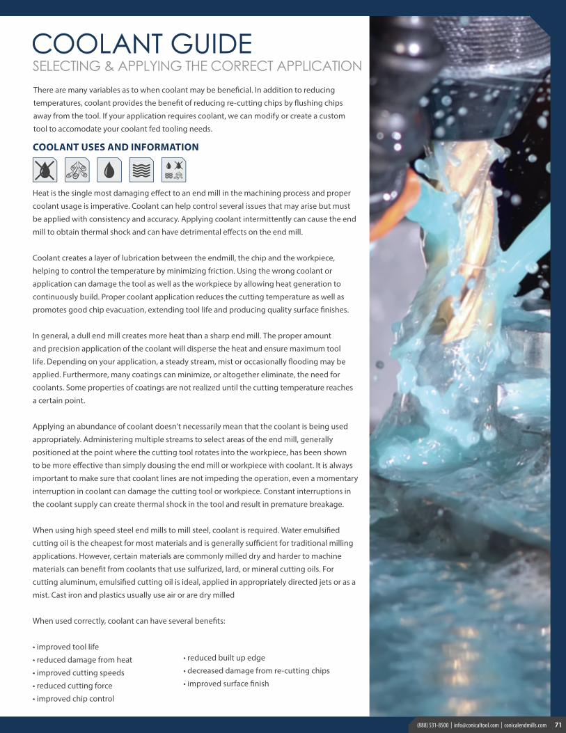
CONSIDER THE NUMBER OF FLUTES
To determine whether a two, three, four or greater flute end mill is
needed, several factors need to be considered. Two and three flute
end mills have better stock removal than multiple flute end mills but
a significantly decreased finish. End mills with five or more flutes are
ideal for finishing cuts and cuts in harder materials, but must operate
at lower material removal rates due to their poor chip evacuation
properties. When run at similar rates, multiple flute end mills will
take a lighter chip load per tooth, resulting in an improved finish
and smoother machining. Consider the type of cut needed to be
• Feeds and speeds• Rigidity needed• Preferred chip evacuation• Method of tool engagement• Depth of cut
• Desired finish• Helical angle• Workpiece hardness• Workpiece condition• Number of workpieces
performed, the chip space required based on the cut and material,
the production and metal removal rate needed and the desired
surface finish when selecting.
FLUTE CONSTRUCTION AND CONFIGURATIONHigher helix angles produce higher chip evacuation, thus the
capacity to increase speeds and feeds and decrease horsepower
requirements. Tool deflection is transferred vertically versus
horizontally which dampens vibrations, and increases speeds and
surface finish quality.
Traditionally, roughing operations or hard to machine materials
benefit from the improved flute strength of a lower helix end
mill. While using general purpose end mills, this may still hold
true, however newer high performance geometries take into
consideration flute and core strength, while adding the benefits of
a higher helix. Immediate edge build-up can occur with lower helix
end mills and create excessive chatter.
For an axial plunge cut, it is essential to use a center cutting tool.
Two flute end mills are center cutting, where multi-flute end mills
can vary. Multi-flute end mills create better surface finishes due to a
lighter chipload - per flute. Side loading is dramatically reduced with
lower helix angles, making it easier to mill thin walls.
ROUGHING END MILLSRoughing cuts are generally for preparing the surface before the
finishing cut. The purpose is to bring the diameter of the hole to a
“rough” size of the final cut. How this cut looks is of little importance.
Roughing cuts also allow for mistakes. Roughing cuts may consist of
several heavy cuts and the primary purpose is to clear material away,
in anticipation of the finishing cut.
FINISHING END MILLSA minimal amount of leftover material from the roughing cut is
removed with the finishing cut, machining the work to size in
addition to refining the surface of the workpiece.
SELECTING SUITABLE CHARACTERISTICS OF YOUR CUTTING TOOL The information on the following pages will help you to determine the proper tool for your specific application. Consider the material,
application and type of cut to identify the end mill you need. Note that the information provided is basic in nature and we can not account
for your particular machine, setup or application and there are many variables to consider. If you have any questions please do not hesitate
to contact us.
70 (888) 531-8500 | [email protected] | conicalendmills.com
71(888) 531-8500 | [email protected] | conicalendmills.com 717171(888) 531-8500 | [email protected] | conicalendmills.com
Heat is the single most damaging effect to an end mill in the machining process and proper
coolant usage is imperative. Coolant can help control several issues that may arise but must
be applied with consistency and accuracy. Applying coolant intermittently can cause the end
mill to obtain thermal shock and can have detrimental effects on the end mill.
Coolant creates a layer of lubrication between the endmill, the chip and the workpiece,
helping to control the temperature by minimizing friction. Using the wrong coolant or
application can damage the tool as well as the workpiece by allowing heat generation to
continuously build. Proper coolant application reduces the cutting temperature as well as
promotes good chip evacuation, extending tool life and producing quality surface finishes.
In general, a dull end mill creates more heat than a sharp end mill. The proper amount
and precision application of the coolant will disperse the heat and ensure maximum tool
life. Depending on your application, a steady stream, mist or occasionally flooding may be
applied. Furthermore, many coatings can minimize, or altogether eliminate, the need for
coolants. Some properties of coatings are not realized until the cutting temperature reaches
a certain point.
Applying an abundance of coolant doesn’t necessarily mean that the coolant is being used
appropriately. Administering multiple streams to select areas of the end mill, generally
positioned at the point where the cutting tool rotates into the workpiece, has been shown
to be more effective than simply dousing the end mill or workpiece with coolant. It is always
important to make sure that coolant lines are not impeding the operation, even a momentary
interruption in coolant can damage the cutting tool or workpiece. Constant interruptions in
the coolant supply can create thermal shock in the tool and result in premature breakage.
When using high speed steel end mills to mill steel, coolant is required. Water emulsified
cutting oil is the cheapest for most materials and is generally sufficient for traditional milling
applications. However, certain materials are commonly milled dry and harder to machine
materials can benefit from coolants that use sulfurized, lard, or mineral cutting oils. For
cutting aluminum, emulsified cutting oil is ideal, applied in appropriately directed jets or as a
mist. Cast iron and plastics usually use air or are dry milled
When used correctly, coolant can have several benefits:
• improved tool life
• reduced damage from heat
• improved cutting speeds
• reduced cutting force
• improved chip control
SELECTING & APPLYING THE CORRECT APPLICATION
• reduced built up edge
• decreased damage from re-cutting chips
• improved surface finish
COOLANT USES AND INFORMATION
There are many variables as to when coolant may be beneficial. In addition to reducing
temperatures, coolant provides the benefit of reducing re-cutting chips by flushing chips
away from the tool. If your application requires coolant, we can modify or create a custom
tool to accomodate your coolant fed tooling needs.
7171(888) 531-8500 | [email protected] | conicalendmills.com
(888) 531-8500 | [email protected] | conicalendmills.com7272 (888) 531-8500 | [email protected] | conicalendmills.com
SHANK VARIATIONS WE OFFER
SINGLE WELDON• allows for increased torque
• minimizes tool slippage and pull out
• provides a guide for proper tool projection length
DOUBLE WELDON• allows for increased torque
• minimizes tool slippage and pull out
• stabilizes large diameter tooling
FULL FLAT• for quick change tooling
• allows for varying degrees of projection
• same tool can be used at regular and extended lengths
REDUCED NECK• best for long reach/deep pocketing applications
• improved core rigidity with decreased flute length
• minimized tool deflection for high finish / tight tolerance machining
STRAIGHT SHANK• for use in shrink fit collets to minimize tool runout
• for high performance machining applications
• improved tool concentricity; generally found on carbide tooling
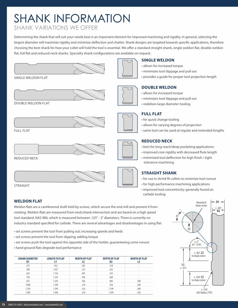
SHANK DIAMETERD1
LENGTH TO FLATL1
WIDTH OF FLATL2
DEPTH OF FLATD2
WIDTH OF FLAT L3
.375 .922 .281 .318 -
.500 1.057 .331 .433 -
.625 1.154 .401 .553 -
.750 1.243 .456 .668 -
.875 1.243 .456 .803 .5001.000 1.399 .516 .918 .5001.250 1.399 .516 1.149 .5001.500 1.446 .516 1.399 .562
WELDON FLAT Weldon flats are a cantilevered shaft held by screws, which secure the end mill and prevent it from
rotating. Weldon flats are measured from neck/shank intersection and are based on a high speed
tool standard, NAS 986, which is measured between .125” - 3” diameters. There is currently no
industry standard specified for carbide. There are several advantages and disadvantages in using flat:
• set screws prevent the tool from pulling out; increasing speeds and feeds
• set screws prevent the tool from slipping; adding torque
• set screws push the tool against the opposite side of the holder, guaranteeing some runout
• hand ground flats degrade tool performance
Determining the shank that will suit your needs best is an important element for improved machining and rigidity. In general, selecting the
largest diameter will maximize rigidity and minimize deflection and chatter. Shank designs are targeted towards specific applications, therefore
choosing the best shank for how your collet will hold the tool is essential. We offer a standard straight shank, single weldon flat, double weldon
flat, full flat and reduced neck shanks. Specialty shank configurations are available on request.
72 (888) 531-8500 | [email protected] | conicalendmills.com
73(888) 531-8500 | [email protected] | conicalendmills.com 737373(888) 531-8500 | [email protected] | conicalendmills.com
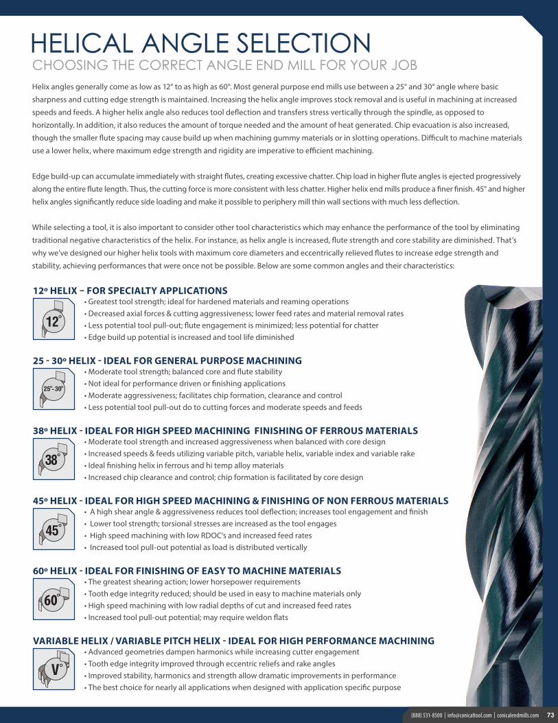
CHOOSING THE CORRECT ANGLE END MILL FOR YOUR JOBHelix angles generally come as low as 12° to as high as 60°. Most general purpose end mills use between a 25° and 30° angle where basic
sharpness and cutting edge strength is maintained. Increasing the helix angle improves stock removal and is useful in machining at increased
speeds and feeds. A higher helix angle also reduces tool deflection and transfers stress vertically through the spindle, as opposed to
horizontally. In addition, it also reduces the amount of torque needed and the amount of heat generated. Chip evacuation is also increased,
though the smaller flute spacing may cause build up when machining gummy materials or in slotting operations. Difficult to machine materials
use a lower helix, where maximum edge strength and rigidity are imperative to efficient machining.
Edge build-up can accumulate immediately with straight flutes, creating excessive chatter. Chip load in higher flute angles is ejected progressively
along the entire flute length. Thus, the cutting force is more consistent with less chatter. Higher helix end mills produce a finer finish. 45° and higher
helix angles significantly reduce side loading and make it possible to periphery mill thin wall sections with much less deflection.
While selecting a tool, it is also important to consider other tool characteristics which may enhance the performance of the tool by eliminating
traditional negative characteristics of the helix. For instance, as helix angle is increased, flute strength and core stability are diminished. That’s
why we’ve designed our higher helix tools with maximum core diameters and eccentrically relieved flutes to increase edge strength and
stability, achieving performances that were once not be possible. Below are some common angles and their characteristics:
45º HELIX - IDEAL FOR HIGH SPEED MACHINING & FINISHING OF NON FERROUS MATERIALS• A high shear angle & aggressiveness reduces tool deflection; increases tool engagement and finish• Lower tool strength; torsional stresses are increased as the tool engages• High speed machining with low RDOC’s and increased feed rates• Increased tool pull-out potential as load is distributed vertically
60º HELIX - IDEAL FOR FINISHING OF EASY TO MACHINE MATERIALS• The greatest shearing action; lower horsepower requirements• Tooth edge integrity reduced; should be used in easy to machine materials only• High speed machining with low radial depths of cut and increased feed rates• Increased tool pull-out potential; may require weldon flats
VARIABLE HELIX / VARIABLE PITCH HELIX - IDEAL FOR HIGH PERFORMANCE MACHINING• Advanced geometries dampen harmonics while increasing cutter engagement• Tooth edge integrity improved through eccentric reliefs and rake angles• Improved stability, harmonics and strength allow dramatic improvements in performance• The best choice for nearly all applications when designed with application specific purpose
V°
12º HELIX – FOR SPECIALTY APPLICATIONS• Greatest tool strength; ideal for hardened materials and reaming operations• Decreased axial forces & cutting aggressiveness; lower feed rates and material removal rates• Less potential tool pull-out; flute engagement is minimized; less potential for chatter• Edge build up potential is increased and tool life diminished
38º HELIX - IDEAL FOR HIGH SPEED MACHINING FINISHING OF FERROUS MATERIALS• Moderate tool strength and increased aggressiveness when balanced with core design• Increased speeds & feeds utilizing variable pitch, variable helix, variable index and variable rake• Ideal finishing helix in ferrous and hi temp alloy materials• Increased chip clearance and control; chip formation is facilitated by core design
25 - 30º HELIX - IDEAL FOR GENERAL PURPOSE MACHINING• Moderate tool strength; balanced core and flute stability• Not ideal for performance driven or finishing applications• Moderate aggressiveness; facilitates chip formation, clearance and control• Less potential tool pull-out do to cutting forces and moderate speeds and feeds
7373(888) 531-8500 | [email protected] | conicalendmills.com
(888) 531-8500 | [email protected] | conicalendmills.com7474 (888) 531-8500 | [email protected] | conicalendmills.com
FLUTE
FLUTE
TOOL FEATURES
TIP SHANK
Single Weldon Double Weldon
see pg. 76 for more information
see pg. 72 for more information
Whistle Notch Stub (S) Regular (R) Long (L) Extra Long (X) Reached Neck (N)
(R) (N)(X)
MATERIALS & COATINGS
see pgs. 44-57 for more information
Aluminum Chromium Nitride nano
Titanium Aluminum Nitride
Titanium Nitride Titanium Carbonitride
Aluminum Titanium Nitride
Amorphous & CVD Diamond
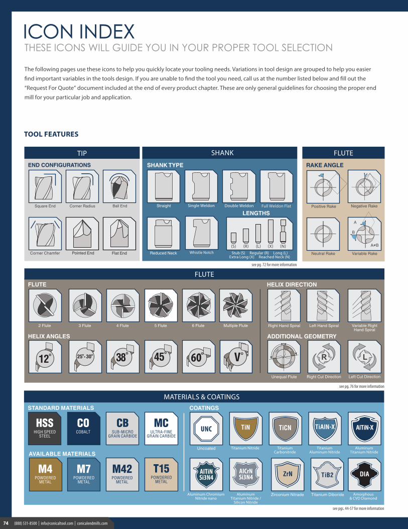
THESE ICONS WILL GUIDE YOU IN YOUR PROPER TOOL SELECTION
The following pages use these icons to help you quickly locate your tooling needs. Variations in tool design are grouped to help you easier
find important variables in the tools design. If you are unable to find the tool you need, call us at the number listed below and fill out the
“Request For Quote” document included at the end of every product chapter. These are only general guidelines for choosing the proper end
mill for your particular job and application.
V°
Pointed End Flat End
Aluminum Titanium Nitride /
Silicon Nitride
75(888) 531-8500 | [email protected] | conicalendmills.com 757575(888) 531-8500 | [email protected] | conicalendmills.com
INDUSTRIES
PROCESSES
For information on processes and applications, please
see our technical information guide on pages 41 - 67.
FIN
ISHI
NG
SPEC
IALT
Y
ENTR
Y
see pages 48-64 for more information
see pg. 45 for more information
WORKPIECE MATERIALS
STCARBONSTEEL
LOW CARBON
STCARBONSTEEL
MEDIUM CARBON
TSTOOL STEEL 38 HRc
TSTOOL STEEL
39-48 HRc
HSHARDENED
STEEL48-87 HRc
HSHARDENED
STEEL58-65 HRc
SSSTAINLESS
STEELEASY
SSSTAINLESS
STEELDIFFICULT
SSSTAINLESS
STEELMODERATE
CICAST IRONGRAY
CICAST IRON
MALLEABLE
TITITANIUM ALLOYS25-36 HRc
CICAST IRON
DUCTILE
HIHI-TEMP ALLOYS 30-52 HRc
ALUMINUM ALLOYS
Low Si (<10%)
ALALUMINUM
ALLOYSHigh Si (>10%
AL)
ALUMINUMALLOYS
MGCOPPER ALLOYS
39 - 48 HRc
CACARBON & GRAPHITE48 - 57 HRc
CGPLASTICS &
COMPOSITES28 - 57 HRc
PL
MA
TERI
AL
REM
OVA
L
Conventional Milling Climb Milling
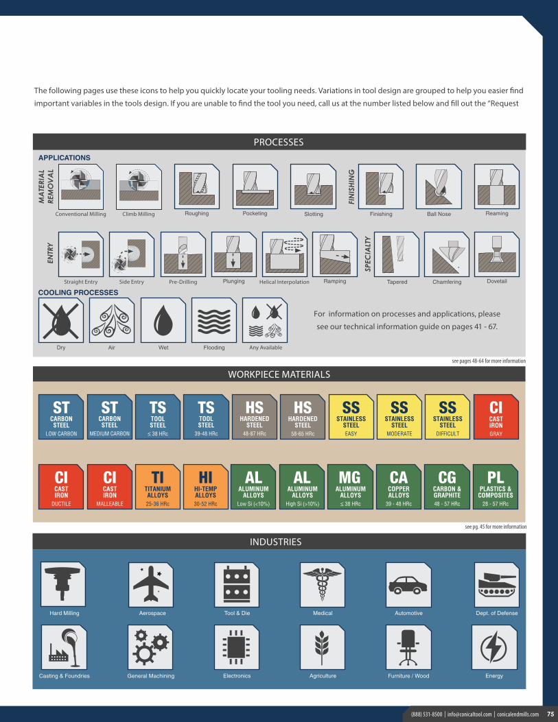
The following pages use these icons to help you quickly locate your tooling needs. Variations in tool design are grouped to help you easier find
important variables in the tools design. If you are unable to find the tool you need, call us at the number listed below and fill out the “Request