Embed Size (px)
Citation preview
Vacu-Break®Fusible Panel UnitsSelection and Application Guide
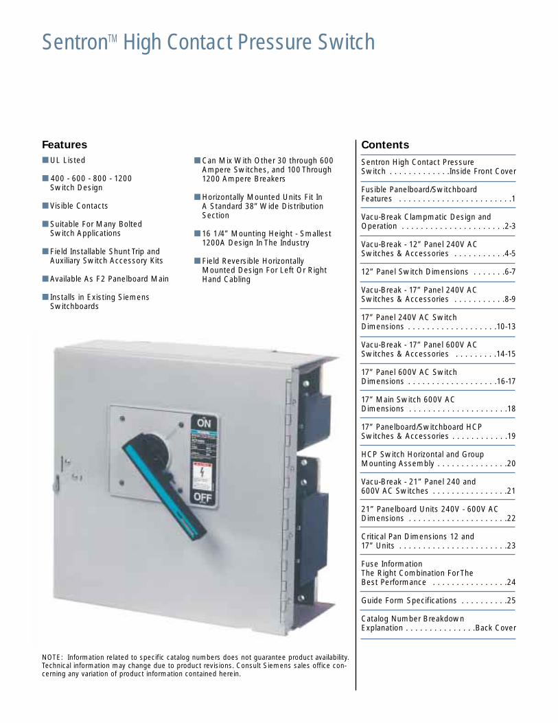
SentronTM High Contact Pressure Switch
Features■ UL Listed
■ 400 - 600 - 800 - 1200 Switch Design
■ Visible Contacts
■ Suitable For Many Bolted Switch Applications
■ Field Installable Shunt Trip and Auxiliary Switch Accessory Kits
■ Available As F2 Panelboard Main
■ Installs in Existing Siemens Switchboards
Contents
Sentron High Contact PressureSwitch . . . . . . . . . . . . .Inside Front Cover
Fusible Panelboard/SwitchboardFeatures . . . . . . . . . . . . . . . . . . . . . . . .1
Vacu-Break Clampmatic Design andOperation . . . . . . . . . . . . . . . . . . . . . .2-3
Vacu-Break - 12” Panel 240V ACSwitches & Accessories . . . . . . . . . . .4-5
12” Panel Switch Dimensions . . . . . . .6-7
Vacu-Break - 17” Panel 240V ACSwitches & Accessories . . . . . . . . . . .8-9
17” Panel 240V AC SwitchDimensions . . . . . . . . . . . . . . . . . . .10-13
Vacu-Break - 17” Panel 600V ACSwitches & Accessories . . . . . . . . .14-15
17” Panel 600V AC Switch Dimensions . . . . . . . . . . . . . . . . . . .16-17
17” Main Switch 600V ACDimensions . . . . . . . . . . . . . . . . . . . . .18
17” Panelboard/Switchboard HCPSwitches & Accessories . . . . . . . . . . . .19
HCP Switch Horizontal and GroupMounting Assembly . . . . . . . . . . . . . . .20
Vacu-Break - 21” Panel 240 and 600V AC Switches . . . . . . . . . . . . . . . .21
21” Panelboard Units 240V - 600V ACDimensions . . . . . . . . . . . . . . . . . . . . .22
Critical Pan Dimensions 12 and17” Units . . . . . . . . . . . . . . . . . . . . . . .23
Fuse Information The Right Combination ForThe Best Performance . . . . . . . . . . . . . . . .24
Guide Form Specifications . . . . . . . . . .25
Catalog Number BreakdownExplanation . . . . . . . . . . . . . . .Back Cover
■ Can Mix With Other 30 through 600Ampere Switches, and 100 Through1200 Ampere Breakers
■ Horizontally Mounted Units Fit In A Standard 38”Wide Distribution Section
■ 16 1/4” Mounting Height - Smallest 1200A Design In The Industry
■ Field Reversible Horizontally Mounted Design For Left Or Right Hand Cabling
NOTE: Information related to specific catalog numbers does not guarantee product availability.Technical information may change due to product revisions. Consult Siemens sales office con-cerning any variation of product information contained herein.
Fusible Panelboard and Switchboard Switch Features
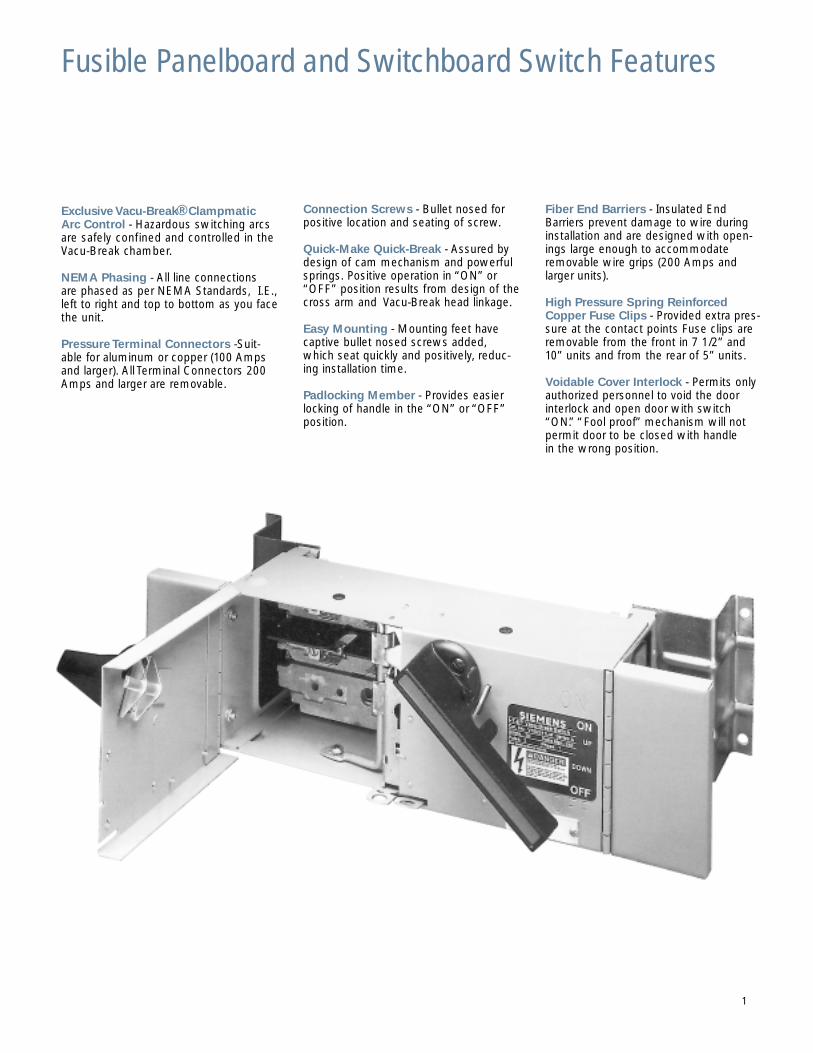
Exclusive Vacu-Break®ClampmaticArc Control - Hazardous switching arcsare safely confined and controlled in theVacu-Break chamber.
NEMA Phasing - All line connections are phased as per NEMA Standards, I.E.,left to right and top to bottom as you facethe unit.
Pressure Terminal Connectors -Suit-able for aluminum or copper (100 Ampsand larger). All Terminal Connectors 200Amps and larger are removable.
Connection Screws - Bullet nosed forpositive location and seating of screw.
Quick-Make Quick-Break - Assured bydesign of cam mechanism and powerfulsprings. Positive operation in “ON” or“OFF” position results from design of thecross arm and Vacu-Break head linkage.
Easy Mounting - Mounting feet havecaptive bullet nosed screws added,which seat quickly and positively, reduc-ing installation time.
Padlocking Member - Provides easierlocking of handle in the “ON” or “OFF”position.
Fiber End Barriers - Insulated EndBarriers prevent damage to wire duringinstallation and are designed with open-ings large enough to accommodateremovable wire grips (200 Amps andlarger units).
High Pressure Spring ReinforcedCopper Fuse Clips - Provided extra pres-sure at the contact points Fuse clips areremovable from the front in 7 1/2” and10” units and from the rear of 5” units.
Voidable Cover Interlock - Permits onlyauthorized personnel to void the doorinterlock and open door with switch“ON.”“Fool proof” mechanism will notpermit door to be closed with handle in the wrong position.
1
Vacu-Break Clampmatic® Design and Operation
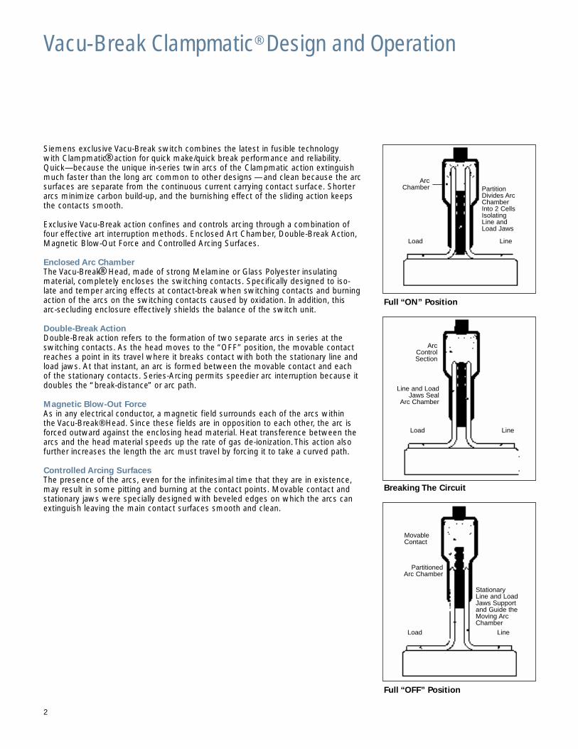
Siemens exclusive Vacu-Break switch combines the latest in fusible technology with Clampmatic®action for quick make/quick break performance and reliability.Quick—because the unique in-series twin arcs of the Clampmatic action extinguishmuch faster than the long arc common to other designs —and clean because the arcsurfaces are separate from the continuous current carrying contact surface. Shorterarcs minimize carbon build-up, and the burnishing effect of the sliding action keepsthe contacts smooth.
Exclusive Vacu-Break action confines and controls arcing through a combination offour effective art interruption methods. Enclosed Art Chamber, Double-Break Action,Magnetic Blow-Out Force and Controlled Arcing Surfaces.
Enclosed Arc ChamberThe Vacu-Break® Head, made of strong Melamine or Glass Polyester insulating material, completely encloses the switching contacts. Specifically designed to iso-late and temper arcing effects at contact-break when switching contacts and burningaction of the arcs on the switching contacts caused by oxidation. In addition, this arc-secluding enclosure effectively shields the balance of the switch unit.
Double-Break ActionDouble-Break action refers to the formation of two separate arcs in series at theswitching contacts. As the head moves to the “OFF” position, the movable contactreaches a point in its travel where it breaks contact with both the stationary line andload jaws. At that instant, an arc is formed between the movable contact and each of the stationary contacts. Series-Arcing permits speedier arc interruption because itdoubles the “break-distance” or arc path.
Magnetic Blow-Out ForceAs in any electrical conductor, a magnetic field surrounds each of the arcs within the Vacu-Break®Head. Since these fields are in opposition to each other, the arc isforced outward against the enclosing head material. Heat transference between thearcs and the head material speeds up the rate of gas de-ionization.This action alsofurther increases the length the arc must travel by forcing it to take a curved path.
Controlled Arcing SurfacesThe presence of the arcs, even for the infinitesimal time that they are in existence,may result in some pitting and burning at the contact points. Movable contact andstationary jaws were specially designed with beveled edges on which the arcs canextinguish leaving the main contact surfaces smooth and clean.
Full “ON” Position
Breaking The Circuit
Full “OFF” Position
2
StationaryLine and LoadJaws Supportand Guide theMoving ArcChamber
MovableContact
PartitionedArc Chamber
Load Line
Load Line
Arc ControlSection
Line and LoadJaws Seal
Arc Chamber
Load Line
Arc Chamber Partition
Divides ArcChamberInto 2 CellsIsolatingLine andLoad Jaws
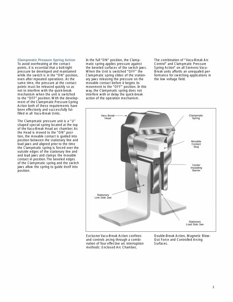
Clampmatic Pressure Spring ActionTo avoid overheating at the contactpoints, it is essential that a bolt-tightpressure be developed and maintainedwhile the switch is in the “ON” position,even after repeated operations. At thesame time, the pressure at the contactpoints must be released quickly so asnot to interfere with the quick-breakmechanism when the unit is switchedto the “OFF” position. With the develop-ment of the Clampmatic Pressure SpringAction both of these requirements havebeen effectively and successfully ful-filled in all Vacu-Break Units.
The Clampmatic pressure unit is a “U”shaped special spring located at the topof the Vacu-Break Head arc chamber. Asthe Head is moved to the “ON” posi-tion, the movable contact is guided intoposition between the stationary line andload jaws and aligned prior to the timethe Clampmatic spring is forced over the outside edges of the stationary line andand load jaws and clamps the movablecontact in position.The beveled edges of the Clampmatic spring and the switchjaws allow the spring to guide itself intoposition.
In the full “ON” position, the Clamp-matic spring applies pressure againstthe beveled surfaces of the switch jaws.When the Unit is switched “OFF” theClampmatic spring slides of the station-ary jaws releasing the pressure on themovable contact before it begins itsmovement to the “OFF” position. In thisway, the Clampmatic spring does notinterfere with or delay the quick-breakaction of the operation mechanism.
The combination of “Vacu-Break ArcControl” and Clampmatic PressureSpring Action” on all Siemens Vacu-Break units affords an unequaled per-formance for switching applications inthe low voltage field.
3
Exclusive Vacu-Break Action confinesand controls arcing through a combi-nation of four effective arc interruptionmethods: Enclosed Arc Chamber,
Double-Break Action, Magnetic Blow-Out Force and Controlled ArcingSurfaces.
Vacu BreakHead
Clampmatic Spring
MovableContact
Slug
CenterInsulating
Barrier
StationaryLoad Side Jaw
StationaryLine Side Jaw
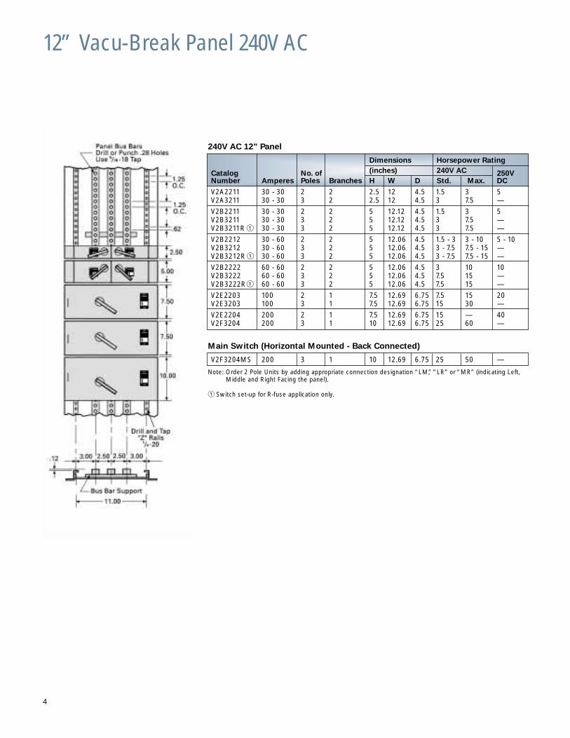
12” Vacu-Break Panel 240V AC
240V AC 12” Panel
Main Switch (Horizontal Mounted - Back Connected)
V2F3204MS 200 3 1 10 12.69 6.75 25 50 —
Note: Order 2 Pole Units by adding appropriate connection designation “LM,” “LR” or “MR” (indicating Left,Middle and Right Facing the panel).
� Switch set-up for R-fuse application only.
4
Dimensions Horsepower Rating
Catalog No. of (inches) 240V AC 250VNumber Amperes Poles Branches H W D Std. Max. DC
V2A2211 30 - 30 2 2 2.5 12 4.5 1.5 3 5V2A3211 30 - 30 3 2 2.5 12 4.5 3 7.5 —
V2B2211 30 - 30 2 2 5 12.12 4.5 1.5 3 5V2B3211 30 - 30 3 2 5 12.12 4.5 3 7.5 —V2B3211R � 30 - 30 3 2 5 12.12 4.5 3 7.5 —
V2B2212 30 - 60 2 2 5 12.06 4.5 1.5 - 3 3 - 10 5 - 10V2B3212 30 - 60 3 2 5 12.06 4.5 3 - 7.5 7.5 - 15 —V2B3212R � 30 - 60 3 2 5 12.06 4.5 3 - 7.5 7.5 - 15 —
V2B2222 60 - 60 2 2 5 12.06 4.5 3 10 10V2B3222 60 - 60 3 2 5 12.06 4.5 7.5 15 —V2B3222R� 60 - 60 3 2 5 12.06 4.5 7.5 15 —
V2E2203 100 2 1 7.5 12.69 6.75 7.5 15 20V2E3203 100 3 1 7.5 12.69 6.75 15 30 —
V2E2204 200 2 1 7.5 12.69 6.75 15 — 40V2F3204 200 3 1 10 12.69 6.75 25 60 —
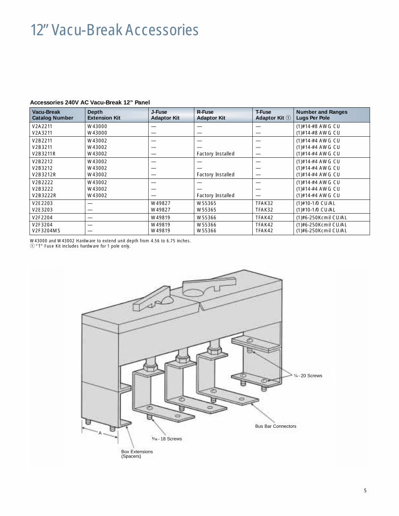
12” Vacu-Break Accessories
Accessories 240V AC Vacu-Break 12” Panel
W43000 and W43002 Hardware to extend unit depth from 4.56 to 6.75 inches.� “T” Fuse Kit includes hardware for 1 pole only.
5
¹⁄₄ - 20 Screws
Bus Bar Connectors
⁵⁄₁₆ - 18 Screws
Box Extensions(Spacers)
A
Vacu-Break Depth J-Fuse R-Fuse T-Fuse Number and RangesCatalog Number Extension Kit Adaptor Kit Adaptor Kit Adaptor Kit � Lugs Per Pole
V2A2211 W43000 — — — (1)#14-#8 AWG CUV2A3211 W43000 — — — (1)#14-#8 AWG CU
V2B2211 W43002 — — — (1)#14-#4 AWG CUV2B3211 W43002 — — — (1)#14-#4 AWG CUV2B3211R W43002 — Factory Installed — (1)#14-#4 AWG CU
V2B2212 W43002 — — — (1)#14-#4 AWG CUV2B3212 W43002 — — — (1)#14-#4 AWG CUV2B3212R W43002 — Factory Installed — (1)#14-#4 AWG CU
V2B2222 W43002 — — — (1)#14-#4 AWG CUV2B3222 W43002 — — — (1)#14-#4 AWG CUV2B3222R W43002 — Factory Installed — (1)#14-#4 AWG CU
V2E2203 — W49827 W55365 TFAK32 (1)#10-1/0 CU/ALV2E3203 — W49827 W55365 TFAK32 (1)#10-1/0 CU/AL
V2F2204 — W49819 W55366 TFAK42 (1)#6-250Kcmil CU/ALV2F3204 — W49819 W55366 TFAK42 (1)#6-250Kcmil CU/ALV2F3204MS — W49819 W55366 TFAK42 (1)#6-250Kcmil CU/AL
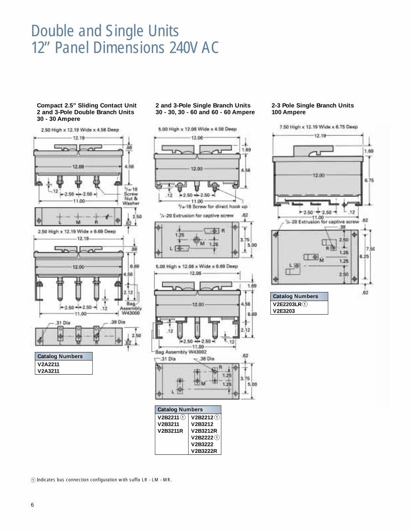
Double and Single Units12” Panel Dimensions 240V AC
� Indicates bus connection configuration with suffix LR - LM - MR.
2-3 Pole Single Branch Units100 Ampere
6
Catalog Numbers
V2B2211 � V2B2212 �V2B3211 V2B3212V2B3211R V2B3212R
V2B2222 �V2B3222V2B3222R
Catalog Numbers
V2E2203LR �V2E3203
Catalog Numbers
V2A2211V2A3211
Compact 2.5” Sliding Contact Unit2 and 3-Pole Double Branch Units30 - 30 Ampere
2 and 3-Pole Single Branch Units30 - 30, 30 - 60 and 60 - 60 Ampere
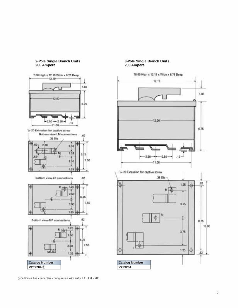
2-Pole Single Branch Units200 Ampere
3-Pole Single Branch Units200 Ampere
7
� Indicates bus connection configuration with suffix LR - LM - MR.
Catalog Number
V2E2204 �Catalog Number
V2F3204
17” Vacu-Break Panel 240V AC
240V AC 17” Panel
Main Switch (Horizontal Mounted - Back Connected)
V7E3203MS 100 3 1 7.5 17.69 6.75 15 30V7E2204MS � 200 2 1 7.5 17.69 6.75 15 —V7F3204MS 200 3 1 10 17.69 6.75 25 60V7H2205MS � 400 2 1 15 17.69 10.5 — —V7H3205MS 400 3 1 15 17.69 10.5 50 125V7H2206MS � 600 2 1 15 17.69 10.5 — —V7H3206MS 600 3 1 15 17.69 10.5 50 125
Main Switch (Vertical Mounted Top Feed)VMS325T 400 3 1 18.75 17.19 10.37VMS326T 200 3 1 18.75 17.19 10.37
Main Switch (Vertical Mounted Bottom Feed)VMS325B 400 3 1 18.75 17.19 10.37VMS326B 200 3 1 18.75 17.19 10.37
Note: Order 2 Pole Units by adding appropriate connection designation “LM,” “LR” or “MR” (indicating Left,Middle and Right, Facing the panel).
� This unit is not a Vacu-Break unit, but rather operates on a sliding contact design. Rated 10,000 AIC max.with Class H or R fuses. Will not accept Class R fuse clip kits.
� Switch set-up for R-fuse application only.� Rated 600V AC but factory configured to accepted 250V Class H, K or R fuses. Convertible for Class J
fuses.� Available as Type LR connection designation only.
8
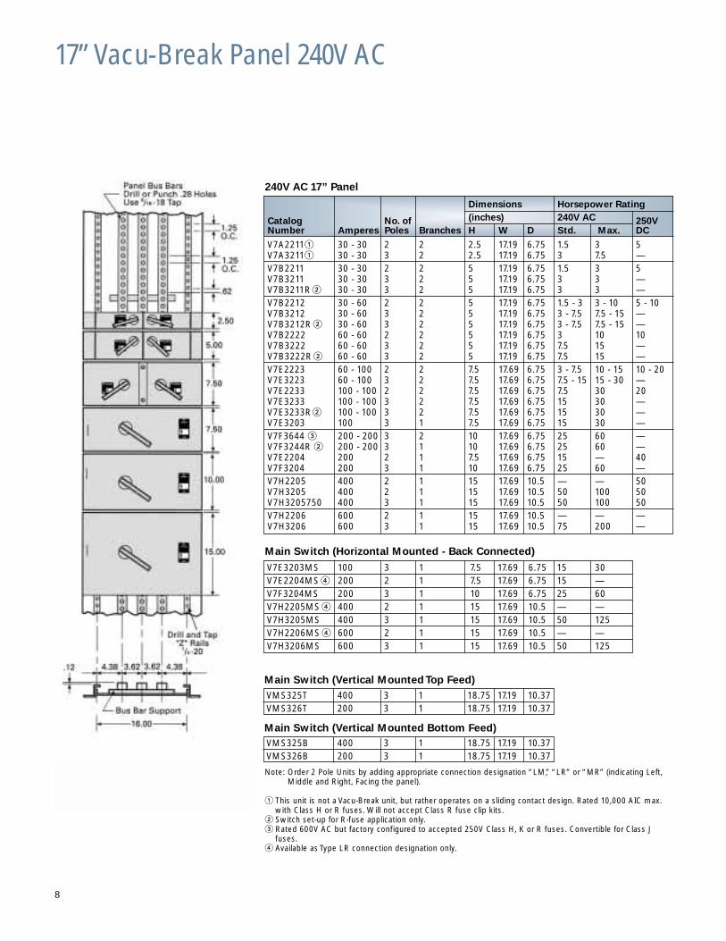
Dimensions Horsepower Rating
Catalog No. of (inches) 240V AC 250VNumber Amperes Poles Branches H W D Std. Max. DC
V7A2211� 30 - 30 2 2 2.5 17.19 6.75 1.5 3 5V7A3211� 30 - 30 3 2 2.5 17.19 6.75 3 7.5 —V7B2211 30 - 30 2 2 5 17.19 6.75 1.5 3 5V7B3211 30 - 30 3 2 5 17.19 6.75 3 3 —V7B3211R � 30 - 30 3 2 5 17.19 6.75 3 3 —V7B2212 30 - 60 2 2 5 17.19 6.75 1.5 - 3 3 - 10 5 - 10V7B3212 30 - 60 3 2 5 17.19 6.75 3 - 7.5 7.5 - 15 —V7B3212R � 30 - 60 3 2 5 17.19 6.75 3 - 7.5 7.5 - 15 —V7B2222 60 - 60 2 2 5 17.19 6.75 3 10 10V7B3222 60 - 60 3 2 5 17.19 6.75 7.5 15 —V7B3222R � 60 - 60 3 2 5 17.19 6.75 7.5 15 —V7E2223 60 - 100 2 2 7.5 17.69 6.75 3 - 7.5 10 - 15 10 - 20V7E3223 60 - 100 3 2 7.5 17.69 6.75 7.5 - 15 15 - 30 —V7E2233 100 - 100 2 2 7.5 17.69 6.75 7.5 30 20V7E3233 100 - 100 3 2 7.5 17.69 6.75 15 30 —V7E3233R� 100 - 100 3 2 7.5 17.69 6.75 15 30 —V7E3203 100 3 1 7.5 17.69 6.75 15 30 —V7F3644 � 200 - 200 3 2 10 17.69 6.75 25 60 —V7F3244R � 200 - 200 3 1 10 17.69 6.75 25 60 —V7E2204 200 2 1 7.5 17.69 6.75 15 — 40V7F3204 200 3 1 10 17.69 6.75 25 60 —V7H2205 400 2 1 15 17.69 10.5 — — 50V7H3205 400 2 1 15 17.69 10.5 50 100 50V7H3205750 400 3 1 15 17.69 10.5 50 100 50V7H2206 600 2 1 15 17.69 10.5 — — —V7H3206 600 3 1 15 17.69 10.5 75 200 —
17” Vacu-Break Accessories
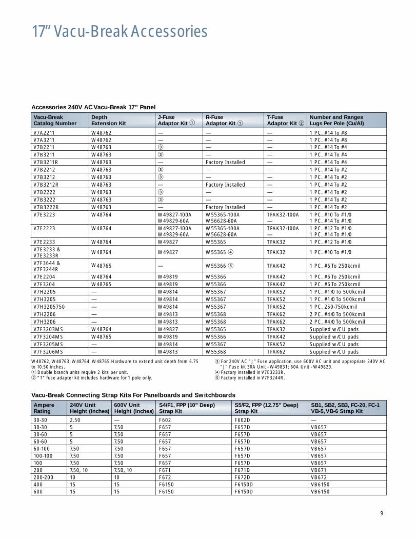
Accessories 240V AC Vacu-Break 17” Panel
W48762, W48763, W48764, W48765 Hardware to extend unit depth from 6.75to 10.50 inches.� Double branch units require 2 kits per unit.� “T” fuse adapter kit includes hardware for 1 pole only.
� For 240V AC “J” Fuse application, use 600V AC unit and appropriate 240V AC “J” Fuse kit 30A Unit - W49831; 60A Unit - W49829.
� Factory installed in V7E3233R.� Factory installed in V7F3244R.
Vacu-Break Connecting Strap Kits For Panelboards and Switchboards
Vacu-Break Depth J-Fuse R-Fuse T-Fuse Number and RangesCatalog Number Extension Kit Adaptor Kit � Adaptor Kit � Adaptor Kit � Lugs Per Pole (Cu/Al)
V7A2211 W48762 — — — 1 PC. #14 To #8V7A3211 W48762 — — — 1 PC. #14 To #8V7B2211 W48763 � — — 1 PC. #14 To #4V7B3211 W48763 � — — 1 PC. #14 To #4V7B3211R W48763 — Factory Installed — 1 PC. #14 To #4V7B2212 W48763 � — — 1 PC. #14 To #2V7B3212 W48763 � — — 1 PC. #14 To #2V7B3212R W48763 — Factory Installed — 1 PC. #14 To #2V7B2222 W48763 � — — 1 PC. #14 To #2V7B3222 W48763 � — — 1 PC. #14 To #2V7B3222R W48763 — Factory Installed — 1 PC. #14 To #2V7E3223 W48764 W49827-100A W55365-100A TFAK32-100A 1 PC. #10 To #1/0
W49829-60A W56628-60A — 1 PC. #14 To #1/0V7E2223 W48764 W49827-100A W55365-100A TFAK32-100A 1 PC. #12 To #1/0
W49829-60A W56628-60A — 1 PC. #14 To #1/0V7E2233 W48764 W49827 W55365 TFAK32 1 PC. #12 To #1/0V7E3233 & W48764 W49827 W55365 � TFAK32 1 PC. #10 To #1/0V7E3233RV7F3644 & W48765 — W55366 � TFAK42 1 PC. #6 To 250kcmilV7F3244RV7E2204 W48764 W49819 W55366 TFAK42 1 PC. #6 To 250kcmilV7F3204 W48765 W49819 W55366 TFAK42 1 PC. #6 To 250kcmilV7H2205 — W49814 W55367 TFAK52 1 PC. #1/0 To 500kcmilV7H3205 — W49814 W55367 TFAK52 1 PC. #1/0 To 500kcmilV7H3205750 — W49814 W55367 TFAK52 1 PC. 250-750kcmilV7H2206 — W49813 W55368 TFAK62 2 PC. #4/0 To 500kcmilV7H3206 — W49813 W55368 TFAK62 2 PC. #4/0 To 500kcmilV7F3203MS W48764 W49827 W55365 TFAK32 Supplied w/CU padsV7F3204MS W48765 W49819 W55366 TFAK42 Supplied w/CU padsV7F3205MS — W49814 W55367 TFAK52 Supplied w/CU padsV7F3206MS — W49813 W55368 TFAK62 Supplied w/CU pads
Ampere 240V Unit 600V Unit S4/F1, FPP (10” Deep) S5/F2, FPP (12.75” Deep) SB1, SB2, SB3, FC-20, FC-1Rating Height (Inches) Height (Inches) Strap Kit Strap Kit VB-5,VB-6 Strap Kit
30-30 2.50 — F602 F602D —30-30 5 7.50 F657 F657D VB65730-60 5 7.50 F657 F657D VB65760-60 5 7.50 F657 F657D VB65760-100 7.50 7.50 F657 F657D VB657100-100 7.50 7.50 F657 F657D VB657100 7.50 7.50 F657 F657D VB657200 7.50, 10 7.50, 10 F671 F671D VB671200-200 10 10 F672 F672D VB672400 15 15 F6150 F6150D VB6150600 15 15 F6150 F6150D VB6150
9
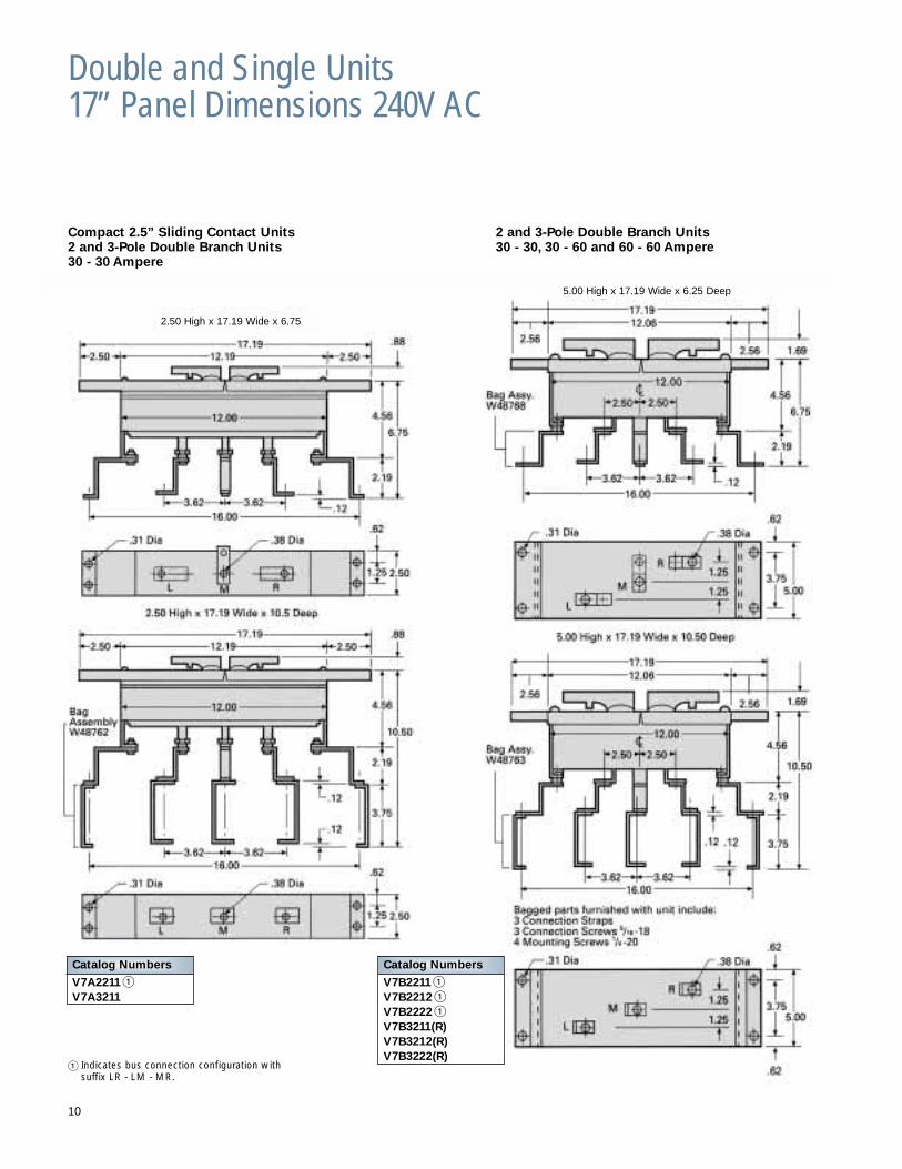
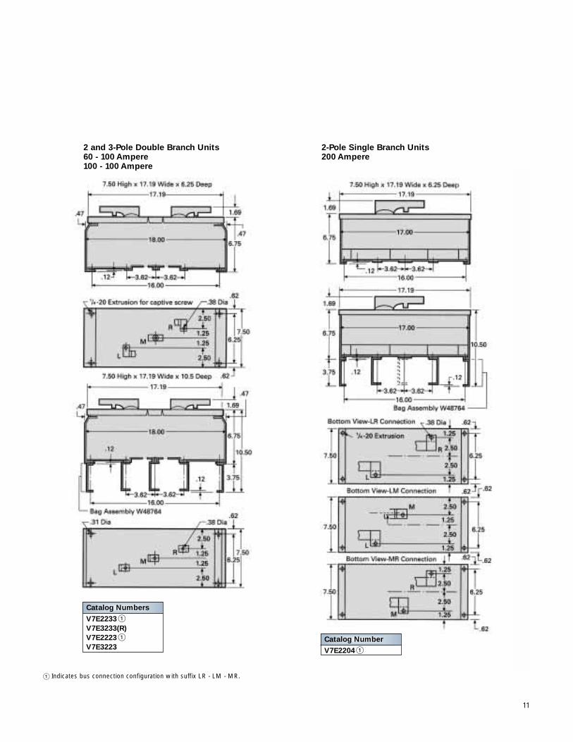
Double and Single Units17” Panel Dimensions 240V AC
2 and 3-Pole Double Branch Units30 - 30, 30 - 60 and 60 - 60 Ampere
10
Compact 2.5” Sliding Contact Units2 and 3-Pole Double Branch Units30 - 30 Ampere
2.50 High x 17.19 Wide x 6.75
5.00 High x 17.19 Wide x 6.25 Deep
Catalog Numbers
V7A2211 �V7A3211
� Indicates bus connection configuration with suffix LR - LM - MR.
Catalog Numbers
V7B2211 �V7B2212 �V7B2222 �V7B3211(R)V7B3212(R)V7B3222(R)
11
Catalog Number
V7E2204 �
Catalog Numbers
V7E2233 �V7E3233(R)V7E2223 �V7E3223
� Indicates bus connection configuration with suffix LR - LM - MR.
2 and 3-Pole Double Branch Units60 - 100 Ampere100 - 100 Ampere
2-Pole Single Branch Units200 Ampere
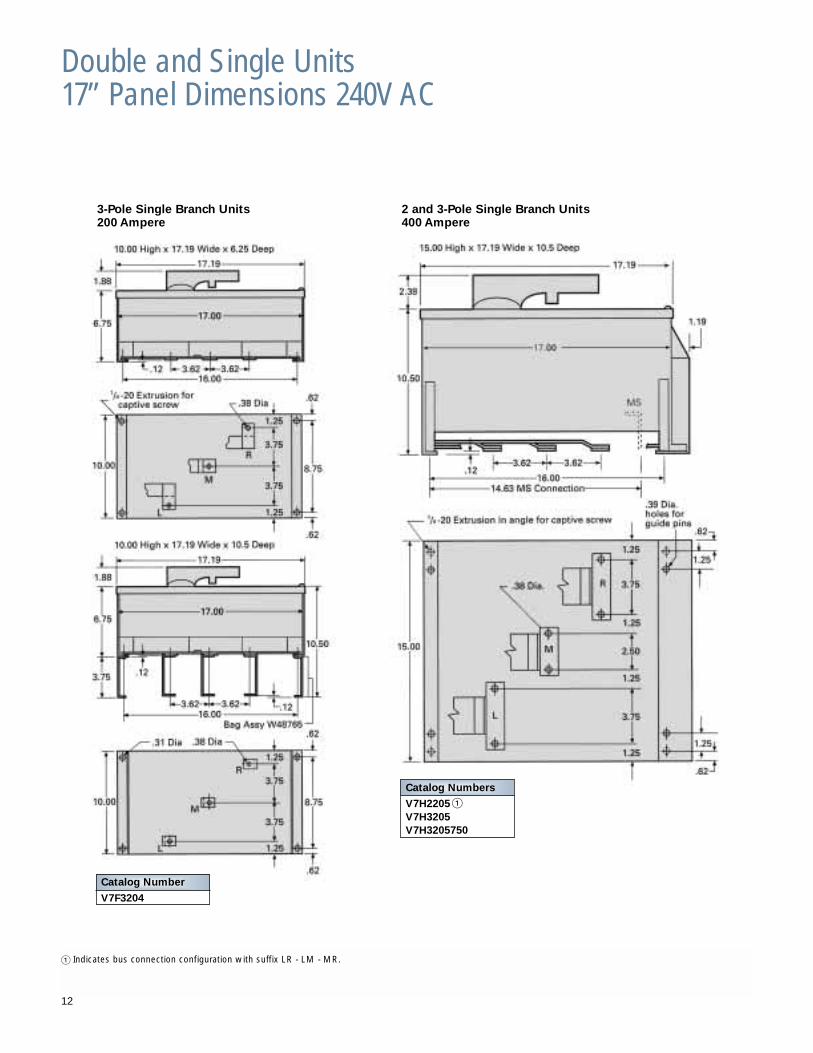
Double and Single Units17” Panel Dimensions 240V AC
� Indicates bus connection configuration with suffix LR - LM - MR.
Catalog Numbers
V7H2205 �V7H3205V7H3205750
Catalog Number
V7F3204
3-Pole Single Branch Units200 Ampere
2 and 3-Pole Single Branch Units400 Ampere
12
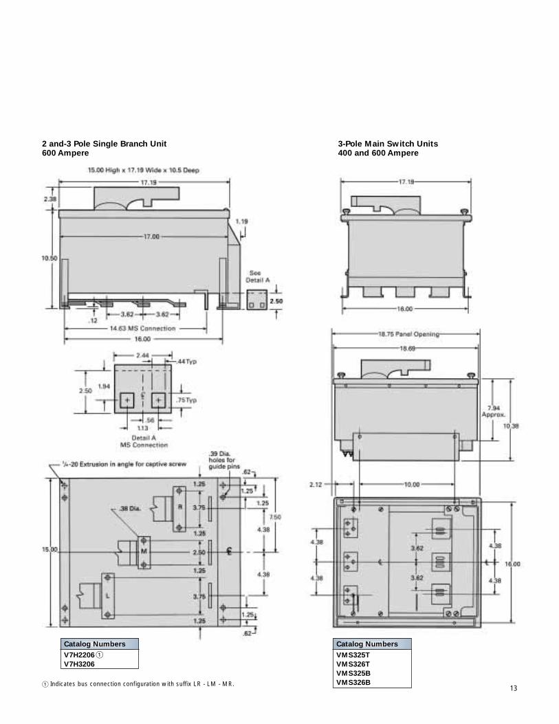
2 and-3 Pole Single Branch Unit600 Ampere
3-Pole Main Switch Units400 and 600 Ampere
Catalog Numbers
V7H2206 �V7H3206
� Indicates bus connection configuration with suffix LR - LM - MR.
Catalog Numbers
VMS325TVMS326TVMS325BVMS326B
13
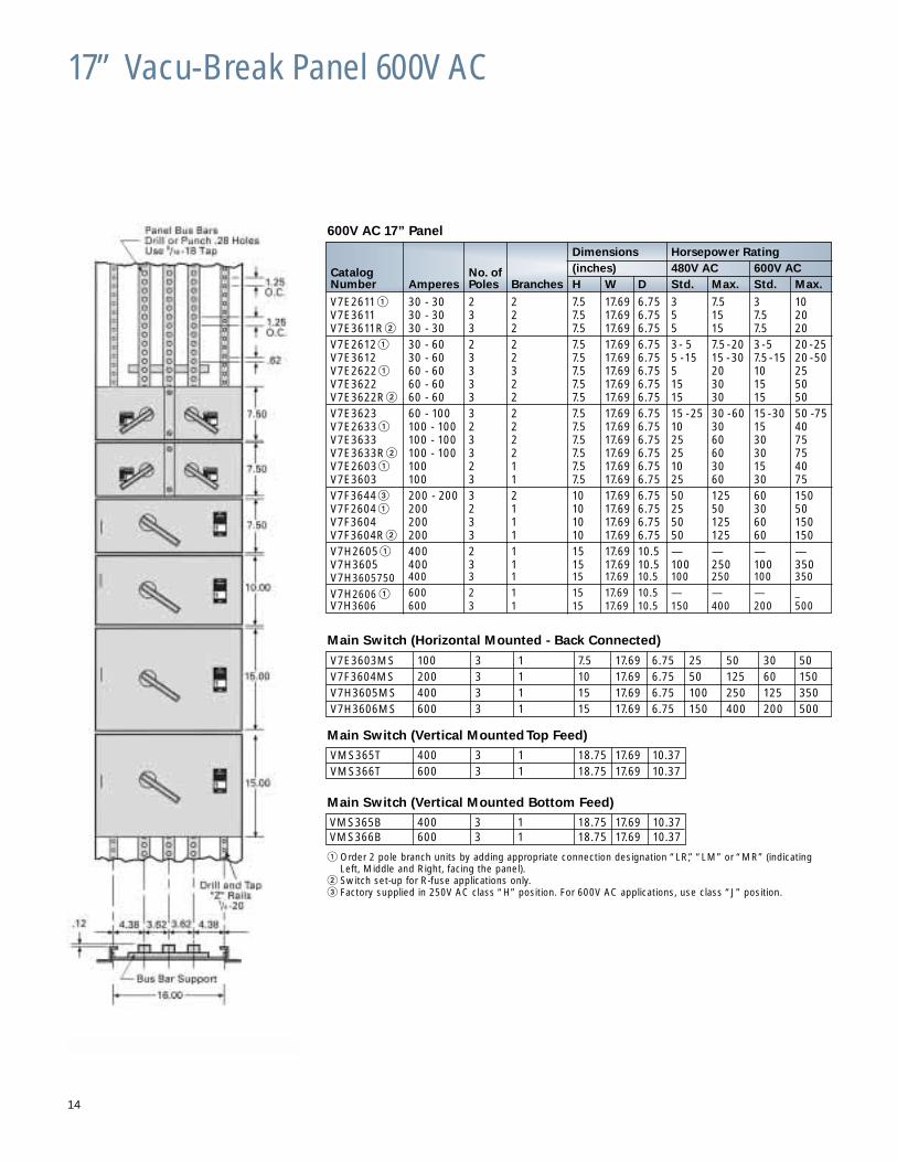
17” Vacu-Break Panel 600V AC
600V AC 17” Panel
Main Switch (Horizontal Mounted - Back Connected)
V7E3603MS 100 3 1 7.5 17.69 6.75 25 50 30 50V7F3604MS 200 3 1 10 17.69 6.75 50 125 60 150V7H3605MS 400 3 1 15 17.69 6.75 100 250 125 350V7H3606MS 600 3 1 15 17.69 6.75 150 400 200 500
Main Switch (Vertical Mounted Top Feed)
VMS365T 400 3 1 18.75 17.69 10.37VMS366T 600 3 1 18.75 17.69 10.37
Main Switch (Vertical Mounted Bottom Feed)
VMS365B 400 3 1 18.75 17.69 10.37VMS366B 600 3 1 18.75 17.69 10.37
� Order 2 pole branch units by adding appropriate connection designation “LR,” “LM” or “MR” (indicating Left, Middle and Right, facing the panel).
� Switch set-up for R-fuse applications only.� Factory supplied in 250V AC class “H” position. For 600V AC applications, use class “J” position.
14
Dimensions Horsepower Rating
Catalog No. of (inches) 480V AC 600V ACNumber Amperes Poles Branches H W D Std. Max. Std. Max.
V7E2611� 30 - 30 2 2 7.5 17.69 6.75 3 7.5 3 10V7E3611 30 - 30 3 2 7.5 17.69 6.75 5 15 7.5 20V7E3611R� 30 - 30 3 2 7.5 17.69 6.75 5 15 7.5 20 V7E2612� 30 - 60 2 2 7.5 17.69 6.75 3- 5 7.5-20 3-5 20-25V7E3612 30 - 60 3 2 7.5 17.69 6.75 5 -15 15 -30 7.5-15 20 -50V7E2622� 60 - 60 3 3 7.5 17.69 6.75 5 20 10 25V7E3622 60 - 60 3 2 7.5 17.69 6.75 15 30 15 50V7E3622R� 60 - 60 3 2 7.5 17.69 6.75 15 30 15 50V7E3623 60 - 100 3 2 7.5 17.69 6.75 15 -25 30 -60 15-30 50 -75V7E2633� 100 - 100 2 2 7.5 17.69 6.75 10 30 15 40V7E3633 100 - 100 3 2 7.5 17.69 6.75 25 60 30 75V7E3633R� 100 - 100 3 2 7.5 17.69 6.75 25 60 30 75V7E2603� 100 2 1 7.5 17.69 6.75 10 30 15 40V7E3603 100 3 1 7.5 17.69 6.75 25 60 30 75V7F3644� 200 - 200 3 2 10 17.69 6.75 50 125 60 150V7F2604� 200 2 1 10 17.69 6.75 25 50 30 50V7F3604 200 3 1 10 17.69 6.75 50 125 60 150V7F3604R� 200 3 1 10 17.69 6.75 50 125 60 150V7H2605� 400 2 1 15 17.69 10.5 — — — —V7H3605 400 3 1 15 17.69 10.5 100 250 100 350V7H3605750 400 3 1 15 17.69 10.5 100 250 100 350
V7H2606 � 600 2 1 15 17.69 10.5 — — — _V7H3606 600 3 1 15 17.69 10.5 150 400 200 500
17” Vacu-Break Accessories
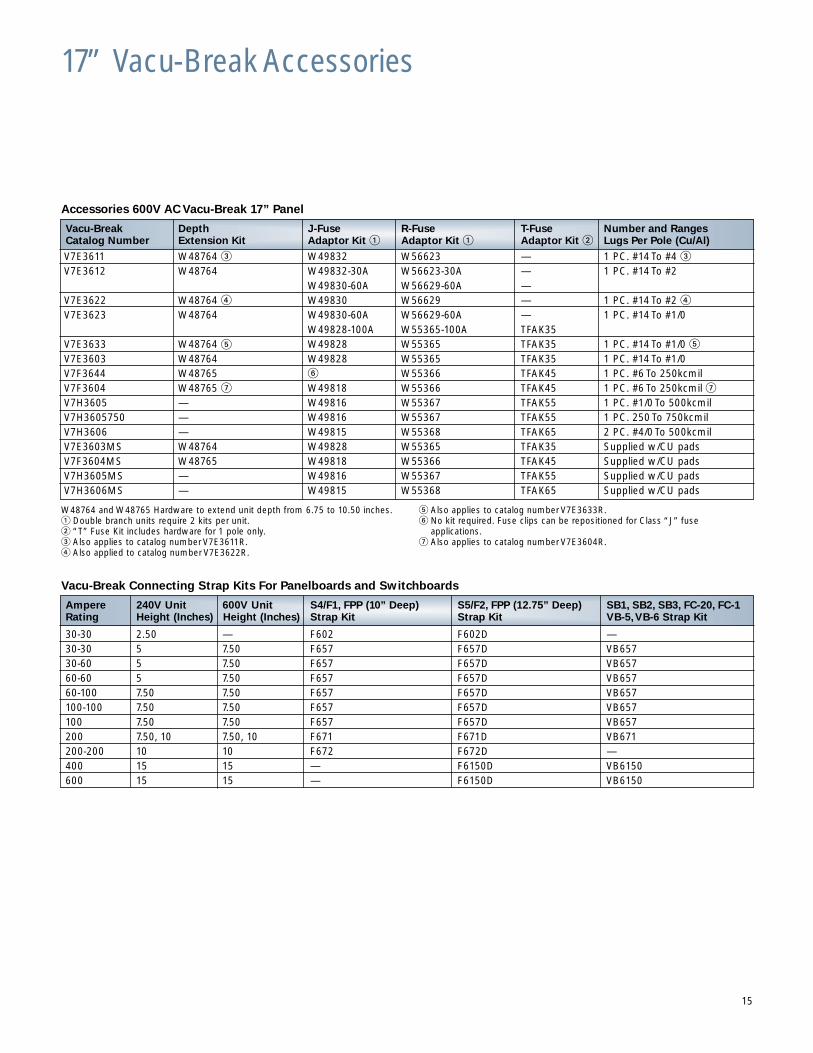
Accessories 600V AC Vacu-Break 17” Panel
Vacu-Break Connecting Strap Kits For Panelboards and Switchboards
Vacu-Break Depth J-Fuse R-Fuse T-Fuse Number and RangesCatalog Number Extension Kit Adaptor Kit � Adaptor Kit � Adaptor Kit � Lugs Per Pole (Cu/Al)
V7E3611 W48764 � W49832 W56623 — 1 PC. #14 To #4 �
V7E3612 W48764 W49832-30A W56623-30A — 1 PC. #14 To #2 W49830-60A W56629-60A —
V7E3622 W48764 � W49830 W56629 — 1 PC. #14 To #2 �
V7E3623 W48764 W49830-60A W56629-60A — 1 PC. #14 To #1/0 W49828-100A W55365-100A TFAK35
V7E3633 W48764 � W49828 W55365 TFAK35 1 PC. #14 To #1/0 �
V7E3603 W48764 W49828 W55365 TFAK35 1 PC. #14 To #1/0V7F3644 W48765 � W55366 TFAK45 1 PC. #6 To 250kcmilV7F3604 W48765 � W49818 W55366 TFAK45 1 PC. #6 To 250kcmil �
V7H3605 — W49816 W55367 TFAK55 1 PC. #1/0 To 500kcmilV7H3605750 — W49816 W55367 TFAK55 1 PC. 250 To 750kcmilV7H3606 — W49815 W55368 TFAK65 2 PC. #4/0 To 500kcmilV7E3603MS W48764 W49828 W55365 TFAK35 Supplied w/CU padsV7F3604MS W48765 W49818 W55366 TFAK45 Supplied w/CU padsV7H3605MS — W49816 W55367 TFAK55 Supplied w/CU padsV7H3606MS — W49815 W55368 TFAK65 Supplied w/CU pads
Ampere 240V Unit 600V Unit S4/F1, FPP (10” Deep) S5/F2, FPP (12.75” Deep) SB1, SB2, SB3, FC-20, FC-1Rating Height (Inches) Height (Inches) Strap Kit Strap Kit VB-5,VB-6 Strap Kit
30-30 2.50 — F602 F602D —30-30 5 7.50 F657 F657D VB65730-60 5 7.50 F657 F657D VB65760-60 5 7.50 F657 F657D VB65760-100 7.50 7.50 F657 F657D VB657100-100 7.50 7.50 F657 F657D VB657100 7.50 7.50 F657 F657D VB657200 7.50, 10 7.50, 10 F671 F671D VB671200-200 10 10 F672 F672D —400 15 15 — F6150D VB6150600 15 15 — F6150D VB6150
W48764 and W48765 Hardware to extend unit depth from 6.75 to 10.50 inches.� Double branch units require 2 kits per unit.� “T” Fuse Kit includes hardware for 1 pole only.� Also applies to catalog number V7E3611R.� Also applied to catalog number V7E3622R.
� Also applies to catalog number V7E3633R.� No kit required. Fuse clips can be repositioned for Class “J” fuse
applications.� Also applies to catalog number V7E3604R.
15
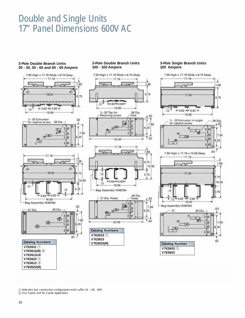
Double and Single Units17” Panel Dimensions 600V AC
3-Pole Double Branch Units30 - 30, 30 - 60 and 60 - 60 Ampere
3-Pole Double Branch Units100 - 100 Ampere
3-Pole Single Branch Units100 Ampere
� Indicates bus connection configuration with suffix LR - LM - MR.� Use 3-pole unit for 2-pole application.
16
Catalog Numbers
V7E2611 �V7E3611(R) �V7E2612LRV7E2622 �V7E3612 �V7E3622(R)
Catalog Number
V7E2603 �V7E3603
Catalog Numbers
V7E2633 �V7E3623V7E3633(R)
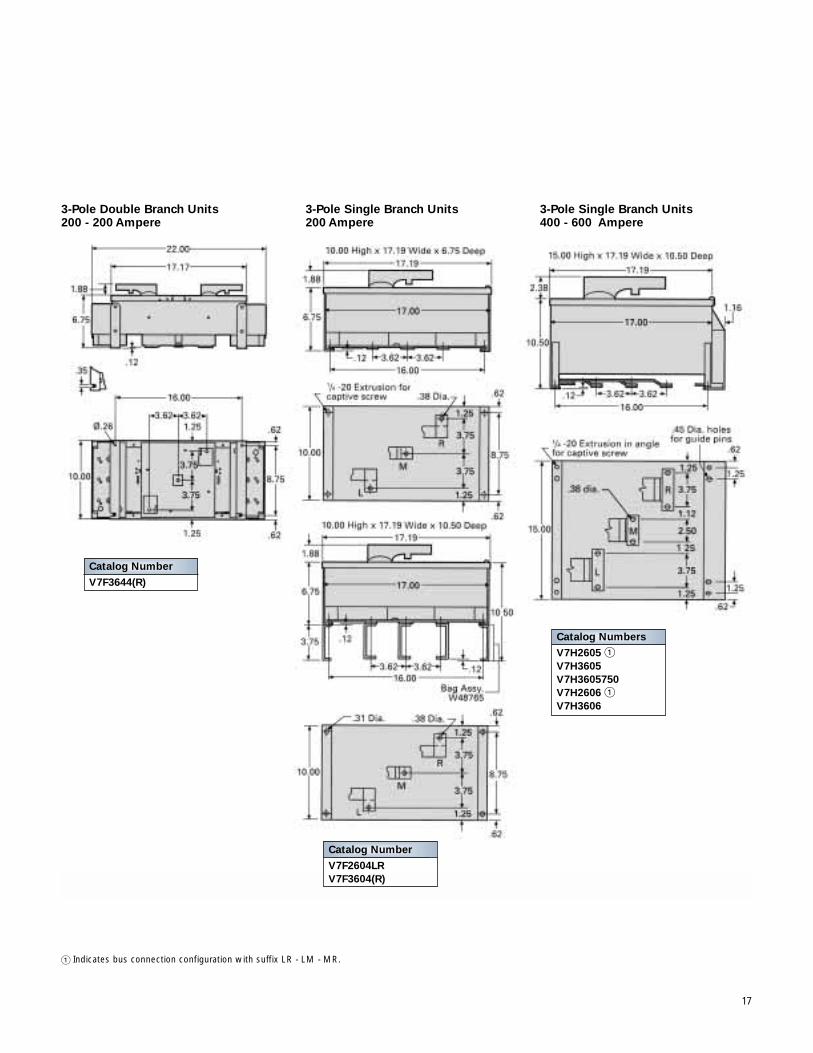
3-Pole Double Branch Units200 - 200 Ampere
3-Pole Single Branch Units200 Ampere
3-Pole Single Branch Units400 - 600 Ampere
17
� Indicates bus connection configuration with suffix LR - LM - MR.
Catalog Number
V7F2604LRV7F3604(R)
Catalog Numbers
V7H2605 �V7H3605 V7H3605750V7H2606 �V7H3606
Catalog Number
V7F3644(R)
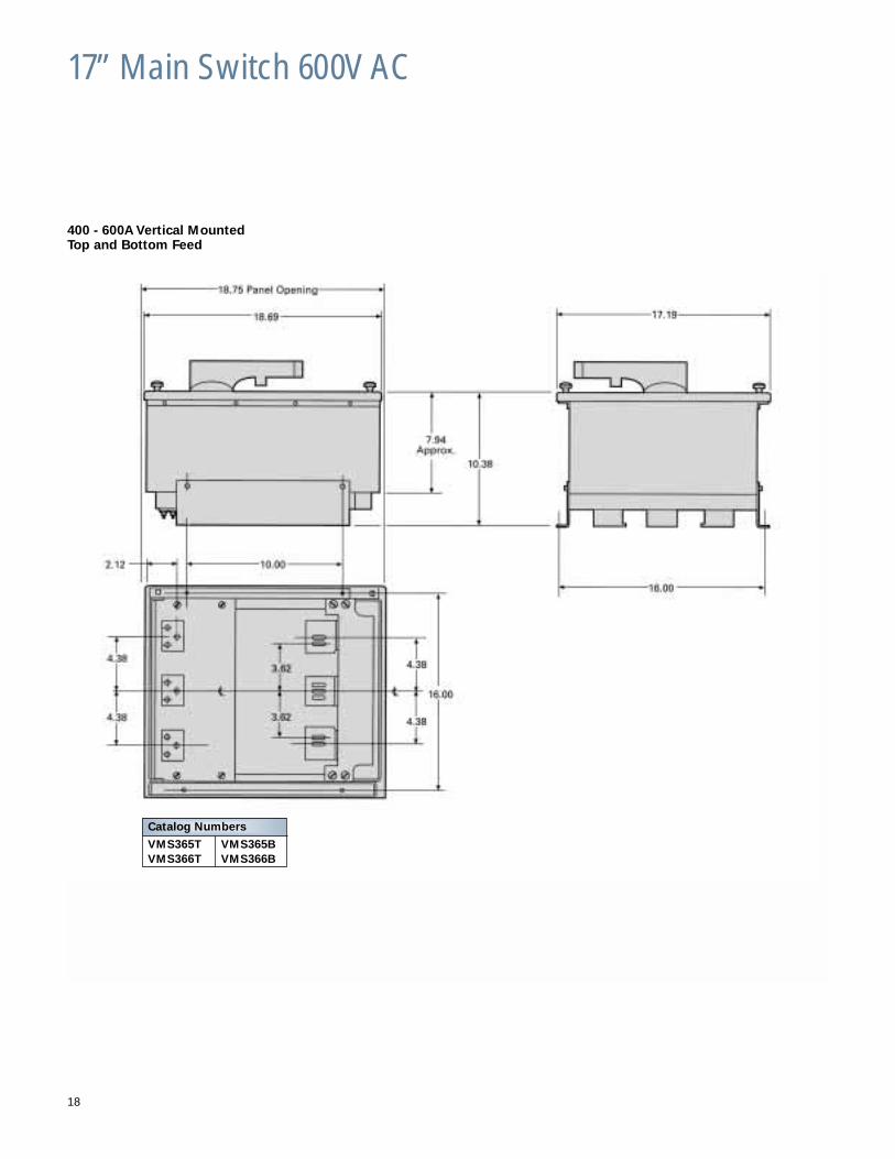
17” Main Switch 600V AC
18
400 - 600A Vertical MountedTop and Bottom Feed
Catalog Numbers
VMS365T VMS365BVMS366T VMS366B
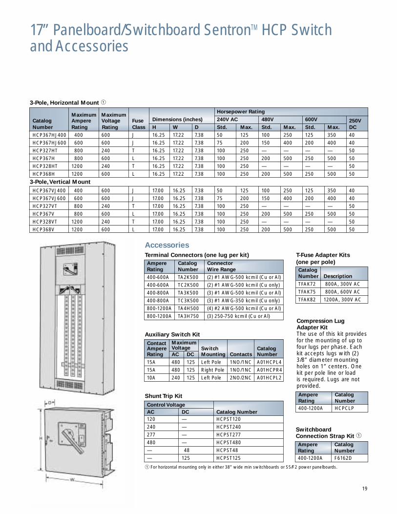
17” Panelboard/Switchboard SentronTM HCP Switch and Accessories
3-Pole, Horizontal Mount �
� For horizontal mounting only in either 38” wide min switchboards or S5/F2 power panelboards.
Maximum MaximumHorsepower Rating
Catalog Ampere Voltage Fuse Dimensions (inches) 240V AC 480V 600V 250VNumber Rating Rating Class H W D Std. Max. Std. Max. Std. Max. DC
HCP367HJ400 400 600 J 16.25 17.22 7.38 50 125 100 250 125 350 40
HCP367HJ600 600 600 J 16.25 17.22 7.38 75 200 150 400 200 400 40
HCP327HT 800 240 T 16.25 17.22 7.38 100 250 — — — — 50
HCP367H 800 600 L 16.25 17.22 7.38 100 250 200 500 250 500 50
HCP328HT 1200 240 T 16.25 17.22 7.38 100 250 — — — — 50
HCP368H 1200 600 L 16.25 17.22 7.38 100 250 200 500 250 500 50
3-Pole,Vertical Mount
HCP367VJ400 400 600 J 17.00 16.25 7.38 50 125 100 250 125 350 40
HCP367VJ600 600 600 J 17.00 16.25 7.38 75 200 150 400 200 400 40
HCP327VT 800 240 T 17.00 16.25 7.38 100 250 — — — — 50
HCP367V 800 600 L 17.00 16.25 7.38 100 250 200 500 250 500 50
HCP328VT 1200 240 T 17.00 16.25 7.38 100 250 — — — — 50
HCP368V 1200 600 L 17.00 16.25 7.38 100 250 200 500 250 500 50
Terminal Connectors (one lug per kit)Ampere Catalog ConnectorRating Number Wire Range
400-600A TA2K500 (2) #1 AWG-500 kcmil (Cu or Al)
400-600A TC2K500 (2) #1 AWG-500 kcmil (Cu only)
400-800A TA3K500 (3) #1 AWG-500 kcmil (Cu or Al)
400-800A TC3K500 (3) #1 AWG-350 kcmil (Cu only)
800-1200A TA4H500 (4) #2 AWG-500 kcmil (Cu or Al)
800-1200A TA3H750 (3) 250-750 kcmil (Cu or Al)
Auxiliary Switch Kit
SwitchboardConnection Strap Kit �
Contact MaximumAmpere Voltage Switch CatalogRating AC DC Mounting Contacts Number
15A 480 125 Left Pole 1NO/1NC A01HCPL4
15A 480 125 Right Pole 1NO/1NC A01HCPR4
10A 240 125 Left Pole 2NO/2NC A01HCPL2
T-Fuse Adapter Kits (one per pole)CatalogNumber Description
TFAK72 800A, 300V AC
TFAK75 800A, 600V AC
TFAK82 1200A, 300V AC
Ampere CatalogRating Number400-1200A HCPCLP
Ampere CatalogRating Number400-1200A F6162D
Accessories
Shunt Trip Kit
Control VoltageAC DC Catalog Number120 — HCPST120
240 — HCPST240
277 — HCPST277
480 — HCPST480
— 48 HCPST48
— 125 HCPST125
Compression LugAdapter KitThe use of this kit providesfor the mounting of up tofour lugs per phase. Eachkit accepts lugs with (2)3/8” diameter mountingholes on 1” centers. Onekit per pole line or load is required. Lugs are not provided.
19
RESET
DOOR OPEN
OFF
ON
13.00
6.256.25
SEE DETAIL ASEE DETAIL B
5.97
LINE
LOADSIDE
SIDE
FILLER PLATE
MOUNTING HOLESFOR 1/4" SCREWSFARSIDE, 4 PLS
90°
8.16
45°
1.254.995
8.74
15.00
EDGE OFDIMPLE
4.99
8.74
15.00
1.24
14.38
VOIDABLEINTERLOCK
GROUND LUG
17.00
6.00
17.22
0.571.07
WIRE CONNECTOR (OPTIONAL)2X
WIRE CONNECTOR(OPTIONAL)
0.98
0.68
1.18
6.05 7.50
0.20
9.22
0.50
0.44
5.002X
ENCLOSUREMOUNTING
5X .228THROUGH
7.23
16.24
DOORLOCKBRKT
16.12
MOUNTING HOLESFOR 1/4" SCREWS4 PLACES
LOAD WIRE CONNECTOR (OPTIONAL)
DETAIL B
1.220.95
1.28
2.00
2X .34 THRU
3 PLACESLINE END
2.703.11
0.64
0.94
1.28
2X 3/8-16 TAPPED
MAX. AVAIL.TERMINAL SURFACE
HOLES THRU
C OF THRU HOLESL
0.06
LUG, REF
DETAIL A
1.001.28
2.00
2X 3/8-16 TAPPED
3 PLACESLOAD END
0.64
HOLES THRU
2.871.34
1.00
2X .34 THRU
LUG, REF
(HARDWARE NOTSHOWN FOR CLARITY)
1
2 34
56
7
8
9
10
1112
13
14
15
16
16
Z RAIL
26
ENCLOSURE
27
SW.
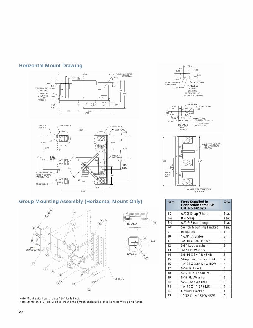
Item Parts Supplied in Qty.Connection Strap KitCat. No. F6162D
1-2 A/CØ Strap (Short) 1ea.3-4 BØ Strap 1ea.5-6 A/C Ø Strap (Long) 1ea.7-8 Switch Mounting Bracket 1ea.9 Insulation 110 1-3/8” Insulator 311 3/8-16 X 3/4” HHMS 312 3/8” Lock Washer 313 3/8” Flat Washer 314 3/8-16 X 3/4” RHSNB 315 Strap Bus Hardware Kit 216 1/4-28 X 3/8” SHWHSW 417 5/16-18 Insert 618 5/16-18 X 1” SRHMS 619 5/16 Flat Washer 620 5/16 Lock Washer 621 1/4-20 X 1” SRHMS 226 Ground Bracket 127 10-32 X 1/4” SHWHSW 2
17
1819
20
21DETAIL A
DETAIL A
0.50
Group Mounting Assembly (Horizontal Mount Only)
Horizontal Mount Drawing
Note: Right exit shown, rotate 180° for left exitNote: Items 26 & 27 are used to ground the switch enclosure (Route bonding wire along flange)
20
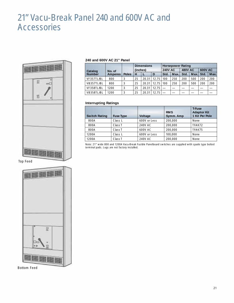
21” Vacu-Break Panel 240 and 600V AC andAccessories
240 and 600V AC 21” Panel
Dimensions Horsepower Rating
Catalog No. of (inches) 240V AC 480V AC 600V AC Number Amperes Poles H L D Std. Max. Std. Max. Std. Max.
VF357TL/BL 800 3 25 20.31 12.75 100 250 200 500 200 200
VB357TL/BL 800 3 25 20.31 12.75 100 250 200 500 200 200
VF358TL/BL 1200 3 25 20.31 12.75 — — — — — —
VB358TL/BL 1200 3 25 20.31 12.75 — — — — — —
Interrupting Ratings
T-FuseRMS Adaptor Kit
Switch Rating Fuse Type Voltage Symm. Amp 1 Kit Per Pole
800A Class L 600V or Less 200,000 None
800A Class T 240V AC 200,000 TFAK72
800A Class T 600V AC 200,000 TFAK75
1200A Class L 600V or Less 100,000 None
1200A Class T 240V AC 200,000 None
Note: 21” wide 800 and 1200A Vacu-Break Fusible Panelboard switches are supplied with spade type boltedterminal pads. Lugs are not factory installed.
Top Feed
Bottom Feed
21
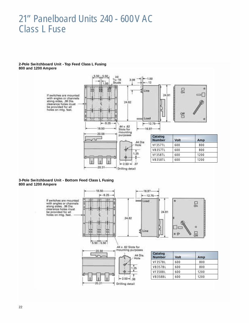
21” Panelboard Units 240 - 600 V ACClass L Fuse
22
2-Pole Switchboard Unit - Top Feed Class L Fusing800 and 1200 Ampere
3-Pole Switchboard Unit - Bottom Feed Class L Fusing800 and 1200 Ampere
CatalogNumber Volt Amp
VF357TL 600 800
VB357TL 600 800
VF358TL 600 1200
VB358TL 600 1200
CatalogNumber Volt Amp
VF357BL 600 800
VB357BL 600 800
VF358BL 600 1200
VB358BL 600 1200
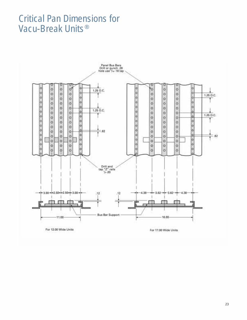
Critical Pan Dimensions forVacu-Break Units®
23
24
The Right Combination for the Best Performance
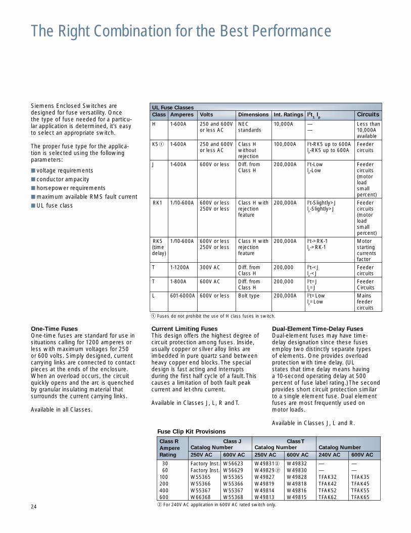
Siemens Enclosed Switches are designed for fuse versatility. Once the type of fuse needed for a particu-lar application is determined, it’s easy to select an appropriate switch.
The proper fuse type for the applica-tion is selected using the following parameters:
■ voltage requirements
■ conductor ampacity
■ horsepower requirements
■ maximum available RMS fault current
■ UL fuse class
One-Time FusesOne-time fuses are standard for use insituations calling for 1200 amperes orless with maximum voltages for 250 or 600 volts. Simply designed, currentcarrying links are connected to contactpieces at the ends of the enclosure.When an overload occurs, the circuitquickly opens and the arc is quenchedby granular insulating material that surrounds the current carrying links.
Available in all Classes.
Current Limiting FusesThis design offers the highest degree ofcircuit protection among fuses. Inside,usually copper or silver alloy links areimbedded in pure quartz sand betweenheavy copper end blocks. The specialdesign is fast acting and interrupts during the first half cycle of a fault. Thiscauses a limitation of both fault peakcurrent and let-thru current.
Available in Classes J, L, R and T.
Dual-Element Time-Delay FusesDual-element fuses may have time-delay designation since these fusesemploy two distinctly separate types of elements. One provides overload protection with time delay. (UL states that time delay means having a 10-second operating delay at 500 percent of fuse label rating.) The secondprovides short circuit protection similarto a single element fuse. Dual elementfuses are most frequently used onmotor loads.
Available in Classes J, L and R.
UL Fuse ClassesClass Amperes Volts Dimensions Int. Ratings l2t
1 lp
Circuits
H 1-600A 250 and 600V NEC 10,000A — Less thanor less AC standards — 10,000A
available
K5 � 1-600A 250 and 600V Class H 100,000A l2t-RK5 up to 600A Feederor less AC without lp-RK5 up to 600A circuits
rejection
J 1-600A 600V or less Diff. from 200,000A l2t-Low FeederClass H lp-Low circuits
(motorload small percent)
RK1 1/10-600A 600V or less Class H with 200,000A l2t-Slightly>J Feeder250V or less rejection lp-Slightly>J circuits
feature (motorloadsmallpercent)
RK5 1/10-600A 600V or less Class H with 200,000A l2t->RK-1 Motor(time 250V or less rejection lp->RK-1 startingdelay) feature currents
factor
T 1-1200A 300V AC Diff. from 200,000 l2t-<J FeederClass H lp-<J circuits
T 1-800A 600V AC Diff. from 200,000 l2t=J FeederClass H lp=J Circuits
L 601-6000A 600V or less Bolt type 200,000A l2t=Low Mainslp=Low feeder
circuits� Fuses do not prohibit the use of H class fuses in switch.
Fuse Clip Kit Provisions
� For 240V AC application in 600V AC rated switch only.
Class R Class J Class TAmpere Catalog Number Catalog Number Catalog NumberRating 250V AC 600V AC 250V AC 600V AC 240V AC 600V AC
30 Factory Inst. W56623 W49831� W49832 — —60 Factory Inst. W56629 W49829� W49830 — —
100 W55365 W55365 W49827 W49828 TFAK32 TFAK35200 W55366 W55366 W49819 W49818 TFAK42 TFAK45400 W55367 W55367 W49814 W49816 TFAK52 TFAK55600 W66368 W55368 W49813 W49815 TFAK62 TFAK65
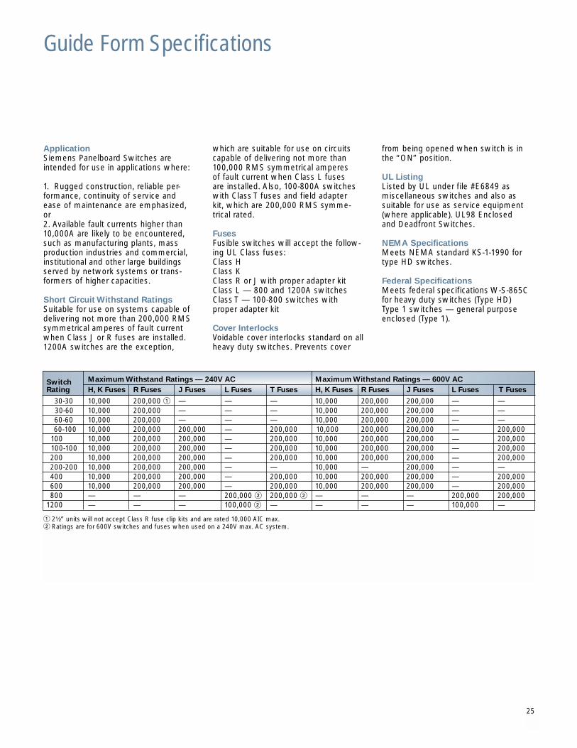
ApplicationSiemens Panelboard Switches areintended for use in applications where:
1. Rugged construction, reliable per-formance, continuity of service and ease of maintenance are emphasized,or2. Available fault currents higher than10,000A are likely to be encountered,such as manufacturing plants, massproduction industries and commercial,institutional and other large buildingsserved by network systems or trans-formers of higher capacities.
Short Circuit Withstand RatingsSuitable for use on systems capable ofdelivering not more than 200,000 RMSsymmetrical amperes of fault currentwhen Class J or R fuses are installed.1200A switches are the exception,
which are suitable for use on circuitscapable of delivering not more than100,000 RMS symmetrical amperes of fault current when Class L fuses are installed. Also, 100-800A switcheswith Class T fuses and field adapterkit, which are 200,000 RMS symme-trical rated.
FusesFusible switches will accept the follow-ing UL Class fuses:Class HClass KClass R or J with proper adapter kitClass L — 800 and 1200A switchesClass T — 100-800 switches with proper adapter kit
Cover InterlocksVoidable cover interlocks standard on allheavy duty switches. Prevents cover
from being opened when switch is inthe “ON” position.
UL ListingListed by UL under file #E6849 as miscellaneous switches and also assuitable for use as service equipment(where applicable). UL98 Enclosed and Deadfront Switches.
NEMA SpecificationsMeets NEMA standard KS-1-1990 fortype HD switches.
Federal SpecificationsMeets federal specifications W-S-865Cfor heavy duty switches (Type HD)Type 1 switches — general purposeenclosed (Type 1).
Switch Maximum Withstand Ratings — 240V AC Maximum Withstand Ratings — 600V ACRating H, K Fuses R Fuses J Fuses L Fuses T Fuses H, K Fuses R Fuses J Fuses L Fuses T Fuses
30-30 10,000 200,000 � — — — 10,000 200,000 200,000 — —30-60 10,000 200,000 — — — 10,000 200,000 200,000 — —60-60 10,000 200,000 — — — 10,000 200,000 200,000 — —60-100 10,000 200,000 200,000 — 200,000 10,000 200,000 200,000 — 200,000
100 10,000 200,000 200,000 — 200,000 10,000 200,000 200,000 — 200,000100-100 10,000 200,000 200,000 — 200,000 10,000 200,000 200,000 — 200,000200 10,000 200,000 200,000 — 200,000 10,000 200,000 200,000 — 200,000200-200 10,000 200,000 200,000 — — 10,000 — 200,000 — —400 10,000 200,000 200,000 — 200,000 10,000 200,000 200,000 — 200,000600 10,000 200,000 200,000 — 200,000 10,000 200,000 200,000 — 200,000800 — — — 200,000 � 200,000 � — — — 200,000 200,000
1200 — — — 100,000 � — — — — 100,000 —
� 2¹⁄₂” units will not accept Class R fuse clip kits and are rated 10,000 AIC max.� Ratings are for 600V switches and fuses when used on a 240V max. AC system.
25
Guide Form Specifications
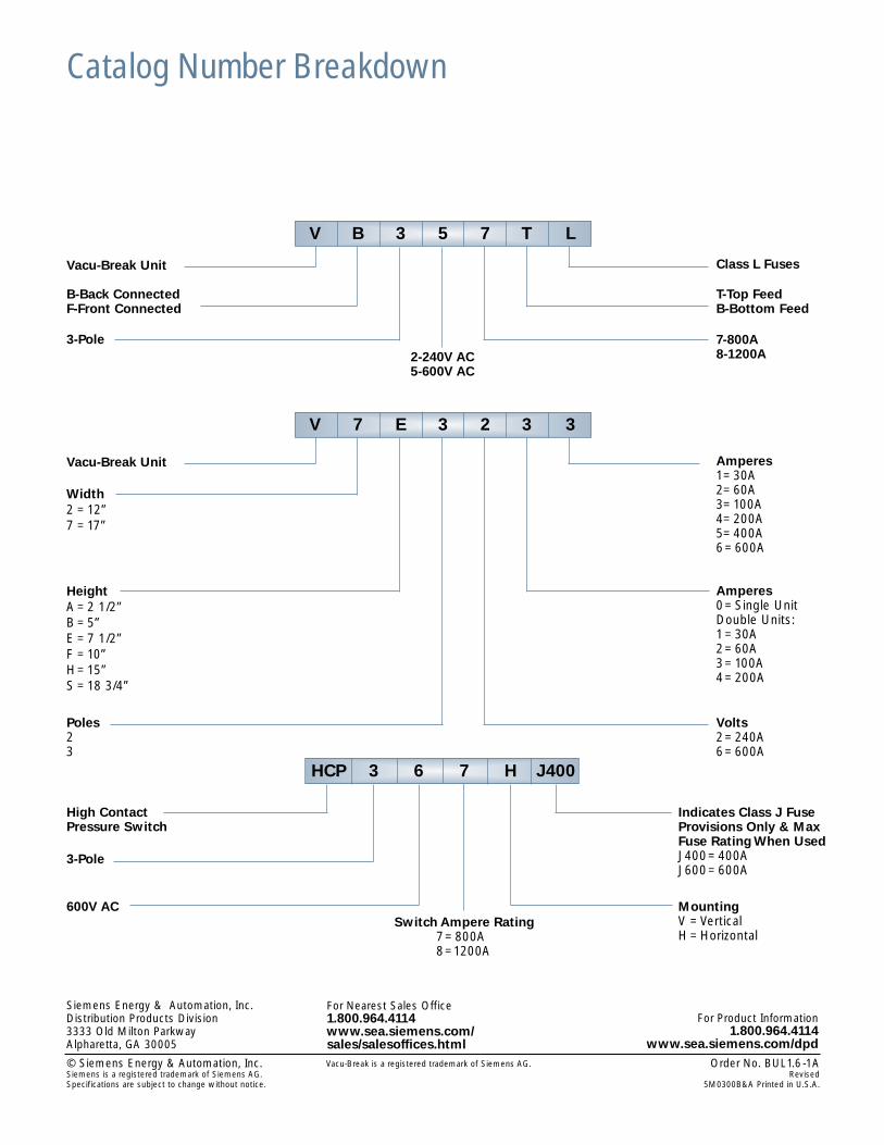
Catalog Number Breakdown
V B 3 5 7 T L
Vacu-Break Unit Class L Fuses
B-Back ConnectedF-Front Connected
3-Pole2-240V AC5-600V AC
T-Top FeedB-Bottom Feed
7-800A8-1200A
HCP 3 6 7 H J400
High ContactPressure Switch
Indicates Class J FuseProvisions Only & Max Fuse Rating When UsedJ400=400AJ600=600A
3-Pole
600V ACSwitch Ampere Rating
7=800A8=1200A
MountingV =VerticalH =Horizontal
V 7 E 3 2 3 3
Vacu-Break Unit Amperes1=30A2=60A3=100A4=200A5=400A6=600A
Width2 =12”7 =17”
Poles23
HeightA =2 1/2”B =5”E =7 1/2”F =10”H=15”S =18 3/4”
Amperes0=Single UnitDouble Units:1=30A2=60A3=100A4=200A
Volts2=240A6=600A
Siemens Energy & Automation, Inc.Distribution Products Division3333 Old Milton ParkwayAlpharetta, GA 30005
© Siemens Energy & Automation, Inc. Order No. BUL1.6-1A Siemens is a registered trademark of Siemens AG. RevisedSpecifications are subject to change without notice. 5M0300B&A Printed in U.S.A.
For Nearest Sales Office1.800.964.4114 www.sea.siemens.com/sales/salesoffices.html
For Product Information1.800.964.4114
www.sea.siemens.com/dpdVacu-Break is a registered trademark of Siemens AG.