Embed Size (px)
Citation preview
SELECTION AND TESTING OF PYROMETERS FOR HIGH-TEMPERATURE GAS FLOW
by
EIJ)ON OREN MERKLIN
A THESIS
submitted to
OREGON STATE COLLEGE
in partial fulfillment of the requirements for the
degree of
MASTER OF SCIENCE
June 1953
AFPBOIEDT
Redacted for Privacy
hofirr of lcchmlorl futalalag Ia euroIrsEr of IeJu
Redacted for Privacy
Redacted for Privacy
thatrau of tohrel Oruet Ormrtttt
Eoar of 0rleto Sohsal
Redacted for Privacy
Drampc thtrlr l Wba 1p by Br Orgrlr IiLLta
ACKNOWLEDGEMENTS
This project could not have been carried out
without the helpful guidance given by Professor A D Hughes
of t he Department of Mechanical Engineering
The author also wishes to extend t hanks to the
Driver- Harris Company for the donation of the samples of
Inconel and Chromax wire and to Mr_ Don Deardorf of the
United States Bureau of Mines for his assistance in conshy
ducting t he temperature versus resistance tests on t he wire
The assistance given by several graduate students
C S Robins R W Peterson P Pouderoux and G Jabusch
in conducting the tests is greatly appreciated The author
also wishes to thank his wife Gayle for h er many hours of
assist ance on t h e t hesis
bull bull bull bull bull
bull bull bull bull bull bull bull bull bull bull bull bull bullbull bull bull bull bull bull bull bull bull
TABLE OF CONTENTS
Page
DlTRODUCTION bullbull bull bull bull bull bull bull bull bull bull bull bull bull bull bull bull bull bull bull bull 1
SELECTION OF THE PYROMETER bull bull bull bull bull bull bull bull bull bull bull bull bull bull 7
Thermocouples bull bull bull bull bull bull bull bull bull bull bull bull bull bull bull bull bull bull 8 Sonic Pyrometer bull bull bull bull bull bull bull bull bull bull bull bull bull bull bull bull bull 12 Pneumatic Pyrometer bull bull bull bull bull bull bull bull bull bull bull bull bull bull bull 16 Resistance Thermoelement bull bull bull bull bull bull bull bull bull bull bull bull 20
THEORY OF TEMPERATURE MEASUREMENT BY THERMOCOUPLES AND RESIST ANCE THEm~OELEMENTS bull bull bull bull bull bull bull bull bull bull bull 23
Heat Loss Due to Conduction bull bull bull bull bull bull bull bull bull 27 Heat Loss by Radiation bull bull bull bull bull bull 29 Heat Gain by Radiati9n bull bull bull bull bull bull bull bull bull bull bull bull 34bullHeat Gain Due to Kinetic Energy Change bull bull bull bull bull 35
CONSTRUCTION AND PLACEMENT OF PYROMETERS AND EQUIPMENT bull bull bull bull bull bull bull bull bull bull bull bull bull bull bull bull bull bull bull 39
Silver-Shielded Thermocouples bull bull bull bull bull bull bull bull bull bull Resistance Thermoelement bull bull bull bull bull bull bull bull bull bull bull bull Pressure Probe Section bull bull bull bull bull bull bull bull bull bull bull bull 44i
TESTS bull bull bull bull bull bull bull bull bull bull bull bull 47 Apparatus bull bull bullbull bull bull bull bull bull bull bull bull bull bull bull bull 47 Procedure bull bull bull bull bull bull bull bull bullbull bull bull bull bull bull bull bull bull bull bull bull 49
RESULTS 52 CONCLUSIONS bull bull bull bull bull bull bull 63
RECOMMENDATIONS FOR FUTURE INVESTIGATIONS bull bull bull bull bull bull 65 BIBLIOGRAPHY bull bull bull bull bull bull bull bull bullbull bull bull bull bull bull bull bull bull bull bull 67 APPENDIX A bull 69
APPENDIX B bull bull bull bull bull bull bull bull bull bull bull bull bull bull bull bull bull bull bull bull bull bull 79
LIST OF FIGURES
Figure Page
l The Oregon State College Gas Turbine bullbull bull bullbull 2
2a Diagr ammatical Sketch of Previous Thermoshycouple Inst allations bullbullbullbullbullbullbullbullbull bull bull bull 4
2b Plan View of Elliptical Section bull bull bull bull bull bull bull 4 3middot Double-Shielded Thermocouple
Center Shield Electrically Heated bull bull bull bull bull ll
Sonic Pyrometer bull bull bull bull bull bull bull bull bull bull bull bull bull bull bull 14
5a Fairchild Pneumatic Pyrometer 17
5b Pneumatic Pyrometer bull bull bull bull bull bull bull bull bull bull bull bull bull 17
6 Simple Thermocouple Circuit bull bull bull bull bull bull bull bull bull 24 7 Wheatstone Bridge Circuit bull bull bull bull bull bull bull bull bull bull 24 8 Effects of Conduction on the Temperature
Measured by A Thermocouple bull bull bull bull _ bull 30
Effects of Radiation on the Temperature Measured by A Silver-Shielded Thermocouple bull 33
10 Effects of Velocity on the Temperature Measured by A Thermocouple bull bull bull bull bull bull bull bull bull 37
11 Exploded View of Thermocouple and Its Support 42 12 Typical Assembly of Thermocouple and Support bull 43 13 Pressure Probe Section bull bull bull bull bull bull bull bull bull bull bull bull 45 14 Electrical Circuit for Thermocouples bull bull bull bull bull 48 15 Electrical Circuit for Resist ance Thermoshy
elements bull bull bull bull bull bull bull bull bull bull bull bull bull bull bull bull bull bull 48 16 Temperatures as Measured by t he Silvershy
Shielded Thermocouple bull bull bull bull bull bull bull bull bull bull bull 53
17 Temperature as Measured by the Bare Thermocouples bull bull bull bull bull bull bull bull bull bull bull bull bull bull bull 55
18 Comparison of Average Inlet Temperatures as Measured by A Silver-Shielded and A Bare Thermocouple bull bull bull bull bull bull bull bull bull bull bull bull bull bull bull bull 56
bull bull bull
bull bull bull bull
Figure
20
21
Page
The Effect of Temperature on the Resistance of No 20 Inconel Wire bullbullbullbullbullbullbullbullbullbullbull 59
Effects of Tempera ture on the Resistance of A 660 Watt Nichrome Heater Element 6o
Theoretical Turbine Inlet Temperature Assuming Complete Combustion and No Heat Loss bull bull bull bull bull bull bull bull bull bull bull bull bull 78
SELECTION AND TESTING OF PYROMETERS FOR HIGH-TEMPERATURE GAS FLOW
INTRODUCTION
With the steadily increasing importance of the gas
turbine in the last few years the problem of measuring the
temperature of the combustion gases accurately in order to
determine the operating conditions of the unit has become
very important This problem has been quite evident in the
Oregon State College gas turbine This turbine was conshy
structed by a group of students under the supervision of
Professor Arthur D Hughes from a war surplus B-31 turboshy
supercharger with a De Havilland H-1 jet eng ine combustion
chamber A picture of the second complete unit is shown in
Figure 1shy
Since this unit was built it bas been evident
that the temperatures being measured at the turbine inlet
and the turbine exhaust were very much in error Neither
the turbine inlet temperature nor the turbine exhaust temshy
perature was consistent At times the turbine inlet temshy
perature indicated would be 1400 F to 1500 F and at other
times it would be closer to 1000 F under the s ame operating
conditions When an attempt was made to plot the temperashy
ture as ordinate with various abscissas such as turbine
speed turbine expansion ratio and air-fuel ratio there
was no correlation at all The points plotted were widely
2
3
scattered and did not indicate a trend through wh ich a curve
could be drawn
Theoretically in order to do work by passing a
gas through a turbine wheel there must be a temperature drop
and a pressure drop The required pressure drop across thebull
turbine is quite easily measured but to date the measured
temperature or the exhaust gases has always been greater
than the temperature of the inlet gases This is another
indication that the temperatures have not been accurately
measured
In the second unit the t hermocouples measuring the
turbine inlet temperature were placed in two locations The
first location was in a hollow stainless steel staybolt
while the second location was about 3 or 4 inches ahead or the hollow staybolt in a removable elliptical steel section
These two locations are shown diagrammatically in Figure 2a
As may be seen from Figure 2b the elliptical section was
made in such a manner that four t hermocouples could be
placed in the section at once
The exhaust thermocouples measuring the turbine
exhaust temperatures were placed in three positions 120
degrees apart around the exhaust ring These three thermoshy
couples were approximately 3 inches from the turbine wheel
When an attempt was made to explain the reasons
for t h e peculiar temperatures measured it was thought that
CombuatiOD Chlmbtr
( a ) (b)
FIGUFE 2 (a) DI A middot~ Jn~T IC AL Sr~middot~TC H OF PREVIOUS THERMOC OUPLE IUSl ALLAIlOJ S (b) PLAN VI~W OF ELLI PTICAL SECTION
5
there were several factors causing the inconsistency Since
the thermocouples placed in the elliptical section were
actually at the throat of tha exhaust of the combustion
chamber the velocity at that section was quite high--in the
order of 200 to 500 feet per second Therefore the portion
of the gas that slows up as it approaches the thermocouple
imparts a portion of its kinetic energy to the thermocouple
increasing its temperature above that of the static gas
temperature Also the location of these thermocouples in
the elliptical section made it possible for the thermoshy
couples riot only to see the flame but also to bullsee the
cold walls of the section This gas radiation to the
thermocouple tends to increase the thermocouple 1 s temperashy
ture while the thermocouples radiation to the cold walls
tends to reduce its temperature For a time it was thought
that the radiation loss caused by the cold walls would tend
to offset the gain in temperature caused by the gas radiashy
tion and by the kinetic energy of the gas Since the temshy
perature measurements were inconsistent however this idea
was discarded Various stainless steel shields were tried
several times but they did not correct the situation
The thermocouple placed in the hol~ow staybolt
actually had a stainless steel shield around it so some of
the radiation loss and gain should have been decreased but
the thermocouple junction measured a temperature several
6
hundred degrees lower t h an t hat measured by the thermoshy
couples in the elliptical section This difference was beshy
lieved to be caused by the radiation gain by the thernwbull
couples in the elliptical section due to r adiation from the
flame and by the conduction loss along the hollow stainless
steel staybolt
The exhaust thermocouples have three factors
entering into possible causes for errors in their readings
These factors are the kinetic energy change due to slowing
up of the gases as they pass the junction and the heat
radiated to and from the thermocouple
Since t his gas turbine was built f or a dual
purpose (demonstration and testing) it is necessary to
measure with a certain degree of accuracy t h e temperature at
various critical points in order to conduct a worthwhile
test As has been previously stated up until this time
these temperatures h ave not been measured accurately It is
the purpose of this thesis therefore to select and test
several pyrometers which can be used for high-temperature
gas stream measurement If the tests should prove that a
pyrometer can measure the required temperatures accurately
it will be used as a permanent temperature-measuring instrushy
ment for the turbine
7
SELECTION OF THE PYROMETER
A pyrometer must have certain requirements for
each individual installation in order to be able to measure
the temperature of the gas stream accurately In this inshy
stallation it is desired to measure the static temperature
rather than the total temperature as is commonly measured in
high-temperature gas streams These two terms are defined
as follows
1 Stmiddotatie temperature is that temperature which
would be indicated on a recording instrument
if the temperature- measuring device were
traveling with zero relative velocity with
the gas stream
2 Total temnerature is that temperature which
would be indicated on a recording instrument
if the t emper-ature-measuring device were
stationary and the measuring device absorbed
all of the energy given up by the gases as the
gas velomiddoteity approached zero
The statie temperature is the temperature desired
since it is t h is temperature along with the static pressure
that completely defines the thermodynamic state of the gas
(3 p bull219) bull Therefore the pyrometer selected must measure
thei static temperature or lt must be possible to corremiddotet
the measur-ed temperature to give the static temperature In
8
this installation it is expected that the gas streams
temperature varies across the turbine casing so the pyromshy
eter either must measure the average temperature or it must
be adaptable for use in a temperature traverse It is known
also that at any one point there is a rapid temperature
fluctuation therefore the response rate of the pyrometer
need not be fast in order to obtain the desired average
temperature
The pyrometer also must reduce the radiation --shy
conduction and convection losses to a minimum Other reshy
quirements that should be met are simplicity low cost
reliability and durability
There are many different pyrometers for measuring
temperatures but only a few of these methods will meet the
above requirements Some of the most used methods are as
follows
1 Thermocouples both bare and shielded
2 Sonic pyrometer
3middot Pneumatic pyrometer
4 Resistance thermoelement
A brief discussion of each pyrometer is given below
Thermocouples
Pyrometers employing thermocouples have become
quite popular over a period of years due to their simplicity
accuracy low cost and ease of production However they
9
still are subject to errors such as conduction los~ along
the wires and along the thermocouple well radiation loss
rrom the thermocouple junction to the cold walls radiation
gain rrom the hot gases to the junction and impact error
due to the high-velocity gases striking the thermocouple
Also they have an inherent property of only being able to
measure the temperature at one small point In order to
obtain an average temperature therefore it would be necesshy
sary to use many thermocouples and average the readings
Numerous investigators lt4 pp l53-160) (11 pp
421-425) and (16 p334) have attempted to correct the readshy
ings or a thermocouple by incorporating various forms of
shielding to reduce the errors due to radiation It has
been reported by A I Dahl and E F Flock that if a silver
shield were pressed on a thermocouple the errors due to
radiation would be negligible lt4~ plS6) This same silverbull
shielded thermocouple gives excellent performance because of
its ruggedness rapid response and ease of construction
Another type of radiation shielding consists of
two tubes concentrically placed with the thermocouple in the
center (16 p bull334) Another thermocouple is placed between
the two concentric tubes and a coil of wire is wrapped
around the center tube This cot l of wire is connected in
series with a voltage source and a current-limiting device
During operation the current is adjusted in the coil until
10
the two thermocouples indicate the same temperature At
this point the center shield is at the same temperature as
the main thermocouple so there can be no heat loss due to
radiation from the main thermocouple to the first shield~ A
sketch of this thermocouple is shown in Figure 3bull This
thermocouple gives very good results but due to its conshy
struction and elaborate control necessary to maintain the
center shield at the required temperature it is only suitshy
able for installations in which the temperature is relativeshy
ly constant
Another shield used by Wbull J King (11 Pbull424gt uses
a thermocouple with quadruple shields spaced 116 inches
apart~ These shields are 2-12 inches long and made of 18-8
stainless steel The accuracy of this thermocouple is not
quite as good as that of the other two and due to its large
outside diameter 1-18 inches it is limited to use in
large-size ducts~
Shielding of various forms and sizes also has been
used in trying to obtain the maximum amount of heat transshy
fer from the change in kinetic energy due to stopping the
gases by the thermocouple W J King reports on a
diffuser-type shield probe (11 P~424l used to avoid velocshy
ity er~ors which has been quite successfUl for velocities
from 150 to 600 feet per second and at room temperatures
11
Voltage Source
Ma Th
1Ull1voltmetera
Mar( AliI I ~ I I L----1s J
in f-Auxilia7 ermocouElbullshy Thermooou2lbull
~
I 1 Cka I n
L Heater
FIGURE 3 DOUBLE-SHIBLDED THRMOCOUPLB CENTER SHIELD BLECTRICALLY HEATED middot
12
This probe however does not have adequate shielding for
radiation so it is unfit for high-temperature usage
Another group of investigators (1 pp338-J4l) has
reported on numerous designs of shielding to be used to reshy
cover the maximum runount of kinetic energy in the gas The
shields developed recovered nearly all of the total availshy
able energy caused by the change in velocity in the form of
heat and so they measure the total temperature quite accushy
rately In this case however the static temperature is
the one desired so they would not be suitable for this use
unless the velocity at the location of the thermocouple were
known
Sonic Pyrometer
The sonic pyrometer (17 pp851-858) was developed
by E P Walsh Sidney Allen and J R Hamm for the express
purpose of measuring the total temperature of a highshy
temperature low-density gas stream This type of pyrometer
incorporates three essential parts the thermocouple the
flow nozzle and the encasing tube but other parts may be
added depending upon the accuracy desired For instance
in order to decrease radiation a second tube is placed
around the first and gas is drawn through the annular space
raising the inner tube temperature to that of the gas middot In
order to decrease conduction loss the high-velocity gas may
be allowed to pass over the therrnocouple wfres for a short
13
distance A sketch of this type of pyrometer is shown in
Figure 4- The principle upon which this pyrometer operates
is that if a gas is allowed to pass through a flow nozzle at
such a rate that its velocity approaches the velocity of
sound and that if a thermocouple is placed within the flow
of this gas stream then a maximum amount of heat will be
transferred to the thermocouple giving the maximum temperashy
ture obtainable This point of operation may be found by
varying the gas flow through the nozzle When the flow
reaches such a point that the temperature of the thermoshy
couple does not increase then sonic velocity is obtained
The true static temperature then may be found by applying
the following equation
(1)
where ls Static temperature R
Tj =Junction temperature R
V =Velocity ftsec
g =Acceleration of gravity ftsec2
J =Heat equivalent of work Btuft lb
cp bull Specific heat at constant pressure Btulb R
102 bull Conversion factor for obtaining themiddottotal temperature of the gas stream (17 p852)
Gas Flop
To Suction
o K1111Yoltmeter Plow
l
FIGURE 4 SONI C PYROMETER
15
fhis type of pyroraeter then gives a relatively
simple method for measuring the static gas temperature of
not only constant- temperature gas streams but also of
rapidlychanging- temperature gas streams due to lts rapid
response rate
Certain eharaeterlstic features of this instrushy
ment however make it less desirable for this application
For instance with -a suction pyrometer correeted for r-adiashy
tion two suction pumps must be used and their coat plus the
cost of construction or the pyrometer will give a high total
cost Also in order to calibrate the pyrometer in the
easiest possible manner it take-s quite an elaborate and
costly selection of instruments Walshbull Allanbull and Hamm
used a gravimeirie chemical analysis of the gas stream in
order to obtain the true temperature This grtavimetrtc
technique as described by L1oyd (12 pp 335 34l) ha-s proved
to be quite accurate
This pyrometer is only capable of obtaining the
temperature at ane point in the gas stream ln order to
obtain a true average temperature either a time-consuming
temperature traverse would have to be talten or several
sonic pyrometers would have to be installed at various pomiddotaishy
tions which would further increase the cost bull
Still another disadvantage is that this pyrometer
requires a definite amount of gas to be drawn off through
16
the pyrometer In this ease the amount of gas flow in the
unit is critical and all gas flow should be used in driving
the turbine bull
Pneumatic Pyrometer
The pneumatic pyrometer as developed by the Fairshy
child Camera and Instrument Company (15 pp30-34) is a
relatively simple device It consists of a tube containing
two small orifices with a heat exchanger located between
these orifices A sketch of this instrument is shown in
Figure 5a In order to measure the temperature of the gas
stream a sample of gas is drawn into the tube and passed
through the first orifice~ The gas is then cooled by the
heat exchanger and is passed through the second orifice
after which it is discharged into the atmosphere It is
then only necessary to measure the pressure drop across both
orifices and the temperature at the second orifice These
values are then used with the equation
(2
where - Static temperature before the first orifice RTsl shy- Static temperature before the second orifice RTs2 shy- Static pressure before the first orifice psiaPsl shy
Static pressure before the second orifice psiaPs2 = Static pressure after the second orifice psi aPs3 =
17
bull
Heat Exchanger
1 CoJQbu1tion Oyta
FIGURE Sa PAIRCHILD PNEUMATIC PYROMETER
Gae now Probe
o Draft Gagel
~ To Suction
FIGURE 5b PNEUMATIC PYROMETER
18
K =Constant cont aining the orifice coefficients and areas
when the difference (Psl- Ps2) is small
With t h is t yp e of instrument it is possible to
c alculate the temperature of the gas ~t~eam very closely
This is due to t h e fact that t h e only he at loss will be by
radiation from the gas to the walls wh ich is a very small
amount The response of this instrument is almost instanshy
taneous since the density of the gas stream changes with
temperature and any change in density must immediately afshy
feet the pressure drop across the first orifice
Like the sonic pyrometer t h is instrument has the
inherent property of only being able to measure the temperashy
ture at one point and while doing so a sample of gas must
be by- passed through the instrument both of which are conshy
sidered undesirable in t h is case
Another type of pneumatic pyrometer (Figure 5b) is
that developed by J A Clark and W Ht Rohsenow ( 3 pp 219shy
227 ) bull In t his pyrometer a portion of gas is pulled through
a tube by a suction pump in a way s imilar to that used with
the sonic pyrometer Various values of pressure are measured
at the inlet to the tube and the flow is measured by an
orifice after the gas has passed t hrough a heat exchanger
These values are t hen used in Equation 3 to find the static
temperature at the inlet to the probe
19
3)
where Tsl bull Static temperature R
Conversion faetor 322 lbmsee2 lbf
~ Gas constant ft lbflbm R
Static pressure lbfft2
2bull Mass flow lbmsec rt
bull Ratio of specific heats dimensionless
Total pressure lbfrt2
It may be noticed in Equation 3 that Tsl depends
upon the gas composition However R1 (the gas constant)
can be assumed to be the same as that for air since the
amount of fuel added is very small compared with the amount
of air but the value of k changes materially with varying
gas concentrations J A Clark and W H Rohsenow have
shown that if k is assumed to be 1250 the calculated temshy
peratures by Equation 2 will not vary more than 2 per cent
over that calculated by using the true value of k as deshy
termined from the gas composition
This pyrometer is quite easily calibrated Since
it may be done at room temperature all effects of heat exshy
change by conduction convection and radiation can be
eliminated The calibration is performed to obtain the
required flow necessary for accurate results
20
One inherent pro perty of this method that makes it
advantageous for this use over that of the thermocouple is
that as the temperature and velocity of the gas are inshy
creased the accuracy of the results also increases
The pyrometer can be constructed to give a simple~
cheap durable instrument If it is made of stainless steel
and is water cooled it may be used at extreme temperatures
without being subject to effects of corrosion
As with the shielded thermocouples~ the sonic
pyrometer_ and the Fairchild pyrometer the temperature
found by this method is measured at one point In order to
obtain an average temperature either several pyrometers or
a temperature traverse would be necessary
Resistance lhermoelement
Since 1871 when Siemens suggested using the
property of changing r~sistance with temperature of various
materials for measuring temperature t he resistance thermoshy
element has become quite popular
The two materials used at present for most ternbull
perature measurements by resistance thermoelements are pure
nickel and pure platinumbull Nickel is used for only lowshy
temperature measurements up to 450 F This limitation on
its useful temperature range is caused by the change in the
temperature- resistance curve as the transition point of
nickel is approached and by the danger of oxidation Bare
21
platinum on the other hand can be used up to temperatures
of 1800 F without difficulty if it is in the presence of an
oxidizing atmosphere Usually however the platinum eleshy
ment is placed within a shield This shield performs two
functions (1) that of a rigid support and protection of the
element and (2) t hat of radiation correction
Errors in the readings of resist ance thermoshy
elements are subject to the same factors that enter into
temperature measurement by thermocouples Consequently it
is necessary to apply corrections to t he readings of a reshy
sistance thermoelement similar to t ho se of the thermocouple
readings A resistance thermoelement however has another
characteristic which must be considered and that is the
current-carrying capacity of the wire The effects of the
current on heating and thus changing the resistance must be
watched closely or incorrect results will be obtained
Temperature lag of a shielded resistance thermoshy
element is much greater than that of any of the other types
of instruments mentioned previously but it does not measure
the tempe r ature at a point in a gas stream as the other
types of instruments do It measures the average temperashy
ture of the g as stream If this resistance thermoelement is
connected to a wheatstone bridge or a similar type of appashy
ratus the t hermoelement is very sensitive to temperature
changes
bull 22
Now after examining the various pyrometers the
pyrometer which meets the requirements can be selected Two
pyrometers were selected to be subjected to tests for their
suitability for this installation
The silver-shielded Chrome1-Alumel thermocouple
was selected because of its accuracy reduction in radiation
losses availability low cost and simplicity It i s true
that it does not measure the average temperature but with
several thermocouples the average temperature may be obshy
tained
The resistance thermoelement was also selected
because 9f its inherent property of measurmiddoting the average
temperature It was realized that the cost of a platinum
resistance thermoelement was prohibitive and ~hat nickel was
out of the question but it was felt that if another material
could be found this method would be excellent for measuring
the temperatures desired It was also realized that the
errors obtained in resistance thermoelements are the same as
those middotfor the silver-shielded thermocouple except for radiashy
tion but correction for this error can be made
middot It was decided that two trial thermoelements would
be made--one from Inconel wire and the other from Chromax
wire--to determine their suitability~
23
THEORY OF TEMPER ATURE MEASUREMENT BY THERMOCOUPIE S AND RESISTANCE THERMOELEMENTS
The first thermocouple used to measure temperature
was devised by Seebeck in 1821 This tempe r ature-measuring
device was a direct result of his discovery that when the
junction of two dissimilar metals is heated~ an electroshy
motive force is generated (18 p33)bull This potential was
later found to be the algebra c sum of three separate
electromotive forces
These three electromotive forces are due to what
is known as the Peltier effect the Thompson effect and the
Becquerel effect (2 p l09) The potential generated by the
Peltier effect is due to heating a junction of two dissimishy
lar metals whereas the Thompson effect generates an electroshy
motive force when there is a temperature difference along a
homogeneous wire The Becquerel effect generates an electroshy
motive force when there is a physical or chemical inhomogeshy
neity in a single wire This effect is usually negligible
in good thermocouple wirebull
The algebraic sum of these three electromotive
forces varies with the temperature difference between the two
junctions of a thermocouple circuit A simple circuit is
shown in Figure 6
If Junction 1 is maintained at a definite temperashy
ture while Junction 2 is heated then the electromotive
~___--- ____ _
-~ ~Wire A middot~
1 2
Millivoltmeter
FIGURE 6 SIMPLE THERMOCO U LE CIRCU IT
Whe a tstone Bridge
Unknown Re sist a nce
FI GUPE 7 WHEATSTONE 2PID~ Ci ~ _ fJl
25
roree indicated on the millivoltmeter will be the algebraic
sum of the two electromotive forces generated at each juneshy
tion and will be an indication of the actual temperature at
Junction 2 The temperature at 1hich Junction 1 is kept is
usually 32 F and is maintained by i mmersing it in chipped
ice and water Junction 1 is usually called the cold
junction while Junction 2 is called the hot junction
Curves and tables of millivolts versus temperature
can be obtained from any of the reliable thermocouple manushy
facturers A typical table is shown in Appendix B
The most common combinations of materials used to
produce good temperatue versus electromotive force curves
are given in Table I with their operating temperature range
Table I
Combination of Materials for Thermocoupl Use
Material TemEerature Range F
Copper-Constantan Iron-Constantan
32 32
- uo00
Chromel-Alumel 32 - 2200 Platinum-Platinum Rhodium 1000 - 2650 Chromel-Constantan 32 - 1400
The ability of metals to change their electrical
resistance with temperature as a means to measure temperashy
ture was first suggested by Siemens in 1871 The change in
resistance of metals with temperature is due mostly to the
26
activity of the molecules within the metal as the temperashy
ture varies
In order to measure this temperature it is usualshy
ly necessary to use a wheatstone bridge circuitbull With this
circuit the resistance can be measured at any temperature
Then by use of a temperature versus resistanc e curve it is
possible to obtain the true temperature This t ype of
instrument will give good results due to its inherent
accuracy and sensitivity A typical wheatstone bridge
circuit is shown in Figure 7
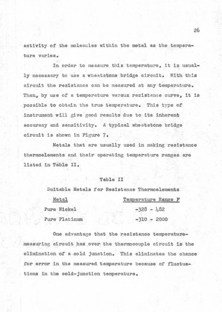
Metals that are usually used in making resistance
thermoelements and their operating temperature ranges are
listed in Table II
Table II
Suitable Metals for Resistance Thermoelements
Metal Temperature Range F
Pure Nickel -328 - 4-82
Pure Platinum -310 - 2000
One advantage that the resistance temperatureshy
measuring circuit has over the thermocouple circuit is the
elimination of a cold junction This eliminates the chance
for error in the measured temperature because of fluctuashy
tions in the cold-junction temperature
27
With the exception of the error due to the cold
junction the errors obtained in me asuring the temperature
by a thermocouple are the same as those for a resistance
thermoelement The fol lowing discussion therefore will be
applied only to the thermocouple It must be understood
however t hat the s ame discussion and mathematical formulas
may be used with the resistance t hermoelement
Four major factors tend to produce a difference
between the measured thermocouple temperature and the actual
temperature of a gas stream These four f actors are
1 Heat loss due to conduction along the thermoshycouple wires and well
2 Heat loss due to r adiation from the thermocouple junction to the cold walls
3 Heat gain due to radiation from t he gas to t he thermocouple
4 Heat gain due to a change in kinetic energy as the gas stream approaches the thermocouple
In this discussion each factor will be discussed individualshy
ly and then collectively
~~~ to Conduction
Since the main purpose of the thermocouple is to
measure the temperature of the gas stream accurately it is
necessary to determine whether or not the conduction loss
can be made negligible Jakob and Hawkins (8 p203) have
treated this subject very well They have found that the
error obtained in the temperature indicated by the
28
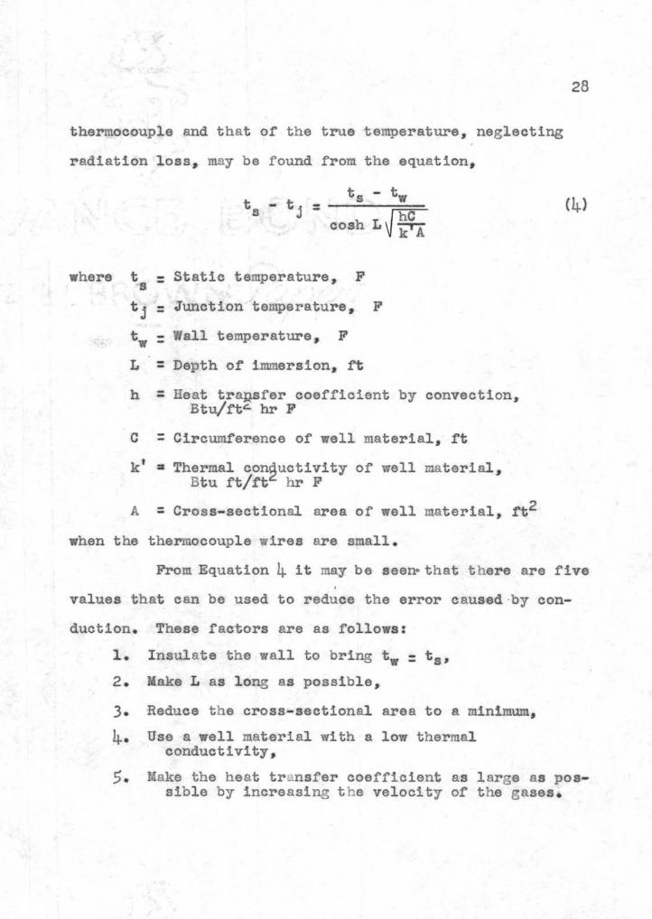
thermocouple and that of the true temperature neglecting
radiation loss may be found from the equationbull
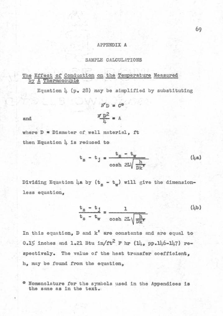
ts - tw ts- tj ----== lt4gt
cosh LWi
where t Static temperature F s -shytj - Junction temperature F-
Wall temperature F t = L Depth of immersion rt= h Heat tra~sfer coefficient by convection=
Btuft- hr F
c Circumference of well material ft= kt ~ Thermal con~uctivity of well material
Btu ftft hr F
A =Cross-sectional area of well material rt2
when the thermocouple wires are small
From Equation 4 it may be seenbull that t here are five
values that can be used to reduce the error caused middotby conshy
duction These factors are as follows
1 Insulate the wall to bring tw t 8
2 Make L as long as possible
3 Reduce the cross-sectional area to a minimum
4 Use a well material with a low t hermal conductivity
5 Make the he at transfer coefficient as large as posshysible by increasing t he velocity of t he gases
29
In view of these five factors it was decided that
the depth or immersion is the easiest to control With this
in mind a family of curves was plotted by using Equation 4 with the depth of immersion as the abscissa and the ratio of
t he temperatures as the ordinate This family of curves is
s hown in Figure 8
From these curves it can be seen that the error in
the thermocouple reading will be less than 1 per cent if the
thermocouple is i mmersed into the gas stream at least o6 inches It may be concluded therefore that if the thermoshy
couple is inunersed into the gas stream a distance of 06
inches or more the error produced will be negligible and
the thermocouple will g ive the true temperature
~ Loss ~ Radiation
Theoretically the heat loss due to radiation from
a hot body to a cold body is proportional to the difference
of the fourth powers of their respective absolute temperashy
tures If t his heat loss is set equal to the heat gain by
convection while assuming the conduction and velocity
effects a s being negligible there results an equation from
which the temperature of the gas can be calculated Th is
equation is as follows
(5)
rt bullmiddot +tshy
hmiddot
tt tt_ f+ 1_ _ middot 1_ bull middot
t ti rrrmiddot middot111 middot middot middot -shy
middot - -- - --middot _ = c_ - middot
L-t _ -_~ t_r t- middot~r
tf-7
I ~~ middot ~crt~~ rtn 11
i
$~
31
where At bull Area of the t hermocouple ft~
h =Heat transfer coefficient by convection Btutt2 hr F
ts Static temperature F
tj - Junction temperature F
tr = Stefan-Bolt~manp s radiation constant Btuhr ft RLlshy
6 bull Emissivity of the junction dimensionless
Tj =Junction temperature R
Tw bull Wall temperature R
It is often quite difficult~ however to measure the effecshy
tive wall temperature and it is much more difficult to deshy
termine the actual emissivity of the junction (5 pl52)
Therefore the method most commonly used to correct for
radiation is by some physical means This may be accomshy
plished either by shielding the thermocouple from the surshy
rounding cold walls by coaxial shields or by increasing the
wall temperature Since it is often quite difficult to
increase the wall temperature many investigators have deshy
vised various forms of shielding for the thermocouple
These shields tend to reduce the ability of the thermocouple
to follow fluctuating temperatures however and are quite
difficult to install
Another common method for reducing the radiation
loss is to use junctions of low emissivity As can be seen
from Equation 5 the heat loss by radiation is directly
32
proportional to the emissivity of the junction If this
emissivity is reduced the heat loss will be decreased and
the junction temperature will approach the true gas temperashy
ture A I Dahl and E F Flock have developed a junction
covered with silver in which the emissivity is reduced to
0 05 lt4 p l54) This reduced the heat loss to 1 16 of that
for a bare oxidized Ghromel - Alumel junction A comparison
or Chromel-Alumel thermocouples with different radiation
shields is given in Table III
Table III
Effectiveness of Radiation Shields (5 p 155) True Gas Temperature 1500 F Wall Temperature 1200 F
Shields
1 Coaxial 3 Coaxial Pressed Pressed None Tube Tubes Silver Platinum _ -
Indicated Ternperashy
ture F 14-32 1480 1494 Radiation Correcshytion P 68 20 lO 6 22
From Table III and from the curves shown in
Figure 9 it may be seen that the error in the indicated
temperature is less than 1 per cent Therefore in most
eases the indicated temperature may be assumed to be tha t of
the true static gas temperature
FIGURE 9
EFFECTS OF RADIATION ON THE TEMPERATURE MEASURED BY A SILVER-SHIELDED ~HERMOCOUPLE
Aa Computed from Equation 5a A
34
~ S Ez Radiation
The heat gain by the thermocouple due to radiation
from the gas stream is of relatively small value This is
especially true in g as streams in which the air-fuel ratio
is quite high In t h is installation t he air-fuel r atios are
in the order of 60 to 85 pounds of air per pound of fuel
This gives a combustion gas composition assuming co mplete
combustion as is shown in Table IV
Table IV
Variation of Combust i on Gas Composition
Range of Composition Combustion Gases by Volume
Carbon Dioxide 35 - 25 Water Vapor Oxygen Nitrogen
29 - 20 158- 175 778 - 780
It can be seen from Table IV that the amounts of
nonradiating gases oxygen and nitrogen are many times that
of t he radiating g ases c arbon dioxide and water vapor
(13 p64) therefore the emissivity of the total g as
stream would be extremely small and the heat gain by radiashy
tion from the gases can be assumed to be negligible
If t he thermocouples are placed in such a position
that they can see t h e fl ame then there may be a considershy
able heat gain due to radia tion since during combustion
35
there are higher concentrations of radiating gases and lower
concentrations of nonradiating gases
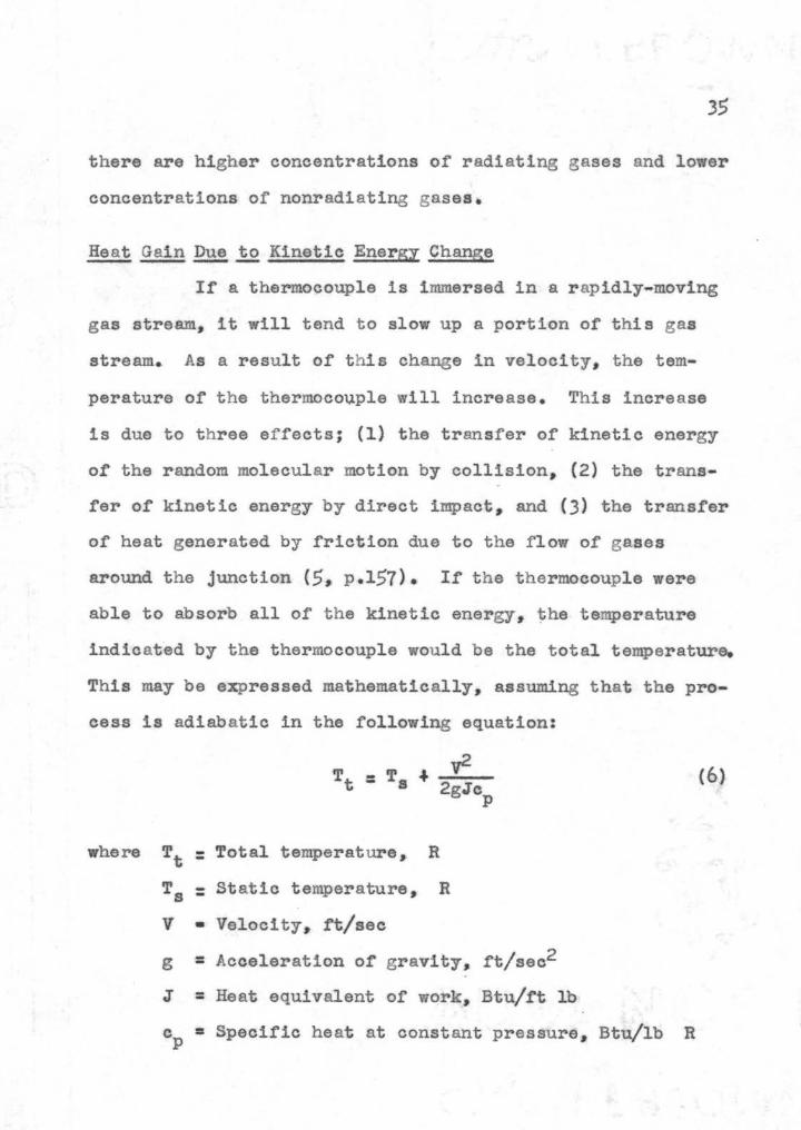
Heat ~~ to Kinetic Energy Change
If a thermocouple is immersed in a rapidly-moving
gas stream it will tend to slow up a portion of this gas
stream As a result of this change in velocity the temshy
perature of the thermoco~ple will increase This increase
is due to three effects (1) the transfer of kinetic energy
oC the random molecular motion by collision (2) the transshy
fer of kinetic energy by direct impact and (3) the transfer
of heat generated by friction due to the flow of gases
around the junction (5 pl57) If the thermocouple were
able to absorb all of the kinetic energy~ ~he temperature
indicated by the thermocouple would be the total temperature
This may be expressed mathematically assuming that the proshy
cess is adiabatic in the following equation
v2Tt middot= Ts f (6)
2gJep
where - Total temperature RTt -Ts -- Static temperature R
V bull Velocity ftsec
g Acceleration of gravity ftsec2
J =Heat equivalent of work Btuft lb
cp =Specific heat at constant pressure Btulb R
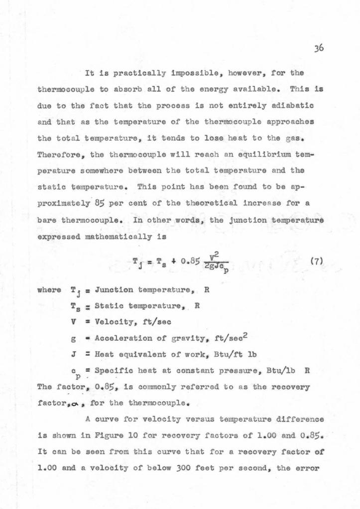
It is practically impossible however for the
thermocouple to absorb all of the energy available This is
due to the ~act that the process is not entirely adiabatic
and that as the temperature of the thermocouple approaches
the total temperature it tends to lose heat to the gas
Therefore the thermocouple will reach an equilibrium temshy
perature somewhere between the total temperature and the
static temperature This point has been found to be apshy
proximately 85 per cent of the theoretical increa se for a
bare thermocouple In other words the junction temperature
expressed mathematically is
(7)
where Tj - Junction temperature R-ls - Static temperature R
v Velocity rtsec
g bull Acceleration of gravity ftsec2
J -- Heat equivalent of work Bturt lb
c =Specific heat at constant pressure~ Btulb R p
The factor 085 is commonly referred to as the recovery
ractor o for the thermocouple bull
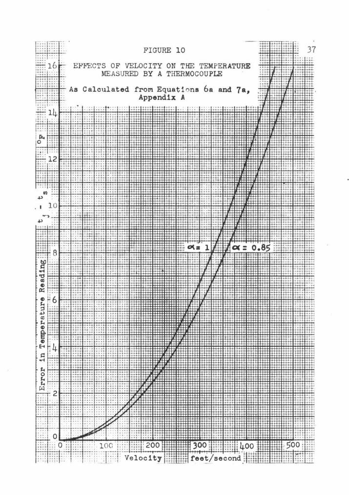
A curve for velocity versus temperature difference
is shown in Figure 10 for recovery factors of 100 and 085 It can be seen from this curve that for a recovery factor of
100 and a velocity of below 300 feet per second the error
m~um-T ~~- FIGURE 10 l I
~ 16 ~ EIltFECTS OF VELOCITY ON THE TEMPERATURE ~ middot MEASURED BY A THERMOCOUPLE 1-Hti 11 -t~ _j t ~r-r ITt -t- As Calculated from Equati ons 6a and 7a 77 ~~ ~ Appendix A ~-t
-
Lltt lfi 37
J j
1
tj
1 l
I l
- tJ~ ~ 500 [ gn tctfl q ~ rr~
38
in the true static temperature is less than l per cent
Therefore for this velocity and below the measured temshy
perature may be assumed to be that of the static temperature
Above this velocity the error increases rapidly for a small
change in velocity
In the above discussion each effect was considered
separately Now they will be considered together If a
heat balance is written for a thermocouple in equilibrium
it will be noticed that the heat transferred by convection
from the gas stream to the thermocouple plus the heat transshy
ferred by radiation from the gas stream to the thermocouple
plus t he heat transferred by the change in kinetic energy of
the gas stream must equal the heat lost by radiation from
the thermocouple to the cold walls plus the heat lost by
conduction along the thermocouple wires and well If the
heat loss due to conduction and the heat gain due to gas
radiation are negligible then the effect of the kinetic
energy change tends to offset the effect of radiation on the
thermocouple junction temperature This is only true howshy
ever for gas velocities below 400 feet per second and for a
silver-shielded thermocouple with a recovery factor of 085
or less The temperature indicated on t he measuring instrushy
ment below t his velocity may then be assumed to be essentialshy
ly the true static temperature
39
CONSTRUCTION AND PLACEflampN~ OF PYROMETERS AND EQUIPimNT
SilverShielded Thermocouple
Since the previous thermocouple installation alshy
lowed the thermocouples to ttsee the flame and since they
were placed in the section of highest velocity it was debull
cided that it would be better to place the new thermocouples
in an area of lower velocity end in a position where they
could not see-If the flame The three thermocouples at the
turb-ine inlet therefore were placed 120 degrees apart
around the turbine casing with the silver shield of the
thermocouple about 12 inch upstream from the nozzle ring
and directly opposite the nozzle inlets The three thermoshy
couples at the turbine ex~aust were placed directly opposite
the thermocouples at the turbine inlet and about 1-12
inches downstream from the turbine wheel blades
The thermocouples were madmiddote of No 20 Chromelshy
Alumel thermocouple lead wire A section of the wire was
cut off to the desired length depending upon whether the
thermocouple was to be used in the inlet casing or in the
exhaust casing - The lengths required are 8 inches for the
turbine inlet temperature and 5 inches f or the turbine exshy
haust temperature
The thermocouple bead was formed by twisting the
two wires together for a distance of 12 inch The ttlisted
portion was then heated in a neutral acetylene flame until
both wires glowed bright red The wires were then dipped
into bronzing flux until a good coating was formed The
flux- coated ends were immediately placed into the flame
until the bead formed After the wires cooled the flux
was broken off and the wires and bead were cleaned with
a wire brush
The silver shield was made from a tube 1 8 inch in
diameter and with a wall thickness of 0 020 inches This
silver tube was cut into 1 2- inch lengths Eaeh length was
slipped over a thermocouple bead until the bead was halfWay
into the shield The shield was then pressed tightly on the
thermocouple wires and bead The tighter the silver is
pressed on the bead the better the heat transfer is between
them After the shields were pressed on the beads the
ceramic insulators were slipped over the thermocouple wires
The terminal strip and individual connectors were
all made of fiberboard The terminal strip contains enough
terminals for twelve thermocouples and was used to join the
Chromel- Alumel lead wires to the copper wires of the switch
Each connector contains two brass cylinders into which the
thermocouple wires and the lead wires were placed These
wires were then clamped into place by set screws
Since the thermocouples at the turbine inlet were
to be placed in the turbine casing it was necessary to
construct a thermocouple support These supports were made
of 7 16- inch hexagonal head mach ine bolts (the heads of
which were ground to fit t he ca sing) These machine bolts
were t h en drilled with a 732- inch drill to provide the
necessary opening to f acilitate t he installation and removal
of the thermocouple Due to the curvature of t h e casing ~ it
was necessary to grind a s pa cer to fit closely to the outshy
side of the ca sing in order to prevent gas leakage around
t he supporting bolt A hexagonal he ad machine nut was used
to hold the assembly in place A bushing drilled out to
0 15 inches for the ceramic insulator was used to hold the
thermocouple in its support An exploded view of the
t hermocouple and its support is shown in Figuremiddot 11 and a
t ypical assembly drawing is shown in Figure 12
The supports for t he exhaust t h ermocouples were
made of 14- inch brass machine screws These screws were
held in place by a l4- inch hexagonal head machi ne nut A
0 152- inch hole was drilled longitudinally through t he bolt
for the ceramic insulators on the thermocouple
Resistance Thermoelement
The resistance thermoelement was to be made by
coiling the resistance wire in the form of a loop approxibull
mately 12 inches in diamter and passing it in front of the
entire circumference of the nozzle ring It was believmiddoted
that by doing t h is t he actual average temperature of the
FIGURE 11 EXPLODED VIEW OF THERMOCOUPLE AND ITS SUPPORT 1 Support bolt 2 Sp acer 3 Connector and connector bracket4 Spacer 5 Hexagonal head nut 6 Thermocouple bushing 7 S ilver-shielded thermocouple
3
Thernocou~ le S ~1pp o - t Bo lt
Nozzle Ring -~
Thermoc ounle Wires
Bushing
~-+~ Porcelain Insulator
F JEE 12 TYPICAL ASSEMBLY OF
~ ~ERMOCOU PLE AND SUPPORT
gases passing through the nozzles could be obtained This
is due tc the fact that the variation of the mass flow
across the entrance to the nozzle section is at a minimum
In other words the velocity of the gases entering the
nozzle will not vary substantially from the bottom of the
nozzle to the top of the nozzle- The materials from whieh
these thermoelements were to be made were No 20 Chr-omax
wire arid No 22 Ineonel wire The coils were to be supported
by insulators fastened to bolts extending down through the
thermocouple supports The exhaust thermoelement was to be
constructed and supported in a similar manner
The support for the thermoelement to be used in
the preliminary tests to determine the suitability of the
wire to t emperature measurement was made from a heater eleshy
ment core similar to that used in the ordinary household
electric heater Three feet of VIire was wrapped -on this
porcelain core and two copper leads of No 10 wire were
fastened to each end of the thennoelement
Pressure Probe Section
The pressure probe seetion was made of l - inch steel
plate with an 8 x 4- 5 16- inch elliptical opening A photoshy
graph of this section is shown in Figure 13 The pressure
probes were made from No 321 stainless steel tubing
18- inch in diameter with a wall thickness of 0 020 inches~
45
46
There were three total and two static pressure probes a-cross
the horizontal and vertical dimensions Each pzrobe was
located in the center of an area equal to onebullthird of the
total area of the opening The entire unit is located in
the transition section between the combustion chamber and
the turbin~ casing
Ihe purpose oi this pressure probe section was
to determine the velocity of the gases as they leave the
combustion chamber Sinee this section has the smallest
cross-sectional area and the highest weight now the veshy
locity at this point will be higher than at any point in
the turbine casing This is due to the fact that as soon
as the ga ses enter the combustion chamber a portion of the
gas leaves the chamber through the nozzles This gives a
varying weight flow around the entire turbine casing
Therefore if the velocity at the elliptical section is not
appreciable the yelocity at any other point in the easing
Vlll be lower and it will aTect the temperature indicated
by the thermocouple very little
I
47
TESTS
Apparatus
The apparatus other than the g as turbine used in
t he thermocouple tests can be divided into two groups
(1) t h e e quipment for temperature measurements and (2) the
equipment for other measurements The equipment contained
in the first group is as follows
l The silver-shielded t hermocouple
2 Cold-junction thermocouple
3 Twelve-point switch
4 Englehard millivoltmeter
The other equipment may be listed according to the values
measured as follows
1 Air flow - Ellison draft gage c ap acity 6 in water
2 Fuel rate - Toledo Seales and stop watch
Velocity pressure - Mariam water manometer capacity 60 in water
4shy Static pressure - Mariam mercury manometer capacity 14 in mercury
The electrical circuit for the thermocouple is
shown in Figure 14 This circuit contains t he t hermocouples
terminal strip 12-point switch and the millivoltmeter It
may be noticed from Figure 14 t h at the Chromel-Alumel lead
wires run only as far as t he terminal strip From t hat
point on t he wires are made of copper At first glance it
may seem that this would cause an error in t he readings but
48
Copper Wire--~------~
ChroMl Wire Alumel Wire
Cold Junction
FIGURE 14 ELECTRICAL CIRCUIT FOR THERMOCOUPLES
Rebull1bulltanee lbtlW)tliMDt
Wheatstone Bridge Potentiometer
FIGURE 15 ELECTRICAL CIRCUIT FOR RESI ST ANCE THERMOELEMENT
49
if the cold-junction Vires are connected to the copper wires
at the terminal strlp then all copper-Chromel and coppershy
Alumel junctions will be at the same temperature and no
error will occur 6 p 85)
The apparatus for the tests on the resistance
thermoelement can also be divided into two groups (1) the
equipment used in the preliminary tests and (2) the equipshy
ment which was to be used in the final tests The equipment
in Group 1 is listed as follows
1 The resistance thermoelement
2 Leeds and Northrup wheatstone bridge
3 arshall-Hall tubular furnace
4 Wbeelco controller and its thermocouple
5 Comparison Chromel-Alumel thermocouple
6 Leeds and Northrup potentiometer
The electrical connections for t h is equipment are shown in
Figure 15 The equipment contained in Group 2 is the same
as the equipment used in the thermocouple tests except that
in place of -the temperature- measuring e quipment the followshy
ing equipment was to be used
1 Resistance thermoelement
2 Leeds and Northrup wheatstone bridge
Procedure
The procedure used in conducting the test on the
thermocouples and the procedure which was to be used for th~
final test on the resistance thermoelement were similar
The original method of conducting the tests consisted of
bringing the turbine up to a definite speed and jockeying
the fuel control valve to maintain this speed~ After the
designated speed had been reached a series of readings of
all values were taken The fuel r ate was measured in seconds
per half-pound and was measured twice during each run
The values obtained from this test were quite
erratic _ Since it was necessary to constantly jockey the
fuel control valve t o maintain a derinite speed the conbull
ditions could never reach a static state Consequently
it was decided to revise the procedure by adjusting the
throttle once and letting the turbine reach its own speed
After this had been stabilized a series of readings were
taken as before The results obtained by this method were
more consistent_ so this procedure for controlling the turshy
bine speed was used
throughout the test A series of 8 to
10 readings each at a different turbine speed were taken
during each test
The procedure used in the thermocouple calibration
was the standard c alibration procedure This procedure conshy
sists of immersing the thermocouple into a bath of molten
pur-e metal and then recording the millivoltmeter readings as
the metal cools As the metal begins to solidiry_ its tem
perature will tend to remain constant fhe temperature
51
indicated by the thermocouple can be compared with the known
true freezing temperature of the metal These thermocouples
were calibrated at three points ~ the freezing point of water
the freezing point of pure lead ~ and the freezing point of
pure aluminum
rhe procedure used to determine the suitability of
Inconel wire and Nichrome wire for resistance thermoelements
was quite simple l The Wheelco temperature controller was
set for the desired temperature ranging from 0 F to 1850 F
When the controller indicated this desired temperature a
series of readings were taken for the resistance of the
thermoelement and for the temperature of the comparison
thermocouple These readings were taken every 30 seconds
until three readings of constant value were reco~ded The
controller temperature was then increased approximately
166 F This temperature interval gave a total of thirteen
test points
1 The Nichrome wire test was added at the last minute since the Chromax wire did not arrive in time to be testedbull
52
RESULTS
The results of the calibration tests on the
silver-shielded and bare thermocouples are shown in Appenshy
dix B A calibration curve was not drawn since the dlfbull
ferenee between the true temper-ature and the indicated tem
perature for both t ypes was quite small--less than 15
per cent Since this difference was so smallj the indicated
temperature was assumed to be the true temperature It was
also assumed that since t he twelve thermocouples calibrated
were not in error by more than 15 per cent~ any other
thermocouple made from the same sample of wimiddotre and in the
same way would not have a greater error The calibration
data also indicates that the silver shield does not have a
noticeable effeet on t he thermocouple reading since both
types of t hermocouples had the same range of inaccuracy
It was quite cUffleult to obtain the calibration
for the silver-shielded thermocouples at the freezing point
of aluminum since the melting point of silver is only a rew
hundred degrees higher than that of aluminum Consequently
extreme care had to be taken to prevent excessive super
heating of the aluminum before the silver-shielded thermoshy
couple was immersed in the bath of molten metal
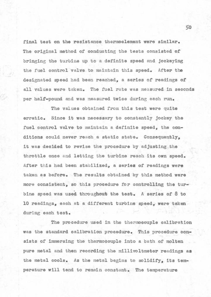
The results of the tests on the silver-shielded
thermocouples are shown in Figure 16 A test using bate
thermocouples instead or the silver shielded thermocouples
bull bull bull bull
53
FIGURE l6
TEMPERATURES AS MEASURED BY THE SILVER-SHIELDED THERMOCOUPLE
bull -+middot
- ~fl-l-J i jU
Temperature ~-+- f-1- Lh ~ -- - ~ ~h-bull-bull+- Itt shy
--- --Jl --- -middot bullbullbull_ ~ middot middot middot Lmiddot
Av~rage Exhaust Tempe_rat_ure ~-- 1100 -shymiddot-middot ~- ----E ~ ~~ ~= -t=-t~
~middot --- middot _ ~ shy
middot middot
~
middot-
bull T bull bull bull-shy o bull bull bull bull -~ middot- bull _ middotmiddot-middot -middot bull ~ - ~
t-Jshy
-shy
_ 1 ~ -- ~~ middot middotmiddot middot~
+--shy middot-middotshy middot ~ _-~~
-r- bull
54
was made in order to draw a comparison between the two
The results from the bare thermocouple test are shown in
Figure 17 with a comparison of the average turbine inlet
temperatures as measured by t hese two methods appe aring in
Figure 18
The turbine was stopped after four runs were comshy
pleted in the test on the silver-shielded thermocouples and
each of the silver shields on the turbine inlet t hermoshy
couples were inspected for signs of deterioration The
shields on t he two top thermocouples Nos 1 and 2 did not
show any signs of having been subjected to high temperashy
tures The shield on Thermocouple 3 however which is
located at the bottom of the t urbine casing was burned off
Another silver-shielded t hermocouple was substituted for it
during the remainder of the test The exhaust thermocouple
shields were found to be without signs of deterioration
The shields on all or the t hermocouples were
inspected again at the end of t he test and again the
silver sh ield on Thermocouple 3 was burned orr This meant
t hat at some t ime during t he testing period the gases were
at a temperature greater than t he melting point of silver
1762 F This period was probably during the first few minshy
utes after the turbine had started and while the air-fuel
ratio was still considerably below the normal operating
range of 72 to 82 pounds of air per pound of fuel It was
55
bull bull l middot- ~ __ bullbullt-- middotmiddot--middot ~- ~- middot -h middot - tn middot ~ --=tn- -middot shymiddotmiddot~ ~-middotmiddot 1- middot FIGURE 17i -1t~~r- rttt +t= ~w -middot-
AS MEASURED 3Y THE BARE THERMOCOUPLFS
IplusmnT- Jp bull bull ~ t----t-t-1 11---
middot--~ --middotmiddotmiddotmiddot middot TEMPERATURE
bull tTttr
Average Inlet Temperature ~ -T 1
~ - 1-- t f-JS~ 1100 ~
middotmiddot ~ 1-
56
Thermocouple
FIGURE 18
COMPARISON OF AVERAGE INLET TEMPERATURES AS MEASURED BY A SILVER-SHIELDED AND
A BARE THERMOCOUPLE
I Bare Therm~oo~ ~le
1000
~~ine Wall Temp~rature
78 80
lbs or airlb of fuel
82
57
apparently impossible to keep a silver shield on Thermo
couple 3 so the indicated temperature was used in finding
the average turbine inlet temperature used in Figure 16
The temperature indicated by Thermocouple 3
whether it had a silver shield or not was always several
hundred degrees higher than the temperature indicated by
Thermocouples 1 and 2 located in the upper portion of the
turbine casing Thus the hottest gases pass through the
bottom of the turbine casing rather t han through the top
This is often illustrated by flame shooting through the turshy
bine wheel blades during either t he starting cycle or during
rapid acceleration
A check on the maximum velocity in the turbine was
obtained at the elliptical section by computation and it
was found to be not greater than 390 feet per second It
was therefore deened unnecessary to apply a velocity corshy
rection to the thermocouple readings since the velocity was
still below 400 feet per second The actual velocity of the
gas around the thermocouples would be less than the velocity
at the elliptical section due to the gases leaving the turshy
bine casing through t he nozzle ring
It can be noticed in Figures 16 and 17 that the
average turbine exhaust temperature is below that of the
average turbine inlet temperature Up until this time the
measured turbine eXhaust temperature had always been greater
58
than the measured inlet temperature a condition which
theoretically and physically can not be
Figures 16 and 17 also show that the average turshy
bine inlet temperature is considerably higher than the
theoretical inlet temperature This might be due to some
phenomenon occuring during the combustion of the fuel It
was quite evident during the tests that something middotwas wrong
with the combustion since large amounts of blue smoke issued
from the exhaust ring This smoke contained compounds which
were irritating to the eyes causing tears to form During
complete combustion these irritating compounds are not
noticeable in the exhaust gases
Figure 18 shows a comparison of the average inlet
turbine temperature measured by the silver- shielded and bare
thermocouples It can be noticed that as the wall temperashy
ture and air~fuel ratio increase the difference between the
temperatures indicated by the two thermocouples decreases
This is due to the decrease in the radiation loss by the
bare thermocouple and an increase in the heat transfer
coefficient by convection caused by an increase in velocity
of the gases
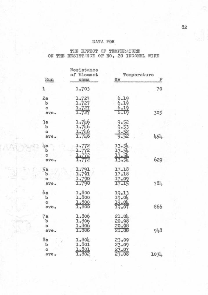
The results from the preliminary test on No 20
Inconel wire are shown in Figure 19 A preliminary test on
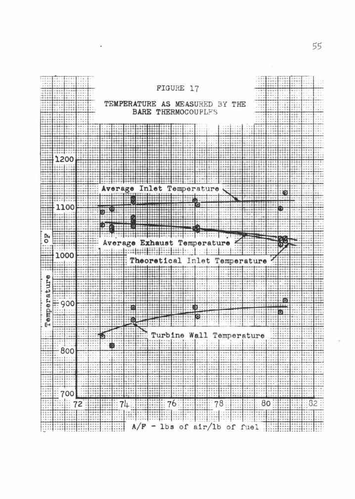
a sample of Nichrome wire taken from a heater element waa
also conducted and the results are shown in Figure 20
bull bull
bullbullbullbullbull bull
I~~-- ~ --~ middotT-- i I I ~- -r -middot I
JIGURE 19 -+--jf- - t--t--f- t -~ --shy -shy - middotmiddot 1-~a4 ~-~ -- - -__~= - middot THE EFFECT OF TEMPERATURE ON THB middot middot middotmiddot middot middot middot middot middot middot middot middotmiddot middot 1t-middotr-rmiddot-- r-- ~ - r+ RESISTANCE OF NO 20 INCONEL WIRE bull bullbull bull i
i middot I - -+----+--+ - -r----17 middot middot I
11
182 ~ - ~~middot _~~ middot middotmiddot= middot middot middot middot middot middotmiddot -=====middot== middot = === middotmiddot= ~_-+i_ middot--~--~-~~-f~middot ~~ ~~~ middotmiddot _-middotL~=middotmiddot=====middot middot middot == middot ~= middot middotmiddot==== middotmiddot=~ middot - -~~ t ~ _ _j_ ___ r--~ --T-- --- middot ~ middot bull ~ 1 -JI~ - c I I bullbull l~middot ~ middot ~middot i middot bullmiddot ~ 1~ middot
I t middot middotmiddotmiddotmiddot bull ~ _ ~ middot t---bullmiddotmiddotmiddotmiddotmiddotmiddot middotmiddotbullmiddotmiddot middotmiddotmiddotmiddotmiddotmiddotmiddot ~rfitll
ll 0 _middot I middot - t middot rr~ i ~ r 1 + bull ioo middot bullbull ~ ~ + I ~ ~ ~tl - ~ ~ I
~~ ~~ middot-- middot -r-- 1 ___bull_ ~ middot middotmiddot11-l lltt bull ~ middot r --- ~- - imiddot _ ~ _ bullbull ~ - 1 ~middot middotmiddotmiddotmiddot bullbull ~ bullbullbullbull J bull
jmiddot middot middot middot middot middot 1-4 h+ ~ ~-+- fri ~ rmiddot middot middot middot +I~ middot middot middot middot middotmiddot middot middot middot middot middot middot middot i middot ~ -~ e ~1 middot t middot middot middot middot middot _L +
f - I middot middot Jiotmiddot bull middot bullbull ~~t =t=r middot~ -middot bull -middot ltmiddot 7-- -if-middotplusmnplusmnl middot - I ~ _ ~ bull bull bullbull bull bull t bull bullbullbull j bull bullbull bull bull bull bullbull bull 1 o
t 17l middot v i middot I I I I-~--~~~ n~ _ ___ ---middotH middot - ---- ---~~ _ middot - --- middotmiddot middot __ ____r--+---L__ --~-middot I middot
middotmiddot middot t II Ibull ~middot I I I
174 middot ~+ ~- middot ----L-- I middot ~ l -~--- - ~L-~ --4~ - - --- ___ _ ___ r----~ -- middot- middot-~--- ----i- __L_r___i ___ ~~ - ~--_ -- bull v middot I I middot ~middot If___ _j__ -- middotI I I --h----1-------r-- _ 1 I
I I_ I I I iI I
I -- i-Gvr middot-middot-t---r---- -~----- middotl-- ~--- ~--- ~-- --+- lshy i ~ 170 r---L middot middot middot middotmiddotmiddot 1 middot middot middot middot middot middot middot middot --~ ~---- ---+-~
middot I II I
I bull I I
~l - middot -- ---~-middot - -middot~--f--middot- -- -- --~ t--1--~ middot~ I I I If~ ~ bull bull bull ~ bull bull bull bull bull bull bull 1l bull bull bull bull bull bull bull bull bull bull t Ibull I bull
I bull bull i t i 0
I ~~ I li i I -~-- - middot r middotmiddot middotbullmiddotmiddot bull t ---- ~ -- il --~ -- - -~ __ ~ r-- middot I t l t I T bullbull bull
bull middot bull middot middot middot middot bull bull middot bull bull bull bull bull bull bull It I t1 66 1 bull ( middot 200 1 bull bull 4oo middotmiddot middot middot 6oo Boo bull bull i 1ooo i middotbull 1200 middot 14oo middot 16uo
1
L- ~ - r l l t -- ~ - r middot~ r Jr~~p~~~t~~ettt middot ~r Imiddot- middot F1middot1 T--r--- L~
61
It can be seen in Figure 19 that there is a
definite dip in the resistance versus temperature curve bull
bullAt first it was believed that this dip was caused by the
fact that the wire was slightly hardened by cold- working
while it was being wrapped on the porcelain core This
hardening would tend to increase its resistance As the
annealing range for Inconel wire was approachedbull this
hardening would be relieved with the result that the resistshy
ance decreased slightly However after annealing the
wire another test was made and an identical curve was
obtained
Because of this dip it would make it extremely
difficult to measure a temperature between 800 and 1600 F
since for any given resistance between 1 795 and 1 8o6 there
are several corresponding temperatures~ This fact alone
makes the use of Inconel wire unsuitable for a resist ance
thermoelement above temperatures of Boo F Due t middoto this
characteristic the tests on Inconel wire were discontinued
It can be seen from Figure 20 that the Nichrome
wire s resistance versus temperature curve did not produce
a dip in the curve as did the Inconel wire However the
increa se in the resistance with temperature of the wire
above 1000 F becomes very small- -in the order of 0 00045
ohms F This low value of the thermal coefficient of
resistance would then require a very sensitive instrument
bull
62
in order to measure the increase in resistance In fact
it would be almost impossible to use a manually-balanced
middot wheatstone bridge to measure the resistance of the eletnent
if the element were placed in a varying- temperature gas
stream An automatic b~lancing bridge could probably be
used with some degree of accura cy but since this type of
instrument was not available the use of a Nichrome wire
from a h~ater element as a resistance thermoelement was
discontinued
CONCLUSIONS
From the results of the tests on the silvershy
shielded thermocouples_ it may be concluded that this type
of temperature-meas~ng device does have the qualities for
measuring the temperatures of high-temperature gas streams
if the gas stream temperature does not fluctuate above the
melting point of silver This is the main factor which
would prevent its use in the Ore gon State College ga s turshy
bine The constant replacing of the silver shield on just
one thermocouple would soon become not only expensive but
also time-consuming Even if the expense were considered to
be negligible the fact that the shield burns off during the
starting cycle and before any test runs can be made defeats
the purpose of the shield and a bare thermocouple might as
well be used
It was interesting to note that a temperature drop
was measured across the turbine by both the silver-shieldad
middot thermocouples and the bare thermocouples This was unshy
doubtedly due to better placement of the thermocouples with
the result that fewer temperature- measuring errors were
involved
The poor characteristicmiddots of resistance versus
temperature for Inconel wire in the temperature range of
800 to 1600 F makes it prohibitive for use as a resistance
thermoelement material within this temperature range It
might however prove to be a good material for measuring
temperatures below 800 F
lhe Nichrome wire from a heater element is unsuit shy
able for this installation since it has a very low lnerease
in resistance with tempera ture between 1000 and 1300 P
Between 1100 and 1300 F the thermal coefficient of resistshy
ance is 0 00045 ohms F Consequently any change in the
resistance of the lead wires would give a sizable error in
the measured resistance
65
RECOMMENDATIONS FOR FUTURE INVESTIGATIONS
Since none or the pyrometers selected ~or testing
were suitable for use in the gas turbine installation the
recommendations for fUture investigations of types of pyromshy
eters to be tested are as follows
1 Investigate the suitability of either the sonic
pyrometer or one of the pneumatic pyrometers
with a tube into which a sample of gas may be
drawn from several points across the turbine
easing This tube should be of such size that
the weight flow within the tube is a small pershy
centage of the total weight flow
2 Investigate the suitability of Chromax wire aa
a resistance thermoelement It is believed that
the resistance of the wire increases approximately
4 per cent between 1000 and 1400 F This increase
would be a small quantity but 1t could be
measured easily enough This investigation
might include whether it can be used in an oxibull
dizing atmosphere whether it can be accurately
reproduced and whether its resistance versUJI
temperature properties change with use bull
3 Investigate the possibilities of using Alumel
wire as a resistance thermoelement This wire
is used mostly for thermocouples but it does
66
middothave a high thermal coefficient of resistance
an4 may prove to be a good material for reshy
sistance thermoelements
4-bull Install three platinum resistance thermoele
menta in the present turbine inlet thermoshy
couple installations The cost ot one plati
num resistance element enclosed in an 18- 8
stainless steel tube 6 inches long is approxishy
mately $36 It is realized that this is quite
eJtpens1ve but it is believed that this inshy
strument will give the best results since it
has a very high thermal coefficLent of resistshy
ance 4shy
BIBLIOGRAPHY
1~ Beebe H M and c R Droms A simplified thenmoshycouple for temperature measurement in high velocity gas stream Instruments 24338-341 1951
2 Burgess G K and H LeChatelier Measurements of higp temperatures 2nd ed N Y~ Wiley 1904 34lp
Clark J A and w M Rohsenow New method for deshytermining the static temperature of a high-veloci~ gas stream Transactions of the American society of mechanical engineers 74219-227 1952
Dahl A I and E F Flock Shielded thermocouple for gas turbines Transactions of the American society of mechanical engineers 71153-160 1949
Flock E F and A I Dahl The use of thermocouples in high velocity gas streams The journal of the society of naval engineers 60139-161 May 1948
6 Foote P D c o Fairchild and T R Harrison Pyrometric practice technologic papers of the bureau of standards Washington D c Governshyment Printing Office 1921 326p
Griswold John Fuels combustion and furnaces NY McGraw-Hill 1946 PPbull74-135bull
8 Jakob Max and George A Hawkins Heat transfer and insulation 2nd ed N Y Wiley 1950 pp202-208
9bull Johnson A J and G H Auth Fuels and combustion handbook NY McGraw- Hill 1951 915p
10 Keenan Joseph H and Joseph Kaye Gas tables thermoshydynamic properties of air properties of combusshytion and component gases~ compressible flow funcshytions N Y Wiley 1950 pp l-128
11 King w J Measurements of high temperature in highshyvelocity gas streams Transactions of the Amerishycan society of mechanical engineers 65421-425 1943middot
68
12 Lloyd P Determination of g as turbine combustion chamber efficiency by chemical means Transshyactions of the American society of mechanical engineers 70335-341 1948
13 McAdams W H He at transmission 2nd ed NY McGraw-Hill 1942 459Pbull
Michaelson H B Ceramic materials for industrial and electrical use Product engineering 22145-151 July 1951
Moore D w A pneumatic method for measuring highshytemperature gases Aeronautical engineering review 730-4 May 1948
16 Severinghaus W L Reducing radiation errors in gas temperature measurement Mechanical engineering 59 334middot 1937
17 Walsh E P Sidney Allen and J R Hamm A pyromshyeter for measuring total temperatures in low density gas streams Transactions of the American society of mechanical engineers 72851shy858 1950
18 Wood w P and J M Cork Pyrometry NY McGrawshyHill 1946 PPbull74-135
APPENDICES
~
APPENDIX A
SAMPLE CALCULATIONS
The Effect of Conduction ~ the Temperature Measured bz Thermocouple
Equation 4 (p 28) may be simplified by substituting
and
where D bull Diameter of wmiddotell material ft
then Equation 4 is reduced to
C4a)
Dividing Equation 4a by (t8
- tw will give the dimensionshy
less equation
ts - tj = ___1_-=~ ts- t h 2L~ cos ~ Dkshy
In this equa tion D and k are constants and are equal to
015 inches and 121 Btu intt2 F hr 14 ppJ46-l47) reshy
spectively The value of the heat transfer coefficient
h may be found from the equation
Nomenclature for the symbols used in the Appendices is the same as in the textr
70
_ (k ~(GlD) 057h- 03 g shyD P g
where A bull Dynamic viscosity of the gas lbft2 hr g
and where k and A (10 p34) are taken as that of air at g g a temperature corresponding to Ts- Tw- bull
2
Assuming that
Ts + Tw = 1400 R 2
and that Gl 1oooo 1brt2 hr
the heat transfer coefficient is
0 h (0~3) fOo B) (( 10 OOOA (00125)) -57
0 012 o 71
=525 Btuft2 hr F
Then as-suming that the heat transfer coefficient h is
equal to 100 Btuhr ft 2 F and that the depth of i~~ersion t 8 - tjL is equal to 030 inches the ratio of shyts - tw
may be found from Equation 4b
ts - t l =-------1===~===shyts - tw cosh 2(0025) ~ OOl~5ftf21)
= 00345
71
The Effect poundpound Radiation ~~ Temperature Measured ~ Silver-Shielded Thermocouple
Solving Equation 5 (p 29) for (ts - tj) the following
equation is formed
(5a)
In this equation ~ is equal to 0174 x 10-8 Btuhr ft2
and assuming that the silver shield has an effective
emissivity of 005 then only the heat transfer coefficient
h and the difference of the absolute temperatures will
vary Then assuming that h bull 100 Btuhr rt2 F and
the error in the thermocouple reading as calculated from
Equation 5a is
0174)005)(50000)ts - tj bull 1oo
=43 F
72
8
The Effect EI Velocity 21 1h2 Temperature Measured Ez JThermocouple
Solving Equations 6 and 7 (pp35 and 36) for (Tj- T )
the following equations are rormed
v2T T (6a)
j - s = 2gJcp
T T 08$ v2 (a)- s --middot 2gJcJ p
Then assuming a mean value for c p a 0267 (10 p34) the
error in the thermocouple readings for a velocity of 300
feet per second for Equation 6a is
673 F
and for Equation a is
=571 F
Since the difference between the absolute temperatures is equal to the difference between the temperature in F t j - ts can be substituted for T j T
8 o
73
~Turbines Theoretical Inlet Temperature
The heat balance for the combustion chamber based on
one pound of fuel and assuming complete combustion and no
heat loss is as follows
lower heating value of the fuel minus latent
heat of vaporization plus heat content or the entering air equals heat content of the
combustion gases
The lower heating value of the fuel is found as follows
BRV =Higher heating value
LHV bull Lower heating value
(9)
where hrg heat of vaporization of water at 60 F
The per cent by weight of hydrogen in the fuel may be
found by the equation
= f 24-5 ) - f 194 3 - 86 (10) sp gr6o6o sp gr6060)(K))
where sp gr60 60 =specific gravity at 60 F
K =characterization factor of the fuel oil (7 p93)
74
Then from tests on t he fuel oil the require values were
found to be as follows
gravity bull 31 9 API at 60 F
specific gravity =0 866 at 60 F
kinematic viscosity at 100 F ~ 3 5 centistokes
viscosity bull 375 SSU at 100 F
Using these values the characterization factor~ K may be
found from curves of characterization factor and viscosity
at 100 F (7 p91) for t his fuel K =115
Then using Equation 10 t he percent age of hydrogen is
=12 27
Using this value for hydro gen in Equation 8 the higher
heating value is
HHV =323 5(12 27) f 15410
19370 Btulb
and the lower heating value is
LHV _ (12 27) (9)(1060) 19 370 100
=18200 Btulb
75
The latent heat
equation
or vaporization may be found from the
(11)
where L =latent heat of vaporization Btulb
d = specific gravity 6060
t bull temperature F (9 p210)
Assuming t bull 60 F the latent heat of vaporization is
L = 6sect66 ~109 shy oo9c6o~
122 Btulb
The heat content of the incoming air is
(12)
where f =air-fuel ratio lbs of airlb of fUel
ted compressor discharge temperature F
Then assuming
and
f =70 lbs of airlb of fuel
ted =100 F
Btulb =024(70) (100 - 60) middot
= 671 Btulb
76
The h eat content of combustion gases is as follows
Combustion gases assuming f = 70 lbs of airlb of fuel
Combustion Gas lb moleslb fuel
co 00732 H 0 0061
2
02 0403
1910N2
The heat content of combustion gas is
(13)
where m = combustion gas 1b moleslb fuel
- enthalpy of gas at temperature t Btulb mole~ -enthalpy of gas at 6o F Btulb moleh6o shy-
Assuming t 1100 F
Btulb (C02 ) -- 0073(15325 3880) -- 835
Btu1b (H20) -- 0061 ( 13115 ljl22) -- 548
Btulb (02) =o403(llSo5 3606) -- 3180
Btulb (N2) -- 1910(11104 3611) =14300
Total 18863 Btulb
Using the velue from Equation 13 with the values from
Equations 9 11 and 12 the heat balance is
18200 - 122 f 671 18863
18749 J 18863
77
Slncmiddote this heat balance does n~t agree a new temperashy
ture t bull in Equation 13 must be assumed and the calculations
for heat content in the exhaust gases repeated When the t wo
values in the heat balance agree temperature t bull is the
turbines theoretical inlet temperature A family of curves
for the theoretical temperature versus airmiddotfuel ratio is
shown in Figure 2lo
~
APPENDIX B
DATA FOR
SILVER-SHIELDED THERMOCOUPLES
rpm x lo-3 8 9 10 108 118 12-0 124 136 142 145
Inlet t 1 - F 1065 109A 1086 1099 1070 1099 1082 1099 1099 1091 t2 - F 998 101 1010 1062 1002 1023 1015 1023 1040 1032
p-lshyt - 12 0 1260 1282 ave t3 - F 11ftsect ~23 fm3 1l30 ~2 ll_27 1g 135 fm im7
t F 829 867 875 913 875 917 905 917 905 913 w
Exhaust t~ - F 1078 1087 1083 1103 1057 1087 1065 1070 1065 1065 t F 888 875 897 863 888 875 875 875 863 to - F ~ fsectRmiddot~-it 1320
88~ --ffil-22ave t F 1100 013 1093 9 1073 iyenot0 tm7 fm79 ~i~~ Theoretical t - F 1045 1020 1023 1041 1010 1035 1035 1030 1027 1032
F 106 112 125 134 136 151 152 170 174 176Ted -
Pn - in H2o 1 bull o5 155 173 203 240 252 275 331 345 373
wr bull sec1b 558 476 45~3 416 398 383 365 34~3 340 325 ~
middot ~ AF _ 1b of air 74-4 770 775 77 o 80 1 790 78 bull 7 810 820 81 5lb of fuel
Pv - in H2o 40 35 62 70 8 o 85 8 6 102 107 110
Silver shields burned ofr at start of runshy
-1i Values are in error due to switch not being adjusted correctly -()
DAT A FOR
BARE THERMOCOUPLES
rpm x 1omiddot3 9 9bull2 106 110 116 126 135 141
Inlet t 1 - F 1065 1065 1078 1099 10l5 108~ 10~7 1090 t2 F 955 917 9 8 96 9 0 976 9zo 994 t - F 128 1286
ave t3 F Tin TIl1~ ~ ~ ~ i8~ ii3~ t F 810 829 863 890 870 890 870 905w
Exhaust t4 F 1045 1048 1040 1080 100 10~0 1025 1000 F 835 845 850 870 8 0 8 5 830 835t5 shyF 1320t6 shy 12~~ pound25~ave t - F 2 yenoti 1070 ~ 0 0~ 3 7 ~ 3 ~3
Theoretical t - F 1058 1065 1060 1077 1052 1055 1021 1030
Ted - F 107 108 122 142 149 150 154 164
4 Pn - in H20 143 163 205 226 246 289 3 bull 42 370
wr - seclb 47middot4 44middot2 4oo 381 378 34~8 336 32amp3 AF 1b of air 735 731 74-4 74-4 771 770 806 80 8- lb of fuel Pv - in H2o 55 60 74 76 8middot 7 96 106 114
Q) 0
81
DATA FOR
CALIBRATION OF CHROMEL-ALUMEL THERMOCOUPLES
LEAD BATH
True Indicated Thermocouele l~o Temperature F Temperature F Error
(Bare)
i l middot 620 624 o65 2 620 622 038
620 615 0-81 620 620 ooo 620 620 ooo 620 61l 145
(Shielded)
1 620 62j o4a 2 620 62shy o~
l 620 616 o 5 ~ 620 621 o1o 620 619 016 620 612 129
ALUMINUM BATH
(Bare)
1 1217 02512ii
2 1217 121 ooa
1217 1222 o4J 1217 1214 025
6 1217 12~ 025 1217 121 008
(Shielded)
1 1217 1215 016 2 1217 1217 ooo
i 1217 1221 0361217 01 middot 121~1217 121 025 1217 121 ooa
82
DATA FOR
THE EFFECT OF TEMPERATURE ON TEE RESISTlNCE OF NO bull 20 INCONEL WIRE
Resistance of Element Temperature
Run ohms Mv F-1 1703 70
2-a 1727 619 b 1727 619 c 1727 ave 1727 secti~ 305
3a 1746 952 b 1746 953 c ave ~ ~7 454
4-a 1772 1354 b 1772 135 c ave ~middot77 ~bull 629
5a 1791 1718 b 1791 1718 c ave i1~sect i~~ 784
6a 1~800 191~ b 1800 190 c 1800 ave 1800 i~g~ 866
7a 1806 210~ b 1806 209 c 1806 ave 1806 sectyen6g 948
8a 1804 2309 b 1801 2309 c 1801 ave 180~ ~ 10343middot
83
Run-Resistance of Element
ohms Mv Temperature
F
9a b c ave
lOa b c ave middot
11a b c ave
12a b c ave
13a b c ave
l4a b middot c ave
1796 1796
~79
1797 1797
~ 1~798 1798
~bull79
1799 1799 1799 1799
1804 1804
~0
1822 1823
~3
2498 2498
~ 2715 2720
sect~isect 2911 2911
~9middot
3132 3132
~3 middot3
33-W+ 33-44
5~~ 3755 3755
~
1115
1210
1291
1385
1479
1660
84shy
DATA FOR
PRELUUNABY TEST ON NICHROME HEATER ELEMENT
Resistance of E1ellellt Temperature
Run ohms Mv F
1 1750 70
2a 1782 529 b 1782 529 c ave ~ ~1middot 265
)a 1818 856 b 1818 8 56 e 1818 ave 1818 ~~~ 411
4-a 1853 1209 b 1853 1209 c ave ig~~ ~bull 9 567
5a 1880 1574 b 1880 1574 e 1880 ave 1886 ~ 724shy
6a 1903 1967 b 1904 1967 c ave i~ampft ~9 892
7a 1919 2416 b 19bull 19 2416 c ave i~i~ ~kisect 1081
8a 19-26 2808 b 1926 2808 c ave i9 ~~ ~0 12469middot
9a 1946 35~76 b 19~47 3570 c ave ~7 ~7 1580
CHROMEL vs ALUMEL THERMOCOUPLES o_ flllrHhelt lefence Junction 11deg f
D P obull ~tobull
00 -58 1)2 60 -58 163
100 -47 174 15deg -S7 1135 200 -28 197 26v -15 208 3IP -01 220 350 07 231 400 18 243 450 29 254 5()0 40 266 ssO 51 277 600 52 289 650 73 300 70deg 64 312 75deg 95 324 ooo 11)6 336 650 117 348 goo 129 359 95deg 140 370
100deg 1)2 382 v per bullF 022 023
3oobull 400bull I H eoebull aooobull uoobull uoobull
II l 1 bull l bull bull bull t bull
3132 609 831 1056 1285 1518 17~ 19138 2225 2452 21398 2933 393 620 842 101) 1296 1529 17133 2000 2237 2474 210 2945 405 631 853 1079 1300 1541 1775 2012 2249 24135 221 2956 416 642 81$4 1090 1319 1552 171J7 20~ 22130 2497 2733 29138 428 653 878 U02 1331 1554 1799 2036 2272 2509 245 2979 439 6~ 8J7 1113 1343 1576 1810 2047 229-1 2521 257 2991 451 675 8Qfl 1126 356 161JB 1822 201)9 2296 2533 268 3002 4132 6136 91)9 11 ~ 1~57 1600 1834 2071 2300 2545 280 3014 474 618 920 1147 13 J 16U 1848 20133 2320 2557 292 30~6 436 709 9 31 1168 13__39 1623 18sect6 2095 2332 251)G 2804 3038 497 720 943 1170 1401 1635 1870 210 2343 2500 2815 3049 508 731 966 11131 14 1647 1831 2118 235) 25 92 20 7 30 31 519 742 956 1193 124 16~58 1893 2130 231) 26 04 2839 07 530 753 977 1204 14~ 1670 1905 2142 23 79 26 16 28 51 tO l4 542 734 9138 1216 1448 1682 19 17 2154 2391 2627 28 3 Jbull_ 55-3 775 9fl9 122 1400 1693 199 2116 24 0 26 39 20 74 gt]lt)8 534 787 1011 1239 1471 1705 1941 2178 2414 2651 2P llfgt 1 l g s 75 798 io22 12 bull i0 14133 1717 1952 2189 246 2663 28 9b middot 1 ~ 1
5 37 809 1033 1262 1494 1729 1964 2201 24 38 2674 29 09 ~n ~middot
598 820 10 44 1273 1506 1740 1976 2213 2450 2686 29 21 31 6 1)9 8 31 1056 1285 1518 1752 1988 2225 2452 2698 29 0 ~ 1bull
0227 022l 021 0229 0233 0234 0236 0237 0237 0236 0235 0232
en 11
Degrees Fahrenheit Reference Junction 32deg F
obullbullbull p 1400deg uoobull 1600deg 1700deg tatobull ttoobull zooobull 100deg JJoobull J)oobull zbulloobull
l 1 1 l bull bull 1 t bull 00 ~1155 33 94 3R 20 I ~8 43 4062 4277 4489 469 4901 5100 52 95 50 3177 3406 36 3 1 38 )4 4073 42138 4500 4700 4911 5110 ~ 05
100 3188 3417 36 42 38135 40~ 4298 45]0 471~ 49~1 51 0 5314 15deg 3200 34 29 3654 ~8 76 4094 4309 450 47 8 4931 51lt) 53 24 zoo 3211 3440 36135 3887 4105 4320 4531 473e 4941 51~~9 533 2f51Y 32~ 34~1 3676 3898 4116 4331 4641 4749 4951 5149 53~ 300 3234 34132 36137 39 1)9 4127 4341 4652 475P 49t11 Slf-9 53fgt 350 3246 3474 3699 3920 41M 4352 4662 4769 4971 51ti9 51 62 400 3257 3485 3710 39 31 4148 4362 4673 4779 49R1 5178 5) 71 45deg 32139 3497 37 21 3942 41 59 4373 4583 47E9 49~1 51fl8 53 81 500 3230 30 08 3732 39 3 4170 4383 45ro 47~9 50 01 519A f-3 ~ 550 3292 3519 3743 39 64 41131 43 94 4604 48 ) 0 50 11 5208 54 (() 60deg 3303 35~ 3754 39 75 4191 44 04 46 14 4U O 50 1 52 ) 7 -4 ()()
65deg 3315 3gt 42 37 155 39 A6 4202 14 15 46 -0 4u gto 5pound) _gt1 52 7 ~4 middot 70deg 3~ 26 3j S~ 7 76 ~9 96 42 13 44 86 46 fmiddot ~middot ~ 50 41 5217 l~ _
75deg - -- -middot---shy -shy
33 ~ 35 134 -7 fl u 40 07 42 24 44 37 41i 4r 4iL ~ l 50 fgt 1 fgt- 47 r 1bull
ooo 3349 35 75 ~q l9 40 18 42 34 44 47 11 ) gt1 48 61 50 61 E~ ~) (- middot~ bull -1 7 850 33 130 35f37 r8 10 40 29 42 45 4458 41i R6 48 7 50 71 52 66 _ rOJ
bull t e bull I
9()0 gt 1 35 98 3 fl 21 40 40 42 f)R 44 68 46 76 48 81 50 80 52 7fgt ~)) ~ _
95deg 3~ f33 36 09 38 40 f)1 42 fi7 4479 46 87 48 P1 50 00 ~2 Ef ~ 4 100deg 33 94 36 20 ( 47 40 132 42 77 4489 46 ~ 49 01 5100 52 P~ f 4 F~-middot ---shy
middot v ozuOf bull 0229 0226 0223 Oll9 OZJI OZOI 004 0199 0195 0190per

AFPBOIEDT
Redacted for Privacy
hofirr of lcchmlorl futalalag Ia euroIrsEr of IeJu
Redacted for Privacy
Redacted for Privacy
thatrau of tohrel Oruet Ormrtttt
Eoar of 0rleto Sohsal
Redacted for Privacy
Drampc thtrlr l Wba 1p by Br Orgrlr IiLLta
ACKNOWLEDGEMENTS
This project could not have been carried out
without the helpful guidance given by Professor A D Hughes
of t he Department of Mechanical Engineering
The author also wishes to extend t hanks to the
Driver- Harris Company for the donation of the samples of
Inconel and Chromax wire and to Mr_ Don Deardorf of the
United States Bureau of Mines for his assistance in conshy
ducting t he temperature versus resistance tests on t he wire
The assistance given by several graduate students
C S Robins R W Peterson P Pouderoux and G Jabusch
in conducting the tests is greatly appreciated The author
also wishes to thank his wife Gayle for h er many hours of
assist ance on t h e t hesis
bull bull bull bull bull
bull bull bull bull bull bull bull bull bull bull bull bull bullbull bull bull bull bull bull bull bull bull
TABLE OF CONTENTS
Page
DlTRODUCTION bullbull bull bull bull bull bull bull bull bull bull bull bull bull bull bull bull bull bull bull bull 1
SELECTION OF THE PYROMETER bull bull bull bull bull bull bull bull bull bull bull bull bull bull 7
Thermocouples bull bull bull bull bull bull bull bull bull bull bull bull bull bull bull bull bull bull 8 Sonic Pyrometer bull bull bull bull bull bull bull bull bull bull bull bull bull bull bull bull bull 12 Pneumatic Pyrometer bull bull bull bull bull bull bull bull bull bull bull bull bull bull bull 16 Resistance Thermoelement bull bull bull bull bull bull bull bull bull bull bull bull 20
THEORY OF TEMPERATURE MEASUREMENT BY THERMOCOUPLES AND RESIST ANCE THEm~OELEMENTS bull bull bull bull bull bull bull bull bull bull bull 23
Heat Loss Due to Conduction bull bull bull bull bull bull bull bull bull 27 Heat Loss by Radiation bull bull bull bull bull bull 29 Heat Gain by Radiati9n bull bull bull bull bull bull bull bull bull bull bull bull 34bullHeat Gain Due to Kinetic Energy Change bull bull bull bull bull 35
CONSTRUCTION AND PLACEMENT OF PYROMETERS AND EQUIPMENT bull bull bull bull bull bull bull bull bull bull bull bull bull bull bull bull bull bull bull 39
Silver-Shielded Thermocouples bull bull bull bull bull bull bull bull bull bull Resistance Thermoelement bull bull bull bull bull bull bull bull bull bull bull bull Pressure Probe Section bull bull bull bull bull bull bull bull bull bull bull bull 44i
TESTS bull bull bull bull bull bull bull bull bull bull bull bull 47 Apparatus bull bull bullbull bull bull bull bull bull bull bull bull bull bull bull bull 47 Procedure bull bull bull bull bull bull bull bull bullbull bull bull bull bull bull bull bull bull bull bull bull 49
RESULTS 52 CONCLUSIONS bull bull bull bull bull bull bull 63
RECOMMENDATIONS FOR FUTURE INVESTIGATIONS bull bull bull bull bull bull 65 BIBLIOGRAPHY bull bull bull bull bull bull bull bull bullbull bull bull bull bull bull bull bull bull bull bull 67 APPENDIX A bull 69
APPENDIX B bull bull bull bull bull bull bull bull bull bull bull bull bull bull bull bull bull bull bull bull bull bull 79
LIST OF FIGURES
Figure Page
l The Oregon State College Gas Turbine bullbull bull bullbull 2
2a Diagr ammatical Sketch of Previous Thermoshycouple Inst allations bullbullbullbullbullbullbullbullbull bull bull bull 4
2b Plan View of Elliptical Section bull bull bull bull bull bull bull 4 3middot Double-Shielded Thermocouple
Center Shield Electrically Heated bull bull bull bull bull ll
Sonic Pyrometer bull bull bull bull bull bull bull bull bull bull bull bull bull bull bull 14
5a Fairchild Pneumatic Pyrometer 17
5b Pneumatic Pyrometer bull bull bull bull bull bull bull bull bull bull bull bull bull 17
6 Simple Thermocouple Circuit bull bull bull bull bull bull bull bull bull 24 7 Wheatstone Bridge Circuit bull bull bull bull bull bull bull bull bull bull 24 8 Effects of Conduction on the Temperature
Measured by A Thermocouple bull bull bull bull _ bull 30
Effects of Radiation on the Temperature Measured by A Silver-Shielded Thermocouple bull 33
10 Effects of Velocity on the Temperature Measured by A Thermocouple bull bull bull bull bull bull bull bull bull 37
11 Exploded View of Thermocouple and Its Support 42 12 Typical Assembly of Thermocouple and Support bull 43 13 Pressure Probe Section bull bull bull bull bull bull bull bull bull bull bull bull 45 14 Electrical Circuit for Thermocouples bull bull bull bull bull 48 15 Electrical Circuit for Resist ance Thermoshy
elements bull bull bull bull bull bull bull bull bull bull bull bull bull bull bull bull bull bull 48 16 Temperatures as Measured by t he Silvershy
Shielded Thermocouple bull bull bull bull bull bull bull bull bull bull bull 53
17 Temperature as Measured by the Bare Thermocouples bull bull bull bull bull bull bull bull bull bull bull bull bull bull bull 55
18 Comparison of Average Inlet Temperatures as Measured by A Silver-Shielded and A Bare Thermocouple bull bull bull bull bull bull bull bull bull bull bull bull bull bull bull bull 56
bull bull bull
bull bull bull bull
Figure
20
21
Page
The Effect of Temperature on the Resistance of No 20 Inconel Wire bullbullbullbullbullbullbullbullbullbullbull 59
Effects of Tempera ture on the Resistance of A 660 Watt Nichrome Heater Element 6o
Theoretical Turbine Inlet Temperature Assuming Complete Combustion and No Heat Loss bull bull bull bull bull bull bull bull bull bull bull bull bull 78
SELECTION AND TESTING OF PYROMETERS FOR HIGH-TEMPERATURE GAS FLOW
INTRODUCTION
With the steadily increasing importance of the gas
turbine in the last few years the problem of measuring the
temperature of the combustion gases accurately in order to
determine the operating conditions of the unit has become
very important This problem has been quite evident in the
Oregon State College gas turbine This turbine was conshy
structed by a group of students under the supervision of
Professor Arthur D Hughes from a war surplus B-31 turboshy
supercharger with a De Havilland H-1 jet eng ine combustion
chamber A picture of the second complete unit is shown in
Figure 1shy
Since this unit was built it bas been evident
that the temperatures being measured at the turbine inlet
and the turbine exhaust were very much in error Neither
the turbine inlet temperature nor the turbine exhaust temshy
perature was consistent At times the turbine inlet temshy
perature indicated would be 1400 F to 1500 F and at other
times it would be closer to 1000 F under the s ame operating
conditions When an attempt was made to plot the temperashy
ture as ordinate with various abscissas such as turbine
speed turbine expansion ratio and air-fuel ratio there
was no correlation at all The points plotted were widely
2
3
scattered and did not indicate a trend through wh ich a curve
could be drawn
Theoretically in order to do work by passing a
gas through a turbine wheel there must be a temperature drop
and a pressure drop The required pressure drop across thebull
turbine is quite easily measured but to date the measured
temperature or the exhaust gases has always been greater
than the temperature of the inlet gases This is another
indication that the temperatures have not been accurately
measured
In the second unit the t hermocouples measuring the
turbine inlet temperature were placed in two locations The
first location was in a hollow stainless steel staybolt
while the second location was about 3 or 4 inches ahead or the hollow staybolt in a removable elliptical steel section
These two locations are shown diagrammatically in Figure 2a
As may be seen from Figure 2b the elliptical section was
made in such a manner that four t hermocouples could be
placed in the section at once
The exhaust thermocouples measuring the turbine
exhaust temperatures were placed in three positions 120
degrees apart around the exhaust ring These three thermoshy
couples were approximately 3 inches from the turbine wheel
When an attempt was made to explain the reasons
for t h e peculiar temperatures measured it was thought that
CombuatiOD Chlmbtr
( a ) (b)
FIGUFE 2 (a) DI A middot~ Jn~T IC AL Sr~middot~TC H OF PREVIOUS THERMOC OUPLE IUSl ALLAIlOJ S (b) PLAN VI~W OF ELLI PTICAL SECTION
5
there were several factors causing the inconsistency Since
the thermocouples placed in the elliptical section were
actually at the throat of tha exhaust of the combustion
chamber the velocity at that section was quite high--in the
order of 200 to 500 feet per second Therefore the portion
of the gas that slows up as it approaches the thermocouple
imparts a portion of its kinetic energy to the thermocouple
increasing its temperature above that of the static gas
temperature Also the location of these thermocouples in
the elliptical section made it possible for the thermoshy
couples riot only to see the flame but also to bullsee the
cold walls of the section This gas radiation to the
thermocouple tends to increase the thermocouple 1 s temperashy
ture while the thermocouples radiation to the cold walls
tends to reduce its temperature For a time it was thought
that the radiation loss caused by the cold walls would tend
to offset the gain in temperature caused by the gas radiashy
tion and by the kinetic energy of the gas Since the temshy
perature measurements were inconsistent however this idea
was discarded Various stainless steel shields were tried
several times but they did not correct the situation
The thermocouple placed in the hol~ow staybolt
actually had a stainless steel shield around it so some of
the radiation loss and gain should have been decreased but
the thermocouple junction measured a temperature several
6
hundred degrees lower t h an t hat measured by the thermoshy
couples in the elliptical section This difference was beshy
lieved to be caused by the radiation gain by the thernwbull
couples in the elliptical section due to r adiation from the
flame and by the conduction loss along the hollow stainless
steel staybolt
The exhaust thermocouples have three factors
entering into possible causes for errors in their readings
These factors are the kinetic energy change due to slowing
up of the gases as they pass the junction and the heat
radiated to and from the thermocouple
Since t his gas turbine was built f or a dual
purpose (demonstration and testing) it is necessary to
measure with a certain degree of accuracy t h e temperature at
various critical points in order to conduct a worthwhile
test As has been previously stated up until this time
these temperatures h ave not been measured accurately It is
the purpose of this thesis therefore to select and test
several pyrometers which can be used for high-temperature
gas stream measurement If the tests should prove that a
pyrometer can measure the required temperatures accurately
it will be used as a permanent temperature-measuring instrushy
ment for the turbine
7
SELECTION OF THE PYROMETER
A pyrometer must have certain requirements for
each individual installation in order to be able to measure
the temperature of the gas stream accurately In this inshy
stallation it is desired to measure the static temperature
rather than the total temperature as is commonly measured in
high-temperature gas streams These two terms are defined
as follows
1 Stmiddotatie temperature is that temperature which
would be indicated on a recording instrument
if the temperature- measuring device were
traveling with zero relative velocity with
the gas stream
2 Total temnerature is that temperature which
would be indicated on a recording instrument
if the t emper-ature-measuring device were
stationary and the measuring device absorbed
all of the energy given up by the gases as the
gas velomiddoteity approached zero
The statie temperature is the temperature desired
since it is t h is temperature along with the static pressure
that completely defines the thermodynamic state of the gas
(3 p bull219) bull Therefore the pyrometer selected must measure
thei static temperature or lt must be possible to corremiddotet
the measur-ed temperature to give the static temperature In
8
this installation it is expected that the gas streams
temperature varies across the turbine casing so the pyromshy
eter either must measure the average temperature or it must
be adaptable for use in a temperature traverse It is known
also that at any one point there is a rapid temperature
fluctuation therefore the response rate of the pyrometer
need not be fast in order to obtain the desired average
temperature
The pyrometer also must reduce the radiation --shy
conduction and convection losses to a minimum Other reshy
quirements that should be met are simplicity low cost
reliability and durability
There are many different pyrometers for measuring
temperatures but only a few of these methods will meet the
above requirements Some of the most used methods are as
follows
1 Thermocouples both bare and shielded
2 Sonic pyrometer
3middot Pneumatic pyrometer
4 Resistance thermoelement
A brief discussion of each pyrometer is given below
Thermocouples
Pyrometers employing thermocouples have become
quite popular over a period of years due to their simplicity
accuracy low cost and ease of production However they
9
still are subject to errors such as conduction los~ along
the wires and along the thermocouple well radiation loss
rrom the thermocouple junction to the cold walls radiation
gain rrom the hot gases to the junction and impact error
due to the high-velocity gases striking the thermocouple
Also they have an inherent property of only being able to
measure the temperature at one small point In order to
obtain an average temperature therefore it would be necesshy
sary to use many thermocouples and average the readings
Numerous investigators lt4 pp l53-160) (11 pp
421-425) and (16 p334) have attempted to correct the readshy
ings or a thermocouple by incorporating various forms of
shielding to reduce the errors due to radiation It has
been reported by A I Dahl and E F Flock that if a silver
shield were pressed on a thermocouple the errors due to
radiation would be negligible lt4~ plS6) This same silverbull
shielded thermocouple gives excellent performance because of
its ruggedness rapid response and ease of construction
Another type of radiation shielding consists of
two tubes concentrically placed with the thermocouple in the
center (16 p bull334) Another thermocouple is placed between
the two concentric tubes and a coil of wire is wrapped
around the center tube This cot l of wire is connected in
series with a voltage source and a current-limiting device
During operation the current is adjusted in the coil until
10
the two thermocouples indicate the same temperature At
this point the center shield is at the same temperature as
the main thermocouple so there can be no heat loss due to
radiation from the main thermocouple to the first shield~ A
sketch of this thermocouple is shown in Figure 3bull This
thermocouple gives very good results but due to its conshy
struction and elaborate control necessary to maintain the
center shield at the required temperature it is only suitshy
able for installations in which the temperature is relativeshy
ly constant
Another shield used by Wbull J King (11 Pbull424gt uses
a thermocouple with quadruple shields spaced 116 inches
apart~ These shields are 2-12 inches long and made of 18-8
stainless steel The accuracy of this thermocouple is not
quite as good as that of the other two and due to its large
outside diameter 1-18 inches it is limited to use in
large-size ducts~
Shielding of various forms and sizes also has been
used in trying to obtain the maximum amount of heat transshy
fer from the change in kinetic energy due to stopping the
gases by the thermocouple W J King reports on a
diffuser-type shield probe (11 P~424l used to avoid velocshy
ity er~ors which has been quite successfUl for velocities
from 150 to 600 feet per second and at room temperatures
11
Voltage Source
Ma Th
1Ull1voltmetera
Mar( AliI I ~ I I L----1s J
in f-Auxilia7 ermocouElbullshy Thermooou2lbull
~
I 1 Cka I n
L Heater
FIGURE 3 DOUBLE-SHIBLDED THRMOCOUPLB CENTER SHIELD BLECTRICALLY HEATED middot
12
This probe however does not have adequate shielding for
radiation so it is unfit for high-temperature usage
Another group of investigators (1 pp338-J4l) has
reported on numerous designs of shielding to be used to reshy
cover the maximum runount of kinetic energy in the gas The
shields developed recovered nearly all of the total availshy
able energy caused by the change in velocity in the form of
heat and so they measure the total temperature quite accushy
rately In this case however the static temperature is
the one desired so they would not be suitable for this use
unless the velocity at the location of the thermocouple were
known
Sonic Pyrometer
The sonic pyrometer (17 pp851-858) was developed
by E P Walsh Sidney Allen and J R Hamm for the express
purpose of measuring the total temperature of a highshy
temperature low-density gas stream This type of pyrometer
incorporates three essential parts the thermocouple the
flow nozzle and the encasing tube but other parts may be
added depending upon the accuracy desired For instance
in order to decrease radiation a second tube is placed
around the first and gas is drawn through the annular space
raising the inner tube temperature to that of the gas middot In
order to decrease conduction loss the high-velocity gas may
be allowed to pass over the therrnocouple wfres for a short
13
distance A sketch of this type of pyrometer is shown in
Figure 4- The principle upon which this pyrometer operates
is that if a gas is allowed to pass through a flow nozzle at
such a rate that its velocity approaches the velocity of
sound and that if a thermocouple is placed within the flow
of this gas stream then a maximum amount of heat will be
transferred to the thermocouple giving the maximum temperashy
ture obtainable This point of operation may be found by
varying the gas flow through the nozzle When the flow
reaches such a point that the temperature of the thermoshy
couple does not increase then sonic velocity is obtained
The true static temperature then may be found by applying
the following equation
(1)
where ls Static temperature R
Tj =Junction temperature R
V =Velocity ftsec
g =Acceleration of gravity ftsec2
J =Heat equivalent of work Btuft lb
cp bull Specific heat at constant pressure Btulb R
102 bull Conversion factor for obtaining themiddottotal temperature of the gas stream (17 p852)
Gas Flop
To Suction
o K1111Yoltmeter Plow
l
FIGURE 4 SONI C PYROMETER
15
fhis type of pyroraeter then gives a relatively
simple method for measuring the static gas temperature of
not only constant- temperature gas streams but also of
rapidlychanging- temperature gas streams due to lts rapid
response rate
Certain eharaeterlstic features of this instrushy
ment however make it less desirable for this application
For instance with -a suction pyrometer correeted for r-adiashy
tion two suction pumps must be used and their coat plus the
cost of construction or the pyrometer will give a high total
cost Also in order to calibrate the pyrometer in the
easiest possible manner it take-s quite an elaborate and
costly selection of instruments Walshbull Allanbull and Hamm
used a gravimeirie chemical analysis of the gas stream in
order to obtain the true temperature This grtavimetrtc
technique as described by L1oyd (12 pp 335 34l) ha-s proved
to be quite accurate
This pyrometer is only capable of obtaining the
temperature at ane point in the gas stream ln order to
obtain a true average temperature either a time-consuming
temperature traverse would have to be talten or several
sonic pyrometers would have to be installed at various pomiddotaishy
tions which would further increase the cost bull
Still another disadvantage is that this pyrometer
requires a definite amount of gas to be drawn off through
16
the pyrometer In this ease the amount of gas flow in the
unit is critical and all gas flow should be used in driving
the turbine bull
Pneumatic Pyrometer
The pneumatic pyrometer as developed by the Fairshy
child Camera and Instrument Company (15 pp30-34) is a
relatively simple device It consists of a tube containing
two small orifices with a heat exchanger located between
these orifices A sketch of this instrument is shown in
Figure 5a In order to measure the temperature of the gas
stream a sample of gas is drawn into the tube and passed
through the first orifice~ The gas is then cooled by the
heat exchanger and is passed through the second orifice
after which it is discharged into the atmosphere It is
then only necessary to measure the pressure drop across both
orifices and the temperature at the second orifice These
values are then used with the equation
(2
where - Static temperature before the first orifice RTsl shy- Static temperature before the second orifice RTs2 shy- Static pressure before the first orifice psiaPsl shy
Static pressure before the second orifice psiaPs2 = Static pressure after the second orifice psi aPs3 =
17
bull
Heat Exchanger
1 CoJQbu1tion Oyta
FIGURE Sa PAIRCHILD PNEUMATIC PYROMETER
Gae now Probe
o Draft Gagel
~ To Suction
FIGURE 5b PNEUMATIC PYROMETER
18
K =Constant cont aining the orifice coefficients and areas
when the difference (Psl- Ps2) is small
With t h is t yp e of instrument it is possible to
c alculate the temperature of the gas ~t~eam very closely
This is due to t h e fact that t h e only he at loss will be by
radiation from the gas to the walls wh ich is a very small
amount The response of this instrument is almost instanshy
taneous since the density of the gas stream changes with
temperature and any change in density must immediately afshy
feet the pressure drop across the first orifice
Like the sonic pyrometer t h is instrument has the
inherent property of only being able to measure the temperashy
ture at one point and while doing so a sample of gas must
be by- passed through the instrument both of which are conshy
sidered undesirable in t h is case
Another type of pneumatic pyrometer (Figure 5b) is
that developed by J A Clark and W Ht Rohsenow ( 3 pp 219shy
227 ) bull In t his pyrometer a portion of gas is pulled through
a tube by a suction pump in a way s imilar to that used with
the sonic pyrometer Various values of pressure are measured
at the inlet to the tube and the flow is measured by an
orifice after the gas has passed t hrough a heat exchanger
These values are t hen used in Equation 3 to find the static
temperature at the inlet to the probe
19
3)
where Tsl bull Static temperature R
Conversion faetor 322 lbmsee2 lbf
~ Gas constant ft lbflbm R
Static pressure lbfft2
2bull Mass flow lbmsec rt
bull Ratio of specific heats dimensionless
Total pressure lbfrt2
It may be noticed in Equation 3 that Tsl depends
upon the gas composition However R1 (the gas constant)
can be assumed to be the same as that for air since the
amount of fuel added is very small compared with the amount
of air but the value of k changes materially with varying
gas concentrations J A Clark and W H Rohsenow have
shown that if k is assumed to be 1250 the calculated temshy
peratures by Equation 2 will not vary more than 2 per cent
over that calculated by using the true value of k as deshy
termined from the gas composition
This pyrometer is quite easily calibrated Since
it may be done at room temperature all effects of heat exshy
change by conduction convection and radiation can be
eliminated The calibration is performed to obtain the
required flow necessary for accurate results
20
One inherent pro perty of this method that makes it
advantageous for this use over that of the thermocouple is
that as the temperature and velocity of the gas are inshy
creased the accuracy of the results also increases
The pyrometer can be constructed to give a simple~
cheap durable instrument If it is made of stainless steel
and is water cooled it may be used at extreme temperatures
without being subject to effects of corrosion
As with the shielded thermocouples~ the sonic
pyrometer_ and the Fairchild pyrometer the temperature
found by this method is measured at one point In order to
obtain an average temperature either several pyrometers or
a temperature traverse would be necessary
Resistance lhermoelement
Since 1871 when Siemens suggested using the
property of changing r~sistance with temperature of various
materials for measuring temperature t he resistance thermoshy
element has become quite popular
The two materials used at present for most ternbull
perature measurements by resistance thermoelements are pure
nickel and pure platinumbull Nickel is used for only lowshy
temperature measurements up to 450 F This limitation on
its useful temperature range is caused by the change in the
temperature- resistance curve as the transition point of
nickel is approached and by the danger of oxidation Bare
21
platinum on the other hand can be used up to temperatures
of 1800 F without difficulty if it is in the presence of an
oxidizing atmosphere Usually however the platinum eleshy
ment is placed within a shield This shield performs two
functions (1) that of a rigid support and protection of the
element and (2) t hat of radiation correction
Errors in the readings of resist ance thermoshy
elements are subject to the same factors that enter into
temperature measurement by thermocouples Consequently it
is necessary to apply corrections to t he readings of a reshy
sistance thermoelement similar to t ho se of the thermocouple
readings A resistance thermoelement however has another
characteristic which must be considered and that is the
current-carrying capacity of the wire The effects of the
current on heating and thus changing the resistance must be
watched closely or incorrect results will be obtained
Temperature lag of a shielded resistance thermoshy
element is much greater than that of any of the other types
of instruments mentioned previously but it does not measure
the tempe r ature at a point in a gas stream as the other
types of instruments do It measures the average temperashy
ture of the g as stream If this resistance thermoelement is
connected to a wheatstone bridge or a similar type of appashy
ratus the t hermoelement is very sensitive to temperature
changes
bull 22
Now after examining the various pyrometers the
pyrometer which meets the requirements can be selected Two
pyrometers were selected to be subjected to tests for their
suitability for this installation
The silver-shielded Chrome1-Alumel thermocouple
was selected because of its accuracy reduction in radiation
losses availability low cost and simplicity It i s true
that it does not measure the average temperature but with
several thermocouples the average temperature may be obshy
tained
The resistance thermoelement was also selected
because 9f its inherent property of measurmiddoting the average
temperature It was realized that the cost of a platinum
resistance thermoelement was prohibitive and ~hat nickel was
out of the question but it was felt that if another material
could be found this method would be excellent for measuring
the temperatures desired It was also realized that the
errors obtained in resistance thermoelements are the same as
those middotfor the silver-shielded thermocouple except for radiashy
tion but correction for this error can be made
middot It was decided that two trial thermoelements would
be made--one from Inconel wire and the other from Chromax
wire--to determine their suitability~
23
THEORY OF TEMPER ATURE MEASUREMENT BY THERMOCOUPIE S AND RESISTANCE THERMOELEMENTS
The first thermocouple used to measure temperature
was devised by Seebeck in 1821 This tempe r ature-measuring
device was a direct result of his discovery that when the
junction of two dissimilar metals is heated~ an electroshy
motive force is generated (18 p33)bull This potential was
later found to be the algebra c sum of three separate
electromotive forces
These three electromotive forces are due to what
is known as the Peltier effect the Thompson effect and the
Becquerel effect (2 p l09) The potential generated by the
Peltier effect is due to heating a junction of two dissimishy
lar metals whereas the Thompson effect generates an electroshy
motive force when there is a temperature difference along a
homogeneous wire The Becquerel effect generates an electroshy
motive force when there is a physical or chemical inhomogeshy
neity in a single wire This effect is usually negligible
in good thermocouple wirebull
The algebraic sum of these three electromotive
forces varies with the temperature difference between the two
junctions of a thermocouple circuit A simple circuit is
shown in Figure 6
If Junction 1 is maintained at a definite temperashy
ture while Junction 2 is heated then the electromotive
~___--- ____ _
-~ ~Wire A middot~
1 2
Millivoltmeter
FIGURE 6 SIMPLE THERMOCO U LE CIRCU IT
Whe a tstone Bridge
Unknown Re sist a nce
FI GUPE 7 WHEATSTONE 2PID~ Ci ~ _ fJl
25
roree indicated on the millivoltmeter will be the algebraic
sum of the two electromotive forces generated at each juneshy
tion and will be an indication of the actual temperature at
Junction 2 The temperature at 1hich Junction 1 is kept is
usually 32 F and is maintained by i mmersing it in chipped
ice and water Junction 1 is usually called the cold
junction while Junction 2 is called the hot junction
Curves and tables of millivolts versus temperature
can be obtained from any of the reliable thermocouple manushy
facturers A typical table is shown in Appendix B
The most common combinations of materials used to
produce good temperatue versus electromotive force curves
are given in Table I with their operating temperature range
Table I
Combination of Materials for Thermocoupl Use
Material TemEerature Range F
Copper-Constantan Iron-Constantan
32 32
- uo00
Chromel-Alumel 32 - 2200 Platinum-Platinum Rhodium 1000 - 2650 Chromel-Constantan 32 - 1400
The ability of metals to change their electrical
resistance with temperature as a means to measure temperashy
ture was first suggested by Siemens in 1871 The change in
resistance of metals with temperature is due mostly to the
26
activity of the molecules within the metal as the temperashy
ture varies
In order to measure this temperature it is usualshy
ly necessary to use a wheatstone bridge circuitbull With this
circuit the resistance can be measured at any temperature
Then by use of a temperature versus resistanc e curve it is
possible to obtain the true temperature This t ype of
instrument will give good results due to its inherent
accuracy and sensitivity A typical wheatstone bridge
circuit is shown in Figure 7
Metals that are usually used in making resistance
thermoelements and their operating temperature ranges are
listed in Table II
Table II
Suitable Metals for Resistance Thermoelements
Metal Temperature Range F
Pure Nickel -328 - 4-82
Pure Platinum -310 - 2000
One advantage that the resistance temperatureshy
measuring circuit has over the thermocouple circuit is the
elimination of a cold junction This eliminates the chance
for error in the measured temperature because of fluctuashy
tions in the cold-junction temperature
27
With the exception of the error due to the cold
junction the errors obtained in me asuring the temperature
by a thermocouple are the same as those for a resistance
thermoelement The fol lowing discussion therefore will be
applied only to the thermocouple It must be understood
however t hat the s ame discussion and mathematical formulas
may be used with the resistance t hermoelement
Four major factors tend to produce a difference
between the measured thermocouple temperature and the actual
temperature of a gas stream These four f actors are
1 Heat loss due to conduction along the thermoshycouple wires and well
2 Heat loss due to r adiation from the thermocouple junction to the cold walls
3 Heat gain due to radiation from t he gas to t he thermocouple
4 Heat gain due to a change in kinetic energy as the gas stream approaches the thermocouple
In this discussion each factor will be discussed individualshy
ly and then collectively
~~~ to Conduction
Since the main purpose of the thermocouple is to
measure the temperature of the gas stream accurately it is
necessary to determine whether or not the conduction loss
can be made negligible Jakob and Hawkins (8 p203) have
treated this subject very well They have found that the
error obtained in the temperature indicated by the
28
thermocouple and that of the true temperature neglecting
radiation loss may be found from the equationbull
ts - tw ts- tj ----== lt4gt
cosh LWi
where t Static temperature F s -shytj - Junction temperature F-
Wall temperature F t = L Depth of immersion rt= h Heat tra~sfer coefficient by convection=
Btuft- hr F
c Circumference of well material ft= kt ~ Thermal con~uctivity of well material
Btu ftft hr F
A =Cross-sectional area of well material rt2
when the thermocouple wires are small
From Equation 4 it may be seenbull that t here are five
values that can be used to reduce the error caused middotby conshy
duction These factors are as follows
1 Insulate the wall to bring tw t 8
2 Make L as long as possible
3 Reduce the cross-sectional area to a minimum
4 Use a well material with a low t hermal conductivity
5 Make the he at transfer coefficient as large as posshysible by increasing t he velocity of t he gases
29
In view of these five factors it was decided that
the depth or immersion is the easiest to control With this
in mind a family of curves was plotted by using Equation 4 with the depth of immersion as the abscissa and the ratio of
t he temperatures as the ordinate This family of curves is
s hown in Figure 8
From these curves it can be seen that the error in
the thermocouple reading will be less than 1 per cent if the
thermocouple is i mmersed into the gas stream at least o6 inches It may be concluded therefore that if the thermoshy
couple is inunersed into the gas stream a distance of 06
inches or more the error produced will be negligible and
the thermocouple will g ive the true temperature
~ Loss ~ Radiation
Theoretically the heat loss due to radiation from
a hot body to a cold body is proportional to the difference
of the fourth powers of their respective absolute temperashy
tures If t his heat loss is set equal to the heat gain by
convection while assuming the conduction and velocity
effects a s being negligible there results an equation from
which the temperature of the gas can be calculated Th is
equation is as follows
(5)
rt bullmiddot +tshy
hmiddot
tt tt_ f+ 1_ _ middot 1_ bull middot
t ti rrrmiddot middot111 middot middot middot -shy
middot - -- - --middot _ = c_ - middot
L-t _ -_~ t_r t- middot~r
tf-7
I ~~ middot ~crt~~ rtn 11
i
$~
31
where At bull Area of the t hermocouple ft~
h =Heat transfer coefficient by convection Btutt2 hr F
ts Static temperature F
tj - Junction temperature F
tr = Stefan-Bolt~manp s radiation constant Btuhr ft RLlshy
6 bull Emissivity of the junction dimensionless
Tj =Junction temperature R
Tw bull Wall temperature R
It is often quite difficult~ however to measure the effecshy
tive wall temperature and it is much more difficult to deshy
termine the actual emissivity of the junction (5 pl52)
Therefore the method most commonly used to correct for
radiation is by some physical means This may be accomshy
plished either by shielding the thermocouple from the surshy
rounding cold walls by coaxial shields or by increasing the
wall temperature Since it is often quite difficult to
increase the wall temperature many investigators have deshy
vised various forms of shielding for the thermocouple
These shields tend to reduce the ability of the thermocouple
to follow fluctuating temperatures however and are quite
difficult to install
Another common method for reducing the radiation
loss is to use junctions of low emissivity As can be seen
from Equation 5 the heat loss by radiation is directly
32
proportional to the emissivity of the junction If this
emissivity is reduced the heat loss will be decreased and
the junction temperature will approach the true gas temperashy
ture A I Dahl and E F Flock have developed a junction
covered with silver in which the emissivity is reduced to
0 05 lt4 p l54) This reduced the heat loss to 1 16 of that
for a bare oxidized Ghromel - Alumel junction A comparison
or Chromel-Alumel thermocouples with different radiation
shields is given in Table III
Table III
Effectiveness of Radiation Shields (5 p 155) True Gas Temperature 1500 F Wall Temperature 1200 F
Shields
1 Coaxial 3 Coaxial Pressed Pressed None Tube Tubes Silver Platinum _ -
Indicated Ternperashy
ture F 14-32 1480 1494 Radiation Correcshytion P 68 20 lO 6 22
From Table III and from the curves shown in
Figure 9 it may be seen that the error in the indicated
temperature is less than 1 per cent Therefore in most
eases the indicated temperature may be assumed to be tha t of
the true static gas temperature
FIGURE 9
EFFECTS OF RADIATION ON THE TEMPERATURE MEASURED BY A SILVER-SHIELDED ~HERMOCOUPLE
Aa Computed from Equation 5a A
34
~ S Ez Radiation
The heat gain by the thermocouple due to radiation
from the gas stream is of relatively small value This is
especially true in g as streams in which the air-fuel ratio
is quite high In t h is installation t he air-fuel r atios are
in the order of 60 to 85 pounds of air per pound of fuel
This gives a combustion gas composition assuming co mplete
combustion as is shown in Table IV
Table IV
Variation of Combust i on Gas Composition
Range of Composition Combustion Gases by Volume
Carbon Dioxide 35 - 25 Water Vapor Oxygen Nitrogen
29 - 20 158- 175 778 - 780
It can be seen from Table IV that the amounts of
nonradiating gases oxygen and nitrogen are many times that
of t he radiating g ases c arbon dioxide and water vapor
(13 p64) therefore the emissivity of the total g as
stream would be extremely small and the heat gain by radiashy
tion from the gases can be assumed to be negligible
If t he thermocouples are placed in such a position
that they can see t h e fl ame then there may be a considershy
able heat gain due to radia tion since during combustion
35
there are higher concentrations of radiating gases and lower
concentrations of nonradiating gases
Heat ~~ to Kinetic Energy Change
If a thermocouple is immersed in a rapidly-moving
gas stream it will tend to slow up a portion of this gas
stream As a result of this change in velocity the temshy
perature of the thermoco~ple will increase This increase
is due to three effects (1) the transfer of kinetic energy
oC the random molecular motion by collision (2) the transshy
fer of kinetic energy by direct impact and (3) the transfer
of heat generated by friction due to the flow of gases
around the junction (5 pl57) If the thermocouple were
able to absorb all of the kinetic energy~ ~he temperature
indicated by the thermocouple would be the total temperature
This may be expressed mathematically assuming that the proshy
cess is adiabatic in the following equation
v2Tt middot= Ts f (6)
2gJep
where - Total temperature RTt -Ts -- Static temperature R
V bull Velocity ftsec
g Acceleration of gravity ftsec2
J =Heat equivalent of work Btuft lb
cp =Specific heat at constant pressure Btulb R
It is practically impossible however for the
thermocouple to absorb all of the energy available This is
due to the ~act that the process is not entirely adiabatic
and that as the temperature of the thermocouple approaches
the total temperature it tends to lose heat to the gas
Therefore the thermocouple will reach an equilibrium temshy
perature somewhere between the total temperature and the
static temperature This point has been found to be apshy
proximately 85 per cent of the theoretical increa se for a
bare thermocouple In other words the junction temperature
expressed mathematically is
(7)
where Tj - Junction temperature R-ls - Static temperature R
v Velocity rtsec
g bull Acceleration of gravity ftsec2
J -- Heat equivalent of work Bturt lb
c =Specific heat at constant pressure~ Btulb R p
The factor 085 is commonly referred to as the recovery
ractor o for the thermocouple bull
A curve for velocity versus temperature difference
is shown in Figure 10 for recovery factors of 100 and 085 It can be seen from this curve that for a recovery factor of
100 and a velocity of below 300 feet per second the error
m~um-T ~~- FIGURE 10 l I
~ 16 ~ EIltFECTS OF VELOCITY ON THE TEMPERATURE ~ middot MEASURED BY A THERMOCOUPLE 1-Hti 11 -t~ _j t ~r-r ITt -t- As Calculated from Equati ons 6a and 7a 77 ~~ ~ Appendix A ~-t
-
Lltt lfi 37
J j
1
tj
1 l
I l
- tJ~ ~ 500 [ gn tctfl q ~ rr~
38
in the true static temperature is less than l per cent
Therefore for this velocity and below the measured temshy
perature may be assumed to be that of the static temperature
Above this velocity the error increases rapidly for a small
change in velocity
In the above discussion each effect was considered
separately Now they will be considered together If a
heat balance is written for a thermocouple in equilibrium
it will be noticed that the heat transferred by convection
from the gas stream to the thermocouple plus the heat transshy
ferred by radiation from the gas stream to the thermocouple
plus t he heat transferred by the change in kinetic energy of
the gas stream must equal the heat lost by radiation from
the thermocouple to the cold walls plus the heat lost by
conduction along the thermocouple wires and well If the
heat loss due to conduction and the heat gain due to gas
radiation are negligible then the effect of the kinetic
energy change tends to offset the effect of radiation on the
thermocouple junction temperature This is only true howshy
ever for gas velocities below 400 feet per second and for a
silver-shielded thermocouple with a recovery factor of 085
or less The temperature indicated on t he measuring instrushy
ment below t his velocity may then be assumed to be essentialshy
ly the true static temperature
39
CONSTRUCTION AND PLACEflampN~ OF PYROMETERS AND EQUIPimNT
SilverShielded Thermocouple
Since the previous thermocouple installation alshy
lowed the thermocouples to ttsee the flame and since they
were placed in the section of highest velocity it was debull
cided that it would be better to place the new thermocouples
in an area of lower velocity end in a position where they
could not see-If the flame The three thermocouples at the
turb-ine inlet therefore were placed 120 degrees apart
around the turbine casing with the silver shield of the
thermocouple about 12 inch upstream from the nozzle ring
and directly opposite the nozzle inlets The three thermoshy
couples at the turbine ex~aust were placed directly opposite
the thermocouples at the turbine inlet and about 1-12
inches downstream from the turbine wheel blades
The thermocouples were madmiddote of No 20 Chromelshy
Alumel thermocouple lead wire A section of the wire was
cut off to the desired length depending upon whether the
thermocouple was to be used in the inlet casing or in the
exhaust casing - The lengths required are 8 inches for the
turbine inlet temperature and 5 inches f or the turbine exshy
haust temperature
The thermocouple bead was formed by twisting the
two wires together for a distance of 12 inch The ttlisted
portion was then heated in a neutral acetylene flame until
both wires glowed bright red The wires were then dipped
into bronzing flux until a good coating was formed The
flux- coated ends were immediately placed into the flame
until the bead formed After the wires cooled the flux
was broken off and the wires and bead were cleaned with
a wire brush
The silver shield was made from a tube 1 8 inch in
diameter and with a wall thickness of 0 020 inches This
silver tube was cut into 1 2- inch lengths Eaeh length was
slipped over a thermocouple bead until the bead was halfWay
into the shield The shield was then pressed tightly on the
thermocouple wires and bead The tighter the silver is
pressed on the bead the better the heat transfer is between
them After the shields were pressed on the beads the
ceramic insulators were slipped over the thermocouple wires
The terminal strip and individual connectors were
all made of fiberboard The terminal strip contains enough
terminals for twelve thermocouples and was used to join the
Chromel- Alumel lead wires to the copper wires of the switch
Each connector contains two brass cylinders into which the
thermocouple wires and the lead wires were placed These
wires were then clamped into place by set screws
Since the thermocouples at the turbine inlet were
to be placed in the turbine casing it was necessary to
construct a thermocouple support These supports were made
of 7 16- inch hexagonal head mach ine bolts (the heads of
which were ground to fit t he ca sing) These machine bolts
were t h en drilled with a 732- inch drill to provide the
necessary opening to f acilitate t he installation and removal
of the thermocouple Due to the curvature of t h e casing ~ it
was necessary to grind a s pa cer to fit closely to the outshy
side of the ca sing in order to prevent gas leakage around
t he supporting bolt A hexagonal he ad machine nut was used
to hold the assembly in place A bushing drilled out to
0 15 inches for the ceramic insulator was used to hold the
thermocouple in its support An exploded view of the
t hermocouple and its support is shown in Figuremiddot 11 and a
t ypical assembly drawing is shown in Figure 12
The supports for t he exhaust t h ermocouples were
made of 14- inch brass machine screws These screws were
held in place by a l4- inch hexagonal head machi ne nut A
0 152- inch hole was drilled longitudinally through t he bolt
for the ceramic insulators on the thermocouple
Resistance Thermoelement
The resistance thermoelement was to be made by
coiling the resistance wire in the form of a loop approxibull
mately 12 inches in diamter and passing it in front of the
entire circumference of the nozzle ring It was believmiddoted
that by doing t h is t he actual average temperature of the
FIGURE 11 EXPLODED VIEW OF THERMOCOUPLE AND ITS SUPPORT 1 Support bolt 2 Sp acer 3 Connector and connector bracket4 Spacer 5 Hexagonal head nut 6 Thermocouple bushing 7 S ilver-shielded thermocouple
3
Thernocou~ le S ~1pp o - t Bo lt
Nozzle Ring -~
Thermoc ounle Wires
Bushing
~-+~ Porcelain Insulator
F JEE 12 TYPICAL ASSEMBLY OF
~ ~ERMOCOU PLE AND SUPPORT
gases passing through the nozzles could be obtained This
is due tc the fact that the variation of the mass flow
across the entrance to the nozzle section is at a minimum
In other words the velocity of the gases entering the
nozzle will not vary substantially from the bottom of the
nozzle to the top of the nozzle- The materials from whieh
these thermoelements were to be made were No 20 Chr-omax
wire arid No 22 Ineonel wire The coils were to be supported
by insulators fastened to bolts extending down through the
thermocouple supports The exhaust thermoelement was to be
constructed and supported in a similar manner
The support for the thermoelement to be used in
the preliminary tests to determine the suitability of the
wire to t emperature measurement was made from a heater eleshy
ment core similar to that used in the ordinary household
electric heater Three feet of VIire was wrapped -on this
porcelain core and two copper leads of No 10 wire were
fastened to each end of the thennoelement
Pressure Probe Section
The pressure probe seetion was made of l - inch steel
plate with an 8 x 4- 5 16- inch elliptical opening A photoshy
graph of this section is shown in Figure 13 The pressure
probes were made from No 321 stainless steel tubing
18- inch in diameter with a wall thickness of 0 020 inches~
45
46
There were three total and two static pressure probes a-cross
the horizontal and vertical dimensions Each pzrobe was
located in the center of an area equal to onebullthird of the
total area of the opening The entire unit is located in
the transition section between the combustion chamber and
the turbin~ casing
Ihe purpose oi this pressure probe section was
to determine the velocity of the gases as they leave the
combustion chamber Sinee this section has the smallest
cross-sectional area and the highest weight now the veshy
locity at this point will be higher than at any point in
the turbine casing This is due to the fact that as soon
as the ga ses enter the combustion chamber a portion of the
gas leaves the chamber through the nozzles This gives a
varying weight flow around the entire turbine casing
Therefore if the velocity at the elliptical section is not
appreciable the yelocity at any other point in the easing
Vlll be lower and it will aTect the temperature indicated
by the thermocouple very little
I
47
TESTS
Apparatus
The apparatus other than the g as turbine used in
t he thermocouple tests can be divided into two groups
(1) t h e e quipment for temperature measurements and (2) the
equipment for other measurements The equipment contained
in the first group is as follows
l The silver-shielded t hermocouple
2 Cold-junction thermocouple
3 Twelve-point switch
4 Englehard millivoltmeter
The other equipment may be listed according to the values
measured as follows
1 Air flow - Ellison draft gage c ap acity 6 in water
2 Fuel rate - Toledo Seales and stop watch
Velocity pressure - Mariam water manometer capacity 60 in water
4shy Static pressure - Mariam mercury manometer capacity 14 in mercury
The electrical circuit for the thermocouple is
shown in Figure 14 This circuit contains t he t hermocouples
terminal strip 12-point switch and the millivoltmeter It
may be noticed from Figure 14 t h at the Chromel-Alumel lead
wires run only as far as t he terminal strip From t hat
point on t he wires are made of copper At first glance it
may seem that this would cause an error in t he readings but
48
Copper Wire--~------~
ChroMl Wire Alumel Wire
Cold Junction
FIGURE 14 ELECTRICAL CIRCUIT FOR THERMOCOUPLES
Rebull1bulltanee lbtlW)tliMDt
Wheatstone Bridge Potentiometer
FIGURE 15 ELECTRICAL CIRCUIT FOR RESI ST ANCE THERMOELEMENT
49
if the cold-junction Vires are connected to the copper wires
at the terminal strlp then all copper-Chromel and coppershy
Alumel junctions will be at the same temperature and no
error will occur 6 p 85)
The apparatus for the tests on the resistance
thermoelement can also be divided into two groups (1) the
equipment used in the preliminary tests and (2) the equipshy
ment which was to be used in the final tests The equipment
in Group 1 is listed as follows
1 The resistance thermoelement
2 Leeds and Northrup wheatstone bridge
3 arshall-Hall tubular furnace
4 Wbeelco controller and its thermocouple
5 Comparison Chromel-Alumel thermocouple
6 Leeds and Northrup potentiometer
The electrical connections for t h is equipment are shown in
Figure 15 The equipment contained in Group 2 is the same
as the equipment used in the thermocouple tests except that
in place of -the temperature- measuring e quipment the followshy
ing equipment was to be used
1 Resistance thermoelement
2 Leeds and Northrup wheatstone bridge
Procedure
The procedure used in conducting the test on the
thermocouples and the procedure which was to be used for th~
final test on the resistance thermoelement were similar
The original method of conducting the tests consisted of
bringing the turbine up to a definite speed and jockeying
the fuel control valve to maintain this speed~ After the
designated speed had been reached a series of readings of
all values were taken The fuel r ate was measured in seconds
per half-pound and was measured twice during each run
The values obtained from this test were quite
erratic _ Since it was necessary to constantly jockey the
fuel control valve t o maintain a derinite speed the conbull
ditions could never reach a static state Consequently
it was decided to revise the procedure by adjusting the
throttle once and letting the turbine reach its own speed
After this had been stabilized a series of readings were
taken as before The results obtained by this method were
more consistent_ so this procedure for controlling the turshy
bine speed was used
throughout the test A series of 8 to
10 readings each at a different turbine speed were taken
during each test
The procedure used in the thermocouple calibration
was the standard c alibration procedure This procedure conshy
sists of immersing the thermocouple into a bath of molten
pur-e metal and then recording the millivoltmeter readings as
the metal cools As the metal begins to solidiry_ its tem
perature will tend to remain constant fhe temperature
51
indicated by the thermocouple can be compared with the known
true freezing temperature of the metal These thermocouples
were calibrated at three points ~ the freezing point of water
the freezing point of pure lead ~ and the freezing point of
pure aluminum
rhe procedure used to determine the suitability of
Inconel wire and Nichrome wire for resistance thermoelements
was quite simple l The Wheelco temperature controller was
set for the desired temperature ranging from 0 F to 1850 F
When the controller indicated this desired temperature a
series of readings were taken for the resistance of the
thermoelement and for the temperature of the comparison
thermocouple These readings were taken every 30 seconds
until three readings of constant value were reco~ded The
controller temperature was then increased approximately
166 F This temperature interval gave a total of thirteen
test points
1 The Nichrome wire test was added at the last minute since the Chromax wire did not arrive in time to be testedbull
52
RESULTS
The results of the calibration tests on the
silver-shielded and bare thermocouples are shown in Appenshy
dix B A calibration curve was not drawn since the dlfbull
ferenee between the true temper-ature and the indicated tem
perature for both t ypes was quite small--less than 15
per cent Since this difference was so smallj the indicated
temperature was assumed to be the true temperature It was
also assumed that since t he twelve thermocouples calibrated
were not in error by more than 15 per cent~ any other
thermocouple made from the same sample of wimiddotre and in the
same way would not have a greater error The calibration
data also indicates that the silver shield does not have a
noticeable effeet on t he thermocouple reading since both
types of t hermocouples had the same range of inaccuracy
It was quite cUffleult to obtain the calibration
for the silver-shielded thermocouples at the freezing point
of aluminum since the melting point of silver is only a rew
hundred degrees higher than that of aluminum Consequently
extreme care had to be taken to prevent excessive super
heating of the aluminum before the silver-shielded thermoshy
couple was immersed in the bath of molten metal
The results of the tests on the silver-shielded
thermocouples are shown in Figure 16 A test using bate
thermocouples instead or the silver shielded thermocouples
bull bull bull bull
53
FIGURE l6
TEMPERATURES AS MEASURED BY THE SILVER-SHIELDED THERMOCOUPLE
bull -+middot
- ~fl-l-J i jU
Temperature ~-+- f-1- Lh ~ -- - ~ ~h-bull-bull+- Itt shy
--- --Jl --- -middot bullbullbull_ ~ middot middot middot Lmiddot
Av~rage Exhaust Tempe_rat_ure ~-- 1100 -shymiddot-middot ~- ----E ~ ~~ ~= -t=-t~
~middot --- middot _ ~ shy
middot middot
~
middot-
bull T bull bull bull-shy o bull bull bull bull -~ middot- bull _ middotmiddot-middot -middot bull ~ - ~
t-Jshy
-shy
_ 1 ~ -- ~~ middot middotmiddot middot~
+--shy middot-middotshy middot ~ _-~~
-r- bull
54
was made in order to draw a comparison between the two
The results from the bare thermocouple test are shown in
Figure 17 with a comparison of the average turbine inlet
temperatures as measured by t hese two methods appe aring in
Figure 18
The turbine was stopped after four runs were comshy
pleted in the test on the silver-shielded thermocouples and
each of the silver shields on the turbine inlet t hermoshy
couples were inspected for signs of deterioration The
shields on t he two top thermocouples Nos 1 and 2 did not
show any signs of having been subjected to high temperashy
tures The shield on Thermocouple 3 however which is
located at the bottom of the t urbine casing was burned off
Another silver-shielded t hermocouple was substituted for it
during the remainder of the test The exhaust thermocouple
shields were found to be without signs of deterioration
The shields on all or the t hermocouples were
inspected again at the end of t he test and again the
silver sh ield on Thermocouple 3 was burned orr This meant
t hat at some t ime during t he testing period the gases were
at a temperature greater than t he melting point of silver
1762 F This period was probably during the first few minshy
utes after the turbine had started and while the air-fuel
ratio was still considerably below the normal operating
range of 72 to 82 pounds of air per pound of fuel It was
55
bull bull l middot- ~ __ bullbullt-- middotmiddot--middot ~- ~- middot -h middot - tn middot ~ --=tn- -middot shymiddotmiddot~ ~-middotmiddot 1- middot FIGURE 17i -1t~~r- rttt +t= ~w -middot-
AS MEASURED 3Y THE BARE THERMOCOUPLFS
IplusmnT- Jp bull bull ~ t----t-t-1 11---
middot--~ --middotmiddotmiddotmiddot middot TEMPERATURE
bull tTttr
Average Inlet Temperature ~ -T 1
~ - 1-- t f-JS~ 1100 ~
middotmiddot ~ 1-
56
Thermocouple
FIGURE 18
COMPARISON OF AVERAGE INLET TEMPERATURES AS MEASURED BY A SILVER-SHIELDED AND
A BARE THERMOCOUPLE
I Bare Therm~oo~ ~le
1000
~~ine Wall Temp~rature
78 80
lbs or airlb of fuel
82
57
apparently impossible to keep a silver shield on Thermo
couple 3 so the indicated temperature was used in finding
the average turbine inlet temperature used in Figure 16
The temperature indicated by Thermocouple 3
whether it had a silver shield or not was always several
hundred degrees higher than the temperature indicated by
Thermocouples 1 and 2 located in the upper portion of the
turbine casing Thus the hottest gases pass through the
bottom of the turbine casing rather t han through the top
This is often illustrated by flame shooting through the turshy
bine wheel blades during either t he starting cycle or during
rapid acceleration
A check on the maximum velocity in the turbine was
obtained at the elliptical section by computation and it
was found to be not greater than 390 feet per second It
was therefore deened unnecessary to apply a velocity corshy
rection to the thermocouple readings since the velocity was
still below 400 feet per second The actual velocity of the
gas around the thermocouples would be less than the velocity
at the elliptical section due to the gases leaving the turshy
bine casing through t he nozzle ring
It can be noticed in Figures 16 and 17 that the
average turbine exhaust temperature is below that of the
average turbine inlet temperature Up until this time the
measured turbine eXhaust temperature had always been greater
58
than the measured inlet temperature a condition which
theoretically and physically can not be
Figures 16 and 17 also show that the average turshy
bine inlet temperature is considerably higher than the
theoretical inlet temperature This might be due to some
phenomenon occuring during the combustion of the fuel It
was quite evident during the tests that something middotwas wrong
with the combustion since large amounts of blue smoke issued
from the exhaust ring This smoke contained compounds which
were irritating to the eyes causing tears to form During
complete combustion these irritating compounds are not
noticeable in the exhaust gases
Figure 18 shows a comparison of the average inlet
turbine temperature measured by the silver- shielded and bare
thermocouples It can be noticed that as the wall temperashy
ture and air~fuel ratio increase the difference between the
temperatures indicated by the two thermocouples decreases
This is due to the decrease in the radiation loss by the
bare thermocouple and an increase in the heat transfer
coefficient by convection caused by an increase in velocity
of the gases
The results from the preliminary test on No 20
Inconel wire are shown in Figure 19 A preliminary test on
a sample of Nichrome wire taken from a heater element waa
also conducted and the results are shown in Figure 20
bull bull
bullbullbullbullbull bull
I~~-- ~ --~ middotT-- i I I ~- -r -middot I
JIGURE 19 -+--jf- - t--t--f- t -~ --shy -shy - middotmiddot 1-~a4 ~-~ -- - -__~= - middot THE EFFECT OF TEMPERATURE ON THB middot middot middotmiddot middot middot middot middot middot middot middot middotmiddot middot 1t-middotr-rmiddot-- r-- ~ - r+ RESISTANCE OF NO 20 INCONEL WIRE bull bullbull bull i
i middot I - -+----+--+ - -r----17 middot middot I
11
182 ~ - ~~middot _~~ middot middotmiddot= middot middot middot middot middot middotmiddot -=====middot== middot = === middotmiddot= ~_-+i_ middot--~--~-~~-f~middot ~~ ~~~ middotmiddot _-middotL~=middotmiddot=====middot middot middot == middot ~= middot middotmiddot==== middotmiddot=~ middot - -~~ t ~ _ _j_ ___ r--~ --T-- --- middot ~ middot bull ~ 1 -JI~ - c I I bullbull l~middot ~ middot ~middot i middot bullmiddot ~ 1~ middot
I t middot middotmiddotmiddotmiddot bull ~ _ ~ middot t---bullmiddotmiddotmiddotmiddotmiddotmiddot middotmiddotbullmiddotmiddot middotmiddotmiddotmiddotmiddotmiddotmiddot ~rfitll
ll 0 _middot I middot - t middot rr~ i ~ r 1 + bull ioo middot bullbull ~ ~ + I ~ ~ ~tl - ~ ~ I
~~ ~~ middot-- middot -r-- 1 ___bull_ ~ middot middotmiddot11-l lltt bull ~ middot r --- ~- - imiddot _ ~ _ bullbull ~ - 1 ~middot middotmiddotmiddotmiddot bullbull ~ bullbullbullbull J bull
jmiddot middot middot middot middot middot 1-4 h+ ~ ~-+- fri ~ rmiddot middot middot middot +I~ middot middot middot middot middotmiddot middot middot middot middot middot middot middot i middot ~ -~ e ~1 middot t middot middot middot middot middot _L +
f - I middot middot Jiotmiddot bull middot bullbull ~~t =t=r middot~ -middot bull -middot ltmiddot 7-- -if-middotplusmnplusmnl middot - I ~ _ ~ bull bull bullbull bull bull t bull bullbullbull j bull bullbull bull bull bull bullbull bull 1 o
t 17l middot v i middot I I I I-~--~~~ n~ _ ___ ---middotH middot - ---- ---~~ _ middot - --- middotmiddot middot __ ____r--+---L__ --~-middot I middot
middotmiddot middot t II Ibull ~middot I I I
174 middot ~+ ~- middot ----L-- I middot ~ l -~--- - ~L-~ --4~ - - --- ___ _ ___ r----~ -- middot- middot-~--- ----i- __L_r___i ___ ~~ - ~--_ -- bull v middot I I middot ~middot If___ _j__ -- middotI I I --h----1-------r-- _ 1 I
I I_ I I I iI I
I -- i-Gvr middot-middot-t---r---- -~----- middotl-- ~--- ~--- ~-- --+- lshy i ~ 170 r---L middot middot middot middotmiddotmiddot 1 middot middot middot middot middot middot middot middot --~ ~---- ---+-~
middot I II I
I bull I I
~l - middot -- ---~-middot - -middot~--f--middot- -- -- --~ t--1--~ middot~ I I I If~ ~ bull bull bull ~ bull bull bull bull bull bull bull 1l bull bull bull bull bull bull bull bull bull bull t Ibull I bull
I bull bull i t i 0
I ~~ I li i I -~-- - middot r middotmiddot middotbullmiddotmiddot bull t ---- ~ -- il --~ -- - -~ __ ~ r-- middot I t l t I T bullbull bull
bull middot bull middot middot middot middot bull bull middot bull bull bull bull bull bull bull It I t1 66 1 bull ( middot 200 1 bull bull 4oo middotmiddot middot middot 6oo Boo bull bull i 1ooo i middotbull 1200 middot 14oo middot 16uo
1
L- ~ - r l l t -- ~ - r middot~ r Jr~~p~~~t~~ettt middot ~r Imiddot- middot F1middot1 T--r--- L~
61
It can be seen in Figure 19 that there is a
definite dip in the resistance versus temperature curve bull
bullAt first it was believed that this dip was caused by the
fact that the wire was slightly hardened by cold- working
while it was being wrapped on the porcelain core This
hardening would tend to increase its resistance As the
annealing range for Inconel wire was approachedbull this
hardening would be relieved with the result that the resistshy
ance decreased slightly However after annealing the
wire another test was made and an identical curve was
obtained
Because of this dip it would make it extremely
difficult to measure a temperature between 800 and 1600 F
since for any given resistance between 1 795 and 1 8o6 there
are several corresponding temperatures~ This fact alone
makes the use of Inconel wire unsuitable for a resist ance
thermoelement above temperatures of Boo F Due t middoto this
characteristic the tests on Inconel wire were discontinued
It can be seen from Figure 20 that the Nichrome
wire s resistance versus temperature curve did not produce
a dip in the curve as did the Inconel wire However the
increa se in the resistance with temperature of the wire
above 1000 F becomes very small- -in the order of 0 00045
ohms F This low value of the thermal coefficient of
resistance would then require a very sensitive instrument
bull
62
in order to measure the increase in resistance In fact
it would be almost impossible to use a manually-balanced
middot wheatstone bridge to measure the resistance of the eletnent
if the element were placed in a varying- temperature gas
stream An automatic b~lancing bridge could probably be
used with some degree of accura cy but since this type of
instrument was not available the use of a Nichrome wire
from a h~ater element as a resistance thermoelement was
discontinued
CONCLUSIONS
From the results of the tests on the silvershy
shielded thermocouples_ it may be concluded that this type
of temperature-meas~ng device does have the qualities for
measuring the temperatures of high-temperature gas streams
if the gas stream temperature does not fluctuate above the
melting point of silver This is the main factor which
would prevent its use in the Ore gon State College ga s turshy
bine The constant replacing of the silver shield on just
one thermocouple would soon become not only expensive but
also time-consuming Even if the expense were considered to
be negligible the fact that the shield burns off during the
starting cycle and before any test runs can be made defeats
the purpose of the shield and a bare thermocouple might as
well be used
It was interesting to note that a temperature drop
was measured across the turbine by both the silver-shieldad
middot thermocouples and the bare thermocouples This was unshy
doubtedly due to better placement of the thermocouples with
the result that fewer temperature- measuring errors were
involved
The poor characteristicmiddots of resistance versus
temperature for Inconel wire in the temperature range of
800 to 1600 F makes it prohibitive for use as a resistance
thermoelement material within this temperature range It
might however prove to be a good material for measuring
temperatures below 800 F
lhe Nichrome wire from a heater element is unsuit shy
able for this installation since it has a very low lnerease
in resistance with tempera ture between 1000 and 1300 P
Between 1100 and 1300 F the thermal coefficient of resistshy
ance is 0 00045 ohms F Consequently any change in the
resistance of the lead wires would give a sizable error in
the measured resistance
65
RECOMMENDATIONS FOR FUTURE INVESTIGATIONS
Since none or the pyrometers selected ~or testing
were suitable for use in the gas turbine installation the
recommendations for fUture investigations of types of pyromshy
eters to be tested are as follows
1 Investigate the suitability of either the sonic
pyrometer or one of the pneumatic pyrometers
with a tube into which a sample of gas may be
drawn from several points across the turbine
easing This tube should be of such size that
the weight flow within the tube is a small pershy
centage of the total weight flow
2 Investigate the suitability of Chromax wire aa
a resistance thermoelement It is believed that
the resistance of the wire increases approximately
4 per cent between 1000 and 1400 F This increase
would be a small quantity but 1t could be
measured easily enough This investigation
might include whether it can be used in an oxibull
dizing atmosphere whether it can be accurately
reproduced and whether its resistance versUJI
temperature properties change with use bull
3 Investigate the possibilities of using Alumel
wire as a resistance thermoelement This wire
is used mostly for thermocouples but it does
66
middothave a high thermal coefficient of resistance
an4 may prove to be a good material for reshy
sistance thermoelements
4-bull Install three platinum resistance thermoele
menta in the present turbine inlet thermoshy
couple installations The cost ot one plati
num resistance element enclosed in an 18- 8
stainless steel tube 6 inches long is approxishy
mately $36 It is realized that this is quite
eJtpens1ve but it is believed that this inshy
strument will give the best results since it
has a very high thermal coefficLent of resistshy
ance 4shy
BIBLIOGRAPHY
1~ Beebe H M and c R Droms A simplified thenmoshycouple for temperature measurement in high velocity gas stream Instruments 24338-341 1951
2 Burgess G K and H LeChatelier Measurements of higp temperatures 2nd ed N Y~ Wiley 1904 34lp
Clark J A and w M Rohsenow New method for deshytermining the static temperature of a high-veloci~ gas stream Transactions of the American society of mechanical engineers 74219-227 1952
Dahl A I and E F Flock Shielded thermocouple for gas turbines Transactions of the American society of mechanical engineers 71153-160 1949
Flock E F and A I Dahl The use of thermocouples in high velocity gas streams The journal of the society of naval engineers 60139-161 May 1948
6 Foote P D c o Fairchild and T R Harrison Pyrometric practice technologic papers of the bureau of standards Washington D c Governshyment Printing Office 1921 326p
Griswold John Fuels combustion and furnaces NY McGraw-Hill 1946 PPbull74-135bull
8 Jakob Max and George A Hawkins Heat transfer and insulation 2nd ed N Y Wiley 1950 pp202-208
9bull Johnson A J and G H Auth Fuels and combustion handbook NY McGraw- Hill 1951 915p
10 Keenan Joseph H and Joseph Kaye Gas tables thermoshydynamic properties of air properties of combusshytion and component gases~ compressible flow funcshytions N Y Wiley 1950 pp l-128
11 King w J Measurements of high temperature in highshyvelocity gas streams Transactions of the Amerishycan society of mechanical engineers 65421-425 1943middot
68
12 Lloyd P Determination of g as turbine combustion chamber efficiency by chemical means Transshyactions of the American society of mechanical engineers 70335-341 1948
13 McAdams W H He at transmission 2nd ed NY McGraw-Hill 1942 459Pbull
Michaelson H B Ceramic materials for industrial and electrical use Product engineering 22145-151 July 1951
Moore D w A pneumatic method for measuring highshytemperature gases Aeronautical engineering review 730-4 May 1948
16 Severinghaus W L Reducing radiation errors in gas temperature measurement Mechanical engineering 59 334middot 1937
17 Walsh E P Sidney Allen and J R Hamm A pyromshyeter for measuring total temperatures in low density gas streams Transactions of the American society of mechanical engineers 72851shy858 1950
18 Wood w P and J M Cork Pyrometry NY McGrawshyHill 1946 PPbull74-135
APPENDICES
~
APPENDIX A
SAMPLE CALCULATIONS
The Effect of Conduction ~ the Temperature Measured bz Thermocouple
Equation 4 (p 28) may be simplified by substituting
and
where D bull Diameter of wmiddotell material ft
then Equation 4 is reduced to
C4a)
Dividing Equation 4a by (t8
- tw will give the dimensionshy
less equation
ts - tj = ___1_-=~ ts- t h 2L~ cos ~ Dkshy
In this equa tion D and k are constants and are equal to
015 inches and 121 Btu intt2 F hr 14 ppJ46-l47) reshy
spectively The value of the heat transfer coefficient
h may be found from the equation
Nomenclature for the symbols used in the Appendices is the same as in the textr
70
_ (k ~(GlD) 057h- 03 g shyD P g
where A bull Dynamic viscosity of the gas lbft2 hr g
and where k and A (10 p34) are taken as that of air at g g a temperature corresponding to Ts- Tw- bull
2
Assuming that
Ts + Tw = 1400 R 2
and that Gl 1oooo 1brt2 hr
the heat transfer coefficient is
0 h (0~3) fOo B) (( 10 OOOA (00125)) -57
0 012 o 71
=525 Btuft2 hr F
Then as-suming that the heat transfer coefficient h is
equal to 100 Btuhr ft 2 F and that the depth of i~~ersion t 8 - tjL is equal to 030 inches the ratio of shyts - tw
may be found from Equation 4b
ts - t l =-------1===~===shyts - tw cosh 2(0025) ~ OOl~5ftf21)
= 00345
71
The Effect poundpound Radiation ~~ Temperature Measured ~ Silver-Shielded Thermocouple
Solving Equation 5 (p 29) for (ts - tj) the following
equation is formed
(5a)
In this equation ~ is equal to 0174 x 10-8 Btuhr ft2
and assuming that the silver shield has an effective
emissivity of 005 then only the heat transfer coefficient
h and the difference of the absolute temperatures will
vary Then assuming that h bull 100 Btuhr rt2 F and
the error in the thermocouple reading as calculated from
Equation 5a is
0174)005)(50000)ts - tj bull 1oo
=43 F
72
8
The Effect EI Velocity 21 1h2 Temperature Measured Ez JThermocouple
Solving Equations 6 and 7 (pp35 and 36) for (Tj- T )
the following equations are rormed
v2T T (6a)
j - s = 2gJcp
T T 08$ v2 (a)- s --middot 2gJcJ p
Then assuming a mean value for c p a 0267 (10 p34) the
error in the thermocouple readings for a velocity of 300
feet per second for Equation 6a is
673 F
and for Equation a is
=571 F
Since the difference between the absolute temperatures is equal to the difference between the temperature in F t j - ts can be substituted for T j T
8 o
73
~Turbines Theoretical Inlet Temperature
The heat balance for the combustion chamber based on
one pound of fuel and assuming complete combustion and no
heat loss is as follows
lower heating value of the fuel minus latent
heat of vaporization plus heat content or the entering air equals heat content of the
combustion gases
The lower heating value of the fuel is found as follows
BRV =Higher heating value
LHV bull Lower heating value
(9)
where hrg heat of vaporization of water at 60 F
The per cent by weight of hydrogen in the fuel may be
found by the equation
= f 24-5 ) - f 194 3 - 86 (10) sp gr6o6o sp gr6060)(K))
where sp gr60 60 =specific gravity at 60 F
K =characterization factor of the fuel oil (7 p93)
74
Then from tests on t he fuel oil the require values were
found to be as follows
gravity bull 31 9 API at 60 F
specific gravity =0 866 at 60 F
kinematic viscosity at 100 F ~ 3 5 centistokes
viscosity bull 375 SSU at 100 F
Using these values the characterization factor~ K may be
found from curves of characterization factor and viscosity
at 100 F (7 p91) for t his fuel K =115
Then using Equation 10 t he percent age of hydrogen is
=12 27
Using this value for hydro gen in Equation 8 the higher
heating value is
HHV =323 5(12 27) f 15410
19370 Btulb
and the lower heating value is
LHV _ (12 27) (9)(1060) 19 370 100
=18200 Btulb
75
The latent heat
equation
or vaporization may be found from the
(11)
where L =latent heat of vaporization Btulb
d = specific gravity 6060
t bull temperature F (9 p210)
Assuming t bull 60 F the latent heat of vaporization is
L = 6sect66 ~109 shy oo9c6o~
122 Btulb
The heat content of the incoming air is
(12)
where f =air-fuel ratio lbs of airlb of fUel
ted compressor discharge temperature F
Then assuming
and
f =70 lbs of airlb of fuel
ted =100 F
Btulb =024(70) (100 - 60) middot
= 671 Btulb
76
The h eat content of combustion gases is as follows
Combustion gases assuming f = 70 lbs of airlb of fuel
Combustion Gas lb moleslb fuel
co 00732 H 0 0061
2
02 0403
1910N2
The heat content of combustion gas is
(13)
where m = combustion gas 1b moleslb fuel
- enthalpy of gas at temperature t Btulb mole~ -enthalpy of gas at 6o F Btulb moleh6o shy-
Assuming t 1100 F
Btulb (C02 ) -- 0073(15325 3880) -- 835
Btu1b (H20) -- 0061 ( 13115 ljl22) -- 548
Btulb (02) =o403(llSo5 3606) -- 3180
Btulb (N2) -- 1910(11104 3611) =14300
Total 18863 Btulb
Using the velue from Equation 13 with the values from
Equations 9 11 and 12 the heat balance is
18200 - 122 f 671 18863
18749 J 18863
77
Slncmiddote this heat balance does n~t agree a new temperashy
ture t bull in Equation 13 must be assumed and the calculations
for heat content in the exhaust gases repeated When the t wo
values in the heat balance agree temperature t bull is the
turbines theoretical inlet temperature A family of curves
for the theoretical temperature versus airmiddotfuel ratio is
shown in Figure 2lo
~
APPENDIX B
DATA FOR
SILVER-SHIELDED THERMOCOUPLES
rpm x lo-3 8 9 10 108 118 12-0 124 136 142 145
Inlet t 1 - F 1065 109A 1086 1099 1070 1099 1082 1099 1099 1091 t2 - F 998 101 1010 1062 1002 1023 1015 1023 1040 1032
p-lshyt - 12 0 1260 1282 ave t3 - F 11ftsect ~23 fm3 1l30 ~2 ll_27 1g 135 fm im7
t F 829 867 875 913 875 917 905 917 905 913 w
Exhaust t~ - F 1078 1087 1083 1103 1057 1087 1065 1070 1065 1065 t F 888 875 897 863 888 875 875 875 863 to - F ~ fsectRmiddot~-it 1320
88~ --ffil-22ave t F 1100 013 1093 9 1073 iyenot0 tm7 fm79 ~i~~ Theoretical t - F 1045 1020 1023 1041 1010 1035 1035 1030 1027 1032
F 106 112 125 134 136 151 152 170 174 176Ted -
Pn - in H2o 1 bull o5 155 173 203 240 252 275 331 345 373
wr bull sec1b 558 476 45~3 416 398 383 365 34~3 340 325 ~
middot ~ AF _ 1b of air 74-4 770 775 77 o 80 1 790 78 bull 7 810 820 81 5lb of fuel
Pv - in H2o 40 35 62 70 8 o 85 8 6 102 107 110
Silver shields burned ofr at start of runshy
-1i Values are in error due to switch not being adjusted correctly -()
DAT A FOR
BARE THERMOCOUPLES
rpm x 1omiddot3 9 9bull2 106 110 116 126 135 141
Inlet t 1 - F 1065 1065 1078 1099 10l5 108~ 10~7 1090 t2 F 955 917 9 8 96 9 0 976 9zo 994 t - F 128 1286
ave t3 F Tin TIl1~ ~ ~ ~ i8~ ii3~ t F 810 829 863 890 870 890 870 905w
Exhaust t4 F 1045 1048 1040 1080 100 10~0 1025 1000 F 835 845 850 870 8 0 8 5 830 835t5 shyF 1320t6 shy 12~~ pound25~ave t - F 2 yenoti 1070 ~ 0 0~ 3 7 ~ 3 ~3
Theoretical t - F 1058 1065 1060 1077 1052 1055 1021 1030
Ted - F 107 108 122 142 149 150 154 164
4 Pn - in H20 143 163 205 226 246 289 3 bull 42 370
wr - seclb 47middot4 44middot2 4oo 381 378 34~8 336 32amp3 AF 1b of air 735 731 74-4 74-4 771 770 806 80 8- lb of fuel Pv - in H2o 55 60 74 76 8middot 7 96 106 114
Q) 0
81
DATA FOR
CALIBRATION OF CHROMEL-ALUMEL THERMOCOUPLES
LEAD BATH
True Indicated Thermocouele l~o Temperature F Temperature F Error
(Bare)
i l middot 620 624 o65 2 620 622 038
620 615 0-81 620 620 ooo 620 620 ooo 620 61l 145
(Shielded)
1 620 62j o4a 2 620 62shy o~
l 620 616 o 5 ~ 620 621 o1o 620 619 016 620 612 129
ALUMINUM BATH
(Bare)
1 1217 02512ii
2 1217 121 ooa
1217 1222 o4J 1217 1214 025
6 1217 12~ 025 1217 121 008
(Shielded)
1 1217 1215 016 2 1217 1217 ooo
i 1217 1221 0361217 01 middot 121~1217 121 025 1217 121 ooa
82
DATA FOR
THE EFFECT OF TEMPERATURE ON TEE RESISTlNCE OF NO bull 20 INCONEL WIRE
Resistance of Element Temperature
Run ohms Mv F-1 1703 70
2-a 1727 619 b 1727 619 c 1727 ave 1727 secti~ 305
3a 1746 952 b 1746 953 c ave ~ ~7 454
4-a 1772 1354 b 1772 135 c ave ~middot77 ~bull 629
5a 1791 1718 b 1791 1718 c ave i1~sect i~~ 784
6a 1~800 191~ b 1800 190 c 1800 ave 1800 i~g~ 866
7a 1806 210~ b 1806 209 c 1806 ave 1806 sectyen6g 948
8a 1804 2309 b 1801 2309 c 1801 ave 180~ ~ 10343middot
83
Run-Resistance of Element
ohms Mv Temperature
F
9a b c ave
lOa b c ave middot
11a b c ave
12a b c ave
13a b c ave
l4a b middot c ave
1796 1796
~79
1797 1797
~ 1~798 1798
~bull79
1799 1799 1799 1799
1804 1804
~0
1822 1823
~3
2498 2498
~ 2715 2720
sect~isect 2911 2911
~9middot
3132 3132
~3 middot3
33-W+ 33-44
5~~ 3755 3755
~
1115
1210
1291
1385
1479
1660
84shy
DATA FOR
PRELUUNABY TEST ON NICHROME HEATER ELEMENT
Resistance of E1ellellt Temperature
Run ohms Mv F
1 1750 70
2a 1782 529 b 1782 529 c ave ~ ~1middot 265
)a 1818 856 b 1818 8 56 e 1818 ave 1818 ~~~ 411
4-a 1853 1209 b 1853 1209 c ave ig~~ ~bull 9 567
5a 1880 1574 b 1880 1574 e 1880 ave 1886 ~ 724shy
6a 1903 1967 b 1904 1967 c ave i~ampft ~9 892
7a 1919 2416 b 19bull 19 2416 c ave i~i~ ~kisect 1081
8a 19-26 2808 b 1926 2808 c ave i9 ~~ ~0 12469middot
9a 1946 35~76 b 19~47 3570 c ave ~7 ~7 1580
CHROMEL vs ALUMEL THERMOCOUPLES o_ flllrHhelt lefence Junction 11deg f
D P obull ~tobull
00 -58 1)2 60 -58 163
100 -47 174 15deg -S7 1135 200 -28 197 26v -15 208 3IP -01 220 350 07 231 400 18 243 450 29 254 5()0 40 266 ssO 51 277 600 52 289 650 73 300 70deg 64 312 75deg 95 324 ooo 11)6 336 650 117 348 goo 129 359 95deg 140 370
100deg 1)2 382 v per bullF 022 023
3oobull 400bull I H eoebull aooobull uoobull uoobull
II l 1 bull l bull bull bull t bull
3132 609 831 1056 1285 1518 17~ 19138 2225 2452 21398 2933 393 620 842 101) 1296 1529 17133 2000 2237 2474 210 2945 405 631 853 1079 1300 1541 1775 2012 2249 24135 221 2956 416 642 81$4 1090 1319 1552 171J7 20~ 22130 2497 2733 29138 428 653 878 U02 1331 1554 1799 2036 2272 2509 245 2979 439 6~ 8J7 1113 1343 1576 1810 2047 229-1 2521 257 2991 451 675 8Qfl 1126 356 161JB 1822 201)9 2296 2533 268 3002 4132 6136 91)9 11 ~ 1~57 1600 1834 2071 2300 2545 280 3014 474 618 920 1147 13 J 16U 1848 20133 2320 2557 292 30~6 436 709 9 31 1168 13__39 1623 18sect6 2095 2332 251)G 2804 3038 497 720 943 1170 1401 1635 1870 210 2343 2500 2815 3049 508 731 966 11131 14 1647 1831 2118 235) 25 92 20 7 30 31 519 742 956 1193 124 16~58 1893 2130 231) 26 04 2839 07 530 753 977 1204 14~ 1670 1905 2142 23 79 26 16 28 51 tO l4 542 734 9138 1216 1448 1682 19 17 2154 2391 2627 28 3 Jbull_ 55-3 775 9fl9 122 1400 1693 199 2116 24 0 26 39 20 74 gt]lt)8 534 787 1011 1239 1471 1705 1941 2178 2414 2651 2P llfgt 1 l g s 75 798 io22 12 bull i0 14133 1717 1952 2189 246 2663 28 9b middot 1 ~ 1
5 37 809 1033 1262 1494 1729 1964 2201 24 38 2674 29 09 ~n ~middot
598 820 10 44 1273 1506 1740 1976 2213 2450 2686 29 21 31 6 1)9 8 31 1056 1285 1518 1752 1988 2225 2452 2698 29 0 ~ 1bull
0227 022l 021 0229 0233 0234 0236 0237 0237 0236 0235 0232
en 11
Degrees Fahrenheit Reference Junction 32deg F
obullbullbull p 1400deg uoobull 1600deg 1700deg tatobull ttoobull zooobull 100deg JJoobull J)oobull zbulloobull
l 1 1 l bull bull 1 t bull 00 ~1155 33 94 3R 20 I ~8 43 4062 4277 4489 469 4901 5100 52 95 50 3177 3406 36 3 1 38 )4 4073 42138 4500 4700 4911 5110 ~ 05
100 3188 3417 36 42 38135 40~ 4298 45]0 471~ 49~1 51 0 5314 15deg 3200 34 29 3654 ~8 76 4094 4309 450 47 8 4931 51lt) 53 24 zoo 3211 3440 36135 3887 4105 4320 4531 473e 4941 51~~9 533 2f51Y 32~ 34~1 3676 3898 4116 4331 4641 4749 4951 5149 53~ 300 3234 34132 36137 39 1)9 4127 4341 4652 475P 49t11 Slf-9 53fgt 350 3246 3474 3699 3920 41M 4352 4662 4769 4971 51ti9 51 62 400 3257 3485 3710 39 31 4148 4362 4673 4779 49R1 5178 5) 71 45deg 32139 3497 37 21 3942 41 59 4373 4583 47E9 49~1 51fl8 53 81 500 3230 30 08 3732 39 3 4170 4383 45ro 47~9 50 01 519A f-3 ~ 550 3292 3519 3743 39 64 41131 43 94 4604 48 ) 0 50 11 5208 54 (() 60deg 3303 35~ 3754 39 75 4191 44 04 46 14 4U O 50 1 52 ) 7 -4 ()()
65deg 3315 3gt 42 37 155 39 A6 4202 14 15 46 -0 4u gto 5pound) _gt1 52 7 ~4 middot 70deg 3~ 26 3j S~ 7 76 ~9 96 42 13 44 86 46 fmiddot ~middot ~ 50 41 5217 l~ _
75deg - -- -middot---shy -shy
33 ~ 35 134 -7 fl u 40 07 42 24 44 37 41i 4r 4iL ~ l 50 fgt 1 fgt- 47 r 1bull
ooo 3349 35 75 ~q l9 40 18 42 34 44 47 11 ) gt1 48 61 50 61 E~ ~) (- middot~ bull -1 7 850 33 130 35f37 r8 10 40 29 42 45 4458 41i R6 48 7 50 71 52 66 _ rOJ
bull t e bull I
9()0 gt 1 35 98 3 fl 21 40 40 42 f)R 44 68 46 76 48 81 50 80 52 7fgt ~)) ~ _
95deg 3~ f33 36 09 38 40 f)1 42 fi7 4479 46 87 48 P1 50 00 ~2 Ef ~ 4 100deg 33 94 36 20 ( 47 40 132 42 77 4489 46 ~ 49 01 5100 52 P~ f 4 F~-middot ---shy
middot v ozuOf bull 0229 0226 0223 Oll9 OZJI OZOI 004 0199 0195 0190per
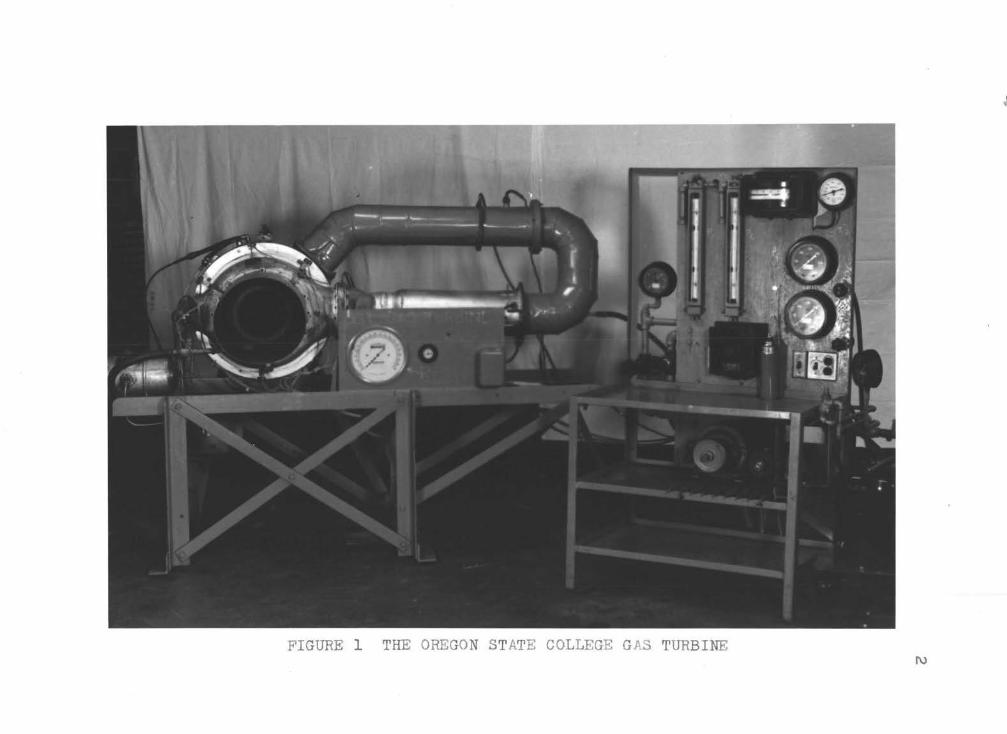
2
3
scattered and did not indicate a trend through wh ich a curve
could be drawn
Theoretically in order to do work by passing a
gas through a turbine wheel there must be a temperature drop
and a pressure drop The required pressure drop across thebull
turbine is quite easily measured but to date the measured
temperature or the exhaust gases has always been greater
than the temperature of the inlet gases This is another
indication that the temperatures have not been accurately
measured
In the second unit the t hermocouples measuring the
turbine inlet temperature were placed in two locations The
first location was in a hollow stainless steel staybolt
while the second location was about 3 or 4 inches ahead or the hollow staybolt in a removable elliptical steel section
These two locations are shown diagrammatically in Figure 2a
As may be seen from Figure 2b the elliptical section was
made in such a manner that four t hermocouples could be
placed in the section at once
The exhaust thermocouples measuring the turbine
exhaust temperatures were placed in three positions 120
degrees apart around the exhaust ring These three thermoshy
couples were approximately 3 inches from the turbine wheel
When an attempt was made to explain the reasons
for t h e peculiar temperatures measured it was thought that
CombuatiOD Chlmbtr
( a ) (b)
FIGUFE 2 (a) DI A middot~ Jn~T IC AL Sr~middot~TC H OF PREVIOUS THERMOC OUPLE IUSl ALLAIlOJ S (b) PLAN VI~W OF ELLI PTICAL SECTION
5
there were several factors causing the inconsistency Since
the thermocouples placed in the elliptical section were
actually at the throat of tha exhaust of the combustion
chamber the velocity at that section was quite high--in the
order of 200 to 500 feet per second Therefore the portion
of the gas that slows up as it approaches the thermocouple
imparts a portion of its kinetic energy to the thermocouple
increasing its temperature above that of the static gas
temperature Also the location of these thermocouples in
the elliptical section made it possible for the thermoshy
couples riot only to see the flame but also to bullsee the
cold walls of the section This gas radiation to the
thermocouple tends to increase the thermocouple 1 s temperashy
ture while the thermocouples radiation to the cold walls
tends to reduce its temperature For a time it was thought
that the radiation loss caused by the cold walls would tend
to offset the gain in temperature caused by the gas radiashy
tion and by the kinetic energy of the gas Since the temshy
perature measurements were inconsistent however this idea
was discarded Various stainless steel shields were tried
several times but they did not correct the situation
The thermocouple placed in the hol~ow staybolt
actually had a stainless steel shield around it so some of
the radiation loss and gain should have been decreased but
the thermocouple junction measured a temperature several
6
hundred degrees lower t h an t hat measured by the thermoshy
couples in the elliptical section This difference was beshy
lieved to be caused by the radiation gain by the thernwbull
couples in the elliptical section due to r adiation from the
flame and by the conduction loss along the hollow stainless
steel staybolt
The exhaust thermocouples have three factors
entering into possible causes for errors in their readings
These factors are the kinetic energy change due to slowing
up of the gases as they pass the junction and the heat
radiated to and from the thermocouple
Since t his gas turbine was built f or a dual
purpose (demonstration and testing) it is necessary to
measure with a certain degree of accuracy t h e temperature at
various critical points in order to conduct a worthwhile
test As has been previously stated up until this time
these temperatures h ave not been measured accurately It is
the purpose of this thesis therefore to select and test
several pyrometers which can be used for high-temperature
gas stream measurement If the tests should prove that a
pyrometer can measure the required temperatures accurately
it will be used as a permanent temperature-measuring instrushy
ment for the turbine
7
SELECTION OF THE PYROMETER
A pyrometer must have certain requirements for
each individual installation in order to be able to measure
the temperature of the gas stream accurately In this inshy
stallation it is desired to measure the static temperature
rather than the total temperature as is commonly measured in
high-temperature gas streams These two terms are defined
as follows
1 Stmiddotatie temperature is that temperature which
would be indicated on a recording instrument
if the temperature- measuring device were
traveling with zero relative velocity with
the gas stream
2 Total temnerature is that temperature which
would be indicated on a recording instrument
if the t emper-ature-measuring device were
stationary and the measuring device absorbed
all of the energy given up by the gases as the
gas velomiddoteity approached zero
The statie temperature is the temperature desired
since it is t h is temperature along with the static pressure
that completely defines the thermodynamic state of the gas
(3 p bull219) bull Therefore the pyrometer selected must measure
thei static temperature or lt must be possible to corremiddotet
the measur-ed temperature to give the static temperature In
8
this installation it is expected that the gas streams
temperature varies across the turbine casing so the pyromshy
eter either must measure the average temperature or it must
be adaptable for use in a temperature traverse It is known
also that at any one point there is a rapid temperature
fluctuation therefore the response rate of the pyrometer
need not be fast in order to obtain the desired average
temperature
The pyrometer also must reduce the radiation --shy
conduction and convection losses to a minimum Other reshy
quirements that should be met are simplicity low cost
reliability and durability
There are many different pyrometers for measuring
temperatures but only a few of these methods will meet the
above requirements Some of the most used methods are as
follows
1 Thermocouples both bare and shielded
2 Sonic pyrometer
3middot Pneumatic pyrometer
4 Resistance thermoelement
A brief discussion of each pyrometer is given below
Thermocouples
Pyrometers employing thermocouples have become
quite popular over a period of years due to their simplicity
accuracy low cost and ease of production However they
9
still are subject to errors such as conduction los~ along
the wires and along the thermocouple well radiation loss
rrom the thermocouple junction to the cold walls radiation
gain rrom the hot gases to the junction and impact error
due to the high-velocity gases striking the thermocouple
Also they have an inherent property of only being able to
measure the temperature at one small point In order to
obtain an average temperature therefore it would be necesshy
sary to use many thermocouples and average the readings
Numerous investigators lt4 pp l53-160) (11 pp
421-425) and (16 p334) have attempted to correct the readshy
ings or a thermocouple by incorporating various forms of
shielding to reduce the errors due to radiation It has
been reported by A I Dahl and E F Flock that if a silver
shield were pressed on a thermocouple the errors due to
radiation would be negligible lt4~ plS6) This same silverbull
shielded thermocouple gives excellent performance because of
its ruggedness rapid response and ease of construction
Another type of radiation shielding consists of
two tubes concentrically placed with the thermocouple in the
center (16 p bull334) Another thermocouple is placed between
the two concentric tubes and a coil of wire is wrapped
around the center tube This cot l of wire is connected in
series with a voltage source and a current-limiting device
During operation the current is adjusted in the coil until
10
the two thermocouples indicate the same temperature At
this point the center shield is at the same temperature as
the main thermocouple so there can be no heat loss due to
radiation from the main thermocouple to the first shield~ A
sketch of this thermocouple is shown in Figure 3bull This
thermocouple gives very good results but due to its conshy
struction and elaborate control necessary to maintain the
center shield at the required temperature it is only suitshy
able for installations in which the temperature is relativeshy
ly constant
Another shield used by Wbull J King (11 Pbull424gt uses
a thermocouple with quadruple shields spaced 116 inches
apart~ These shields are 2-12 inches long and made of 18-8
stainless steel The accuracy of this thermocouple is not
quite as good as that of the other two and due to its large
outside diameter 1-18 inches it is limited to use in
large-size ducts~
Shielding of various forms and sizes also has been
used in trying to obtain the maximum amount of heat transshy
fer from the change in kinetic energy due to stopping the
gases by the thermocouple W J King reports on a
diffuser-type shield probe (11 P~424l used to avoid velocshy
ity er~ors which has been quite successfUl for velocities
from 150 to 600 feet per second and at room temperatures
11
Voltage Source
Ma Th
1Ull1voltmetera
Mar( AliI I ~ I I L----1s J
in f-Auxilia7 ermocouElbullshy Thermooou2lbull
~
I 1 Cka I n
L Heater
FIGURE 3 DOUBLE-SHIBLDED THRMOCOUPLB CENTER SHIELD BLECTRICALLY HEATED middot
12
This probe however does not have adequate shielding for
radiation so it is unfit for high-temperature usage
Another group of investigators (1 pp338-J4l) has
reported on numerous designs of shielding to be used to reshy
cover the maximum runount of kinetic energy in the gas The
shields developed recovered nearly all of the total availshy
able energy caused by the change in velocity in the form of
heat and so they measure the total temperature quite accushy
rately In this case however the static temperature is
the one desired so they would not be suitable for this use
unless the velocity at the location of the thermocouple were
known
Sonic Pyrometer
The sonic pyrometer (17 pp851-858) was developed
by E P Walsh Sidney Allen and J R Hamm for the express
purpose of measuring the total temperature of a highshy
temperature low-density gas stream This type of pyrometer
incorporates three essential parts the thermocouple the
flow nozzle and the encasing tube but other parts may be
added depending upon the accuracy desired For instance
in order to decrease radiation a second tube is placed
around the first and gas is drawn through the annular space
raising the inner tube temperature to that of the gas middot In
order to decrease conduction loss the high-velocity gas may
be allowed to pass over the therrnocouple wfres for a short
13
distance A sketch of this type of pyrometer is shown in
Figure 4- The principle upon which this pyrometer operates
is that if a gas is allowed to pass through a flow nozzle at
such a rate that its velocity approaches the velocity of
sound and that if a thermocouple is placed within the flow
of this gas stream then a maximum amount of heat will be
transferred to the thermocouple giving the maximum temperashy
ture obtainable This point of operation may be found by
varying the gas flow through the nozzle When the flow
reaches such a point that the temperature of the thermoshy
couple does not increase then sonic velocity is obtained
The true static temperature then may be found by applying
the following equation
(1)
where ls Static temperature R
Tj =Junction temperature R
V =Velocity ftsec
g =Acceleration of gravity ftsec2
J =Heat equivalent of work Btuft lb
cp bull Specific heat at constant pressure Btulb R
102 bull Conversion factor for obtaining themiddottotal temperature of the gas stream (17 p852)
Gas Flop
To Suction
o K1111Yoltmeter Plow
l
FIGURE 4 SONI C PYROMETER
15
fhis type of pyroraeter then gives a relatively
simple method for measuring the static gas temperature of
not only constant- temperature gas streams but also of
rapidlychanging- temperature gas streams due to lts rapid
response rate
Certain eharaeterlstic features of this instrushy
ment however make it less desirable for this application
For instance with -a suction pyrometer correeted for r-adiashy
tion two suction pumps must be used and their coat plus the
cost of construction or the pyrometer will give a high total
cost Also in order to calibrate the pyrometer in the
easiest possible manner it take-s quite an elaborate and
costly selection of instruments Walshbull Allanbull and Hamm
used a gravimeirie chemical analysis of the gas stream in
order to obtain the true temperature This grtavimetrtc
technique as described by L1oyd (12 pp 335 34l) ha-s proved
to be quite accurate
This pyrometer is only capable of obtaining the
temperature at ane point in the gas stream ln order to
obtain a true average temperature either a time-consuming
temperature traverse would have to be talten or several
sonic pyrometers would have to be installed at various pomiddotaishy
tions which would further increase the cost bull
Still another disadvantage is that this pyrometer
requires a definite amount of gas to be drawn off through
16
the pyrometer In this ease the amount of gas flow in the
unit is critical and all gas flow should be used in driving
the turbine bull
Pneumatic Pyrometer
The pneumatic pyrometer as developed by the Fairshy
child Camera and Instrument Company (15 pp30-34) is a
relatively simple device It consists of a tube containing
two small orifices with a heat exchanger located between
these orifices A sketch of this instrument is shown in
Figure 5a In order to measure the temperature of the gas
stream a sample of gas is drawn into the tube and passed
through the first orifice~ The gas is then cooled by the
heat exchanger and is passed through the second orifice
after which it is discharged into the atmosphere It is
then only necessary to measure the pressure drop across both
orifices and the temperature at the second orifice These
values are then used with the equation
(2
where - Static temperature before the first orifice RTsl shy- Static temperature before the second orifice RTs2 shy- Static pressure before the first orifice psiaPsl shy
Static pressure before the second orifice psiaPs2 = Static pressure after the second orifice psi aPs3 =
17
bull
Heat Exchanger
1 CoJQbu1tion Oyta
FIGURE Sa PAIRCHILD PNEUMATIC PYROMETER
Gae now Probe
o Draft Gagel
~ To Suction
FIGURE 5b PNEUMATIC PYROMETER
18
K =Constant cont aining the orifice coefficients and areas
when the difference (Psl- Ps2) is small
With t h is t yp e of instrument it is possible to
c alculate the temperature of the gas ~t~eam very closely
This is due to t h e fact that t h e only he at loss will be by
radiation from the gas to the walls wh ich is a very small
amount The response of this instrument is almost instanshy
taneous since the density of the gas stream changes with
temperature and any change in density must immediately afshy
feet the pressure drop across the first orifice
Like the sonic pyrometer t h is instrument has the
inherent property of only being able to measure the temperashy
ture at one point and while doing so a sample of gas must
be by- passed through the instrument both of which are conshy
sidered undesirable in t h is case
Another type of pneumatic pyrometer (Figure 5b) is
that developed by J A Clark and W Ht Rohsenow ( 3 pp 219shy
227 ) bull In t his pyrometer a portion of gas is pulled through
a tube by a suction pump in a way s imilar to that used with
the sonic pyrometer Various values of pressure are measured
at the inlet to the tube and the flow is measured by an
orifice after the gas has passed t hrough a heat exchanger
These values are t hen used in Equation 3 to find the static
temperature at the inlet to the probe
19
3)
where Tsl bull Static temperature R
Conversion faetor 322 lbmsee2 lbf
~ Gas constant ft lbflbm R
Static pressure lbfft2
2bull Mass flow lbmsec rt
bull Ratio of specific heats dimensionless
Total pressure lbfrt2
It may be noticed in Equation 3 that Tsl depends
upon the gas composition However R1 (the gas constant)
can be assumed to be the same as that for air since the
amount of fuel added is very small compared with the amount
of air but the value of k changes materially with varying
gas concentrations J A Clark and W H Rohsenow have
shown that if k is assumed to be 1250 the calculated temshy
peratures by Equation 2 will not vary more than 2 per cent
over that calculated by using the true value of k as deshy
termined from the gas composition
This pyrometer is quite easily calibrated Since
it may be done at room temperature all effects of heat exshy
change by conduction convection and radiation can be
eliminated The calibration is performed to obtain the
required flow necessary for accurate results
20
One inherent pro perty of this method that makes it
advantageous for this use over that of the thermocouple is
that as the temperature and velocity of the gas are inshy
creased the accuracy of the results also increases
The pyrometer can be constructed to give a simple~
cheap durable instrument If it is made of stainless steel
and is water cooled it may be used at extreme temperatures
without being subject to effects of corrosion
As with the shielded thermocouples~ the sonic
pyrometer_ and the Fairchild pyrometer the temperature
found by this method is measured at one point In order to
obtain an average temperature either several pyrometers or
a temperature traverse would be necessary
Resistance lhermoelement
Since 1871 when Siemens suggested using the
property of changing r~sistance with temperature of various
materials for measuring temperature t he resistance thermoshy
element has become quite popular
The two materials used at present for most ternbull
perature measurements by resistance thermoelements are pure
nickel and pure platinumbull Nickel is used for only lowshy
temperature measurements up to 450 F This limitation on
its useful temperature range is caused by the change in the
temperature- resistance curve as the transition point of
nickel is approached and by the danger of oxidation Bare
21
platinum on the other hand can be used up to temperatures
of 1800 F without difficulty if it is in the presence of an
oxidizing atmosphere Usually however the platinum eleshy
ment is placed within a shield This shield performs two
functions (1) that of a rigid support and protection of the
element and (2) t hat of radiation correction
Errors in the readings of resist ance thermoshy
elements are subject to the same factors that enter into
temperature measurement by thermocouples Consequently it
is necessary to apply corrections to t he readings of a reshy
sistance thermoelement similar to t ho se of the thermocouple
readings A resistance thermoelement however has another
characteristic which must be considered and that is the
current-carrying capacity of the wire The effects of the
current on heating and thus changing the resistance must be
watched closely or incorrect results will be obtained
Temperature lag of a shielded resistance thermoshy
element is much greater than that of any of the other types
of instruments mentioned previously but it does not measure
the tempe r ature at a point in a gas stream as the other
types of instruments do It measures the average temperashy
ture of the g as stream If this resistance thermoelement is
connected to a wheatstone bridge or a similar type of appashy
ratus the t hermoelement is very sensitive to temperature
changes
bull 22
Now after examining the various pyrometers the
pyrometer which meets the requirements can be selected Two
pyrometers were selected to be subjected to tests for their
suitability for this installation
The silver-shielded Chrome1-Alumel thermocouple
was selected because of its accuracy reduction in radiation
losses availability low cost and simplicity It i s true
that it does not measure the average temperature but with
several thermocouples the average temperature may be obshy
tained
The resistance thermoelement was also selected
because 9f its inherent property of measurmiddoting the average
temperature It was realized that the cost of a platinum
resistance thermoelement was prohibitive and ~hat nickel was
out of the question but it was felt that if another material
could be found this method would be excellent for measuring
the temperatures desired It was also realized that the
errors obtained in resistance thermoelements are the same as
those middotfor the silver-shielded thermocouple except for radiashy
tion but correction for this error can be made
middot It was decided that two trial thermoelements would
be made--one from Inconel wire and the other from Chromax
wire--to determine their suitability~
23
THEORY OF TEMPER ATURE MEASUREMENT BY THERMOCOUPIE S AND RESISTANCE THERMOELEMENTS
The first thermocouple used to measure temperature
was devised by Seebeck in 1821 This tempe r ature-measuring
device was a direct result of his discovery that when the
junction of two dissimilar metals is heated~ an electroshy
motive force is generated (18 p33)bull This potential was
later found to be the algebra c sum of three separate
electromotive forces
These three electromotive forces are due to what
is known as the Peltier effect the Thompson effect and the
Becquerel effect (2 p l09) The potential generated by the
Peltier effect is due to heating a junction of two dissimishy
lar metals whereas the Thompson effect generates an electroshy
motive force when there is a temperature difference along a
homogeneous wire The Becquerel effect generates an electroshy
motive force when there is a physical or chemical inhomogeshy
neity in a single wire This effect is usually negligible
in good thermocouple wirebull
The algebraic sum of these three electromotive
forces varies with the temperature difference between the two
junctions of a thermocouple circuit A simple circuit is
shown in Figure 6
If Junction 1 is maintained at a definite temperashy
ture while Junction 2 is heated then the electromotive
~___--- ____ _
-~ ~Wire A middot~
1 2
Millivoltmeter
FIGURE 6 SIMPLE THERMOCO U LE CIRCU IT
Whe a tstone Bridge
Unknown Re sist a nce
FI GUPE 7 WHEATSTONE 2PID~ Ci ~ _ fJl
25
roree indicated on the millivoltmeter will be the algebraic
sum of the two electromotive forces generated at each juneshy
tion and will be an indication of the actual temperature at
Junction 2 The temperature at 1hich Junction 1 is kept is
usually 32 F and is maintained by i mmersing it in chipped
ice and water Junction 1 is usually called the cold
junction while Junction 2 is called the hot junction
Curves and tables of millivolts versus temperature
can be obtained from any of the reliable thermocouple manushy
facturers A typical table is shown in Appendix B
The most common combinations of materials used to
produce good temperatue versus electromotive force curves
are given in Table I with their operating temperature range
Table I
Combination of Materials for Thermocoupl Use
Material TemEerature Range F
Copper-Constantan Iron-Constantan
32 32
- uo00
Chromel-Alumel 32 - 2200 Platinum-Platinum Rhodium 1000 - 2650 Chromel-Constantan 32 - 1400
The ability of metals to change their electrical
resistance with temperature as a means to measure temperashy
ture was first suggested by Siemens in 1871 The change in
resistance of metals with temperature is due mostly to the
26
activity of the molecules within the metal as the temperashy
ture varies
In order to measure this temperature it is usualshy
ly necessary to use a wheatstone bridge circuitbull With this
circuit the resistance can be measured at any temperature
Then by use of a temperature versus resistanc e curve it is
possible to obtain the true temperature This t ype of
instrument will give good results due to its inherent
accuracy and sensitivity A typical wheatstone bridge
circuit is shown in Figure 7
Metals that are usually used in making resistance
thermoelements and their operating temperature ranges are
listed in Table II
Table II
Suitable Metals for Resistance Thermoelements
Metal Temperature Range F
Pure Nickel -328 - 4-82
Pure Platinum -310 - 2000
One advantage that the resistance temperatureshy
measuring circuit has over the thermocouple circuit is the
elimination of a cold junction This eliminates the chance
for error in the measured temperature because of fluctuashy
tions in the cold-junction temperature
27
With the exception of the error due to the cold
junction the errors obtained in me asuring the temperature
by a thermocouple are the same as those for a resistance
thermoelement The fol lowing discussion therefore will be
applied only to the thermocouple It must be understood
however t hat the s ame discussion and mathematical formulas
may be used with the resistance t hermoelement
Four major factors tend to produce a difference
between the measured thermocouple temperature and the actual
temperature of a gas stream These four f actors are
1 Heat loss due to conduction along the thermoshycouple wires and well
2 Heat loss due to r adiation from the thermocouple junction to the cold walls
3 Heat gain due to radiation from t he gas to t he thermocouple
4 Heat gain due to a change in kinetic energy as the gas stream approaches the thermocouple
In this discussion each factor will be discussed individualshy
ly and then collectively
~~~ to Conduction
Since the main purpose of the thermocouple is to
measure the temperature of the gas stream accurately it is
necessary to determine whether or not the conduction loss
can be made negligible Jakob and Hawkins (8 p203) have
treated this subject very well They have found that the
error obtained in the temperature indicated by the
28
thermocouple and that of the true temperature neglecting
radiation loss may be found from the equationbull
ts - tw ts- tj ----== lt4gt
cosh LWi
where t Static temperature F s -shytj - Junction temperature F-
Wall temperature F t = L Depth of immersion rt= h Heat tra~sfer coefficient by convection=
Btuft- hr F
c Circumference of well material ft= kt ~ Thermal con~uctivity of well material
Btu ftft hr F
A =Cross-sectional area of well material rt2
when the thermocouple wires are small
From Equation 4 it may be seenbull that t here are five
values that can be used to reduce the error caused middotby conshy
duction These factors are as follows
1 Insulate the wall to bring tw t 8
2 Make L as long as possible
3 Reduce the cross-sectional area to a minimum
4 Use a well material with a low t hermal conductivity
5 Make the he at transfer coefficient as large as posshysible by increasing t he velocity of t he gases
29
In view of these five factors it was decided that
the depth or immersion is the easiest to control With this
in mind a family of curves was plotted by using Equation 4 with the depth of immersion as the abscissa and the ratio of
t he temperatures as the ordinate This family of curves is
s hown in Figure 8
From these curves it can be seen that the error in
the thermocouple reading will be less than 1 per cent if the
thermocouple is i mmersed into the gas stream at least o6 inches It may be concluded therefore that if the thermoshy
couple is inunersed into the gas stream a distance of 06
inches or more the error produced will be negligible and
the thermocouple will g ive the true temperature
~ Loss ~ Radiation
Theoretically the heat loss due to radiation from
a hot body to a cold body is proportional to the difference
of the fourth powers of their respective absolute temperashy
tures If t his heat loss is set equal to the heat gain by
convection while assuming the conduction and velocity
effects a s being negligible there results an equation from
which the temperature of the gas can be calculated Th is
equation is as follows
(5)
rt bullmiddot +tshy
hmiddot
tt tt_ f+ 1_ _ middot 1_ bull middot
t ti rrrmiddot middot111 middot middot middot -shy
middot - -- - --middot _ = c_ - middot
L-t _ -_~ t_r t- middot~r
tf-7
I ~~ middot ~crt~~ rtn 11
i
$~
31
where At bull Area of the t hermocouple ft~
h =Heat transfer coefficient by convection Btutt2 hr F
ts Static temperature F
tj - Junction temperature F
tr = Stefan-Bolt~manp s radiation constant Btuhr ft RLlshy
6 bull Emissivity of the junction dimensionless
Tj =Junction temperature R
Tw bull Wall temperature R
It is often quite difficult~ however to measure the effecshy
tive wall temperature and it is much more difficult to deshy
termine the actual emissivity of the junction (5 pl52)
Therefore the method most commonly used to correct for
radiation is by some physical means This may be accomshy
plished either by shielding the thermocouple from the surshy
rounding cold walls by coaxial shields or by increasing the
wall temperature Since it is often quite difficult to
increase the wall temperature many investigators have deshy
vised various forms of shielding for the thermocouple
These shields tend to reduce the ability of the thermocouple
to follow fluctuating temperatures however and are quite
difficult to install
Another common method for reducing the radiation
loss is to use junctions of low emissivity As can be seen
from Equation 5 the heat loss by radiation is directly
32
proportional to the emissivity of the junction If this
emissivity is reduced the heat loss will be decreased and
the junction temperature will approach the true gas temperashy
ture A I Dahl and E F Flock have developed a junction
covered with silver in which the emissivity is reduced to
0 05 lt4 p l54) This reduced the heat loss to 1 16 of that
for a bare oxidized Ghromel - Alumel junction A comparison
or Chromel-Alumel thermocouples with different radiation
shields is given in Table III
Table III
Effectiveness of Radiation Shields (5 p 155) True Gas Temperature 1500 F Wall Temperature 1200 F
Shields
1 Coaxial 3 Coaxial Pressed Pressed None Tube Tubes Silver Platinum _ -
Indicated Ternperashy
ture F 14-32 1480 1494 Radiation Correcshytion P 68 20 lO 6 22
From Table III and from the curves shown in
Figure 9 it may be seen that the error in the indicated
temperature is less than 1 per cent Therefore in most
eases the indicated temperature may be assumed to be tha t of
the true static gas temperature
FIGURE 9
EFFECTS OF RADIATION ON THE TEMPERATURE MEASURED BY A SILVER-SHIELDED ~HERMOCOUPLE
Aa Computed from Equation 5a A
34
~ S Ez Radiation
The heat gain by the thermocouple due to radiation
from the gas stream is of relatively small value This is
especially true in g as streams in which the air-fuel ratio
is quite high In t h is installation t he air-fuel r atios are
in the order of 60 to 85 pounds of air per pound of fuel
This gives a combustion gas composition assuming co mplete
combustion as is shown in Table IV
Table IV
Variation of Combust i on Gas Composition
Range of Composition Combustion Gases by Volume
Carbon Dioxide 35 - 25 Water Vapor Oxygen Nitrogen
29 - 20 158- 175 778 - 780
It can be seen from Table IV that the amounts of
nonradiating gases oxygen and nitrogen are many times that
of t he radiating g ases c arbon dioxide and water vapor
(13 p64) therefore the emissivity of the total g as
stream would be extremely small and the heat gain by radiashy
tion from the gases can be assumed to be negligible
If t he thermocouples are placed in such a position
that they can see t h e fl ame then there may be a considershy
able heat gain due to radia tion since during combustion
35
there are higher concentrations of radiating gases and lower
concentrations of nonradiating gases
Heat ~~ to Kinetic Energy Change
If a thermocouple is immersed in a rapidly-moving
gas stream it will tend to slow up a portion of this gas
stream As a result of this change in velocity the temshy
perature of the thermoco~ple will increase This increase
is due to three effects (1) the transfer of kinetic energy
oC the random molecular motion by collision (2) the transshy
fer of kinetic energy by direct impact and (3) the transfer
of heat generated by friction due to the flow of gases
around the junction (5 pl57) If the thermocouple were
able to absorb all of the kinetic energy~ ~he temperature
indicated by the thermocouple would be the total temperature
This may be expressed mathematically assuming that the proshy
cess is adiabatic in the following equation
v2Tt middot= Ts f (6)
2gJep
where - Total temperature RTt -Ts -- Static temperature R
V bull Velocity ftsec
g Acceleration of gravity ftsec2
J =Heat equivalent of work Btuft lb
cp =Specific heat at constant pressure Btulb R
It is practically impossible however for the
thermocouple to absorb all of the energy available This is
due to the ~act that the process is not entirely adiabatic
and that as the temperature of the thermocouple approaches
the total temperature it tends to lose heat to the gas
Therefore the thermocouple will reach an equilibrium temshy
perature somewhere between the total temperature and the
static temperature This point has been found to be apshy
proximately 85 per cent of the theoretical increa se for a
bare thermocouple In other words the junction temperature
expressed mathematically is
(7)
where Tj - Junction temperature R-ls - Static temperature R
v Velocity rtsec
g bull Acceleration of gravity ftsec2
J -- Heat equivalent of work Bturt lb
c =Specific heat at constant pressure~ Btulb R p
The factor 085 is commonly referred to as the recovery
ractor o for the thermocouple bull
A curve for velocity versus temperature difference
is shown in Figure 10 for recovery factors of 100 and 085 It can be seen from this curve that for a recovery factor of
100 and a velocity of below 300 feet per second the error
m~um-T ~~- FIGURE 10 l I
~ 16 ~ EIltFECTS OF VELOCITY ON THE TEMPERATURE ~ middot MEASURED BY A THERMOCOUPLE 1-Hti 11 -t~ _j t ~r-r ITt -t- As Calculated from Equati ons 6a and 7a 77 ~~ ~ Appendix A ~-t
-
Lltt lfi 37
J j
1
tj
1 l
I l
- tJ~ ~ 500 [ gn tctfl q ~ rr~
38
in the true static temperature is less than l per cent
Therefore for this velocity and below the measured temshy
perature may be assumed to be that of the static temperature
Above this velocity the error increases rapidly for a small
change in velocity
In the above discussion each effect was considered
separately Now they will be considered together If a
heat balance is written for a thermocouple in equilibrium
it will be noticed that the heat transferred by convection
from the gas stream to the thermocouple plus the heat transshy
ferred by radiation from the gas stream to the thermocouple
plus t he heat transferred by the change in kinetic energy of
the gas stream must equal the heat lost by radiation from
the thermocouple to the cold walls plus the heat lost by
conduction along the thermocouple wires and well If the
heat loss due to conduction and the heat gain due to gas
radiation are negligible then the effect of the kinetic
energy change tends to offset the effect of radiation on the
thermocouple junction temperature This is only true howshy
ever for gas velocities below 400 feet per second and for a
silver-shielded thermocouple with a recovery factor of 085
or less The temperature indicated on t he measuring instrushy
ment below t his velocity may then be assumed to be essentialshy
ly the true static temperature
39
CONSTRUCTION AND PLACEflampN~ OF PYROMETERS AND EQUIPimNT
SilverShielded Thermocouple
Since the previous thermocouple installation alshy
lowed the thermocouples to ttsee the flame and since they
were placed in the section of highest velocity it was debull
cided that it would be better to place the new thermocouples
in an area of lower velocity end in a position where they
could not see-If the flame The three thermocouples at the
turb-ine inlet therefore were placed 120 degrees apart
around the turbine casing with the silver shield of the
thermocouple about 12 inch upstream from the nozzle ring
and directly opposite the nozzle inlets The three thermoshy
couples at the turbine ex~aust were placed directly opposite
the thermocouples at the turbine inlet and about 1-12
inches downstream from the turbine wheel blades
The thermocouples were madmiddote of No 20 Chromelshy
Alumel thermocouple lead wire A section of the wire was
cut off to the desired length depending upon whether the
thermocouple was to be used in the inlet casing or in the
exhaust casing - The lengths required are 8 inches for the
turbine inlet temperature and 5 inches f or the turbine exshy
haust temperature
The thermocouple bead was formed by twisting the
two wires together for a distance of 12 inch The ttlisted
portion was then heated in a neutral acetylene flame until
both wires glowed bright red The wires were then dipped
into bronzing flux until a good coating was formed The
flux- coated ends were immediately placed into the flame
until the bead formed After the wires cooled the flux
was broken off and the wires and bead were cleaned with
a wire brush
The silver shield was made from a tube 1 8 inch in
diameter and with a wall thickness of 0 020 inches This
silver tube was cut into 1 2- inch lengths Eaeh length was
slipped over a thermocouple bead until the bead was halfWay
into the shield The shield was then pressed tightly on the
thermocouple wires and bead The tighter the silver is
pressed on the bead the better the heat transfer is between
them After the shields were pressed on the beads the
ceramic insulators were slipped over the thermocouple wires
The terminal strip and individual connectors were
all made of fiberboard The terminal strip contains enough
terminals for twelve thermocouples and was used to join the
Chromel- Alumel lead wires to the copper wires of the switch
Each connector contains two brass cylinders into which the
thermocouple wires and the lead wires were placed These
wires were then clamped into place by set screws
Since the thermocouples at the turbine inlet were
to be placed in the turbine casing it was necessary to
construct a thermocouple support These supports were made
of 7 16- inch hexagonal head mach ine bolts (the heads of
which were ground to fit t he ca sing) These machine bolts
were t h en drilled with a 732- inch drill to provide the
necessary opening to f acilitate t he installation and removal
of the thermocouple Due to the curvature of t h e casing ~ it
was necessary to grind a s pa cer to fit closely to the outshy
side of the ca sing in order to prevent gas leakage around
t he supporting bolt A hexagonal he ad machine nut was used
to hold the assembly in place A bushing drilled out to
0 15 inches for the ceramic insulator was used to hold the
thermocouple in its support An exploded view of the
t hermocouple and its support is shown in Figuremiddot 11 and a
t ypical assembly drawing is shown in Figure 12
The supports for t he exhaust t h ermocouples were
made of 14- inch brass machine screws These screws were
held in place by a l4- inch hexagonal head machi ne nut A
0 152- inch hole was drilled longitudinally through t he bolt
for the ceramic insulators on the thermocouple
Resistance Thermoelement
The resistance thermoelement was to be made by
coiling the resistance wire in the form of a loop approxibull
mately 12 inches in diamter and passing it in front of the
entire circumference of the nozzle ring It was believmiddoted
that by doing t h is t he actual average temperature of the
FIGURE 11 EXPLODED VIEW OF THERMOCOUPLE AND ITS SUPPORT 1 Support bolt 2 Sp acer 3 Connector and connector bracket4 Spacer 5 Hexagonal head nut 6 Thermocouple bushing 7 S ilver-shielded thermocouple
3
Thernocou~ le S ~1pp o - t Bo lt
Nozzle Ring -~
Thermoc ounle Wires
Bushing
~-+~ Porcelain Insulator
F JEE 12 TYPICAL ASSEMBLY OF
~ ~ERMOCOU PLE AND SUPPORT
gases passing through the nozzles could be obtained This
is due tc the fact that the variation of the mass flow
across the entrance to the nozzle section is at a minimum
In other words the velocity of the gases entering the
nozzle will not vary substantially from the bottom of the
nozzle to the top of the nozzle- The materials from whieh
these thermoelements were to be made were No 20 Chr-omax
wire arid No 22 Ineonel wire The coils were to be supported
by insulators fastened to bolts extending down through the
thermocouple supports The exhaust thermoelement was to be
constructed and supported in a similar manner
The support for the thermoelement to be used in
the preliminary tests to determine the suitability of the
wire to t emperature measurement was made from a heater eleshy
ment core similar to that used in the ordinary household
electric heater Three feet of VIire was wrapped -on this
porcelain core and two copper leads of No 10 wire were
fastened to each end of the thennoelement
Pressure Probe Section
The pressure probe seetion was made of l - inch steel
plate with an 8 x 4- 5 16- inch elliptical opening A photoshy
graph of this section is shown in Figure 13 The pressure
probes were made from No 321 stainless steel tubing
18- inch in diameter with a wall thickness of 0 020 inches~
45
46
There were three total and two static pressure probes a-cross
the horizontal and vertical dimensions Each pzrobe was
located in the center of an area equal to onebullthird of the
total area of the opening The entire unit is located in
the transition section between the combustion chamber and
the turbin~ casing
Ihe purpose oi this pressure probe section was
to determine the velocity of the gases as they leave the
combustion chamber Sinee this section has the smallest
cross-sectional area and the highest weight now the veshy
locity at this point will be higher than at any point in
the turbine casing This is due to the fact that as soon
as the ga ses enter the combustion chamber a portion of the
gas leaves the chamber through the nozzles This gives a
varying weight flow around the entire turbine casing
Therefore if the velocity at the elliptical section is not
appreciable the yelocity at any other point in the easing
Vlll be lower and it will aTect the temperature indicated
by the thermocouple very little
I
47
TESTS
Apparatus
The apparatus other than the g as turbine used in
t he thermocouple tests can be divided into two groups
(1) t h e e quipment for temperature measurements and (2) the
equipment for other measurements The equipment contained
in the first group is as follows
l The silver-shielded t hermocouple
2 Cold-junction thermocouple
3 Twelve-point switch
4 Englehard millivoltmeter
The other equipment may be listed according to the values
measured as follows
1 Air flow - Ellison draft gage c ap acity 6 in water
2 Fuel rate - Toledo Seales and stop watch
Velocity pressure - Mariam water manometer capacity 60 in water
4shy Static pressure - Mariam mercury manometer capacity 14 in mercury
The electrical circuit for the thermocouple is
shown in Figure 14 This circuit contains t he t hermocouples
terminal strip 12-point switch and the millivoltmeter It
may be noticed from Figure 14 t h at the Chromel-Alumel lead
wires run only as far as t he terminal strip From t hat
point on t he wires are made of copper At first glance it
may seem that this would cause an error in t he readings but
48
Copper Wire--~------~
ChroMl Wire Alumel Wire
Cold Junction
FIGURE 14 ELECTRICAL CIRCUIT FOR THERMOCOUPLES
Rebull1bulltanee lbtlW)tliMDt
Wheatstone Bridge Potentiometer
FIGURE 15 ELECTRICAL CIRCUIT FOR RESI ST ANCE THERMOELEMENT
49
if the cold-junction Vires are connected to the copper wires
at the terminal strlp then all copper-Chromel and coppershy
Alumel junctions will be at the same temperature and no
error will occur 6 p 85)
The apparatus for the tests on the resistance
thermoelement can also be divided into two groups (1) the
equipment used in the preliminary tests and (2) the equipshy
ment which was to be used in the final tests The equipment
in Group 1 is listed as follows
1 The resistance thermoelement
2 Leeds and Northrup wheatstone bridge
3 arshall-Hall tubular furnace
4 Wbeelco controller and its thermocouple
5 Comparison Chromel-Alumel thermocouple
6 Leeds and Northrup potentiometer
The electrical connections for t h is equipment are shown in
Figure 15 The equipment contained in Group 2 is the same
as the equipment used in the thermocouple tests except that
in place of -the temperature- measuring e quipment the followshy
ing equipment was to be used
1 Resistance thermoelement
2 Leeds and Northrup wheatstone bridge
Procedure
The procedure used in conducting the test on the
thermocouples and the procedure which was to be used for th~
final test on the resistance thermoelement were similar
The original method of conducting the tests consisted of
bringing the turbine up to a definite speed and jockeying
the fuel control valve to maintain this speed~ After the
designated speed had been reached a series of readings of
all values were taken The fuel r ate was measured in seconds
per half-pound and was measured twice during each run
The values obtained from this test were quite
erratic _ Since it was necessary to constantly jockey the
fuel control valve t o maintain a derinite speed the conbull
ditions could never reach a static state Consequently
it was decided to revise the procedure by adjusting the
throttle once and letting the turbine reach its own speed
After this had been stabilized a series of readings were
taken as before The results obtained by this method were
more consistent_ so this procedure for controlling the turshy
bine speed was used
throughout the test A series of 8 to
10 readings each at a different turbine speed were taken
during each test
The procedure used in the thermocouple calibration
was the standard c alibration procedure This procedure conshy
sists of immersing the thermocouple into a bath of molten
pur-e metal and then recording the millivoltmeter readings as
the metal cools As the metal begins to solidiry_ its tem
perature will tend to remain constant fhe temperature
51
indicated by the thermocouple can be compared with the known
true freezing temperature of the metal These thermocouples
were calibrated at three points ~ the freezing point of water
the freezing point of pure lead ~ and the freezing point of
pure aluminum
rhe procedure used to determine the suitability of
Inconel wire and Nichrome wire for resistance thermoelements
was quite simple l The Wheelco temperature controller was
set for the desired temperature ranging from 0 F to 1850 F
When the controller indicated this desired temperature a
series of readings were taken for the resistance of the
thermoelement and for the temperature of the comparison
thermocouple These readings were taken every 30 seconds
until three readings of constant value were reco~ded The
controller temperature was then increased approximately
166 F This temperature interval gave a total of thirteen
test points
1 The Nichrome wire test was added at the last minute since the Chromax wire did not arrive in time to be testedbull
52
RESULTS
The results of the calibration tests on the
silver-shielded and bare thermocouples are shown in Appenshy
dix B A calibration curve was not drawn since the dlfbull
ferenee between the true temper-ature and the indicated tem
perature for both t ypes was quite small--less than 15
per cent Since this difference was so smallj the indicated
temperature was assumed to be the true temperature It was
also assumed that since t he twelve thermocouples calibrated
were not in error by more than 15 per cent~ any other
thermocouple made from the same sample of wimiddotre and in the
same way would not have a greater error The calibration
data also indicates that the silver shield does not have a
noticeable effeet on t he thermocouple reading since both
types of t hermocouples had the same range of inaccuracy
It was quite cUffleult to obtain the calibration
for the silver-shielded thermocouples at the freezing point
of aluminum since the melting point of silver is only a rew
hundred degrees higher than that of aluminum Consequently
extreme care had to be taken to prevent excessive super
heating of the aluminum before the silver-shielded thermoshy
couple was immersed in the bath of molten metal
The results of the tests on the silver-shielded
thermocouples are shown in Figure 16 A test using bate
thermocouples instead or the silver shielded thermocouples
bull bull bull bull
53
FIGURE l6
TEMPERATURES AS MEASURED BY THE SILVER-SHIELDED THERMOCOUPLE
bull -+middot
- ~fl-l-J i jU
Temperature ~-+- f-1- Lh ~ -- - ~ ~h-bull-bull+- Itt shy
--- --Jl --- -middot bullbullbull_ ~ middot middot middot Lmiddot
Av~rage Exhaust Tempe_rat_ure ~-- 1100 -shymiddot-middot ~- ----E ~ ~~ ~= -t=-t~
~middot --- middot _ ~ shy
middot middot
~
middot-
bull T bull bull bull-shy o bull bull bull bull -~ middot- bull _ middotmiddot-middot -middot bull ~ - ~
t-Jshy
-shy
_ 1 ~ -- ~~ middot middotmiddot middot~
+--shy middot-middotshy middot ~ _-~~
-r- bull
54
was made in order to draw a comparison between the two
The results from the bare thermocouple test are shown in
Figure 17 with a comparison of the average turbine inlet
temperatures as measured by t hese two methods appe aring in
Figure 18
The turbine was stopped after four runs were comshy
pleted in the test on the silver-shielded thermocouples and
each of the silver shields on the turbine inlet t hermoshy
couples were inspected for signs of deterioration The
shields on t he two top thermocouples Nos 1 and 2 did not
show any signs of having been subjected to high temperashy
tures The shield on Thermocouple 3 however which is
located at the bottom of the t urbine casing was burned off
Another silver-shielded t hermocouple was substituted for it
during the remainder of the test The exhaust thermocouple
shields were found to be without signs of deterioration
The shields on all or the t hermocouples were
inspected again at the end of t he test and again the
silver sh ield on Thermocouple 3 was burned orr This meant
t hat at some t ime during t he testing period the gases were
at a temperature greater than t he melting point of silver
1762 F This period was probably during the first few minshy
utes after the turbine had started and while the air-fuel
ratio was still considerably below the normal operating
range of 72 to 82 pounds of air per pound of fuel It was
55
bull bull l middot- ~ __ bullbullt-- middotmiddot--middot ~- ~- middot -h middot - tn middot ~ --=tn- -middot shymiddotmiddot~ ~-middotmiddot 1- middot FIGURE 17i -1t~~r- rttt +t= ~w -middot-
AS MEASURED 3Y THE BARE THERMOCOUPLFS
IplusmnT- Jp bull bull ~ t----t-t-1 11---
middot--~ --middotmiddotmiddotmiddot middot TEMPERATURE
bull tTttr
Average Inlet Temperature ~ -T 1
~ - 1-- t f-JS~ 1100 ~
middotmiddot ~ 1-
56
Thermocouple
FIGURE 18
COMPARISON OF AVERAGE INLET TEMPERATURES AS MEASURED BY A SILVER-SHIELDED AND
A BARE THERMOCOUPLE
I Bare Therm~oo~ ~le
1000
~~ine Wall Temp~rature
78 80
lbs or airlb of fuel
82
57
apparently impossible to keep a silver shield on Thermo
couple 3 so the indicated temperature was used in finding
the average turbine inlet temperature used in Figure 16
The temperature indicated by Thermocouple 3
whether it had a silver shield or not was always several
hundred degrees higher than the temperature indicated by
Thermocouples 1 and 2 located in the upper portion of the
turbine casing Thus the hottest gases pass through the
bottom of the turbine casing rather t han through the top
This is often illustrated by flame shooting through the turshy
bine wheel blades during either t he starting cycle or during
rapid acceleration
A check on the maximum velocity in the turbine was
obtained at the elliptical section by computation and it
was found to be not greater than 390 feet per second It
was therefore deened unnecessary to apply a velocity corshy
rection to the thermocouple readings since the velocity was
still below 400 feet per second The actual velocity of the
gas around the thermocouples would be less than the velocity
at the elliptical section due to the gases leaving the turshy
bine casing through t he nozzle ring
It can be noticed in Figures 16 and 17 that the
average turbine exhaust temperature is below that of the
average turbine inlet temperature Up until this time the
measured turbine eXhaust temperature had always been greater
58
than the measured inlet temperature a condition which
theoretically and physically can not be
Figures 16 and 17 also show that the average turshy
bine inlet temperature is considerably higher than the
theoretical inlet temperature This might be due to some
phenomenon occuring during the combustion of the fuel It
was quite evident during the tests that something middotwas wrong
with the combustion since large amounts of blue smoke issued
from the exhaust ring This smoke contained compounds which
were irritating to the eyes causing tears to form During
complete combustion these irritating compounds are not
noticeable in the exhaust gases
Figure 18 shows a comparison of the average inlet
turbine temperature measured by the silver- shielded and bare
thermocouples It can be noticed that as the wall temperashy
ture and air~fuel ratio increase the difference between the
temperatures indicated by the two thermocouples decreases
This is due to the decrease in the radiation loss by the
bare thermocouple and an increase in the heat transfer
coefficient by convection caused by an increase in velocity
of the gases
The results from the preliminary test on No 20
Inconel wire are shown in Figure 19 A preliminary test on
a sample of Nichrome wire taken from a heater element waa
also conducted and the results are shown in Figure 20
bull bull
bullbullbullbullbull bull
I~~-- ~ --~ middotT-- i I I ~- -r -middot I
JIGURE 19 -+--jf- - t--t--f- t -~ --shy -shy - middotmiddot 1-~a4 ~-~ -- - -__~= - middot THE EFFECT OF TEMPERATURE ON THB middot middot middotmiddot middot middot middot middot middot middot middot middotmiddot middot 1t-middotr-rmiddot-- r-- ~ - r+ RESISTANCE OF NO 20 INCONEL WIRE bull bullbull bull i
i middot I - -+----+--+ - -r----17 middot middot I
11
182 ~ - ~~middot _~~ middot middotmiddot= middot middot middot middot middot middotmiddot -=====middot== middot = === middotmiddot= ~_-+i_ middot--~--~-~~-f~middot ~~ ~~~ middotmiddot _-middotL~=middotmiddot=====middot middot middot == middot ~= middot middotmiddot==== middotmiddot=~ middot - -~~ t ~ _ _j_ ___ r--~ --T-- --- middot ~ middot bull ~ 1 -JI~ - c I I bullbull l~middot ~ middot ~middot i middot bullmiddot ~ 1~ middot
I t middot middotmiddotmiddotmiddot bull ~ _ ~ middot t---bullmiddotmiddotmiddotmiddotmiddotmiddot middotmiddotbullmiddotmiddot middotmiddotmiddotmiddotmiddotmiddotmiddot ~rfitll
ll 0 _middot I middot - t middot rr~ i ~ r 1 + bull ioo middot bullbull ~ ~ + I ~ ~ ~tl - ~ ~ I
~~ ~~ middot-- middot -r-- 1 ___bull_ ~ middot middotmiddot11-l lltt bull ~ middot r --- ~- - imiddot _ ~ _ bullbull ~ - 1 ~middot middotmiddotmiddotmiddot bullbull ~ bullbullbullbull J bull
jmiddot middot middot middot middot middot 1-4 h+ ~ ~-+- fri ~ rmiddot middot middot middot +I~ middot middot middot middot middotmiddot middot middot middot middot middot middot middot i middot ~ -~ e ~1 middot t middot middot middot middot middot _L +
f - I middot middot Jiotmiddot bull middot bullbull ~~t =t=r middot~ -middot bull -middot ltmiddot 7-- -if-middotplusmnplusmnl middot - I ~ _ ~ bull bull bullbull bull bull t bull bullbullbull j bull bullbull bull bull bull bullbull bull 1 o
t 17l middot v i middot I I I I-~--~~~ n~ _ ___ ---middotH middot - ---- ---~~ _ middot - --- middotmiddot middot __ ____r--+---L__ --~-middot I middot
middotmiddot middot t II Ibull ~middot I I I
174 middot ~+ ~- middot ----L-- I middot ~ l -~--- - ~L-~ --4~ - - --- ___ _ ___ r----~ -- middot- middot-~--- ----i- __L_r___i ___ ~~ - ~--_ -- bull v middot I I middot ~middot If___ _j__ -- middotI I I --h----1-------r-- _ 1 I
I I_ I I I iI I
I -- i-Gvr middot-middot-t---r---- -~----- middotl-- ~--- ~--- ~-- --+- lshy i ~ 170 r---L middot middot middot middotmiddotmiddot 1 middot middot middot middot middot middot middot middot --~ ~---- ---+-~
middot I II I
I bull I I
~l - middot -- ---~-middot - -middot~--f--middot- -- -- --~ t--1--~ middot~ I I I If~ ~ bull bull bull ~ bull bull bull bull bull bull bull 1l bull bull bull bull bull bull bull bull bull bull t Ibull I bull
I bull bull i t i 0
I ~~ I li i I -~-- - middot r middotmiddot middotbullmiddotmiddot bull t ---- ~ -- il --~ -- - -~ __ ~ r-- middot I t l t I T bullbull bull
bull middot bull middot middot middot middot bull bull middot bull bull bull bull bull bull bull It I t1 66 1 bull ( middot 200 1 bull bull 4oo middotmiddot middot middot 6oo Boo bull bull i 1ooo i middotbull 1200 middot 14oo middot 16uo
1
L- ~ - r l l t -- ~ - r middot~ r Jr~~p~~~t~~ettt middot ~r Imiddot- middot F1middot1 T--r--- L~
61
It can be seen in Figure 19 that there is a
definite dip in the resistance versus temperature curve bull
bullAt first it was believed that this dip was caused by the
fact that the wire was slightly hardened by cold- working
while it was being wrapped on the porcelain core This
hardening would tend to increase its resistance As the
annealing range for Inconel wire was approachedbull this
hardening would be relieved with the result that the resistshy
ance decreased slightly However after annealing the
wire another test was made and an identical curve was
obtained
Because of this dip it would make it extremely
difficult to measure a temperature between 800 and 1600 F
since for any given resistance between 1 795 and 1 8o6 there
are several corresponding temperatures~ This fact alone
makes the use of Inconel wire unsuitable for a resist ance
thermoelement above temperatures of Boo F Due t middoto this
characteristic the tests on Inconel wire were discontinued
It can be seen from Figure 20 that the Nichrome
wire s resistance versus temperature curve did not produce
a dip in the curve as did the Inconel wire However the
increa se in the resistance with temperature of the wire
above 1000 F becomes very small- -in the order of 0 00045
ohms F This low value of the thermal coefficient of
resistance would then require a very sensitive instrument
bull
62
in order to measure the increase in resistance In fact
it would be almost impossible to use a manually-balanced
middot wheatstone bridge to measure the resistance of the eletnent
if the element were placed in a varying- temperature gas
stream An automatic b~lancing bridge could probably be
used with some degree of accura cy but since this type of
instrument was not available the use of a Nichrome wire
from a h~ater element as a resistance thermoelement was
discontinued
CONCLUSIONS
From the results of the tests on the silvershy
shielded thermocouples_ it may be concluded that this type
of temperature-meas~ng device does have the qualities for
measuring the temperatures of high-temperature gas streams
if the gas stream temperature does not fluctuate above the
melting point of silver This is the main factor which
would prevent its use in the Ore gon State College ga s turshy
bine The constant replacing of the silver shield on just
one thermocouple would soon become not only expensive but
also time-consuming Even if the expense were considered to
be negligible the fact that the shield burns off during the
starting cycle and before any test runs can be made defeats
the purpose of the shield and a bare thermocouple might as
well be used
It was interesting to note that a temperature drop
was measured across the turbine by both the silver-shieldad
middot thermocouples and the bare thermocouples This was unshy
doubtedly due to better placement of the thermocouples with
the result that fewer temperature- measuring errors were
involved
The poor characteristicmiddots of resistance versus
temperature for Inconel wire in the temperature range of
800 to 1600 F makes it prohibitive for use as a resistance
thermoelement material within this temperature range It
might however prove to be a good material for measuring
temperatures below 800 F
lhe Nichrome wire from a heater element is unsuit shy
able for this installation since it has a very low lnerease
in resistance with tempera ture between 1000 and 1300 P
Between 1100 and 1300 F the thermal coefficient of resistshy
ance is 0 00045 ohms F Consequently any change in the
resistance of the lead wires would give a sizable error in
the measured resistance
65
RECOMMENDATIONS FOR FUTURE INVESTIGATIONS
Since none or the pyrometers selected ~or testing
were suitable for use in the gas turbine installation the
recommendations for fUture investigations of types of pyromshy
eters to be tested are as follows
1 Investigate the suitability of either the sonic
pyrometer or one of the pneumatic pyrometers
with a tube into which a sample of gas may be
drawn from several points across the turbine
easing This tube should be of such size that
the weight flow within the tube is a small pershy
centage of the total weight flow
2 Investigate the suitability of Chromax wire aa
a resistance thermoelement It is believed that
the resistance of the wire increases approximately
4 per cent between 1000 and 1400 F This increase
would be a small quantity but 1t could be
measured easily enough This investigation
might include whether it can be used in an oxibull
dizing atmosphere whether it can be accurately
reproduced and whether its resistance versUJI
temperature properties change with use bull
3 Investigate the possibilities of using Alumel
wire as a resistance thermoelement This wire
is used mostly for thermocouples but it does
66
middothave a high thermal coefficient of resistance
an4 may prove to be a good material for reshy
sistance thermoelements
4-bull Install three platinum resistance thermoele
menta in the present turbine inlet thermoshy
couple installations The cost ot one plati
num resistance element enclosed in an 18- 8
stainless steel tube 6 inches long is approxishy
mately $36 It is realized that this is quite
eJtpens1ve but it is believed that this inshy
strument will give the best results since it
has a very high thermal coefficLent of resistshy
ance 4shy
BIBLIOGRAPHY
1~ Beebe H M and c R Droms A simplified thenmoshycouple for temperature measurement in high velocity gas stream Instruments 24338-341 1951
2 Burgess G K and H LeChatelier Measurements of higp temperatures 2nd ed N Y~ Wiley 1904 34lp
Clark J A and w M Rohsenow New method for deshytermining the static temperature of a high-veloci~ gas stream Transactions of the American society of mechanical engineers 74219-227 1952
Dahl A I and E F Flock Shielded thermocouple for gas turbines Transactions of the American society of mechanical engineers 71153-160 1949
Flock E F and A I Dahl The use of thermocouples in high velocity gas streams The journal of the society of naval engineers 60139-161 May 1948
6 Foote P D c o Fairchild and T R Harrison Pyrometric practice technologic papers of the bureau of standards Washington D c Governshyment Printing Office 1921 326p
Griswold John Fuels combustion and furnaces NY McGraw-Hill 1946 PPbull74-135bull
8 Jakob Max and George A Hawkins Heat transfer and insulation 2nd ed N Y Wiley 1950 pp202-208
9bull Johnson A J and G H Auth Fuels and combustion handbook NY McGraw- Hill 1951 915p
10 Keenan Joseph H and Joseph Kaye Gas tables thermoshydynamic properties of air properties of combusshytion and component gases~ compressible flow funcshytions N Y Wiley 1950 pp l-128
11 King w J Measurements of high temperature in highshyvelocity gas streams Transactions of the Amerishycan society of mechanical engineers 65421-425 1943middot
68
12 Lloyd P Determination of g as turbine combustion chamber efficiency by chemical means Transshyactions of the American society of mechanical engineers 70335-341 1948
13 McAdams W H He at transmission 2nd ed NY McGraw-Hill 1942 459Pbull
Michaelson H B Ceramic materials for industrial and electrical use Product engineering 22145-151 July 1951
Moore D w A pneumatic method for measuring highshytemperature gases Aeronautical engineering review 730-4 May 1948
16 Severinghaus W L Reducing radiation errors in gas temperature measurement Mechanical engineering 59 334middot 1937
17 Walsh E P Sidney Allen and J R Hamm A pyromshyeter for measuring total temperatures in low density gas streams Transactions of the American society of mechanical engineers 72851shy858 1950
18 Wood w P and J M Cork Pyrometry NY McGrawshyHill 1946 PPbull74-135
APPENDICES
~
APPENDIX A
SAMPLE CALCULATIONS
The Effect of Conduction ~ the Temperature Measured bz Thermocouple
Equation 4 (p 28) may be simplified by substituting
and
where D bull Diameter of wmiddotell material ft
then Equation 4 is reduced to
C4a)
Dividing Equation 4a by (t8
- tw will give the dimensionshy
less equation
ts - tj = ___1_-=~ ts- t h 2L~ cos ~ Dkshy
In this equa tion D and k are constants and are equal to
015 inches and 121 Btu intt2 F hr 14 ppJ46-l47) reshy
spectively The value of the heat transfer coefficient
h may be found from the equation
Nomenclature for the symbols used in the Appendices is the same as in the textr
70
_ (k ~(GlD) 057h- 03 g shyD P g
where A bull Dynamic viscosity of the gas lbft2 hr g
and where k and A (10 p34) are taken as that of air at g g a temperature corresponding to Ts- Tw- bull
2
Assuming that
Ts + Tw = 1400 R 2
and that Gl 1oooo 1brt2 hr
the heat transfer coefficient is
0 h (0~3) fOo B) (( 10 OOOA (00125)) -57
0 012 o 71
=525 Btuft2 hr F
Then as-suming that the heat transfer coefficient h is
equal to 100 Btuhr ft 2 F and that the depth of i~~ersion t 8 - tjL is equal to 030 inches the ratio of shyts - tw
may be found from Equation 4b
ts - t l =-------1===~===shyts - tw cosh 2(0025) ~ OOl~5ftf21)
= 00345
71
The Effect poundpound Radiation ~~ Temperature Measured ~ Silver-Shielded Thermocouple
Solving Equation 5 (p 29) for (ts - tj) the following
equation is formed
(5a)
In this equation ~ is equal to 0174 x 10-8 Btuhr ft2
and assuming that the silver shield has an effective
emissivity of 005 then only the heat transfer coefficient
h and the difference of the absolute temperatures will
vary Then assuming that h bull 100 Btuhr rt2 F and
the error in the thermocouple reading as calculated from
Equation 5a is
0174)005)(50000)ts - tj bull 1oo
=43 F
72
8
The Effect EI Velocity 21 1h2 Temperature Measured Ez JThermocouple
Solving Equations 6 and 7 (pp35 and 36) for (Tj- T )
the following equations are rormed
v2T T (6a)
j - s = 2gJcp
T T 08$ v2 (a)- s --middot 2gJcJ p
Then assuming a mean value for c p a 0267 (10 p34) the
error in the thermocouple readings for a velocity of 300
feet per second for Equation 6a is
673 F
and for Equation a is
=571 F
Since the difference between the absolute temperatures is equal to the difference between the temperature in F t j - ts can be substituted for T j T
8 o
73
~Turbines Theoretical Inlet Temperature
The heat balance for the combustion chamber based on
one pound of fuel and assuming complete combustion and no
heat loss is as follows
lower heating value of the fuel minus latent
heat of vaporization plus heat content or the entering air equals heat content of the
combustion gases
The lower heating value of the fuel is found as follows
BRV =Higher heating value
LHV bull Lower heating value
(9)
where hrg heat of vaporization of water at 60 F
The per cent by weight of hydrogen in the fuel may be
found by the equation
= f 24-5 ) - f 194 3 - 86 (10) sp gr6o6o sp gr6060)(K))
where sp gr60 60 =specific gravity at 60 F
K =characterization factor of the fuel oil (7 p93)
74
Then from tests on t he fuel oil the require values were
found to be as follows
gravity bull 31 9 API at 60 F
specific gravity =0 866 at 60 F
kinematic viscosity at 100 F ~ 3 5 centistokes
viscosity bull 375 SSU at 100 F
Using these values the characterization factor~ K may be
found from curves of characterization factor and viscosity
at 100 F (7 p91) for t his fuel K =115
Then using Equation 10 t he percent age of hydrogen is
=12 27
Using this value for hydro gen in Equation 8 the higher
heating value is
HHV =323 5(12 27) f 15410
19370 Btulb
and the lower heating value is
LHV _ (12 27) (9)(1060) 19 370 100
=18200 Btulb
75
The latent heat
equation
or vaporization may be found from the
(11)
where L =latent heat of vaporization Btulb
d = specific gravity 6060
t bull temperature F (9 p210)
Assuming t bull 60 F the latent heat of vaporization is
L = 6sect66 ~109 shy oo9c6o~
122 Btulb
The heat content of the incoming air is
(12)
where f =air-fuel ratio lbs of airlb of fUel
ted compressor discharge temperature F
Then assuming
and
f =70 lbs of airlb of fuel
ted =100 F
Btulb =024(70) (100 - 60) middot
= 671 Btulb
76
The h eat content of combustion gases is as follows
Combustion gases assuming f = 70 lbs of airlb of fuel
Combustion Gas lb moleslb fuel
co 00732 H 0 0061
2
02 0403
1910N2
The heat content of combustion gas is
(13)
where m = combustion gas 1b moleslb fuel
- enthalpy of gas at temperature t Btulb mole~ -enthalpy of gas at 6o F Btulb moleh6o shy-
Assuming t 1100 F
Btulb (C02 ) -- 0073(15325 3880) -- 835
Btu1b (H20) -- 0061 ( 13115 ljl22) -- 548
Btulb (02) =o403(llSo5 3606) -- 3180
Btulb (N2) -- 1910(11104 3611) =14300
Total 18863 Btulb
Using the velue from Equation 13 with the values from
Equations 9 11 and 12 the heat balance is
18200 - 122 f 671 18863
18749 J 18863
77
Slncmiddote this heat balance does n~t agree a new temperashy
ture t bull in Equation 13 must be assumed and the calculations
for heat content in the exhaust gases repeated When the t wo
values in the heat balance agree temperature t bull is the
turbines theoretical inlet temperature A family of curves
for the theoretical temperature versus airmiddotfuel ratio is
shown in Figure 2lo
~
APPENDIX B
DATA FOR
SILVER-SHIELDED THERMOCOUPLES
rpm x lo-3 8 9 10 108 118 12-0 124 136 142 145
Inlet t 1 - F 1065 109A 1086 1099 1070 1099 1082 1099 1099 1091 t2 - F 998 101 1010 1062 1002 1023 1015 1023 1040 1032
p-lshyt - 12 0 1260 1282 ave t3 - F 11ftsect ~23 fm3 1l30 ~2 ll_27 1g 135 fm im7
t F 829 867 875 913 875 917 905 917 905 913 w
Exhaust t~ - F 1078 1087 1083 1103 1057 1087 1065 1070 1065 1065 t F 888 875 897 863 888 875 875 875 863 to - F ~ fsectRmiddot~-it 1320
88~ --ffil-22ave t F 1100 013 1093 9 1073 iyenot0 tm7 fm79 ~i~~ Theoretical t - F 1045 1020 1023 1041 1010 1035 1035 1030 1027 1032
F 106 112 125 134 136 151 152 170 174 176Ted -
Pn - in H2o 1 bull o5 155 173 203 240 252 275 331 345 373
wr bull sec1b 558 476 45~3 416 398 383 365 34~3 340 325 ~
middot ~ AF _ 1b of air 74-4 770 775 77 o 80 1 790 78 bull 7 810 820 81 5lb of fuel
Pv - in H2o 40 35 62 70 8 o 85 8 6 102 107 110
Silver shields burned ofr at start of runshy
-1i Values are in error due to switch not being adjusted correctly -()
DAT A FOR
BARE THERMOCOUPLES
rpm x 1omiddot3 9 9bull2 106 110 116 126 135 141
Inlet t 1 - F 1065 1065 1078 1099 10l5 108~ 10~7 1090 t2 F 955 917 9 8 96 9 0 976 9zo 994 t - F 128 1286
ave t3 F Tin TIl1~ ~ ~ ~ i8~ ii3~ t F 810 829 863 890 870 890 870 905w
Exhaust t4 F 1045 1048 1040 1080 100 10~0 1025 1000 F 835 845 850 870 8 0 8 5 830 835t5 shyF 1320t6 shy 12~~ pound25~ave t - F 2 yenoti 1070 ~ 0 0~ 3 7 ~ 3 ~3
Theoretical t - F 1058 1065 1060 1077 1052 1055 1021 1030
Ted - F 107 108 122 142 149 150 154 164
4 Pn - in H20 143 163 205 226 246 289 3 bull 42 370
wr - seclb 47middot4 44middot2 4oo 381 378 34~8 336 32amp3 AF 1b of air 735 731 74-4 74-4 771 770 806 80 8- lb of fuel Pv - in H2o 55 60 74 76 8middot 7 96 106 114
Q) 0
81
DATA FOR
CALIBRATION OF CHROMEL-ALUMEL THERMOCOUPLES
LEAD BATH
True Indicated Thermocouele l~o Temperature F Temperature F Error
(Bare)
i l middot 620 624 o65 2 620 622 038
620 615 0-81 620 620 ooo 620 620 ooo 620 61l 145
(Shielded)
1 620 62j o4a 2 620 62shy o~
l 620 616 o 5 ~ 620 621 o1o 620 619 016 620 612 129
ALUMINUM BATH
(Bare)
1 1217 02512ii
2 1217 121 ooa
1217 1222 o4J 1217 1214 025
6 1217 12~ 025 1217 121 008
(Shielded)
1 1217 1215 016 2 1217 1217 ooo
i 1217 1221 0361217 01 middot 121~1217 121 025 1217 121 ooa
82
DATA FOR
THE EFFECT OF TEMPERATURE ON TEE RESISTlNCE OF NO bull 20 INCONEL WIRE
Resistance of Element Temperature
Run ohms Mv F-1 1703 70
2-a 1727 619 b 1727 619 c 1727 ave 1727 secti~ 305
3a 1746 952 b 1746 953 c ave ~ ~7 454
4-a 1772 1354 b 1772 135 c ave ~middot77 ~bull 629
5a 1791 1718 b 1791 1718 c ave i1~sect i~~ 784
6a 1~800 191~ b 1800 190 c 1800 ave 1800 i~g~ 866
7a 1806 210~ b 1806 209 c 1806 ave 1806 sectyen6g 948
8a 1804 2309 b 1801 2309 c 1801 ave 180~ ~ 10343middot
83
Run-Resistance of Element
ohms Mv Temperature
F
9a b c ave
lOa b c ave middot
11a b c ave
12a b c ave
13a b c ave
l4a b middot c ave
1796 1796
~79
1797 1797
~ 1~798 1798
~bull79
1799 1799 1799 1799
1804 1804
~0
1822 1823
~3
2498 2498
~ 2715 2720
sect~isect 2911 2911
~9middot
3132 3132
~3 middot3
33-W+ 33-44
5~~ 3755 3755
~
1115
1210
1291
1385
1479
1660
84shy
DATA FOR
PRELUUNABY TEST ON NICHROME HEATER ELEMENT
Resistance of E1ellellt Temperature
Run ohms Mv F
1 1750 70
2a 1782 529 b 1782 529 c ave ~ ~1middot 265
)a 1818 856 b 1818 8 56 e 1818 ave 1818 ~~~ 411
4-a 1853 1209 b 1853 1209 c ave ig~~ ~bull 9 567
5a 1880 1574 b 1880 1574 e 1880 ave 1886 ~ 724shy
6a 1903 1967 b 1904 1967 c ave i~ampft ~9 892
7a 1919 2416 b 19bull 19 2416 c ave i~i~ ~kisect 1081
8a 19-26 2808 b 1926 2808 c ave i9 ~~ ~0 12469middot
9a 1946 35~76 b 19~47 3570 c ave ~7 ~7 1580
CHROMEL vs ALUMEL THERMOCOUPLES o_ flllrHhelt lefence Junction 11deg f
D P obull ~tobull
00 -58 1)2 60 -58 163
100 -47 174 15deg -S7 1135 200 -28 197 26v -15 208 3IP -01 220 350 07 231 400 18 243 450 29 254 5()0 40 266 ssO 51 277 600 52 289 650 73 300 70deg 64 312 75deg 95 324 ooo 11)6 336 650 117 348 goo 129 359 95deg 140 370
100deg 1)2 382 v per bullF 022 023
3oobull 400bull I H eoebull aooobull uoobull uoobull
II l 1 bull l bull bull bull t bull
3132 609 831 1056 1285 1518 17~ 19138 2225 2452 21398 2933 393 620 842 101) 1296 1529 17133 2000 2237 2474 210 2945 405 631 853 1079 1300 1541 1775 2012 2249 24135 221 2956 416 642 81$4 1090 1319 1552 171J7 20~ 22130 2497 2733 29138 428 653 878 U02 1331 1554 1799 2036 2272 2509 245 2979 439 6~ 8J7 1113 1343 1576 1810 2047 229-1 2521 257 2991 451 675 8Qfl 1126 356 161JB 1822 201)9 2296 2533 268 3002 4132 6136 91)9 11 ~ 1~57 1600 1834 2071 2300 2545 280 3014 474 618 920 1147 13 J 16U 1848 20133 2320 2557 292 30~6 436 709 9 31 1168 13__39 1623 18sect6 2095 2332 251)G 2804 3038 497 720 943 1170 1401 1635 1870 210 2343 2500 2815 3049 508 731 966 11131 14 1647 1831 2118 235) 25 92 20 7 30 31 519 742 956 1193 124 16~58 1893 2130 231) 26 04 2839 07 530 753 977 1204 14~ 1670 1905 2142 23 79 26 16 28 51 tO l4 542 734 9138 1216 1448 1682 19 17 2154 2391 2627 28 3 Jbull_ 55-3 775 9fl9 122 1400 1693 199 2116 24 0 26 39 20 74 gt]lt)8 534 787 1011 1239 1471 1705 1941 2178 2414 2651 2P llfgt 1 l g s 75 798 io22 12 bull i0 14133 1717 1952 2189 246 2663 28 9b middot 1 ~ 1
5 37 809 1033 1262 1494 1729 1964 2201 24 38 2674 29 09 ~n ~middot
598 820 10 44 1273 1506 1740 1976 2213 2450 2686 29 21 31 6 1)9 8 31 1056 1285 1518 1752 1988 2225 2452 2698 29 0 ~ 1bull
0227 022l 021 0229 0233 0234 0236 0237 0237 0236 0235 0232
en 11
Degrees Fahrenheit Reference Junction 32deg F
obullbullbull p 1400deg uoobull 1600deg 1700deg tatobull ttoobull zooobull 100deg JJoobull J)oobull zbulloobull
l 1 1 l bull bull 1 t bull 00 ~1155 33 94 3R 20 I ~8 43 4062 4277 4489 469 4901 5100 52 95 50 3177 3406 36 3 1 38 )4 4073 42138 4500 4700 4911 5110 ~ 05
100 3188 3417 36 42 38135 40~ 4298 45]0 471~ 49~1 51 0 5314 15deg 3200 34 29 3654 ~8 76 4094 4309 450 47 8 4931 51lt) 53 24 zoo 3211 3440 36135 3887 4105 4320 4531 473e 4941 51~~9 533 2f51Y 32~ 34~1 3676 3898 4116 4331 4641 4749 4951 5149 53~ 300 3234 34132 36137 39 1)9 4127 4341 4652 475P 49t11 Slf-9 53fgt 350 3246 3474 3699 3920 41M 4352 4662 4769 4971 51ti9 51 62 400 3257 3485 3710 39 31 4148 4362 4673 4779 49R1 5178 5) 71 45deg 32139 3497 37 21 3942 41 59 4373 4583 47E9 49~1 51fl8 53 81 500 3230 30 08 3732 39 3 4170 4383 45ro 47~9 50 01 519A f-3 ~ 550 3292 3519 3743 39 64 41131 43 94 4604 48 ) 0 50 11 5208 54 (() 60deg 3303 35~ 3754 39 75 4191 44 04 46 14 4U O 50 1 52 ) 7 -4 ()()
65deg 3315 3gt 42 37 155 39 A6 4202 14 15 46 -0 4u gto 5pound) _gt1 52 7 ~4 middot 70deg 3~ 26 3j S~ 7 76 ~9 96 42 13 44 86 46 fmiddot ~middot ~ 50 41 5217 l~ _
75deg - -- -middot---shy -shy
33 ~ 35 134 -7 fl u 40 07 42 24 44 37 41i 4r 4iL ~ l 50 fgt 1 fgt- 47 r 1bull
ooo 3349 35 75 ~q l9 40 18 42 34 44 47 11 ) gt1 48 61 50 61 E~ ~) (- middot~ bull -1 7 850 33 130 35f37 r8 10 40 29 42 45 4458 41i R6 48 7 50 71 52 66 _ rOJ
bull t e bull I
9()0 gt 1 35 98 3 fl 21 40 40 42 f)R 44 68 46 76 48 81 50 80 52 7fgt ~)) ~ _
95deg 3~ f33 36 09 38 40 f)1 42 fi7 4479 46 87 48 P1 50 00 ~2 Ef ~ 4 100deg 33 94 36 20 ( 47 40 132 42 77 4489 46 ~ 49 01 5100 52 P~ f 4 F~-middot ---shy
middot v ozuOf bull 0229 0226 0223 Oll9 OZJI OZOI 004 0199 0195 0190per

3
scattered and did not indicate a trend through wh ich a curve
could be drawn
Theoretically in order to do work by passing a
gas through a turbine wheel there must be a temperature drop
and a pressure drop The required pressure drop across thebull
turbine is quite easily measured but to date the measured
temperature or the exhaust gases has always been greater
than the temperature of the inlet gases This is another
indication that the temperatures have not been accurately
measured
In the second unit the t hermocouples measuring the
turbine inlet temperature were placed in two locations The
first location was in a hollow stainless steel staybolt
while the second location was about 3 or 4 inches ahead or the hollow staybolt in a removable elliptical steel section
These two locations are shown diagrammatically in Figure 2a
As may be seen from Figure 2b the elliptical section was
made in such a manner that four t hermocouples could be
placed in the section at once
The exhaust thermocouples measuring the turbine
exhaust temperatures were placed in three positions 120
degrees apart around the exhaust ring These three thermoshy
couples were approximately 3 inches from the turbine wheel
When an attempt was made to explain the reasons
for t h e peculiar temperatures measured it was thought that
CombuatiOD Chlmbtr
( a ) (b)
FIGUFE 2 (a) DI A middot~ Jn~T IC AL Sr~middot~TC H OF PREVIOUS THERMOC OUPLE IUSl ALLAIlOJ S (b) PLAN VI~W OF ELLI PTICAL SECTION
5
there were several factors causing the inconsistency Since
the thermocouples placed in the elliptical section were
actually at the throat of tha exhaust of the combustion
chamber the velocity at that section was quite high--in the
order of 200 to 500 feet per second Therefore the portion
of the gas that slows up as it approaches the thermocouple
imparts a portion of its kinetic energy to the thermocouple
increasing its temperature above that of the static gas
temperature Also the location of these thermocouples in
the elliptical section made it possible for the thermoshy
couples riot only to see the flame but also to bullsee the
cold walls of the section This gas radiation to the
thermocouple tends to increase the thermocouple 1 s temperashy
ture while the thermocouples radiation to the cold walls
tends to reduce its temperature For a time it was thought
that the radiation loss caused by the cold walls would tend
to offset the gain in temperature caused by the gas radiashy
tion and by the kinetic energy of the gas Since the temshy
perature measurements were inconsistent however this idea
was discarded Various stainless steel shields were tried
several times but they did not correct the situation
The thermocouple placed in the hol~ow staybolt
actually had a stainless steel shield around it so some of
the radiation loss and gain should have been decreased but
the thermocouple junction measured a temperature several
6
hundred degrees lower t h an t hat measured by the thermoshy
couples in the elliptical section This difference was beshy
lieved to be caused by the radiation gain by the thernwbull
couples in the elliptical section due to r adiation from the
flame and by the conduction loss along the hollow stainless
steel staybolt
The exhaust thermocouples have three factors
entering into possible causes for errors in their readings
These factors are the kinetic energy change due to slowing
up of the gases as they pass the junction and the heat
radiated to and from the thermocouple
Since t his gas turbine was built f or a dual
purpose (demonstration and testing) it is necessary to
measure with a certain degree of accuracy t h e temperature at
various critical points in order to conduct a worthwhile
test As has been previously stated up until this time
these temperatures h ave not been measured accurately It is
the purpose of this thesis therefore to select and test
several pyrometers which can be used for high-temperature
gas stream measurement If the tests should prove that a
pyrometer can measure the required temperatures accurately
it will be used as a permanent temperature-measuring instrushy
ment for the turbine
7
SELECTION OF THE PYROMETER
A pyrometer must have certain requirements for
each individual installation in order to be able to measure
the temperature of the gas stream accurately In this inshy
stallation it is desired to measure the static temperature
rather than the total temperature as is commonly measured in
high-temperature gas streams These two terms are defined
as follows
1 Stmiddotatie temperature is that temperature which
would be indicated on a recording instrument
if the temperature- measuring device were
traveling with zero relative velocity with
the gas stream
2 Total temnerature is that temperature which
would be indicated on a recording instrument
if the t emper-ature-measuring device were
stationary and the measuring device absorbed
all of the energy given up by the gases as the
gas velomiddoteity approached zero
The statie temperature is the temperature desired
since it is t h is temperature along with the static pressure
that completely defines the thermodynamic state of the gas
(3 p bull219) bull Therefore the pyrometer selected must measure
thei static temperature or lt must be possible to corremiddotet
the measur-ed temperature to give the static temperature In
8
this installation it is expected that the gas streams
temperature varies across the turbine casing so the pyromshy
eter either must measure the average temperature or it must
be adaptable for use in a temperature traverse It is known
also that at any one point there is a rapid temperature
fluctuation therefore the response rate of the pyrometer
need not be fast in order to obtain the desired average
temperature
The pyrometer also must reduce the radiation --shy
conduction and convection losses to a minimum Other reshy
quirements that should be met are simplicity low cost
reliability and durability
There are many different pyrometers for measuring
temperatures but only a few of these methods will meet the
above requirements Some of the most used methods are as
follows
1 Thermocouples both bare and shielded
2 Sonic pyrometer
3middot Pneumatic pyrometer
4 Resistance thermoelement
A brief discussion of each pyrometer is given below
Thermocouples
Pyrometers employing thermocouples have become
quite popular over a period of years due to their simplicity
accuracy low cost and ease of production However they
9
still are subject to errors such as conduction los~ along
the wires and along the thermocouple well radiation loss
rrom the thermocouple junction to the cold walls radiation
gain rrom the hot gases to the junction and impact error
due to the high-velocity gases striking the thermocouple
Also they have an inherent property of only being able to
measure the temperature at one small point In order to
obtain an average temperature therefore it would be necesshy
sary to use many thermocouples and average the readings
Numerous investigators lt4 pp l53-160) (11 pp
421-425) and (16 p334) have attempted to correct the readshy
ings or a thermocouple by incorporating various forms of
shielding to reduce the errors due to radiation It has
been reported by A I Dahl and E F Flock that if a silver
shield were pressed on a thermocouple the errors due to
radiation would be negligible lt4~ plS6) This same silverbull
shielded thermocouple gives excellent performance because of
its ruggedness rapid response and ease of construction
Another type of radiation shielding consists of
two tubes concentrically placed with the thermocouple in the
center (16 p bull334) Another thermocouple is placed between
the two concentric tubes and a coil of wire is wrapped
around the center tube This cot l of wire is connected in
series with a voltage source and a current-limiting device
During operation the current is adjusted in the coil until
10
the two thermocouples indicate the same temperature At
this point the center shield is at the same temperature as
the main thermocouple so there can be no heat loss due to
radiation from the main thermocouple to the first shield~ A
sketch of this thermocouple is shown in Figure 3bull This
thermocouple gives very good results but due to its conshy
struction and elaborate control necessary to maintain the
center shield at the required temperature it is only suitshy
able for installations in which the temperature is relativeshy
ly constant
Another shield used by Wbull J King (11 Pbull424gt uses
a thermocouple with quadruple shields spaced 116 inches
apart~ These shields are 2-12 inches long and made of 18-8
stainless steel The accuracy of this thermocouple is not
quite as good as that of the other two and due to its large
outside diameter 1-18 inches it is limited to use in
large-size ducts~
Shielding of various forms and sizes also has been
used in trying to obtain the maximum amount of heat transshy
fer from the change in kinetic energy due to stopping the
gases by the thermocouple W J King reports on a
diffuser-type shield probe (11 P~424l used to avoid velocshy
ity er~ors which has been quite successfUl for velocities
from 150 to 600 feet per second and at room temperatures
11
Voltage Source
Ma Th
1Ull1voltmetera
Mar( AliI I ~ I I L----1s J
in f-Auxilia7 ermocouElbullshy Thermooou2lbull
~
I 1 Cka I n
L Heater
FIGURE 3 DOUBLE-SHIBLDED THRMOCOUPLB CENTER SHIELD BLECTRICALLY HEATED middot
12
This probe however does not have adequate shielding for
radiation so it is unfit for high-temperature usage
Another group of investigators (1 pp338-J4l) has
reported on numerous designs of shielding to be used to reshy
cover the maximum runount of kinetic energy in the gas The
shields developed recovered nearly all of the total availshy
able energy caused by the change in velocity in the form of
heat and so they measure the total temperature quite accushy
rately In this case however the static temperature is
the one desired so they would not be suitable for this use
unless the velocity at the location of the thermocouple were
known
Sonic Pyrometer
The sonic pyrometer (17 pp851-858) was developed
by E P Walsh Sidney Allen and J R Hamm for the express
purpose of measuring the total temperature of a highshy
temperature low-density gas stream This type of pyrometer
incorporates three essential parts the thermocouple the
flow nozzle and the encasing tube but other parts may be
added depending upon the accuracy desired For instance
in order to decrease radiation a second tube is placed
around the first and gas is drawn through the annular space
raising the inner tube temperature to that of the gas middot In
order to decrease conduction loss the high-velocity gas may
be allowed to pass over the therrnocouple wfres for a short
13
distance A sketch of this type of pyrometer is shown in
Figure 4- The principle upon which this pyrometer operates
is that if a gas is allowed to pass through a flow nozzle at
such a rate that its velocity approaches the velocity of
sound and that if a thermocouple is placed within the flow
of this gas stream then a maximum amount of heat will be
transferred to the thermocouple giving the maximum temperashy
ture obtainable This point of operation may be found by
varying the gas flow through the nozzle When the flow
reaches such a point that the temperature of the thermoshy
couple does not increase then sonic velocity is obtained
The true static temperature then may be found by applying
the following equation
(1)
where ls Static temperature R
Tj =Junction temperature R
V =Velocity ftsec
g =Acceleration of gravity ftsec2
J =Heat equivalent of work Btuft lb
cp bull Specific heat at constant pressure Btulb R
102 bull Conversion factor for obtaining themiddottotal temperature of the gas stream (17 p852)
Gas Flop
To Suction
o K1111Yoltmeter Plow
l
FIGURE 4 SONI C PYROMETER
15
fhis type of pyroraeter then gives a relatively
simple method for measuring the static gas temperature of
not only constant- temperature gas streams but also of
rapidlychanging- temperature gas streams due to lts rapid
response rate
Certain eharaeterlstic features of this instrushy
ment however make it less desirable for this application
For instance with -a suction pyrometer correeted for r-adiashy
tion two suction pumps must be used and their coat plus the
cost of construction or the pyrometer will give a high total
cost Also in order to calibrate the pyrometer in the
easiest possible manner it take-s quite an elaborate and
costly selection of instruments Walshbull Allanbull and Hamm
used a gravimeirie chemical analysis of the gas stream in
order to obtain the true temperature This grtavimetrtc
technique as described by L1oyd (12 pp 335 34l) ha-s proved
to be quite accurate
This pyrometer is only capable of obtaining the
temperature at ane point in the gas stream ln order to
obtain a true average temperature either a time-consuming
temperature traverse would have to be talten or several
sonic pyrometers would have to be installed at various pomiddotaishy
tions which would further increase the cost bull
Still another disadvantage is that this pyrometer
requires a definite amount of gas to be drawn off through
16
the pyrometer In this ease the amount of gas flow in the
unit is critical and all gas flow should be used in driving
the turbine bull
Pneumatic Pyrometer
The pneumatic pyrometer as developed by the Fairshy
child Camera and Instrument Company (15 pp30-34) is a
relatively simple device It consists of a tube containing
two small orifices with a heat exchanger located between
these orifices A sketch of this instrument is shown in
Figure 5a In order to measure the temperature of the gas
stream a sample of gas is drawn into the tube and passed
through the first orifice~ The gas is then cooled by the
heat exchanger and is passed through the second orifice
after which it is discharged into the atmosphere It is
then only necessary to measure the pressure drop across both
orifices and the temperature at the second orifice These
values are then used with the equation
(2
where - Static temperature before the first orifice RTsl shy- Static temperature before the second orifice RTs2 shy- Static pressure before the first orifice psiaPsl shy
Static pressure before the second orifice psiaPs2 = Static pressure after the second orifice psi aPs3 =
17
bull
Heat Exchanger
1 CoJQbu1tion Oyta
FIGURE Sa PAIRCHILD PNEUMATIC PYROMETER
Gae now Probe
o Draft Gagel
~ To Suction
FIGURE 5b PNEUMATIC PYROMETER
18
K =Constant cont aining the orifice coefficients and areas
when the difference (Psl- Ps2) is small
With t h is t yp e of instrument it is possible to
c alculate the temperature of the gas ~t~eam very closely
This is due to t h e fact that t h e only he at loss will be by
radiation from the gas to the walls wh ich is a very small
amount The response of this instrument is almost instanshy
taneous since the density of the gas stream changes with
temperature and any change in density must immediately afshy
feet the pressure drop across the first orifice
Like the sonic pyrometer t h is instrument has the
inherent property of only being able to measure the temperashy
ture at one point and while doing so a sample of gas must
be by- passed through the instrument both of which are conshy
sidered undesirable in t h is case
Another type of pneumatic pyrometer (Figure 5b) is
that developed by J A Clark and W Ht Rohsenow ( 3 pp 219shy
227 ) bull In t his pyrometer a portion of gas is pulled through
a tube by a suction pump in a way s imilar to that used with
the sonic pyrometer Various values of pressure are measured
at the inlet to the tube and the flow is measured by an
orifice after the gas has passed t hrough a heat exchanger
These values are t hen used in Equation 3 to find the static
temperature at the inlet to the probe
19
3)
where Tsl bull Static temperature R
Conversion faetor 322 lbmsee2 lbf
~ Gas constant ft lbflbm R
Static pressure lbfft2
2bull Mass flow lbmsec rt
bull Ratio of specific heats dimensionless
Total pressure lbfrt2
It may be noticed in Equation 3 that Tsl depends
upon the gas composition However R1 (the gas constant)
can be assumed to be the same as that for air since the
amount of fuel added is very small compared with the amount
of air but the value of k changes materially with varying
gas concentrations J A Clark and W H Rohsenow have
shown that if k is assumed to be 1250 the calculated temshy
peratures by Equation 2 will not vary more than 2 per cent
over that calculated by using the true value of k as deshy
termined from the gas composition
This pyrometer is quite easily calibrated Since
it may be done at room temperature all effects of heat exshy
change by conduction convection and radiation can be
eliminated The calibration is performed to obtain the
required flow necessary for accurate results
20
One inherent pro perty of this method that makes it
advantageous for this use over that of the thermocouple is
that as the temperature and velocity of the gas are inshy
creased the accuracy of the results also increases
The pyrometer can be constructed to give a simple~
cheap durable instrument If it is made of stainless steel
and is water cooled it may be used at extreme temperatures
without being subject to effects of corrosion
As with the shielded thermocouples~ the sonic
pyrometer_ and the Fairchild pyrometer the temperature
found by this method is measured at one point In order to
obtain an average temperature either several pyrometers or
a temperature traverse would be necessary
Resistance lhermoelement
Since 1871 when Siemens suggested using the
property of changing r~sistance with temperature of various
materials for measuring temperature t he resistance thermoshy
element has become quite popular
The two materials used at present for most ternbull
perature measurements by resistance thermoelements are pure
nickel and pure platinumbull Nickel is used for only lowshy
temperature measurements up to 450 F This limitation on
its useful temperature range is caused by the change in the
temperature- resistance curve as the transition point of
nickel is approached and by the danger of oxidation Bare
21
platinum on the other hand can be used up to temperatures
of 1800 F without difficulty if it is in the presence of an
oxidizing atmosphere Usually however the platinum eleshy
ment is placed within a shield This shield performs two
functions (1) that of a rigid support and protection of the
element and (2) t hat of radiation correction
Errors in the readings of resist ance thermoshy
elements are subject to the same factors that enter into
temperature measurement by thermocouples Consequently it
is necessary to apply corrections to t he readings of a reshy
sistance thermoelement similar to t ho se of the thermocouple
readings A resistance thermoelement however has another
characteristic which must be considered and that is the
current-carrying capacity of the wire The effects of the
current on heating and thus changing the resistance must be
watched closely or incorrect results will be obtained
Temperature lag of a shielded resistance thermoshy
element is much greater than that of any of the other types
of instruments mentioned previously but it does not measure
the tempe r ature at a point in a gas stream as the other
types of instruments do It measures the average temperashy
ture of the g as stream If this resistance thermoelement is
connected to a wheatstone bridge or a similar type of appashy
ratus the t hermoelement is very sensitive to temperature
changes
bull 22
Now after examining the various pyrometers the
pyrometer which meets the requirements can be selected Two
pyrometers were selected to be subjected to tests for their
suitability for this installation
The silver-shielded Chrome1-Alumel thermocouple
was selected because of its accuracy reduction in radiation
losses availability low cost and simplicity It i s true
that it does not measure the average temperature but with
several thermocouples the average temperature may be obshy
tained
The resistance thermoelement was also selected
because 9f its inherent property of measurmiddoting the average
temperature It was realized that the cost of a platinum
resistance thermoelement was prohibitive and ~hat nickel was
out of the question but it was felt that if another material
could be found this method would be excellent for measuring
the temperatures desired It was also realized that the
errors obtained in resistance thermoelements are the same as
those middotfor the silver-shielded thermocouple except for radiashy
tion but correction for this error can be made
middot It was decided that two trial thermoelements would
be made--one from Inconel wire and the other from Chromax
wire--to determine their suitability~
23
THEORY OF TEMPER ATURE MEASUREMENT BY THERMOCOUPIE S AND RESISTANCE THERMOELEMENTS
The first thermocouple used to measure temperature
was devised by Seebeck in 1821 This tempe r ature-measuring
device was a direct result of his discovery that when the
junction of two dissimilar metals is heated~ an electroshy
motive force is generated (18 p33)bull This potential was
later found to be the algebra c sum of three separate
electromotive forces
These three electromotive forces are due to what
is known as the Peltier effect the Thompson effect and the
Becquerel effect (2 p l09) The potential generated by the
Peltier effect is due to heating a junction of two dissimishy
lar metals whereas the Thompson effect generates an electroshy
motive force when there is a temperature difference along a
homogeneous wire The Becquerel effect generates an electroshy
motive force when there is a physical or chemical inhomogeshy
neity in a single wire This effect is usually negligible
in good thermocouple wirebull
The algebraic sum of these three electromotive
forces varies with the temperature difference between the two
junctions of a thermocouple circuit A simple circuit is
shown in Figure 6
If Junction 1 is maintained at a definite temperashy
ture while Junction 2 is heated then the electromotive
~___--- ____ _
-~ ~Wire A middot~
1 2
Millivoltmeter
FIGURE 6 SIMPLE THERMOCO U LE CIRCU IT
Whe a tstone Bridge
Unknown Re sist a nce
FI GUPE 7 WHEATSTONE 2PID~ Ci ~ _ fJl
25
roree indicated on the millivoltmeter will be the algebraic
sum of the two electromotive forces generated at each juneshy
tion and will be an indication of the actual temperature at
Junction 2 The temperature at 1hich Junction 1 is kept is
usually 32 F and is maintained by i mmersing it in chipped
ice and water Junction 1 is usually called the cold
junction while Junction 2 is called the hot junction
Curves and tables of millivolts versus temperature
can be obtained from any of the reliable thermocouple manushy
facturers A typical table is shown in Appendix B
The most common combinations of materials used to
produce good temperatue versus electromotive force curves
are given in Table I with their operating temperature range
Table I
Combination of Materials for Thermocoupl Use
Material TemEerature Range F
Copper-Constantan Iron-Constantan
32 32
- uo00
Chromel-Alumel 32 - 2200 Platinum-Platinum Rhodium 1000 - 2650 Chromel-Constantan 32 - 1400
The ability of metals to change their electrical
resistance with temperature as a means to measure temperashy
ture was first suggested by Siemens in 1871 The change in
resistance of metals with temperature is due mostly to the
26
activity of the molecules within the metal as the temperashy
ture varies
In order to measure this temperature it is usualshy
ly necessary to use a wheatstone bridge circuitbull With this
circuit the resistance can be measured at any temperature
Then by use of a temperature versus resistanc e curve it is
possible to obtain the true temperature This t ype of
instrument will give good results due to its inherent
accuracy and sensitivity A typical wheatstone bridge
circuit is shown in Figure 7
Metals that are usually used in making resistance
thermoelements and their operating temperature ranges are
listed in Table II
Table II
Suitable Metals for Resistance Thermoelements
Metal Temperature Range F
Pure Nickel -328 - 4-82
Pure Platinum -310 - 2000
One advantage that the resistance temperatureshy
measuring circuit has over the thermocouple circuit is the
elimination of a cold junction This eliminates the chance
for error in the measured temperature because of fluctuashy
tions in the cold-junction temperature
27
With the exception of the error due to the cold
junction the errors obtained in me asuring the temperature
by a thermocouple are the same as those for a resistance
thermoelement The fol lowing discussion therefore will be
applied only to the thermocouple It must be understood
however t hat the s ame discussion and mathematical formulas
may be used with the resistance t hermoelement
Four major factors tend to produce a difference
between the measured thermocouple temperature and the actual
temperature of a gas stream These four f actors are
1 Heat loss due to conduction along the thermoshycouple wires and well
2 Heat loss due to r adiation from the thermocouple junction to the cold walls
3 Heat gain due to radiation from t he gas to t he thermocouple
4 Heat gain due to a change in kinetic energy as the gas stream approaches the thermocouple
In this discussion each factor will be discussed individualshy
ly and then collectively
~~~ to Conduction
Since the main purpose of the thermocouple is to
measure the temperature of the gas stream accurately it is
necessary to determine whether or not the conduction loss
can be made negligible Jakob and Hawkins (8 p203) have
treated this subject very well They have found that the
error obtained in the temperature indicated by the
28
thermocouple and that of the true temperature neglecting
radiation loss may be found from the equationbull
ts - tw ts- tj ----== lt4gt
cosh LWi
where t Static temperature F s -shytj - Junction temperature F-
Wall temperature F t = L Depth of immersion rt= h Heat tra~sfer coefficient by convection=
Btuft- hr F
c Circumference of well material ft= kt ~ Thermal con~uctivity of well material
Btu ftft hr F
A =Cross-sectional area of well material rt2
when the thermocouple wires are small
From Equation 4 it may be seenbull that t here are five
values that can be used to reduce the error caused middotby conshy
duction These factors are as follows
1 Insulate the wall to bring tw t 8
2 Make L as long as possible
3 Reduce the cross-sectional area to a minimum
4 Use a well material with a low t hermal conductivity
5 Make the he at transfer coefficient as large as posshysible by increasing t he velocity of t he gases
29
In view of these five factors it was decided that
the depth or immersion is the easiest to control With this
in mind a family of curves was plotted by using Equation 4 with the depth of immersion as the abscissa and the ratio of
t he temperatures as the ordinate This family of curves is
s hown in Figure 8
From these curves it can be seen that the error in
the thermocouple reading will be less than 1 per cent if the
thermocouple is i mmersed into the gas stream at least o6 inches It may be concluded therefore that if the thermoshy
couple is inunersed into the gas stream a distance of 06
inches or more the error produced will be negligible and
the thermocouple will g ive the true temperature
~ Loss ~ Radiation
Theoretically the heat loss due to radiation from
a hot body to a cold body is proportional to the difference
of the fourth powers of their respective absolute temperashy
tures If t his heat loss is set equal to the heat gain by
convection while assuming the conduction and velocity
effects a s being negligible there results an equation from
which the temperature of the gas can be calculated Th is
equation is as follows
(5)
rt bullmiddot +tshy
hmiddot
tt tt_ f+ 1_ _ middot 1_ bull middot
t ti rrrmiddot middot111 middot middot middot -shy
middot - -- - --middot _ = c_ - middot
L-t _ -_~ t_r t- middot~r
tf-7
I ~~ middot ~crt~~ rtn 11
i
$~
31
where At bull Area of the t hermocouple ft~
h =Heat transfer coefficient by convection Btutt2 hr F
ts Static temperature F
tj - Junction temperature F
tr = Stefan-Bolt~manp s radiation constant Btuhr ft RLlshy
6 bull Emissivity of the junction dimensionless
Tj =Junction temperature R
Tw bull Wall temperature R
It is often quite difficult~ however to measure the effecshy
tive wall temperature and it is much more difficult to deshy
termine the actual emissivity of the junction (5 pl52)
Therefore the method most commonly used to correct for
radiation is by some physical means This may be accomshy
plished either by shielding the thermocouple from the surshy
rounding cold walls by coaxial shields or by increasing the
wall temperature Since it is often quite difficult to
increase the wall temperature many investigators have deshy
vised various forms of shielding for the thermocouple
These shields tend to reduce the ability of the thermocouple
to follow fluctuating temperatures however and are quite
difficult to install
Another common method for reducing the radiation
loss is to use junctions of low emissivity As can be seen
from Equation 5 the heat loss by radiation is directly
32
proportional to the emissivity of the junction If this
emissivity is reduced the heat loss will be decreased and
the junction temperature will approach the true gas temperashy
ture A I Dahl and E F Flock have developed a junction
covered with silver in which the emissivity is reduced to
0 05 lt4 p l54) This reduced the heat loss to 1 16 of that
for a bare oxidized Ghromel - Alumel junction A comparison
or Chromel-Alumel thermocouples with different radiation
shields is given in Table III
Table III
Effectiveness of Radiation Shields (5 p 155) True Gas Temperature 1500 F Wall Temperature 1200 F
Shields
1 Coaxial 3 Coaxial Pressed Pressed None Tube Tubes Silver Platinum _ -
Indicated Ternperashy
ture F 14-32 1480 1494 Radiation Correcshytion P 68 20 lO 6 22
From Table III and from the curves shown in
Figure 9 it may be seen that the error in the indicated
temperature is less than 1 per cent Therefore in most
eases the indicated temperature may be assumed to be tha t of
the true static gas temperature
FIGURE 9
EFFECTS OF RADIATION ON THE TEMPERATURE MEASURED BY A SILVER-SHIELDED ~HERMOCOUPLE
Aa Computed from Equation 5a A
34
~ S Ez Radiation
The heat gain by the thermocouple due to radiation
from the gas stream is of relatively small value This is
especially true in g as streams in which the air-fuel ratio
is quite high In t h is installation t he air-fuel r atios are
in the order of 60 to 85 pounds of air per pound of fuel
This gives a combustion gas composition assuming co mplete
combustion as is shown in Table IV
Table IV
Variation of Combust i on Gas Composition
Range of Composition Combustion Gases by Volume
Carbon Dioxide 35 - 25 Water Vapor Oxygen Nitrogen
29 - 20 158- 175 778 - 780
It can be seen from Table IV that the amounts of
nonradiating gases oxygen and nitrogen are many times that
of t he radiating g ases c arbon dioxide and water vapor
(13 p64) therefore the emissivity of the total g as
stream would be extremely small and the heat gain by radiashy
tion from the gases can be assumed to be negligible
If t he thermocouples are placed in such a position
that they can see t h e fl ame then there may be a considershy
able heat gain due to radia tion since during combustion
35
there are higher concentrations of radiating gases and lower
concentrations of nonradiating gases
Heat ~~ to Kinetic Energy Change
If a thermocouple is immersed in a rapidly-moving
gas stream it will tend to slow up a portion of this gas
stream As a result of this change in velocity the temshy
perature of the thermoco~ple will increase This increase
is due to three effects (1) the transfer of kinetic energy
oC the random molecular motion by collision (2) the transshy
fer of kinetic energy by direct impact and (3) the transfer
of heat generated by friction due to the flow of gases
around the junction (5 pl57) If the thermocouple were
able to absorb all of the kinetic energy~ ~he temperature
indicated by the thermocouple would be the total temperature
This may be expressed mathematically assuming that the proshy
cess is adiabatic in the following equation
v2Tt middot= Ts f (6)
2gJep
where - Total temperature RTt -Ts -- Static temperature R
V bull Velocity ftsec
g Acceleration of gravity ftsec2
J =Heat equivalent of work Btuft lb
cp =Specific heat at constant pressure Btulb R
It is practically impossible however for the
thermocouple to absorb all of the energy available This is
due to the ~act that the process is not entirely adiabatic
and that as the temperature of the thermocouple approaches
the total temperature it tends to lose heat to the gas
Therefore the thermocouple will reach an equilibrium temshy
perature somewhere between the total temperature and the
static temperature This point has been found to be apshy
proximately 85 per cent of the theoretical increa se for a
bare thermocouple In other words the junction temperature
expressed mathematically is
(7)
where Tj - Junction temperature R-ls - Static temperature R
v Velocity rtsec
g bull Acceleration of gravity ftsec2
J -- Heat equivalent of work Bturt lb
c =Specific heat at constant pressure~ Btulb R p
The factor 085 is commonly referred to as the recovery
ractor o for the thermocouple bull
A curve for velocity versus temperature difference
is shown in Figure 10 for recovery factors of 100 and 085 It can be seen from this curve that for a recovery factor of
100 and a velocity of below 300 feet per second the error
m~um-T ~~- FIGURE 10 l I
~ 16 ~ EIltFECTS OF VELOCITY ON THE TEMPERATURE ~ middot MEASURED BY A THERMOCOUPLE 1-Hti 11 -t~ _j t ~r-r ITt -t- As Calculated from Equati ons 6a and 7a 77 ~~ ~ Appendix A ~-t
-
Lltt lfi 37
J j
1
tj
1 l
I l
- tJ~ ~ 500 [ gn tctfl q ~ rr~
38
in the true static temperature is less than l per cent
Therefore for this velocity and below the measured temshy
perature may be assumed to be that of the static temperature
Above this velocity the error increases rapidly for a small
change in velocity
In the above discussion each effect was considered
separately Now they will be considered together If a
heat balance is written for a thermocouple in equilibrium
it will be noticed that the heat transferred by convection
from the gas stream to the thermocouple plus the heat transshy
ferred by radiation from the gas stream to the thermocouple
plus t he heat transferred by the change in kinetic energy of
the gas stream must equal the heat lost by radiation from
the thermocouple to the cold walls plus the heat lost by
conduction along the thermocouple wires and well If the
heat loss due to conduction and the heat gain due to gas
radiation are negligible then the effect of the kinetic
energy change tends to offset the effect of radiation on the
thermocouple junction temperature This is only true howshy
ever for gas velocities below 400 feet per second and for a
silver-shielded thermocouple with a recovery factor of 085
or less The temperature indicated on t he measuring instrushy
ment below t his velocity may then be assumed to be essentialshy
ly the true static temperature
39
CONSTRUCTION AND PLACEflampN~ OF PYROMETERS AND EQUIPimNT
SilverShielded Thermocouple
Since the previous thermocouple installation alshy
lowed the thermocouples to ttsee the flame and since they
were placed in the section of highest velocity it was debull
cided that it would be better to place the new thermocouples
in an area of lower velocity end in a position where they
could not see-If the flame The three thermocouples at the
turb-ine inlet therefore were placed 120 degrees apart
around the turbine casing with the silver shield of the
thermocouple about 12 inch upstream from the nozzle ring
and directly opposite the nozzle inlets The three thermoshy
couples at the turbine ex~aust were placed directly opposite
the thermocouples at the turbine inlet and about 1-12
inches downstream from the turbine wheel blades
The thermocouples were madmiddote of No 20 Chromelshy
Alumel thermocouple lead wire A section of the wire was
cut off to the desired length depending upon whether the
thermocouple was to be used in the inlet casing or in the
exhaust casing - The lengths required are 8 inches for the
turbine inlet temperature and 5 inches f or the turbine exshy
haust temperature
The thermocouple bead was formed by twisting the
two wires together for a distance of 12 inch The ttlisted
portion was then heated in a neutral acetylene flame until
both wires glowed bright red The wires were then dipped
into bronzing flux until a good coating was formed The
flux- coated ends were immediately placed into the flame
until the bead formed After the wires cooled the flux
was broken off and the wires and bead were cleaned with
a wire brush
The silver shield was made from a tube 1 8 inch in
diameter and with a wall thickness of 0 020 inches This
silver tube was cut into 1 2- inch lengths Eaeh length was
slipped over a thermocouple bead until the bead was halfWay
into the shield The shield was then pressed tightly on the
thermocouple wires and bead The tighter the silver is
pressed on the bead the better the heat transfer is between
them After the shields were pressed on the beads the
ceramic insulators were slipped over the thermocouple wires
The terminal strip and individual connectors were
all made of fiberboard The terminal strip contains enough
terminals for twelve thermocouples and was used to join the
Chromel- Alumel lead wires to the copper wires of the switch
Each connector contains two brass cylinders into which the
thermocouple wires and the lead wires were placed These
wires were then clamped into place by set screws
Since the thermocouples at the turbine inlet were
to be placed in the turbine casing it was necessary to
construct a thermocouple support These supports were made
of 7 16- inch hexagonal head mach ine bolts (the heads of
which were ground to fit t he ca sing) These machine bolts
were t h en drilled with a 732- inch drill to provide the
necessary opening to f acilitate t he installation and removal
of the thermocouple Due to the curvature of t h e casing ~ it
was necessary to grind a s pa cer to fit closely to the outshy
side of the ca sing in order to prevent gas leakage around
t he supporting bolt A hexagonal he ad machine nut was used
to hold the assembly in place A bushing drilled out to
0 15 inches for the ceramic insulator was used to hold the
thermocouple in its support An exploded view of the
t hermocouple and its support is shown in Figuremiddot 11 and a
t ypical assembly drawing is shown in Figure 12
The supports for t he exhaust t h ermocouples were
made of 14- inch brass machine screws These screws were
held in place by a l4- inch hexagonal head machi ne nut A
0 152- inch hole was drilled longitudinally through t he bolt
for the ceramic insulators on the thermocouple
Resistance Thermoelement
The resistance thermoelement was to be made by
coiling the resistance wire in the form of a loop approxibull
mately 12 inches in diamter and passing it in front of the
entire circumference of the nozzle ring It was believmiddoted
that by doing t h is t he actual average temperature of the
FIGURE 11 EXPLODED VIEW OF THERMOCOUPLE AND ITS SUPPORT 1 Support bolt 2 Sp acer 3 Connector and connector bracket4 Spacer 5 Hexagonal head nut 6 Thermocouple bushing 7 S ilver-shielded thermocouple
3
Thernocou~ le S ~1pp o - t Bo lt
Nozzle Ring -~
Thermoc ounle Wires
Bushing
~-+~ Porcelain Insulator
F JEE 12 TYPICAL ASSEMBLY OF
~ ~ERMOCOU PLE AND SUPPORT
gases passing through the nozzles could be obtained This
is due tc the fact that the variation of the mass flow
across the entrance to the nozzle section is at a minimum
In other words the velocity of the gases entering the
nozzle will not vary substantially from the bottom of the
nozzle to the top of the nozzle- The materials from whieh
these thermoelements were to be made were No 20 Chr-omax
wire arid No 22 Ineonel wire The coils were to be supported
by insulators fastened to bolts extending down through the
thermocouple supports The exhaust thermoelement was to be
constructed and supported in a similar manner
The support for the thermoelement to be used in
the preliminary tests to determine the suitability of the
wire to t emperature measurement was made from a heater eleshy
ment core similar to that used in the ordinary household
electric heater Three feet of VIire was wrapped -on this
porcelain core and two copper leads of No 10 wire were
fastened to each end of the thennoelement
Pressure Probe Section
The pressure probe seetion was made of l - inch steel
plate with an 8 x 4- 5 16- inch elliptical opening A photoshy
graph of this section is shown in Figure 13 The pressure
probes were made from No 321 stainless steel tubing
18- inch in diameter with a wall thickness of 0 020 inches~
45
46
There were three total and two static pressure probes a-cross
the horizontal and vertical dimensions Each pzrobe was
located in the center of an area equal to onebullthird of the
total area of the opening The entire unit is located in
the transition section between the combustion chamber and
the turbin~ casing
Ihe purpose oi this pressure probe section was
to determine the velocity of the gases as they leave the
combustion chamber Sinee this section has the smallest
cross-sectional area and the highest weight now the veshy
locity at this point will be higher than at any point in
the turbine casing This is due to the fact that as soon
as the ga ses enter the combustion chamber a portion of the
gas leaves the chamber through the nozzles This gives a
varying weight flow around the entire turbine casing
Therefore if the velocity at the elliptical section is not
appreciable the yelocity at any other point in the easing
Vlll be lower and it will aTect the temperature indicated
by the thermocouple very little
I
47
TESTS
Apparatus
The apparatus other than the g as turbine used in
t he thermocouple tests can be divided into two groups
(1) t h e e quipment for temperature measurements and (2) the
equipment for other measurements The equipment contained
in the first group is as follows
l The silver-shielded t hermocouple
2 Cold-junction thermocouple
3 Twelve-point switch
4 Englehard millivoltmeter
The other equipment may be listed according to the values
measured as follows
1 Air flow - Ellison draft gage c ap acity 6 in water
2 Fuel rate - Toledo Seales and stop watch
Velocity pressure - Mariam water manometer capacity 60 in water
4shy Static pressure - Mariam mercury manometer capacity 14 in mercury
The electrical circuit for the thermocouple is
shown in Figure 14 This circuit contains t he t hermocouples
terminal strip 12-point switch and the millivoltmeter It
may be noticed from Figure 14 t h at the Chromel-Alumel lead
wires run only as far as t he terminal strip From t hat
point on t he wires are made of copper At first glance it
may seem that this would cause an error in t he readings but
48
Copper Wire--~------~
ChroMl Wire Alumel Wire
Cold Junction
FIGURE 14 ELECTRICAL CIRCUIT FOR THERMOCOUPLES
Rebull1bulltanee lbtlW)tliMDt
Wheatstone Bridge Potentiometer
FIGURE 15 ELECTRICAL CIRCUIT FOR RESI ST ANCE THERMOELEMENT
49
if the cold-junction Vires are connected to the copper wires
at the terminal strlp then all copper-Chromel and coppershy
Alumel junctions will be at the same temperature and no
error will occur 6 p 85)
The apparatus for the tests on the resistance
thermoelement can also be divided into two groups (1) the
equipment used in the preliminary tests and (2) the equipshy
ment which was to be used in the final tests The equipment
in Group 1 is listed as follows
1 The resistance thermoelement
2 Leeds and Northrup wheatstone bridge
3 arshall-Hall tubular furnace
4 Wbeelco controller and its thermocouple
5 Comparison Chromel-Alumel thermocouple
6 Leeds and Northrup potentiometer
The electrical connections for t h is equipment are shown in
Figure 15 The equipment contained in Group 2 is the same
as the equipment used in the thermocouple tests except that
in place of -the temperature- measuring e quipment the followshy
ing equipment was to be used
1 Resistance thermoelement
2 Leeds and Northrup wheatstone bridge
Procedure
The procedure used in conducting the test on the
thermocouples and the procedure which was to be used for th~
final test on the resistance thermoelement were similar
The original method of conducting the tests consisted of
bringing the turbine up to a definite speed and jockeying
the fuel control valve to maintain this speed~ After the
designated speed had been reached a series of readings of
all values were taken The fuel r ate was measured in seconds
per half-pound and was measured twice during each run
The values obtained from this test were quite
erratic _ Since it was necessary to constantly jockey the
fuel control valve t o maintain a derinite speed the conbull
ditions could never reach a static state Consequently
it was decided to revise the procedure by adjusting the
throttle once and letting the turbine reach its own speed
After this had been stabilized a series of readings were
taken as before The results obtained by this method were
more consistent_ so this procedure for controlling the turshy
bine speed was used
throughout the test A series of 8 to
10 readings each at a different turbine speed were taken
during each test
The procedure used in the thermocouple calibration
was the standard c alibration procedure This procedure conshy
sists of immersing the thermocouple into a bath of molten
pur-e metal and then recording the millivoltmeter readings as
the metal cools As the metal begins to solidiry_ its tem
perature will tend to remain constant fhe temperature
51
indicated by the thermocouple can be compared with the known
true freezing temperature of the metal These thermocouples
were calibrated at three points ~ the freezing point of water
the freezing point of pure lead ~ and the freezing point of
pure aluminum
rhe procedure used to determine the suitability of
Inconel wire and Nichrome wire for resistance thermoelements
was quite simple l The Wheelco temperature controller was
set for the desired temperature ranging from 0 F to 1850 F
When the controller indicated this desired temperature a
series of readings were taken for the resistance of the
thermoelement and for the temperature of the comparison
thermocouple These readings were taken every 30 seconds
until three readings of constant value were reco~ded The
controller temperature was then increased approximately
166 F This temperature interval gave a total of thirteen
test points
1 The Nichrome wire test was added at the last minute since the Chromax wire did not arrive in time to be testedbull
52
RESULTS
The results of the calibration tests on the
silver-shielded and bare thermocouples are shown in Appenshy
dix B A calibration curve was not drawn since the dlfbull
ferenee between the true temper-ature and the indicated tem
perature for both t ypes was quite small--less than 15
per cent Since this difference was so smallj the indicated
temperature was assumed to be the true temperature It was
also assumed that since t he twelve thermocouples calibrated
were not in error by more than 15 per cent~ any other
thermocouple made from the same sample of wimiddotre and in the
same way would not have a greater error The calibration
data also indicates that the silver shield does not have a
noticeable effeet on t he thermocouple reading since both
types of t hermocouples had the same range of inaccuracy
It was quite cUffleult to obtain the calibration
for the silver-shielded thermocouples at the freezing point
of aluminum since the melting point of silver is only a rew
hundred degrees higher than that of aluminum Consequently
extreme care had to be taken to prevent excessive super
heating of the aluminum before the silver-shielded thermoshy
couple was immersed in the bath of molten metal
The results of the tests on the silver-shielded
thermocouples are shown in Figure 16 A test using bate
thermocouples instead or the silver shielded thermocouples
bull bull bull bull
53
FIGURE l6
TEMPERATURES AS MEASURED BY THE SILVER-SHIELDED THERMOCOUPLE
bull -+middot
- ~fl-l-J i jU
Temperature ~-+- f-1- Lh ~ -- - ~ ~h-bull-bull+- Itt shy
--- --Jl --- -middot bullbullbull_ ~ middot middot middot Lmiddot
Av~rage Exhaust Tempe_rat_ure ~-- 1100 -shymiddot-middot ~- ----E ~ ~~ ~= -t=-t~
~middot --- middot _ ~ shy
middot middot
~
middot-
bull T bull bull bull-shy o bull bull bull bull -~ middot- bull _ middotmiddot-middot -middot bull ~ - ~
t-Jshy
-shy
_ 1 ~ -- ~~ middot middotmiddot middot~
+--shy middot-middotshy middot ~ _-~~
-r- bull
54
was made in order to draw a comparison between the two
The results from the bare thermocouple test are shown in
Figure 17 with a comparison of the average turbine inlet
temperatures as measured by t hese two methods appe aring in
Figure 18
The turbine was stopped after four runs were comshy
pleted in the test on the silver-shielded thermocouples and
each of the silver shields on the turbine inlet t hermoshy
couples were inspected for signs of deterioration The
shields on t he two top thermocouples Nos 1 and 2 did not
show any signs of having been subjected to high temperashy
tures The shield on Thermocouple 3 however which is
located at the bottom of the t urbine casing was burned off
Another silver-shielded t hermocouple was substituted for it
during the remainder of the test The exhaust thermocouple
shields were found to be without signs of deterioration
The shields on all or the t hermocouples were
inspected again at the end of t he test and again the
silver sh ield on Thermocouple 3 was burned orr This meant
t hat at some t ime during t he testing period the gases were
at a temperature greater than t he melting point of silver
1762 F This period was probably during the first few minshy
utes after the turbine had started and while the air-fuel
ratio was still considerably below the normal operating
range of 72 to 82 pounds of air per pound of fuel It was
55
bull bull l middot- ~ __ bullbullt-- middotmiddot--middot ~- ~- middot -h middot - tn middot ~ --=tn- -middot shymiddotmiddot~ ~-middotmiddot 1- middot FIGURE 17i -1t~~r- rttt +t= ~w -middot-
AS MEASURED 3Y THE BARE THERMOCOUPLFS
IplusmnT- Jp bull bull ~ t----t-t-1 11---
middot--~ --middotmiddotmiddotmiddot middot TEMPERATURE
bull tTttr
Average Inlet Temperature ~ -T 1
~ - 1-- t f-JS~ 1100 ~
middotmiddot ~ 1-
56
Thermocouple
FIGURE 18
COMPARISON OF AVERAGE INLET TEMPERATURES AS MEASURED BY A SILVER-SHIELDED AND
A BARE THERMOCOUPLE
I Bare Therm~oo~ ~le
1000
~~ine Wall Temp~rature
78 80
lbs or airlb of fuel
82
57
apparently impossible to keep a silver shield on Thermo
couple 3 so the indicated temperature was used in finding
the average turbine inlet temperature used in Figure 16
The temperature indicated by Thermocouple 3
whether it had a silver shield or not was always several
hundred degrees higher than the temperature indicated by
Thermocouples 1 and 2 located in the upper portion of the
turbine casing Thus the hottest gases pass through the
bottom of the turbine casing rather t han through the top
This is often illustrated by flame shooting through the turshy
bine wheel blades during either t he starting cycle or during
rapid acceleration
A check on the maximum velocity in the turbine was
obtained at the elliptical section by computation and it
was found to be not greater than 390 feet per second It
was therefore deened unnecessary to apply a velocity corshy
rection to the thermocouple readings since the velocity was
still below 400 feet per second The actual velocity of the
gas around the thermocouples would be less than the velocity
at the elliptical section due to the gases leaving the turshy
bine casing through t he nozzle ring
It can be noticed in Figures 16 and 17 that the
average turbine exhaust temperature is below that of the
average turbine inlet temperature Up until this time the
measured turbine eXhaust temperature had always been greater
58
than the measured inlet temperature a condition which
theoretically and physically can not be
Figures 16 and 17 also show that the average turshy
bine inlet temperature is considerably higher than the
theoretical inlet temperature This might be due to some
phenomenon occuring during the combustion of the fuel It
was quite evident during the tests that something middotwas wrong
with the combustion since large amounts of blue smoke issued
from the exhaust ring This smoke contained compounds which
were irritating to the eyes causing tears to form During
complete combustion these irritating compounds are not
noticeable in the exhaust gases
Figure 18 shows a comparison of the average inlet
turbine temperature measured by the silver- shielded and bare
thermocouples It can be noticed that as the wall temperashy
ture and air~fuel ratio increase the difference between the
temperatures indicated by the two thermocouples decreases
This is due to the decrease in the radiation loss by the
bare thermocouple and an increase in the heat transfer
coefficient by convection caused by an increase in velocity
of the gases
The results from the preliminary test on No 20
Inconel wire are shown in Figure 19 A preliminary test on
a sample of Nichrome wire taken from a heater element waa
also conducted and the results are shown in Figure 20
bull bull
bullbullbullbullbull bull
I~~-- ~ --~ middotT-- i I I ~- -r -middot I
JIGURE 19 -+--jf- - t--t--f- t -~ --shy -shy - middotmiddot 1-~a4 ~-~ -- - -__~= - middot THE EFFECT OF TEMPERATURE ON THB middot middot middotmiddot middot middot middot middot middot middot middot middotmiddot middot 1t-middotr-rmiddot-- r-- ~ - r+ RESISTANCE OF NO 20 INCONEL WIRE bull bullbull bull i
i middot I - -+----+--+ - -r----17 middot middot I
11
182 ~ - ~~middot _~~ middot middotmiddot= middot middot middot middot middot middotmiddot -=====middot== middot = === middotmiddot= ~_-+i_ middot--~--~-~~-f~middot ~~ ~~~ middotmiddot _-middotL~=middotmiddot=====middot middot middot == middot ~= middot middotmiddot==== middotmiddot=~ middot - -~~ t ~ _ _j_ ___ r--~ --T-- --- middot ~ middot bull ~ 1 -JI~ - c I I bullbull l~middot ~ middot ~middot i middot bullmiddot ~ 1~ middot
I t middot middotmiddotmiddotmiddot bull ~ _ ~ middot t---bullmiddotmiddotmiddotmiddotmiddotmiddot middotmiddotbullmiddotmiddot middotmiddotmiddotmiddotmiddotmiddotmiddot ~rfitll
ll 0 _middot I middot - t middot rr~ i ~ r 1 + bull ioo middot bullbull ~ ~ + I ~ ~ ~tl - ~ ~ I
~~ ~~ middot-- middot -r-- 1 ___bull_ ~ middot middotmiddot11-l lltt bull ~ middot r --- ~- - imiddot _ ~ _ bullbull ~ - 1 ~middot middotmiddotmiddotmiddot bullbull ~ bullbullbullbull J bull
jmiddot middot middot middot middot middot 1-4 h+ ~ ~-+- fri ~ rmiddot middot middot middot +I~ middot middot middot middot middotmiddot middot middot middot middot middot middot middot i middot ~ -~ e ~1 middot t middot middot middot middot middot _L +
f - I middot middot Jiotmiddot bull middot bullbull ~~t =t=r middot~ -middot bull -middot ltmiddot 7-- -if-middotplusmnplusmnl middot - I ~ _ ~ bull bull bullbull bull bull t bull bullbullbull j bull bullbull bull bull bull bullbull bull 1 o
t 17l middot v i middot I I I I-~--~~~ n~ _ ___ ---middotH middot - ---- ---~~ _ middot - --- middotmiddot middot __ ____r--+---L__ --~-middot I middot
middotmiddot middot t II Ibull ~middot I I I
174 middot ~+ ~- middot ----L-- I middot ~ l -~--- - ~L-~ --4~ - - --- ___ _ ___ r----~ -- middot- middot-~--- ----i- __L_r___i ___ ~~ - ~--_ -- bull v middot I I middot ~middot If___ _j__ -- middotI I I --h----1-------r-- _ 1 I
I I_ I I I iI I
I -- i-Gvr middot-middot-t---r---- -~----- middotl-- ~--- ~--- ~-- --+- lshy i ~ 170 r---L middot middot middot middotmiddotmiddot 1 middot middot middot middot middot middot middot middot --~ ~---- ---+-~
middot I II I
I bull I I
~l - middot -- ---~-middot - -middot~--f--middot- -- -- --~ t--1--~ middot~ I I I If~ ~ bull bull bull ~ bull bull bull bull bull bull bull 1l bull bull bull bull bull bull bull bull bull bull t Ibull I bull
I bull bull i t i 0
I ~~ I li i I -~-- - middot r middotmiddot middotbullmiddotmiddot bull t ---- ~ -- il --~ -- - -~ __ ~ r-- middot I t l t I T bullbull bull
bull middot bull middot middot middot middot bull bull middot bull bull bull bull bull bull bull It I t1 66 1 bull ( middot 200 1 bull bull 4oo middotmiddot middot middot 6oo Boo bull bull i 1ooo i middotbull 1200 middot 14oo middot 16uo
1
L- ~ - r l l t -- ~ - r middot~ r Jr~~p~~~t~~ettt middot ~r Imiddot- middot F1middot1 T--r--- L~
61
It can be seen in Figure 19 that there is a
definite dip in the resistance versus temperature curve bull
bullAt first it was believed that this dip was caused by the
fact that the wire was slightly hardened by cold- working
while it was being wrapped on the porcelain core This
hardening would tend to increase its resistance As the
annealing range for Inconel wire was approachedbull this
hardening would be relieved with the result that the resistshy
ance decreased slightly However after annealing the
wire another test was made and an identical curve was
obtained
Because of this dip it would make it extremely
difficult to measure a temperature between 800 and 1600 F
since for any given resistance between 1 795 and 1 8o6 there
are several corresponding temperatures~ This fact alone
makes the use of Inconel wire unsuitable for a resist ance
thermoelement above temperatures of Boo F Due t middoto this
characteristic the tests on Inconel wire were discontinued
It can be seen from Figure 20 that the Nichrome
wire s resistance versus temperature curve did not produce
a dip in the curve as did the Inconel wire However the
increa se in the resistance with temperature of the wire
above 1000 F becomes very small- -in the order of 0 00045
ohms F This low value of the thermal coefficient of
resistance would then require a very sensitive instrument
bull
62
in order to measure the increase in resistance In fact
it would be almost impossible to use a manually-balanced
middot wheatstone bridge to measure the resistance of the eletnent
if the element were placed in a varying- temperature gas
stream An automatic b~lancing bridge could probably be
used with some degree of accura cy but since this type of
instrument was not available the use of a Nichrome wire
from a h~ater element as a resistance thermoelement was
discontinued
CONCLUSIONS
From the results of the tests on the silvershy
shielded thermocouples_ it may be concluded that this type
of temperature-meas~ng device does have the qualities for
measuring the temperatures of high-temperature gas streams
if the gas stream temperature does not fluctuate above the
melting point of silver This is the main factor which
would prevent its use in the Ore gon State College ga s turshy
bine The constant replacing of the silver shield on just
one thermocouple would soon become not only expensive but
also time-consuming Even if the expense were considered to
be negligible the fact that the shield burns off during the
starting cycle and before any test runs can be made defeats
the purpose of the shield and a bare thermocouple might as
well be used
It was interesting to note that a temperature drop
was measured across the turbine by both the silver-shieldad
middot thermocouples and the bare thermocouples This was unshy
doubtedly due to better placement of the thermocouples with
the result that fewer temperature- measuring errors were
involved
The poor characteristicmiddots of resistance versus
temperature for Inconel wire in the temperature range of
800 to 1600 F makes it prohibitive for use as a resistance
thermoelement material within this temperature range It
might however prove to be a good material for measuring
temperatures below 800 F
lhe Nichrome wire from a heater element is unsuit shy
able for this installation since it has a very low lnerease
in resistance with tempera ture between 1000 and 1300 P
Between 1100 and 1300 F the thermal coefficient of resistshy
ance is 0 00045 ohms F Consequently any change in the
resistance of the lead wires would give a sizable error in
the measured resistance
65
RECOMMENDATIONS FOR FUTURE INVESTIGATIONS
Since none or the pyrometers selected ~or testing
were suitable for use in the gas turbine installation the
recommendations for fUture investigations of types of pyromshy
eters to be tested are as follows
1 Investigate the suitability of either the sonic
pyrometer or one of the pneumatic pyrometers
with a tube into which a sample of gas may be
drawn from several points across the turbine
easing This tube should be of such size that
the weight flow within the tube is a small pershy
centage of the total weight flow
2 Investigate the suitability of Chromax wire aa
a resistance thermoelement It is believed that
the resistance of the wire increases approximately
4 per cent between 1000 and 1400 F This increase
would be a small quantity but 1t could be
measured easily enough This investigation
might include whether it can be used in an oxibull
dizing atmosphere whether it can be accurately
reproduced and whether its resistance versUJI
temperature properties change with use bull
3 Investigate the possibilities of using Alumel
wire as a resistance thermoelement This wire
is used mostly for thermocouples but it does
66
middothave a high thermal coefficient of resistance
an4 may prove to be a good material for reshy
sistance thermoelements
4-bull Install three platinum resistance thermoele
menta in the present turbine inlet thermoshy
couple installations The cost ot one plati
num resistance element enclosed in an 18- 8
stainless steel tube 6 inches long is approxishy
mately $36 It is realized that this is quite
eJtpens1ve but it is believed that this inshy
strument will give the best results since it
has a very high thermal coefficLent of resistshy
ance 4shy
BIBLIOGRAPHY
1~ Beebe H M and c R Droms A simplified thenmoshycouple for temperature measurement in high velocity gas stream Instruments 24338-341 1951
2 Burgess G K and H LeChatelier Measurements of higp temperatures 2nd ed N Y~ Wiley 1904 34lp
Clark J A and w M Rohsenow New method for deshytermining the static temperature of a high-veloci~ gas stream Transactions of the American society of mechanical engineers 74219-227 1952
Dahl A I and E F Flock Shielded thermocouple for gas turbines Transactions of the American society of mechanical engineers 71153-160 1949
Flock E F and A I Dahl The use of thermocouples in high velocity gas streams The journal of the society of naval engineers 60139-161 May 1948
6 Foote P D c o Fairchild and T R Harrison Pyrometric practice technologic papers of the bureau of standards Washington D c Governshyment Printing Office 1921 326p
Griswold John Fuels combustion and furnaces NY McGraw-Hill 1946 PPbull74-135bull
8 Jakob Max and George A Hawkins Heat transfer and insulation 2nd ed N Y Wiley 1950 pp202-208
9bull Johnson A J and G H Auth Fuels and combustion handbook NY McGraw- Hill 1951 915p
10 Keenan Joseph H and Joseph Kaye Gas tables thermoshydynamic properties of air properties of combusshytion and component gases~ compressible flow funcshytions N Y Wiley 1950 pp l-128
11 King w J Measurements of high temperature in highshyvelocity gas streams Transactions of the Amerishycan society of mechanical engineers 65421-425 1943middot
68
12 Lloyd P Determination of g as turbine combustion chamber efficiency by chemical means Transshyactions of the American society of mechanical engineers 70335-341 1948
13 McAdams W H He at transmission 2nd ed NY McGraw-Hill 1942 459Pbull
Michaelson H B Ceramic materials for industrial and electrical use Product engineering 22145-151 July 1951
Moore D w A pneumatic method for measuring highshytemperature gases Aeronautical engineering review 730-4 May 1948
16 Severinghaus W L Reducing radiation errors in gas temperature measurement Mechanical engineering 59 334middot 1937
17 Walsh E P Sidney Allen and J R Hamm A pyromshyeter for measuring total temperatures in low density gas streams Transactions of the American society of mechanical engineers 72851shy858 1950
18 Wood w P and J M Cork Pyrometry NY McGrawshyHill 1946 PPbull74-135
APPENDICES
~
APPENDIX A
SAMPLE CALCULATIONS
The Effect of Conduction ~ the Temperature Measured bz Thermocouple
Equation 4 (p 28) may be simplified by substituting
and
where D bull Diameter of wmiddotell material ft
then Equation 4 is reduced to
C4a)
Dividing Equation 4a by (t8
- tw will give the dimensionshy
less equation
ts - tj = ___1_-=~ ts- t h 2L~ cos ~ Dkshy
In this equa tion D and k are constants and are equal to
015 inches and 121 Btu intt2 F hr 14 ppJ46-l47) reshy
spectively The value of the heat transfer coefficient
h may be found from the equation
Nomenclature for the symbols used in the Appendices is the same as in the textr
70
_ (k ~(GlD) 057h- 03 g shyD P g
where A bull Dynamic viscosity of the gas lbft2 hr g
and where k and A (10 p34) are taken as that of air at g g a temperature corresponding to Ts- Tw- bull
2
Assuming that
Ts + Tw = 1400 R 2
and that Gl 1oooo 1brt2 hr
the heat transfer coefficient is
0 h (0~3) fOo B) (( 10 OOOA (00125)) -57
0 012 o 71
=525 Btuft2 hr F
Then as-suming that the heat transfer coefficient h is
equal to 100 Btuhr ft 2 F and that the depth of i~~ersion t 8 - tjL is equal to 030 inches the ratio of shyts - tw
may be found from Equation 4b
ts - t l =-------1===~===shyts - tw cosh 2(0025) ~ OOl~5ftf21)
= 00345
71
The Effect poundpound Radiation ~~ Temperature Measured ~ Silver-Shielded Thermocouple
Solving Equation 5 (p 29) for (ts - tj) the following
equation is formed
(5a)
In this equation ~ is equal to 0174 x 10-8 Btuhr ft2
and assuming that the silver shield has an effective
emissivity of 005 then only the heat transfer coefficient
h and the difference of the absolute temperatures will
vary Then assuming that h bull 100 Btuhr rt2 F and
the error in the thermocouple reading as calculated from
Equation 5a is
0174)005)(50000)ts - tj bull 1oo
=43 F
72
8
The Effect EI Velocity 21 1h2 Temperature Measured Ez JThermocouple
Solving Equations 6 and 7 (pp35 and 36) for (Tj- T )
the following equations are rormed
v2T T (6a)
j - s = 2gJcp
T T 08$ v2 (a)- s --middot 2gJcJ p
Then assuming a mean value for c p a 0267 (10 p34) the
error in the thermocouple readings for a velocity of 300
feet per second for Equation 6a is
673 F
and for Equation a is
=571 F
Since the difference between the absolute temperatures is equal to the difference between the temperature in F t j - ts can be substituted for T j T
8 o
73
~Turbines Theoretical Inlet Temperature
The heat balance for the combustion chamber based on
one pound of fuel and assuming complete combustion and no
heat loss is as follows
lower heating value of the fuel minus latent
heat of vaporization plus heat content or the entering air equals heat content of the
combustion gases
The lower heating value of the fuel is found as follows
BRV =Higher heating value
LHV bull Lower heating value
(9)
where hrg heat of vaporization of water at 60 F
The per cent by weight of hydrogen in the fuel may be
found by the equation
= f 24-5 ) - f 194 3 - 86 (10) sp gr6o6o sp gr6060)(K))
where sp gr60 60 =specific gravity at 60 F
K =characterization factor of the fuel oil (7 p93)
74
Then from tests on t he fuel oil the require values were
found to be as follows
gravity bull 31 9 API at 60 F
specific gravity =0 866 at 60 F
kinematic viscosity at 100 F ~ 3 5 centistokes
viscosity bull 375 SSU at 100 F
Using these values the characterization factor~ K may be
found from curves of characterization factor and viscosity
at 100 F (7 p91) for t his fuel K =115
Then using Equation 10 t he percent age of hydrogen is
=12 27
Using this value for hydro gen in Equation 8 the higher
heating value is
HHV =323 5(12 27) f 15410
19370 Btulb
and the lower heating value is
LHV _ (12 27) (9)(1060) 19 370 100
=18200 Btulb
75
The latent heat
equation
or vaporization may be found from the
(11)
where L =latent heat of vaporization Btulb
d = specific gravity 6060
t bull temperature F (9 p210)
Assuming t bull 60 F the latent heat of vaporization is
L = 6sect66 ~109 shy oo9c6o~
122 Btulb
The heat content of the incoming air is
(12)
where f =air-fuel ratio lbs of airlb of fUel
ted compressor discharge temperature F
Then assuming
and
f =70 lbs of airlb of fuel
ted =100 F
Btulb =024(70) (100 - 60) middot
= 671 Btulb
76
The h eat content of combustion gases is as follows
Combustion gases assuming f = 70 lbs of airlb of fuel
Combustion Gas lb moleslb fuel
co 00732 H 0 0061
2
02 0403
1910N2
The heat content of combustion gas is
(13)
where m = combustion gas 1b moleslb fuel
- enthalpy of gas at temperature t Btulb mole~ -enthalpy of gas at 6o F Btulb moleh6o shy-
Assuming t 1100 F
Btulb (C02 ) -- 0073(15325 3880) -- 835
Btu1b (H20) -- 0061 ( 13115 ljl22) -- 548
Btulb (02) =o403(llSo5 3606) -- 3180
Btulb (N2) -- 1910(11104 3611) =14300
Total 18863 Btulb
Using the velue from Equation 13 with the values from
Equations 9 11 and 12 the heat balance is
18200 - 122 f 671 18863
18749 J 18863
77
Slncmiddote this heat balance does n~t agree a new temperashy
ture t bull in Equation 13 must be assumed and the calculations
for heat content in the exhaust gases repeated When the t wo
values in the heat balance agree temperature t bull is the
turbines theoretical inlet temperature A family of curves
for the theoretical temperature versus airmiddotfuel ratio is
shown in Figure 2lo
~
APPENDIX B
DATA FOR
SILVER-SHIELDED THERMOCOUPLES
rpm x lo-3 8 9 10 108 118 12-0 124 136 142 145
Inlet t 1 - F 1065 109A 1086 1099 1070 1099 1082 1099 1099 1091 t2 - F 998 101 1010 1062 1002 1023 1015 1023 1040 1032
p-lshyt - 12 0 1260 1282 ave t3 - F 11ftsect ~23 fm3 1l30 ~2 ll_27 1g 135 fm im7
t F 829 867 875 913 875 917 905 917 905 913 w
Exhaust t~ - F 1078 1087 1083 1103 1057 1087 1065 1070 1065 1065 t F 888 875 897 863 888 875 875 875 863 to - F ~ fsectRmiddot~-it 1320
88~ --ffil-22ave t F 1100 013 1093 9 1073 iyenot0 tm7 fm79 ~i~~ Theoretical t - F 1045 1020 1023 1041 1010 1035 1035 1030 1027 1032
F 106 112 125 134 136 151 152 170 174 176Ted -
Pn - in H2o 1 bull o5 155 173 203 240 252 275 331 345 373
wr bull sec1b 558 476 45~3 416 398 383 365 34~3 340 325 ~
middot ~ AF _ 1b of air 74-4 770 775 77 o 80 1 790 78 bull 7 810 820 81 5lb of fuel
Pv - in H2o 40 35 62 70 8 o 85 8 6 102 107 110
Silver shields burned ofr at start of runshy
-1i Values are in error due to switch not being adjusted correctly -()
DAT A FOR
BARE THERMOCOUPLES
rpm x 1omiddot3 9 9bull2 106 110 116 126 135 141
Inlet t 1 - F 1065 1065 1078 1099 10l5 108~ 10~7 1090 t2 F 955 917 9 8 96 9 0 976 9zo 994 t - F 128 1286
ave t3 F Tin TIl1~ ~ ~ ~ i8~ ii3~ t F 810 829 863 890 870 890 870 905w
Exhaust t4 F 1045 1048 1040 1080 100 10~0 1025 1000 F 835 845 850 870 8 0 8 5 830 835t5 shyF 1320t6 shy 12~~ pound25~ave t - F 2 yenoti 1070 ~ 0 0~ 3 7 ~ 3 ~3
Theoretical t - F 1058 1065 1060 1077 1052 1055 1021 1030
Ted - F 107 108 122 142 149 150 154 164
4 Pn - in H20 143 163 205 226 246 289 3 bull 42 370
wr - seclb 47middot4 44middot2 4oo 381 378 34~8 336 32amp3 AF 1b of air 735 731 74-4 74-4 771 770 806 80 8- lb of fuel Pv - in H2o 55 60 74 76 8middot 7 96 106 114
Q) 0
81
DATA FOR
CALIBRATION OF CHROMEL-ALUMEL THERMOCOUPLES
LEAD BATH
True Indicated Thermocouele l~o Temperature F Temperature F Error
(Bare)
i l middot 620 624 o65 2 620 622 038
620 615 0-81 620 620 ooo 620 620 ooo 620 61l 145
(Shielded)
1 620 62j o4a 2 620 62shy o~
l 620 616 o 5 ~ 620 621 o1o 620 619 016 620 612 129
ALUMINUM BATH
(Bare)
1 1217 02512ii
2 1217 121 ooa
1217 1222 o4J 1217 1214 025
6 1217 12~ 025 1217 121 008
(Shielded)
1 1217 1215 016 2 1217 1217 ooo
i 1217 1221 0361217 01 middot 121~1217 121 025 1217 121 ooa
82
DATA FOR
THE EFFECT OF TEMPERATURE ON TEE RESISTlNCE OF NO bull 20 INCONEL WIRE
Resistance of Element Temperature
Run ohms Mv F-1 1703 70
2-a 1727 619 b 1727 619 c 1727 ave 1727 secti~ 305
3a 1746 952 b 1746 953 c ave ~ ~7 454
4-a 1772 1354 b 1772 135 c ave ~middot77 ~bull 629
5a 1791 1718 b 1791 1718 c ave i1~sect i~~ 784
6a 1~800 191~ b 1800 190 c 1800 ave 1800 i~g~ 866
7a 1806 210~ b 1806 209 c 1806 ave 1806 sectyen6g 948
8a 1804 2309 b 1801 2309 c 1801 ave 180~ ~ 10343middot
83
Run-Resistance of Element
ohms Mv Temperature
F
9a b c ave
lOa b c ave middot
11a b c ave
12a b c ave
13a b c ave
l4a b middot c ave
1796 1796
~79
1797 1797
~ 1~798 1798
~bull79
1799 1799 1799 1799
1804 1804
~0
1822 1823
~3
2498 2498
~ 2715 2720
sect~isect 2911 2911
~9middot
3132 3132
~3 middot3
33-W+ 33-44
5~~ 3755 3755
~
1115
1210
1291
1385
1479
1660
84shy
DATA FOR
PRELUUNABY TEST ON NICHROME HEATER ELEMENT
Resistance of E1ellellt Temperature
Run ohms Mv F
1 1750 70
2a 1782 529 b 1782 529 c ave ~ ~1middot 265
)a 1818 856 b 1818 8 56 e 1818 ave 1818 ~~~ 411
4-a 1853 1209 b 1853 1209 c ave ig~~ ~bull 9 567
5a 1880 1574 b 1880 1574 e 1880 ave 1886 ~ 724shy
6a 1903 1967 b 1904 1967 c ave i~ampft ~9 892
7a 1919 2416 b 19bull 19 2416 c ave i~i~ ~kisect 1081
8a 19-26 2808 b 1926 2808 c ave i9 ~~ ~0 12469middot
9a 1946 35~76 b 19~47 3570 c ave ~7 ~7 1580
CHROMEL vs ALUMEL THERMOCOUPLES o_ flllrHhelt lefence Junction 11deg f
D P obull ~tobull
00 -58 1)2 60 -58 163
100 -47 174 15deg -S7 1135 200 -28 197 26v -15 208 3IP -01 220 350 07 231 400 18 243 450 29 254 5()0 40 266 ssO 51 277 600 52 289 650 73 300 70deg 64 312 75deg 95 324 ooo 11)6 336 650 117 348 goo 129 359 95deg 140 370
100deg 1)2 382 v per bullF 022 023
3oobull 400bull I H eoebull aooobull uoobull uoobull
II l 1 bull l bull bull bull t bull
3132 609 831 1056 1285 1518 17~ 19138 2225 2452 21398 2933 393 620 842 101) 1296 1529 17133 2000 2237 2474 210 2945 405 631 853 1079 1300 1541 1775 2012 2249 24135 221 2956 416 642 81$4 1090 1319 1552 171J7 20~ 22130 2497 2733 29138 428 653 878 U02 1331 1554 1799 2036 2272 2509 245 2979 439 6~ 8J7 1113 1343 1576 1810 2047 229-1 2521 257 2991 451 675 8Qfl 1126 356 161JB 1822 201)9 2296 2533 268 3002 4132 6136 91)9 11 ~ 1~57 1600 1834 2071 2300 2545 280 3014 474 618 920 1147 13 J 16U 1848 20133 2320 2557 292 30~6 436 709 9 31 1168 13__39 1623 18sect6 2095 2332 251)G 2804 3038 497 720 943 1170 1401 1635 1870 210 2343 2500 2815 3049 508 731 966 11131 14 1647 1831 2118 235) 25 92 20 7 30 31 519 742 956 1193 124 16~58 1893 2130 231) 26 04 2839 07 530 753 977 1204 14~ 1670 1905 2142 23 79 26 16 28 51 tO l4 542 734 9138 1216 1448 1682 19 17 2154 2391 2627 28 3 Jbull_ 55-3 775 9fl9 122 1400 1693 199 2116 24 0 26 39 20 74 gt]lt)8 534 787 1011 1239 1471 1705 1941 2178 2414 2651 2P llfgt 1 l g s 75 798 io22 12 bull i0 14133 1717 1952 2189 246 2663 28 9b middot 1 ~ 1
5 37 809 1033 1262 1494 1729 1964 2201 24 38 2674 29 09 ~n ~middot
598 820 10 44 1273 1506 1740 1976 2213 2450 2686 29 21 31 6 1)9 8 31 1056 1285 1518 1752 1988 2225 2452 2698 29 0 ~ 1bull
0227 022l 021 0229 0233 0234 0236 0237 0237 0236 0235 0232
en 11
Degrees Fahrenheit Reference Junction 32deg F
obullbullbull p 1400deg uoobull 1600deg 1700deg tatobull ttoobull zooobull 100deg JJoobull J)oobull zbulloobull
l 1 1 l bull bull 1 t bull 00 ~1155 33 94 3R 20 I ~8 43 4062 4277 4489 469 4901 5100 52 95 50 3177 3406 36 3 1 38 )4 4073 42138 4500 4700 4911 5110 ~ 05
100 3188 3417 36 42 38135 40~ 4298 45]0 471~ 49~1 51 0 5314 15deg 3200 34 29 3654 ~8 76 4094 4309 450 47 8 4931 51lt) 53 24 zoo 3211 3440 36135 3887 4105 4320 4531 473e 4941 51~~9 533 2f51Y 32~ 34~1 3676 3898 4116 4331 4641 4749 4951 5149 53~ 300 3234 34132 36137 39 1)9 4127 4341 4652 475P 49t11 Slf-9 53fgt 350 3246 3474 3699 3920 41M 4352 4662 4769 4971 51ti9 51 62 400 3257 3485 3710 39 31 4148 4362 4673 4779 49R1 5178 5) 71 45deg 32139 3497 37 21 3942 41 59 4373 4583 47E9 49~1 51fl8 53 81 500 3230 30 08 3732 39 3 4170 4383 45ro 47~9 50 01 519A f-3 ~ 550 3292 3519 3743 39 64 41131 43 94 4604 48 ) 0 50 11 5208 54 (() 60deg 3303 35~ 3754 39 75 4191 44 04 46 14 4U O 50 1 52 ) 7 -4 ()()
65deg 3315 3gt 42 37 155 39 A6 4202 14 15 46 -0 4u gto 5pound) _gt1 52 7 ~4 middot 70deg 3~ 26 3j S~ 7 76 ~9 96 42 13 44 86 46 fmiddot ~middot ~ 50 41 5217 l~ _
75deg - -- -middot---shy -shy
33 ~ 35 134 -7 fl u 40 07 42 24 44 37 41i 4r 4iL ~ l 50 fgt 1 fgt- 47 r 1bull
ooo 3349 35 75 ~q l9 40 18 42 34 44 47 11 ) gt1 48 61 50 61 E~ ~) (- middot~ bull -1 7 850 33 130 35f37 r8 10 40 29 42 45 4458 41i R6 48 7 50 71 52 66 _ rOJ
bull t e bull I
9()0 gt 1 35 98 3 fl 21 40 40 42 f)R 44 68 46 76 48 81 50 80 52 7fgt ~)) ~ _
95deg 3~ f33 36 09 38 40 f)1 42 fi7 4479 46 87 48 P1 50 00 ~2 Ef ~ 4 100deg 33 94 36 20 ( 47 40 132 42 77 4489 46 ~ 49 01 5100 52 P~ f 4 F~-middot ---shy
middot v ozuOf bull 0229 0226 0223 Oll9 OZJI OZOI 004 0199 0195 0190per

8
this installation it is expected that the gas streams
temperature varies across the turbine casing so the pyromshy
eter either must measure the average temperature or it must
be adaptable for use in a temperature traverse It is known
also that at any one point there is a rapid temperature
fluctuation therefore the response rate of the pyrometer
need not be fast in order to obtain the desired average
temperature
The pyrometer also must reduce the radiation --shy
conduction and convection losses to a minimum Other reshy
quirements that should be met are simplicity low cost
reliability and durability
There are many different pyrometers for measuring
temperatures but only a few of these methods will meet the
above requirements Some of the most used methods are as
follows
1 Thermocouples both bare and shielded
2 Sonic pyrometer
3middot Pneumatic pyrometer
4 Resistance thermoelement
A brief discussion of each pyrometer is given below
Thermocouples
Pyrometers employing thermocouples have become
quite popular over a period of years due to their simplicity
accuracy low cost and ease of production However they
9
still are subject to errors such as conduction los~ along
the wires and along the thermocouple well radiation loss
rrom the thermocouple junction to the cold walls radiation
gain rrom the hot gases to the junction and impact error
due to the high-velocity gases striking the thermocouple
Also they have an inherent property of only being able to
measure the temperature at one small point In order to
obtain an average temperature therefore it would be necesshy
sary to use many thermocouples and average the readings
Numerous investigators lt4 pp l53-160) (11 pp
421-425) and (16 p334) have attempted to correct the readshy
ings or a thermocouple by incorporating various forms of
shielding to reduce the errors due to radiation It has
been reported by A I Dahl and E F Flock that if a silver
shield were pressed on a thermocouple the errors due to
radiation would be negligible lt4~ plS6) This same silverbull
shielded thermocouple gives excellent performance because of
its ruggedness rapid response and ease of construction
Another type of radiation shielding consists of
two tubes concentrically placed with the thermocouple in the
center (16 p bull334) Another thermocouple is placed between
the two concentric tubes and a coil of wire is wrapped
around the center tube This cot l of wire is connected in
series with a voltage source and a current-limiting device
During operation the current is adjusted in the coil until
10
the two thermocouples indicate the same temperature At
this point the center shield is at the same temperature as
the main thermocouple so there can be no heat loss due to
radiation from the main thermocouple to the first shield~ A
sketch of this thermocouple is shown in Figure 3bull This
thermocouple gives very good results but due to its conshy
struction and elaborate control necessary to maintain the
center shield at the required temperature it is only suitshy
able for installations in which the temperature is relativeshy
ly constant
Another shield used by Wbull J King (11 Pbull424gt uses
a thermocouple with quadruple shields spaced 116 inches
apart~ These shields are 2-12 inches long and made of 18-8
stainless steel The accuracy of this thermocouple is not
quite as good as that of the other two and due to its large
outside diameter 1-18 inches it is limited to use in
large-size ducts~
Shielding of various forms and sizes also has been
used in trying to obtain the maximum amount of heat transshy
fer from the change in kinetic energy due to stopping the
gases by the thermocouple W J King reports on a
diffuser-type shield probe (11 P~424l used to avoid velocshy
ity er~ors which has been quite successfUl for velocities
from 150 to 600 feet per second and at room temperatures
11
Voltage Source
Ma Th
1Ull1voltmetera
Mar( AliI I ~ I I L----1s J
in f-Auxilia7 ermocouElbullshy Thermooou2lbull
~
I 1 Cka I n
L Heater
FIGURE 3 DOUBLE-SHIBLDED THRMOCOUPLB CENTER SHIELD BLECTRICALLY HEATED middot
12
This probe however does not have adequate shielding for
radiation so it is unfit for high-temperature usage
Another group of investigators (1 pp338-J4l) has
reported on numerous designs of shielding to be used to reshy
cover the maximum runount of kinetic energy in the gas The
shields developed recovered nearly all of the total availshy
able energy caused by the change in velocity in the form of
heat and so they measure the total temperature quite accushy
rately In this case however the static temperature is
the one desired so they would not be suitable for this use
unless the velocity at the location of the thermocouple were
known
Sonic Pyrometer
The sonic pyrometer (17 pp851-858) was developed
by E P Walsh Sidney Allen and J R Hamm for the express
purpose of measuring the total temperature of a highshy
temperature low-density gas stream This type of pyrometer
incorporates three essential parts the thermocouple the
flow nozzle and the encasing tube but other parts may be
added depending upon the accuracy desired For instance
in order to decrease radiation a second tube is placed
around the first and gas is drawn through the annular space
raising the inner tube temperature to that of the gas middot In
order to decrease conduction loss the high-velocity gas may
be allowed to pass over the therrnocouple wfres for a short
13
distance A sketch of this type of pyrometer is shown in
Figure 4- The principle upon which this pyrometer operates
is that if a gas is allowed to pass through a flow nozzle at
such a rate that its velocity approaches the velocity of
sound and that if a thermocouple is placed within the flow
of this gas stream then a maximum amount of heat will be
transferred to the thermocouple giving the maximum temperashy
ture obtainable This point of operation may be found by
varying the gas flow through the nozzle When the flow
reaches such a point that the temperature of the thermoshy
couple does not increase then sonic velocity is obtained
The true static temperature then may be found by applying
the following equation
(1)
where ls Static temperature R
Tj =Junction temperature R
V =Velocity ftsec
g =Acceleration of gravity ftsec2
J =Heat equivalent of work Btuft lb
cp bull Specific heat at constant pressure Btulb R
102 bull Conversion factor for obtaining themiddottotal temperature of the gas stream (17 p852)
Gas Flop
To Suction
o K1111Yoltmeter Plow
l
FIGURE 4 SONI C PYROMETER
15
fhis type of pyroraeter then gives a relatively
simple method for measuring the static gas temperature of
not only constant- temperature gas streams but also of
rapidlychanging- temperature gas streams due to lts rapid
response rate
Certain eharaeterlstic features of this instrushy
ment however make it less desirable for this application
For instance with -a suction pyrometer correeted for r-adiashy
tion two suction pumps must be used and their coat plus the
cost of construction or the pyrometer will give a high total
cost Also in order to calibrate the pyrometer in the
easiest possible manner it take-s quite an elaborate and
costly selection of instruments Walshbull Allanbull and Hamm
used a gravimeirie chemical analysis of the gas stream in
order to obtain the true temperature This grtavimetrtc
technique as described by L1oyd (12 pp 335 34l) ha-s proved
to be quite accurate
This pyrometer is only capable of obtaining the
temperature at ane point in the gas stream ln order to
obtain a true average temperature either a time-consuming
temperature traverse would have to be talten or several
sonic pyrometers would have to be installed at various pomiddotaishy
tions which would further increase the cost bull
Still another disadvantage is that this pyrometer
requires a definite amount of gas to be drawn off through
16
the pyrometer In this ease the amount of gas flow in the
unit is critical and all gas flow should be used in driving
the turbine bull
Pneumatic Pyrometer
The pneumatic pyrometer as developed by the Fairshy
child Camera and Instrument Company (15 pp30-34) is a
relatively simple device It consists of a tube containing
two small orifices with a heat exchanger located between
these orifices A sketch of this instrument is shown in
Figure 5a In order to measure the temperature of the gas
stream a sample of gas is drawn into the tube and passed
through the first orifice~ The gas is then cooled by the
heat exchanger and is passed through the second orifice
after which it is discharged into the atmosphere It is
then only necessary to measure the pressure drop across both
orifices and the temperature at the second orifice These
values are then used with the equation
(2
where - Static temperature before the first orifice RTsl shy- Static temperature before the second orifice RTs2 shy- Static pressure before the first orifice psiaPsl shy
Static pressure before the second orifice psiaPs2 = Static pressure after the second orifice psi aPs3 =
17
bull
Heat Exchanger
1 CoJQbu1tion Oyta
FIGURE Sa PAIRCHILD PNEUMATIC PYROMETER
Gae now Probe
o Draft Gagel
~ To Suction
FIGURE 5b PNEUMATIC PYROMETER
18
K =Constant cont aining the orifice coefficients and areas
when the difference (Psl- Ps2) is small
With t h is t yp e of instrument it is possible to
c alculate the temperature of the gas ~t~eam very closely
This is due to t h e fact that t h e only he at loss will be by
radiation from the gas to the walls wh ich is a very small
amount The response of this instrument is almost instanshy
taneous since the density of the gas stream changes with
temperature and any change in density must immediately afshy
feet the pressure drop across the first orifice
Like the sonic pyrometer t h is instrument has the
inherent property of only being able to measure the temperashy
ture at one point and while doing so a sample of gas must
be by- passed through the instrument both of which are conshy
sidered undesirable in t h is case
Another type of pneumatic pyrometer (Figure 5b) is
that developed by J A Clark and W Ht Rohsenow ( 3 pp 219shy
227 ) bull In t his pyrometer a portion of gas is pulled through
a tube by a suction pump in a way s imilar to that used with
the sonic pyrometer Various values of pressure are measured
at the inlet to the tube and the flow is measured by an
orifice after the gas has passed t hrough a heat exchanger
These values are t hen used in Equation 3 to find the static
temperature at the inlet to the probe
19
3)
where Tsl bull Static temperature R
Conversion faetor 322 lbmsee2 lbf
~ Gas constant ft lbflbm R
Static pressure lbfft2
2bull Mass flow lbmsec rt
bull Ratio of specific heats dimensionless
Total pressure lbfrt2
It may be noticed in Equation 3 that Tsl depends
upon the gas composition However R1 (the gas constant)
can be assumed to be the same as that for air since the
amount of fuel added is very small compared with the amount
of air but the value of k changes materially with varying
gas concentrations J A Clark and W H Rohsenow have
shown that if k is assumed to be 1250 the calculated temshy
peratures by Equation 2 will not vary more than 2 per cent
over that calculated by using the true value of k as deshy
termined from the gas composition
This pyrometer is quite easily calibrated Since
it may be done at room temperature all effects of heat exshy
change by conduction convection and radiation can be
eliminated The calibration is performed to obtain the
required flow necessary for accurate results
20
One inherent pro perty of this method that makes it
advantageous for this use over that of the thermocouple is
that as the temperature and velocity of the gas are inshy
creased the accuracy of the results also increases
The pyrometer can be constructed to give a simple~
cheap durable instrument If it is made of stainless steel
and is water cooled it may be used at extreme temperatures
without being subject to effects of corrosion
As with the shielded thermocouples~ the sonic
pyrometer_ and the Fairchild pyrometer the temperature
found by this method is measured at one point In order to
obtain an average temperature either several pyrometers or
a temperature traverse would be necessary
Resistance lhermoelement
Since 1871 when Siemens suggested using the
property of changing r~sistance with temperature of various
materials for measuring temperature t he resistance thermoshy
element has become quite popular
The two materials used at present for most ternbull
perature measurements by resistance thermoelements are pure
nickel and pure platinumbull Nickel is used for only lowshy
temperature measurements up to 450 F This limitation on
its useful temperature range is caused by the change in the
temperature- resistance curve as the transition point of
nickel is approached and by the danger of oxidation Bare
21
platinum on the other hand can be used up to temperatures
of 1800 F without difficulty if it is in the presence of an
oxidizing atmosphere Usually however the platinum eleshy
ment is placed within a shield This shield performs two
functions (1) that of a rigid support and protection of the
element and (2) t hat of radiation correction
Errors in the readings of resist ance thermoshy
elements are subject to the same factors that enter into
temperature measurement by thermocouples Consequently it
is necessary to apply corrections to t he readings of a reshy
sistance thermoelement similar to t ho se of the thermocouple
readings A resistance thermoelement however has another
characteristic which must be considered and that is the
current-carrying capacity of the wire The effects of the
current on heating and thus changing the resistance must be
watched closely or incorrect results will be obtained
Temperature lag of a shielded resistance thermoshy
element is much greater than that of any of the other types
of instruments mentioned previously but it does not measure
the tempe r ature at a point in a gas stream as the other
types of instruments do It measures the average temperashy
ture of the g as stream If this resistance thermoelement is
connected to a wheatstone bridge or a similar type of appashy
ratus the t hermoelement is very sensitive to temperature
changes
bull 22
Now after examining the various pyrometers the
pyrometer which meets the requirements can be selected Two
pyrometers were selected to be subjected to tests for their
suitability for this installation
The silver-shielded Chrome1-Alumel thermocouple
was selected because of its accuracy reduction in radiation
losses availability low cost and simplicity It i s true
that it does not measure the average temperature but with
several thermocouples the average temperature may be obshy
tained
The resistance thermoelement was also selected
because 9f its inherent property of measurmiddoting the average
temperature It was realized that the cost of a platinum
resistance thermoelement was prohibitive and ~hat nickel was
out of the question but it was felt that if another material
could be found this method would be excellent for measuring
the temperatures desired It was also realized that the
errors obtained in resistance thermoelements are the same as
those middotfor the silver-shielded thermocouple except for radiashy
tion but correction for this error can be made
middot It was decided that two trial thermoelements would
be made--one from Inconel wire and the other from Chromax
wire--to determine their suitability~
23
THEORY OF TEMPER ATURE MEASUREMENT BY THERMOCOUPIE S AND RESISTANCE THERMOELEMENTS
The first thermocouple used to measure temperature
was devised by Seebeck in 1821 This tempe r ature-measuring
device was a direct result of his discovery that when the
junction of two dissimilar metals is heated~ an electroshy
motive force is generated (18 p33)bull This potential was
later found to be the algebra c sum of three separate
electromotive forces
These three electromotive forces are due to what
is known as the Peltier effect the Thompson effect and the
Becquerel effect (2 p l09) The potential generated by the
Peltier effect is due to heating a junction of two dissimishy
lar metals whereas the Thompson effect generates an electroshy
motive force when there is a temperature difference along a
homogeneous wire The Becquerel effect generates an electroshy
motive force when there is a physical or chemical inhomogeshy
neity in a single wire This effect is usually negligible
in good thermocouple wirebull
The algebraic sum of these three electromotive
forces varies with the temperature difference between the two
junctions of a thermocouple circuit A simple circuit is
shown in Figure 6
If Junction 1 is maintained at a definite temperashy
ture while Junction 2 is heated then the electromotive
~___--- ____ _
-~ ~Wire A middot~
1 2
Millivoltmeter
FIGURE 6 SIMPLE THERMOCO U LE CIRCU IT
Whe a tstone Bridge
Unknown Re sist a nce
FI GUPE 7 WHEATSTONE 2PID~ Ci ~ _ fJl
25
roree indicated on the millivoltmeter will be the algebraic
sum of the two electromotive forces generated at each juneshy
tion and will be an indication of the actual temperature at
Junction 2 The temperature at 1hich Junction 1 is kept is
usually 32 F and is maintained by i mmersing it in chipped
ice and water Junction 1 is usually called the cold
junction while Junction 2 is called the hot junction
Curves and tables of millivolts versus temperature
can be obtained from any of the reliable thermocouple manushy
facturers A typical table is shown in Appendix B
The most common combinations of materials used to
produce good temperatue versus electromotive force curves
are given in Table I with their operating temperature range
Table I
Combination of Materials for Thermocoupl Use
Material TemEerature Range F
Copper-Constantan Iron-Constantan
32 32
- uo00
Chromel-Alumel 32 - 2200 Platinum-Platinum Rhodium 1000 - 2650 Chromel-Constantan 32 - 1400
The ability of metals to change their electrical
resistance with temperature as a means to measure temperashy
ture was first suggested by Siemens in 1871 The change in
resistance of metals with temperature is due mostly to the
26
activity of the molecules within the metal as the temperashy
ture varies
In order to measure this temperature it is usualshy
ly necessary to use a wheatstone bridge circuitbull With this
circuit the resistance can be measured at any temperature
Then by use of a temperature versus resistanc e curve it is
possible to obtain the true temperature This t ype of
instrument will give good results due to its inherent
accuracy and sensitivity A typical wheatstone bridge
circuit is shown in Figure 7
Metals that are usually used in making resistance
thermoelements and their operating temperature ranges are
listed in Table II
Table II
Suitable Metals for Resistance Thermoelements
Metal Temperature Range F
Pure Nickel -328 - 4-82
Pure Platinum -310 - 2000
One advantage that the resistance temperatureshy
measuring circuit has over the thermocouple circuit is the
elimination of a cold junction This eliminates the chance
for error in the measured temperature because of fluctuashy
tions in the cold-junction temperature
27
With the exception of the error due to the cold
junction the errors obtained in me asuring the temperature
by a thermocouple are the same as those for a resistance
thermoelement The fol lowing discussion therefore will be
applied only to the thermocouple It must be understood
however t hat the s ame discussion and mathematical formulas
may be used with the resistance t hermoelement
Four major factors tend to produce a difference
between the measured thermocouple temperature and the actual
temperature of a gas stream These four f actors are
1 Heat loss due to conduction along the thermoshycouple wires and well
2 Heat loss due to r adiation from the thermocouple junction to the cold walls
3 Heat gain due to radiation from t he gas to t he thermocouple
4 Heat gain due to a change in kinetic energy as the gas stream approaches the thermocouple
In this discussion each factor will be discussed individualshy
ly and then collectively
~~~ to Conduction
Since the main purpose of the thermocouple is to
measure the temperature of the gas stream accurately it is
necessary to determine whether or not the conduction loss
can be made negligible Jakob and Hawkins (8 p203) have
treated this subject very well They have found that the
error obtained in the temperature indicated by the
28
thermocouple and that of the true temperature neglecting
radiation loss may be found from the equationbull
ts - tw ts- tj ----== lt4gt
cosh LWi
where t Static temperature F s -shytj - Junction temperature F-
Wall temperature F t = L Depth of immersion rt= h Heat tra~sfer coefficient by convection=
Btuft- hr F
c Circumference of well material ft= kt ~ Thermal con~uctivity of well material
Btu ftft hr F
A =Cross-sectional area of well material rt2
when the thermocouple wires are small
From Equation 4 it may be seenbull that t here are five
values that can be used to reduce the error caused middotby conshy
duction These factors are as follows
1 Insulate the wall to bring tw t 8
2 Make L as long as possible
3 Reduce the cross-sectional area to a minimum
4 Use a well material with a low t hermal conductivity
5 Make the he at transfer coefficient as large as posshysible by increasing t he velocity of t he gases
29
In view of these five factors it was decided that
the depth or immersion is the easiest to control With this
in mind a family of curves was plotted by using Equation 4 with the depth of immersion as the abscissa and the ratio of
t he temperatures as the ordinate This family of curves is
s hown in Figure 8
From these curves it can be seen that the error in
the thermocouple reading will be less than 1 per cent if the
thermocouple is i mmersed into the gas stream at least o6 inches It may be concluded therefore that if the thermoshy
couple is inunersed into the gas stream a distance of 06
inches or more the error produced will be negligible and
the thermocouple will g ive the true temperature
~ Loss ~ Radiation
Theoretically the heat loss due to radiation from
a hot body to a cold body is proportional to the difference
of the fourth powers of their respective absolute temperashy
tures If t his heat loss is set equal to the heat gain by
convection while assuming the conduction and velocity
effects a s being negligible there results an equation from
which the temperature of the gas can be calculated Th is
equation is as follows
(5)
rt bullmiddot +tshy
hmiddot
tt tt_ f+ 1_ _ middot 1_ bull middot
t ti rrrmiddot middot111 middot middot middot -shy
middot - -- - --middot _ = c_ - middot
L-t _ -_~ t_r t- middot~r
tf-7
I ~~ middot ~crt~~ rtn 11
i
$~
31
where At bull Area of the t hermocouple ft~
h =Heat transfer coefficient by convection Btutt2 hr F
ts Static temperature F
tj - Junction temperature F
tr = Stefan-Bolt~manp s radiation constant Btuhr ft RLlshy
6 bull Emissivity of the junction dimensionless
Tj =Junction temperature R
Tw bull Wall temperature R
It is often quite difficult~ however to measure the effecshy
tive wall temperature and it is much more difficult to deshy
termine the actual emissivity of the junction (5 pl52)
Therefore the method most commonly used to correct for
radiation is by some physical means This may be accomshy
plished either by shielding the thermocouple from the surshy
rounding cold walls by coaxial shields or by increasing the
wall temperature Since it is often quite difficult to
increase the wall temperature many investigators have deshy
vised various forms of shielding for the thermocouple
These shields tend to reduce the ability of the thermocouple
to follow fluctuating temperatures however and are quite
difficult to install
Another common method for reducing the radiation
loss is to use junctions of low emissivity As can be seen
from Equation 5 the heat loss by radiation is directly
32
proportional to the emissivity of the junction If this
emissivity is reduced the heat loss will be decreased and
the junction temperature will approach the true gas temperashy
ture A I Dahl and E F Flock have developed a junction
covered with silver in which the emissivity is reduced to
0 05 lt4 p l54) This reduced the heat loss to 1 16 of that
for a bare oxidized Ghromel - Alumel junction A comparison
or Chromel-Alumel thermocouples with different radiation
shields is given in Table III
Table III
Effectiveness of Radiation Shields (5 p 155) True Gas Temperature 1500 F Wall Temperature 1200 F
Shields
1 Coaxial 3 Coaxial Pressed Pressed None Tube Tubes Silver Platinum _ -
Indicated Ternperashy
ture F 14-32 1480 1494 Radiation Correcshytion P 68 20 lO 6 22
From Table III and from the curves shown in
Figure 9 it may be seen that the error in the indicated
temperature is less than 1 per cent Therefore in most
eases the indicated temperature may be assumed to be tha t of
the true static gas temperature
FIGURE 9
EFFECTS OF RADIATION ON THE TEMPERATURE MEASURED BY A SILVER-SHIELDED ~HERMOCOUPLE
Aa Computed from Equation 5a A
34
~ S Ez Radiation
The heat gain by the thermocouple due to radiation
from the gas stream is of relatively small value This is
especially true in g as streams in which the air-fuel ratio
is quite high In t h is installation t he air-fuel r atios are
in the order of 60 to 85 pounds of air per pound of fuel
This gives a combustion gas composition assuming co mplete
combustion as is shown in Table IV
Table IV
Variation of Combust i on Gas Composition
Range of Composition Combustion Gases by Volume
Carbon Dioxide 35 - 25 Water Vapor Oxygen Nitrogen
29 - 20 158- 175 778 - 780
It can be seen from Table IV that the amounts of
nonradiating gases oxygen and nitrogen are many times that
of t he radiating g ases c arbon dioxide and water vapor
(13 p64) therefore the emissivity of the total g as
stream would be extremely small and the heat gain by radiashy
tion from the gases can be assumed to be negligible
If t he thermocouples are placed in such a position
that they can see t h e fl ame then there may be a considershy
able heat gain due to radia tion since during combustion
35
there are higher concentrations of radiating gases and lower
concentrations of nonradiating gases
Heat ~~ to Kinetic Energy Change
If a thermocouple is immersed in a rapidly-moving
gas stream it will tend to slow up a portion of this gas
stream As a result of this change in velocity the temshy
perature of the thermoco~ple will increase This increase
is due to three effects (1) the transfer of kinetic energy
oC the random molecular motion by collision (2) the transshy
fer of kinetic energy by direct impact and (3) the transfer
of heat generated by friction due to the flow of gases
around the junction (5 pl57) If the thermocouple were
able to absorb all of the kinetic energy~ ~he temperature
indicated by the thermocouple would be the total temperature
This may be expressed mathematically assuming that the proshy
cess is adiabatic in the following equation
v2Tt middot= Ts f (6)
2gJep
where - Total temperature RTt -Ts -- Static temperature R
V bull Velocity ftsec
g Acceleration of gravity ftsec2
J =Heat equivalent of work Btuft lb
cp =Specific heat at constant pressure Btulb R
It is practically impossible however for the
thermocouple to absorb all of the energy available This is
due to the ~act that the process is not entirely adiabatic
and that as the temperature of the thermocouple approaches
the total temperature it tends to lose heat to the gas
Therefore the thermocouple will reach an equilibrium temshy
perature somewhere between the total temperature and the
static temperature This point has been found to be apshy
proximately 85 per cent of the theoretical increa se for a
bare thermocouple In other words the junction temperature
expressed mathematically is
(7)
where Tj - Junction temperature R-ls - Static temperature R
v Velocity rtsec
g bull Acceleration of gravity ftsec2
J -- Heat equivalent of work Bturt lb
c =Specific heat at constant pressure~ Btulb R p
The factor 085 is commonly referred to as the recovery
ractor o for the thermocouple bull
A curve for velocity versus temperature difference
is shown in Figure 10 for recovery factors of 100 and 085 It can be seen from this curve that for a recovery factor of
100 and a velocity of below 300 feet per second the error
m~um-T ~~- FIGURE 10 l I
~ 16 ~ EIltFECTS OF VELOCITY ON THE TEMPERATURE ~ middot MEASURED BY A THERMOCOUPLE 1-Hti 11 -t~ _j t ~r-r ITt -t- As Calculated from Equati ons 6a and 7a 77 ~~ ~ Appendix A ~-t
-
Lltt lfi 37
J j
1
tj
1 l
I l
- tJ~ ~ 500 [ gn tctfl q ~ rr~
38
in the true static temperature is less than l per cent
Therefore for this velocity and below the measured temshy
perature may be assumed to be that of the static temperature
Above this velocity the error increases rapidly for a small
change in velocity
In the above discussion each effect was considered
separately Now they will be considered together If a
heat balance is written for a thermocouple in equilibrium
it will be noticed that the heat transferred by convection
from the gas stream to the thermocouple plus the heat transshy
ferred by radiation from the gas stream to the thermocouple
plus t he heat transferred by the change in kinetic energy of
the gas stream must equal the heat lost by radiation from
the thermocouple to the cold walls plus the heat lost by
conduction along the thermocouple wires and well If the
heat loss due to conduction and the heat gain due to gas
radiation are negligible then the effect of the kinetic
energy change tends to offset the effect of radiation on the
thermocouple junction temperature This is only true howshy
ever for gas velocities below 400 feet per second and for a
silver-shielded thermocouple with a recovery factor of 085
or less The temperature indicated on t he measuring instrushy
ment below t his velocity may then be assumed to be essentialshy
ly the true static temperature
39
CONSTRUCTION AND PLACEflampN~ OF PYROMETERS AND EQUIPimNT
SilverShielded Thermocouple
Since the previous thermocouple installation alshy
lowed the thermocouples to ttsee the flame and since they
were placed in the section of highest velocity it was debull
cided that it would be better to place the new thermocouples
in an area of lower velocity end in a position where they
could not see-If the flame The three thermocouples at the
turb-ine inlet therefore were placed 120 degrees apart
around the turbine casing with the silver shield of the
thermocouple about 12 inch upstream from the nozzle ring
and directly opposite the nozzle inlets The three thermoshy
couples at the turbine ex~aust were placed directly opposite
the thermocouples at the turbine inlet and about 1-12
inches downstream from the turbine wheel blades
The thermocouples were madmiddote of No 20 Chromelshy
Alumel thermocouple lead wire A section of the wire was
cut off to the desired length depending upon whether the
thermocouple was to be used in the inlet casing or in the
exhaust casing - The lengths required are 8 inches for the
turbine inlet temperature and 5 inches f or the turbine exshy
haust temperature
The thermocouple bead was formed by twisting the
two wires together for a distance of 12 inch The ttlisted
portion was then heated in a neutral acetylene flame until
both wires glowed bright red The wires were then dipped
into bronzing flux until a good coating was formed The
flux- coated ends were immediately placed into the flame
until the bead formed After the wires cooled the flux
was broken off and the wires and bead were cleaned with
a wire brush
The silver shield was made from a tube 1 8 inch in
diameter and with a wall thickness of 0 020 inches This
silver tube was cut into 1 2- inch lengths Eaeh length was
slipped over a thermocouple bead until the bead was halfWay
into the shield The shield was then pressed tightly on the
thermocouple wires and bead The tighter the silver is
pressed on the bead the better the heat transfer is between
them After the shields were pressed on the beads the
ceramic insulators were slipped over the thermocouple wires
The terminal strip and individual connectors were
all made of fiberboard The terminal strip contains enough
terminals for twelve thermocouples and was used to join the
Chromel- Alumel lead wires to the copper wires of the switch
Each connector contains two brass cylinders into which the
thermocouple wires and the lead wires were placed These
wires were then clamped into place by set screws
Since the thermocouples at the turbine inlet were
to be placed in the turbine casing it was necessary to
construct a thermocouple support These supports were made
of 7 16- inch hexagonal head mach ine bolts (the heads of
which were ground to fit t he ca sing) These machine bolts
were t h en drilled with a 732- inch drill to provide the
necessary opening to f acilitate t he installation and removal
of the thermocouple Due to the curvature of t h e casing ~ it
was necessary to grind a s pa cer to fit closely to the outshy
side of the ca sing in order to prevent gas leakage around
t he supporting bolt A hexagonal he ad machine nut was used
to hold the assembly in place A bushing drilled out to
0 15 inches for the ceramic insulator was used to hold the
thermocouple in its support An exploded view of the
t hermocouple and its support is shown in Figuremiddot 11 and a
t ypical assembly drawing is shown in Figure 12
The supports for t he exhaust t h ermocouples were
made of 14- inch brass machine screws These screws were
held in place by a l4- inch hexagonal head machi ne nut A
0 152- inch hole was drilled longitudinally through t he bolt
for the ceramic insulators on the thermocouple
Resistance Thermoelement
The resistance thermoelement was to be made by
coiling the resistance wire in the form of a loop approxibull
mately 12 inches in diamter and passing it in front of the
entire circumference of the nozzle ring It was believmiddoted
that by doing t h is t he actual average temperature of the
FIGURE 11 EXPLODED VIEW OF THERMOCOUPLE AND ITS SUPPORT 1 Support bolt 2 Sp acer 3 Connector and connector bracket4 Spacer 5 Hexagonal head nut 6 Thermocouple bushing 7 S ilver-shielded thermocouple
3
Thernocou~ le S ~1pp o - t Bo lt
Nozzle Ring -~
Thermoc ounle Wires
Bushing
~-+~ Porcelain Insulator
F JEE 12 TYPICAL ASSEMBLY OF
~ ~ERMOCOU PLE AND SUPPORT
gases passing through the nozzles could be obtained This
is due tc the fact that the variation of the mass flow
across the entrance to the nozzle section is at a minimum
In other words the velocity of the gases entering the
nozzle will not vary substantially from the bottom of the
nozzle to the top of the nozzle- The materials from whieh
these thermoelements were to be made were No 20 Chr-omax
wire arid No 22 Ineonel wire The coils were to be supported
by insulators fastened to bolts extending down through the
thermocouple supports The exhaust thermoelement was to be
constructed and supported in a similar manner
The support for the thermoelement to be used in
the preliminary tests to determine the suitability of the
wire to t emperature measurement was made from a heater eleshy
ment core similar to that used in the ordinary household
electric heater Three feet of VIire was wrapped -on this
porcelain core and two copper leads of No 10 wire were
fastened to each end of the thennoelement
Pressure Probe Section
The pressure probe seetion was made of l - inch steel
plate with an 8 x 4- 5 16- inch elliptical opening A photoshy
graph of this section is shown in Figure 13 The pressure
probes were made from No 321 stainless steel tubing
18- inch in diameter with a wall thickness of 0 020 inches~
45
46
There were three total and two static pressure probes a-cross
the horizontal and vertical dimensions Each pzrobe was
located in the center of an area equal to onebullthird of the
total area of the opening The entire unit is located in
the transition section between the combustion chamber and
the turbin~ casing
Ihe purpose oi this pressure probe section was
to determine the velocity of the gases as they leave the
combustion chamber Sinee this section has the smallest
cross-sectional area and the highest weight now the veshy
locity at this point will be higher than at any point in
the turbine casing This is due to the fact that as soon
as the ga ses enter the combustion chamber a portion of the
gas leaves the chamber through the nozzles This gives a
varying weight flow around the entire turbine casing
Therefore if the velocity at the elliptical section is not
appreciable the yelocity at any other point in the easing
Vlll be lower and it will aTect the temperature indicated
by the thermocouple very little
I
47
TESTS
Apparatus
The apparatus other than the g as turbine used in
t he thermocouple tests can be divided into two groups
(1) t h e e quipment for temperature measurements and (2) the
equipment for other measurements The equipment contained
in the first group is as follows
l The silver-shielded t hermocouple
2 Cold-junction thermocouple
3 Twelve-point switch
4 Englehard millivoltmeter
The other equipment may be listed according to the values
measured as follows
1 Air flow - Ellison draft gage c ap acity 6 in water
2 Fuel rate - Toledo Seales and stop watch
Velocity pressure - Mariam water manometer capacity 60 in water
4shy Static pressure - Mariam mercury manometer capacity 14 in mercury
The electrical circuit for the thermocouple is
shown in Figure 14 This circuit contains t he t hermocouples
terminal strip 12-point switch and the millivoltmeter It
may be noticed from Figure 14 t h at the Chromel-Alumel lead
wires run only as far as t he terminal strip From t hat
point on t he wires are made of copper At first glance it
may seem that this would cause an error in t he readings but
48
Copper Wire--~------~
ChroMl Wire Alumel Wire
Cold Junction
FIGURE 14 ELECTRICAL CIRCUIT FOR THERMOCOUPLES
Rebull1bulltanee lbtlW)tliMDt
Wheatstone Bridge Potentiometer
FIGURE 15 ELECTRICAL CIRCUIT FOR RESI ST ANCE THERMOELEMENT
49
if the cold-junction Vires are connected to the copper wires
at the terminal strlp then all copper-Chromel and coppershy
Alumel junctions will be at the same temperature and no
error will occur 6 p 85)
The apparatus for the tests on the resistance
thermoelement can also be divided into two groups (1) the
equipment used in the preliminary tests and (2) the equipshy
ment which was to be used in the final tests The equipment
in Group 1 is listed as follows
1 The resistance thermoelement
2 Leeds and Northrup wheatstone bridge
3 arshall-Hall tubular furnace
4 Wbeelco controller and its thermocouple
5 Comparison Chromel-Alumel thermocouple
6 Leeds and Northrup potentiometer
The electrical connections for t h is equipment are shown in
Figure 15 The equipment contained in Group 2 is the same
as the equipment used in the thermocouple tests except that
in place of -the temperature- measuring e quipment the followshy
ing equipment was to be used
1 Resistance thermoelement
2 Leeds and Northrup wheatstone bridge
Procedure
The procedure used in conducting the test on the
thermocouples and the procedure which was to be used for th~
final test on the resistance thermoelement were similar
The original method of conducting the tests consisted of
bringing the turbine up to a definite speed and jockeying
the fuel control valve to maintain this speed~ After the
designated speed had been reached a series of readings of
all values were taken The fuel r ate was measured in seconds
per half-pound and was measured twice during each run
The values obtained from this test were quite
erratic _ Since it was necessary to constantly jockey the
fuel control valve t o maintain a derinite speed the conbull
ditions could never reach a static state Consequently
it was decided to revise the procedure by adjusting the
throttle once and letting the turbine reach its own speed
After this had been stabilized a series of readings were
taken as before The results obtained by this method were
more consistent_ so this procedure for controlling the turshy
bine speed was used
throughout the test A series of 8 to
10 readings each at a different turbine speed were taken
during each test
The procedure used in the thermocouple calibration
was the standard c alibration procedure This procedure conshy
sists of immersing the thermocouple into a bath of molten
pur-e metal and then recording the millivoltmeter readings as
the metal cools As the metal begins to solidiry_ its tem
perature will tend to remain constant fhe temperature
51
indicated by the thermocouple can be compared with the known
true freezing temperature of the metal These thermocouples
were calibrated at three points ~ the freezing point of water
the freezing point of pure lead ~ and the freezing point of
pure aluminum
rhe procedure used to determine the suitability of
Inconel wire and Nichrome wire for resistance thermoelements
was quite simple l The Wheelco temperature controller was
set for the desired temperature ranging from 0 F to 1850 F
When the controller indicated this desired temperature a
series of readings were taken for the resistance of the
thermoelement and for the temperature of the comparison
thermocouple These readings were taken every 30 seconds
until three readings of constant value were reco~ded The
controller temperature was then increased approximately
166 F This temperature interval gave a total of thirteen
test points
1 The Nichrome wire test was added at the last minute since the Chromax wire did not arrive in time to be testedbull
52
RESULTS
The results of the calibration tests on the
silver-shielded and bare thermocouples are shown in Appenshy
dix B A calibration curve was not drawn since the dlfbull
ferenee between the true temper-ature and the indicated tem
perature for both t ypes was quite small--less than 15
per cent Since this difference was so smallj the indicated
temperature was assumed to be the true temperature It was
also assumed that since t he twelve thermocouples calibrated
were not in error by more than 15 per cent~ any other
thermocouple made from the same sample of wimiddotre and in the
same way would not have a greater error The calibration
data also indicates that the silver shield does not have a
noticeable effeet on t he thermocouple reading since both
types of t hermocouples had the same range of inaccuracy
It was quite cUffleult to obtain the calibration
for the silver-shielded thermocouples at the freezing point
of aluminum since the melting point of silver is only a rew
hundred degrees higher than that of aluminum Consequently
extreme care had to be taken to prevent excessive super
heating of the aluminum before the silver-shielded thermoshy
couple was immersed in the bath of molten metal
The results of the tests on the silver-shielded
thermocouples are shown in Figure 16 A test using bate
thermocouples instead or the silver shielded thermocouples
bull bull bull bull
53
FIGURE l6
TEMPERATURES AS MEASURED BY THE SILVER-SHIELDED THERMOCOUPLE
bull -+middot
- ~fl-l-J i jU
Temperature ~-+- f-1- Lh ~ -- - ~ ~h-bull-bull+- Itt shy
--- --Jl --- -middot bullbullbull_ ~ middot middot middot Lmiddot
Av~rage Exhaust Tempe_rat_ure ~-- 1100 -shymiddot-middot ~- ----E ~ ~~ ~= -t=-t~
~middot --- middot _ ~ shy
middot middot
~
middot-
bull T bull bull bull-shy o bull bull bull bull -~ middot- bull _ middotmiddot-middot -middot bull ~ - ~
t-Jshy
-shy
_ 1 ~ -- ~~ middot middotmiddot middot~
+--shy middot-middotshy middot ~ _-~~
-r- bull
54
was made in order to draw a comparison between the two
The results from the bare thermocouple test are shown in
Figure 17 with a comparison of the average turbine inlet
temperatures as measured by t hese two methods appe aring in
Figure 18
The turbine was stopped after four runs were comshy
pleted in the test on the silver-shielded thermocouples and
each of the silver shields on the turbine inlet t hermoshy
couples were inspected for signs of deterioration The
shields on t he two top thermocouples Nos 1 and 2 did not
show any signs of having been subjected to high temperashy
tures The shield on Thermocouple 3 however which is
located at the bottom of the t urbine casing was burned off
Another silver-shielded t hermocouple was substituted for it
during the remainder of the test The exhaust thermocouple
shields were found to be without signs of deterioration
The shields on all or the t hermocouples were
inspected again at the end of t he test and again the
silver sh ield on Thermocouple 3 was burned orr This meant
t hat at some t ime during t he testing period the gases were
at a temperature greater than t he melting point of silver
1762 F This period was probably during the first few minshy
utes after the turbine had started and while the air-fuel
ratio was still considerably below the normal operating
range of 72 to 82 pounds of air per pound of fuel It was
55
bull bull l middot- ~ __ bullbullt-- middotmiddot--middot ~- ~- middot -h middot - tn middot ~ --=tn- -middot shymiddotmiddot~ ~-middotmiddot 1- middot FIGURE 17i -1t~~r- rttt +t= ~w -middot-
AS MEASURED 3Y THE BARE THERMOCOUPLFS
IplusmnT- Jp bull bull ~ t----t-t-1 11---
middot--~ --middotmiddotmiddotmiddot middot TEMPERATURE
bull tTttr
Average Inlet Temperature ~ -T 1
~ - 1-- t f-JS~ 1100 ~
middotmiddot ~ 1-
56
Thermocouple
FIGURE 18
COMPARISON OF AVERAGE INLET TEMPERATURES AS MEASURED BY A SILVER-SHIELDED AND
A BARE THERMOCOUPLE
I Bare Therm~oo~ ~le
1000
~~ine Wall Temp~rature
78 80
lbs or airlb of fuel
82
57
apparently impossible to keep a silver shield on Thermo
couple 3 so the indicated temperature was used in finding
the average turbine inlet temperature used in Figure 16
The temperature indicated by Thermocouple 3
whether it had a silver shield or not was always several
hundred degrees higher than the temperature indicated by
Thermocouples 1 and 2 located in the upper portion of the
turbine casing Thus the hottest gases pass through the
bottom of the turbine casing rather t han through the top
This is often illustrated by flame shooting through the turshy
bine wheel blades during either t he starting cycle or during
rapid acceleration
A check on the maximum velocity in the turbine was
obtained at the elliptical section by computation and it
was found to be not greater than 390 feet per second It
was therefore deened unnecessary to apply a velocity corshy
rection to the thermocouple readings since the velocity was
still below 400 feet per second The actual velocity of the
gas around the thermocouples would be less than the velocity
at the elliptical section due to the gases leaving the turshy
bine casing through t he nozzle ring
It can be noticed in Figures 16 and 17 that the
average turbine exhaust temperature is below that of the
average turbine inlet temperature Up until this time the
measured turbine eXhaust temperature had always been greater
58
than the measured inlet temperature a condition which
theoretically and physically can not be
Figures 16 and 17 also show that the average turshy
bine inlet temperature is considerably higher than the
theoretical inlet temperature This might be due to some
phenomenon occuring during the combustion of the fuel It
was quite evident during the tests that something middotwas wrong
with the combustion since large amounts of blue smoke issued
from the exhaust ring This smoke contained compounds which
were irritating to the eyes causing tears to form During
complete combustion these irritating compounds are not
noticeable in the exhaust gases
Figure 18 shows a comparison of the average inlet
turbine temperature measured by the silver- shielded and bare
thermocouples It can be noticed that as the wall temperashy
ture and air~fuel ratio increase the difference between the
temperatures indicated by the two thermocouples decreases
This is due to the decrease in the radiation loss by the
bare thermocouple and an increase in the heat transfer
coefficient by convection caused by an increase in velocity
of the gases
The results from the preliminary test on No 20
Inconel wire are shown in Figure 19 A preliminary test on
a sample of Nichrome wire taken from a heater element waa
also conducted and the results are shown in Figure 20
bull bull
bullbullbullbullbull bull
I~~-- ~ --~ middotT-- i I I ~- -r -middot I
JIGURE 19 -+--jf- - t--t--f- t -~ --shy -shy - middotmiddot 1-~a4 ~-~ -- - -__~= - middot THE EFFECT OF TEMPERATURE ON THB middot middot middotmiddot middot middot middot middot middot middot middot middotmiddot middot 1t-middotr-rmiddot-- r-- ~ - r+ RESISTANCE OF NO 20 INCONEL WIRE bull bullbull bull i
i middot I - -+----+--+ - -r----17 middot middot I
11
182 ~ - ~~middot _~~ middot middotmiddot= middot middot middot middot middot middotmiddot -=====middot== middot = === middotmiddot= ~_-+i_ middot--~--~-~~-f~middot ~~ ~~~ middotmiddot _-middotL~=middotmiddot=====middot middot middot == middot ~= middot middotmiddot==== middotmiddot=~ middot - -~~ t ~ _ _j_ ___ r--~ --T-- --- middot ~ middot bull ~ 1 -JI~ - c I I bullbull l~middot ~ middot ~middot i middot bullmiddot ~ 1~ middot
I t middot middotmiddotmiddotmiddot bull ~ _ ~ middot t---bullmiddotmiddotmiddotmiddotmiddotmiddot middotmiddotbullmiddotmiddot middotmiddotmiddotmiddotmiddotmiddotmiddot ~rfitll
ll 0 _middot I middot - t middot rr~ i ~ r 1 + bull ioo middot bullbull ~ ~ + I ~ ~ ~tl - ~ ~ I
~~ ~~ middot-- middot -r-- 1 ___bull_ ~ middot middotmiddot11-l lltt bull ~ middot r --- ~- - imiddot _ ~ _ bullbull ~ - 1 ~middot middotmiddotmiddotmiddot bullbull ~ bullbullbullbull J bull
jmiddot middot middot middot middot middot 1-4 h+ ~ ~-+- fri ~ rmiddot middot middot middot +I~ middot middot middot middot middotmiddot middot middot middot middot middot middot middot i middot ~ -~ e ~1 middot t middot middot middot middot middot _L +
f - I middot middot Jiotmiddot bull middot bullbull ~~t =t=r middot~ -middot bull -middot ltmiddot 7-- -if-middotplusmnplusmnl middot - I ~ _ ~ bull bull bullbull bull bull t bull bullbullbull j bull bullbull bull bull bull bullbull bull 1 o
t 17l middot v i middot I I I I-~--~~~ n~ _ ___ ---middotH middot - ---- ---~~ _ middot - --- middotmiddot middot __ ____r--+---L__ --~-middot I middot
middotmiddot middot t II Ibull ~middot I I I
174 middot ~+ ~- middot ----L-- I middot ~ l -~--- - ~L-~ --4~ - - --- ___ _ ___ r----~ -- middot- middot-~--- ----i- __L_r___i ___ ~~ - ~--_ -- bull v middot I I middot ~middot If___ _j__ -- middotI I I --h----1-------r-- _ 1 I
I I_ I I I iI I
I -- i-Gvr middot-middot-t---r---- -~----- middotl-- ~--- ~--- ~-- --+- lshy i ~ 170 r---L middot middot middot middotmiddotmiddot 1 middot middot middot middot middot middot middot middot --~ ~---- ---+-~
middot I II I
I bull I I
~l - middot -- ---~-middot - -middot~--f--middot- -- -- --~ t--1--~ middot~ I I I If~ ~ bull bull bull ~ bull bull bull bull bull bull bull 1l bull bull bull bull bull bull bull bull bull bull t Ibull I bull
I bull bull i t i 0
I ~~ I li i I -~-- - middot r middotmiddot middotbullmiddotmiddot bull t ---- ~ -- il --~ -- - -~ __ ~ r-- middot I t l t I T bullbull bull
bull middot bull middot middot middot middot bull bull middot bull bull bull bull bull bull bull It I t1 66 1 bull ( middot 200 1 bull bull 4oo middotmiddot middot middot 6oo Boo bull bull i 1ooo i middotbull 1200 middot 14oo middot 16uo
1
L- ~ - r l l t -- ~ - r middot~ r Jr~~p~~~t~~ettt middot ~r Imiddot- middot F1middot1 T--r--- L~
61
It can be seen in Figure 19 that there is a
definite dip in the resistance versus temperature curve bull
bullAt first it was believed that this dip was caused by the
fact that the wire was slightly hardened by cold- working
while it was being wrapped on the porcelain core This
hardening would tend to increase its resistance As the
annealing range for Inconel wire was approachedbull this
hardening would be relieved with the result that the resistshy
ance decreased slightly However after annealing the
wire another test was made and an identical curve was
obtained
Because of this dip it would make it extremely
difficult to measure a temperature between 800 and 1600 F
since for any given resistance between 1 795 and 1 8o6 there
are several corresponding temperatures~ This fact alone
makes the use of Inconel wire unsuitable for a resist ance
thermoelement above temperatures of Boo F Due t middoto this
characteristic the tests on Inconel wire were discontinued
It can be seen from Figure 20 that the Nichrome
wire s resistance versus temperature curve did not produce
a dip in the curve as did the Inconel wire However the
increa se in the resistance with temperature of the wire
above 1000 F becomes very small- -in the order of 0 00045
ohms F This low value of the thermal coefficient of
resistance would then require a very sensitive instrument
bull
62
in order to measure the increase in resistance In fact
it would be almost impossible to use a manually-balanced
middot wheatstone bridge to measure the resistance of the eletnent
if the element were placed in a varying- temperature gas
stream An automatic b~lancing bridge could probably be
used with some degree of accura cy but since this type of
instrument was not available the use of a Nichrome wire
from a h~ater element as a resistance thermoelement was
discontinued
CONCLUSIONS
From the results of the tests on the silvershy
shielded thermocouples_ it may be concluded that this type
of temperature-meas~ng device does have the qualities for
measuring the temperatures of high-temperature gas streams
if the gas stream temperature does not fluctuate above the
melting point of silver This is the main factor which
would prevent its use in the Ore gon State College ga s turshy
bine The constant replacing of the silver shield on just
one thermocouple would soon become not only expensive but
also time-consuming Even if the expense were considered to
be negligible the fact that the shield burns off during the
starting cycle and before any test runs can be made defeats
the purpose of the shield and a bare thermocouple might as
well be used
It was interesting to note that a temperature drop
was measured across the turbine by both the silver-shieldad
middot thermocouples and the bare thermocouples This was unshy
doubtedly due to better placement of the thermocouples with
the result that fewer temperature- measuring errors were
involved
The poor characteristicmiddots of resistance versus
temperature for Inconel wire in the temperature range of
800 to 1600 F makes it prohibitive for use as a resistance
thermoelement material within this temperature range It
might however prove to be a good material for measuring
temperatures below 800 F
lhe Nichrome wire from a heater element is unsuit shy
able for this installation since it has a very low lnerease
in resistance with tempera ture between 1000 and 1300 P
Between 1100 and 1300 F the thermal coefficient of resistshy
ance is 0 00045 ohms F Consequently any change in the
resistance of the lead wires would give a sizable error in
the measured resistance
65
RECOMMENDATIONS FOR FUTURE INVESTIGATIONS
Since none or the pyrometers selected ~or testing
were suitable for use in the gas turbine installation the
recommendations for fUture investigations of types of pyromshy
eters to be tested are as follows
1 Investigate the suitability of either the sonic
pyrometer or one of the pneumatic pyrometers
with a tube into which a sample of gas may be
drawn from several points across the turbine
easing This tube should be of such size that
the weight flow within the tube is a small pershy
centage of the total weight flow
2 Investigate the suitability of Chromax wire aa
a resistance thermoelement It is believed that
the resistance of the wire increases approximately
4 per cent between 1000 and 1400 F This increase
would be a small quantity but 1t could be
measured easily enough This investigation
might include whether it can be used in an oxibull
dizing atmosphere whether it can be accurately
reproduced and whether its resistance versUJI
temperature properties change with use bull
3 Investigate the possibilities of using Alumel
wire as a resistance thermoelement This wire
is used mostly for thermocouples but it does
66
middothave a high thermal coefficient of resistance
an4 may prove to be a good material for reshy
sistance thermoelements
4-bull Install three platinum resistance thermoele
menta in the present turbine inlet thermoshy
couple installations The cost ot one plati
num resistance element enclosed in an 18- 8
stainless steel tube 6 inches long is approxishy
mately $36 It is realized that this is quite
eJtpens1ve but it is believed that this inshy
strument will give the best results since it
has a very high thermal coefficLent of resistshy
ance 4shy
BIBLIOGRAPHY
1~ Beebe H M and c R Droms A simplified thenmoshycouple for temperature measurement in high velocity gas stream Instruments 24338-341 1951
2 Burgess G K and H LeChatelier Measurements of higp temperatures 2nd ed N Y~ Wiley 1904 34lp
Clark J A and w M Rohsenow New method for deshytermining the static temperature of a high-veloci~ gas stream Transactions of the American society of mechanical engineers 74219-227 1952
Dahl A I and E F Flock Shielded thermocouple for gas turbines Transactions of the American society of mechanical engineers 71153-160 1949
Flock E F and A I Dahl The use of thermocouples in high velocity gas streams The journal of the society of naval engineers 60139-161 May 1948
6 Foote P D c o Fairchild and T R Harrison Pyrometric practice technologic papers of the bureau of standards Washington D c Governshyment Printing Office 1921 326p
Griswold John Fuels combustion and furnaces NY McGraw-Hill 1946 PPbull74-135bull
8 Jakob Max and George A Hawkins Heat transfer and insulation 2nd ed N Y Wiley 1950 pp202-208
9bull Johnson A J and G H Auth Fuels and combustion handbook NY McGraw- Hill 1951 915p
10 Keenan Joseph H and Joseph Kaye Gas tables thermoshydynamic properties of air properties of combusshytion and component gases~ compressible flow funcshytions N Y Wiley 1950 pp l-128
11 King w J Measurements of high temperature in highshyvelocity gas streams Transactions of the Amerishycan society of mechanical engineers 65421-425 1943middot
68
12 Lloyd P Determination of g as turbine combustion chamber efficiency by chemical means Transshyactions of the American society of mechanical engineers 70335-341 1948
13 McAdams W H He at transmission 2nd ed NY McGraw-Hill 1942 459Pbull
Michaelson H B Ceramic materials for industrial and electrical use Product engineering 22145-151 July 1951
Moore D w A pneumatic method for measuring highshytemperature gases Aeronautical engineering review 730-4 May 1948
16 Severinghaus W L Reducing radiation errors in gas temperature measurement Mechanical engineering 59 334middot 1937
17 Walsh E P Sidney Allen and J R Hamm A pyromshyeter for measuring total temperatures in low density gas streams Transactions of the American society of mechanical engineers 72851shy858 1950
18 Wood w P and J M Cork Pyrometry NY McGrawshyHill 1946 PPbull74-135
APPENDICES
~
APPENDIX A
SAMPLE CALCULATIONS
The Effect of Conduction ~ the Temperature Measured bz Thermocouple
Equation 4 (p 28) may be simplified by substituting
and
where D bull Diameter of wmiddotell material ft
then Equation 4 is reduced to
C4a)
Dividing Equation 4a by (t8
- tw will give the dimensionshy
less equation
ts - tj = ___1_-=~ ts- t h 2L~ cos ~ Dkshy
In this equa tion D and k are constants and are equal to
015 inches and 121 Btu intt2 F hr 14 ppJ46-l47) reshy
spectively The value of the heat transfer coefficient
h may be found from the equation
Nomenclature for the symbols used in the Appendices is the same as in the textr
70
_ (k ~(GlD) 057h- 03 g shyD P g
where A bull Dynamic viscosity of the gas lbft2 hr g
and where k and A (10 p34) are taken as that of air at g g a temperature corresponding to Ts- Tw- bull
2
Assuming that
Ts + Tw = 1400 R 2
and that Gl 1oooo 1brt2 hr
the heat transfer coefficient is
0 h (0~3) fOo B) (( 10 OOOA (00125)) -57
0 012 o 71
=525 Btuft2 hr F
Then as-suming that the heat transfer coefficient h is
equal to 100 Btuhr ft 2 F and that the depth of i~~ersion t 8 - tjL is equal to 030 inches the ratio of shyts - tw
may be found from Equation 4b
ts - t l =-------1===~===shyts - tw cosh 2(0025) ~ OOl~5ftf21)
= 00345
71
The Effect poundpound Radiation ~~ Temperature Measured ~ Silver-Shielded Thermocouple
Solving Equation 5 (p 29) for (ts - tj) the following
equation is formed
(5a)
In this equation ~ is equal to 0174 x 10-8 Btuhr ft2
and assuming that the silver shield has an effective
emissivity of 005 then only the heat transfer coefficient
h and the difference of the absolute temperatures will
vary Then assuming that h bull 100 Btuhr rt2 F and
the error in the thermocouple reading as calculated from
Equation 5a is
0174)005)(50000)ts - tj bull 1oo
=43 F
72
8
The Effect EI Velocity 21 1h2 Temperature Measured Ez JThermocouple
Solving Equations 6 and 7 (pp35 and 36) for (Tj- T )
the following equations are rormed
v2T T (6a)
j - s = 2gJcp
T T 08$ v2 (a)- s --middot 2gJcJ p
Then assuming a mean value for c p a 0267 (10 p34) the
error in the thermocouple readings for a velocity of 300
feet per second for Equation 6a is
673 F
and for Equation a is
=571 F
Since the difference between the absolute temperatures is equal to the difference between the temperature in F t j - ts can be substituted for T j T
8 o
73
~Turbines Theoretical Inlet Temperature
The heat balance for the combustion chamber based on
one pound of fuel and assuming complete combustion and no
heat loss is as follows
lower heating value of the fuel minus latent
heat of vaporization plus heat content or the entering air equals heat content of the
combustion gases
The lower heating value of the fuel is found as follows
BRV =Higher heating value
LHV bull Lower heating value
(9)
where hrg heat of vaporization of water at 60 F
The per cent by weight of hydrogen in the fuel may be
found by the equation
= f 24-5 ) - f 194 3 - 86 (10) sp gr6o6o sp gr6060)(K))
where sp gr60 60 =specific gravity at 60 F
K =characterization factor of the fuel oil (7 p93)
74
Then from tests on t he fuel oil the require values were
found to be as follows
gravity bull 31 9 API at 60 F
specific gravity =0 866 at 60 F
kinematic viscosity at 100 F ~ 3 5 centistokes
viscosity bull 375 SSU at 100 F
Using these values the characterization factor~ K may be
found from curves of characterization factor and viscosity
at 100 F (7 p91) for t his fuel K =115
Then using Equation 10 t he percent age of hydrogen is
=12 27
Using this value for hydro gen in Equation 8 the higher
heating value is
HHV =323 5(12 27) f 15410
19370 Btulb
and the lower heating value is
LHV _ (12 27) (9)(1060) 19 370 100
=18200 Btulb
75
The latent heat
equation
or vaporization may be found from the
(11)
where L =latent heat of vaporization Btulb
d = specific gravity 6060
t bull temperature F (9 p210)
Assuming t bull 60 F the latent heat of vaporization is
L = 6sect66 ~109 shy oo9c6o~
122 Btulb
The heat content of the incoming air is
(12)
where f =air-fuel ratio lbs of airlb of fUel
ted compressor discharge temperature F
Then assuming
and
f =70 lbs of airlb of fuel
ted =100 F
Btulb =024(70) (100 - 60) middot
= 671 Btulb
76
The h eat content of combustion gases is as follows
Combustion gases assuming f = 70 lbs of airlb of fuel
Combustion Gas lb moleslb fuel
co 00732 H 0 0061
2
02 0403
1910N2
The heat content of combustion gas is
(13)
where m = combustion gas 1b moleslb fuel
- enthalpy of gas at temperature t Btulb mole~ -enthalpy of gas at 6o F Btulb moleh6o shy-
Assuming t 1100 F
Btulb (C02 ) -- 0073(15325 3880) -- 835
Btu1b (H20) -- 0061 ( 13115 ljl22) -- 548
Btulb (02) =o403(llSo5 3606) -- 3180
Btulb (N2) -- 1910(11104 3611) =14300
Total 18863 Btulb
Using the velue from Equation 13 with the values from
Equations 9 11 and 12 the heat balance is
18200 - 122 f 671 18863
18749 J 18863
77
Slncmiddote this heat balance does n~t agree a new temperashy
ture t bull in Equation 13 must be assumed and the calculations
for heat content in the exhaust gases repeated When the t wo
values in the heat balance agree temperature t bull is the
turbines theoretical inlet temperature A family of curves
for the theoretical temperature versus airmiddotfuel ratio is
shown in Figure 2lo
~
APPENDIX B
DATA FOR
SILVER-SHIELDED THERMOCOUPLES
rpm x lo-3 8 9 10 108 118 12-0 124 136 142 145
Inlet t 1 - F 1065 109A 1086 1099 1070 1099 1082 1099 1099 1091 t2 - F 998 101 1010 1062 1002 1023 1015 1023 1040 1032
p-lshyt - 12 0 1260 1282 ave t3 - F 11ftsect ~23 fm3 1l30 ~2 ll_27 1g 135 fm im7
t F 829 867 875 913 875 917 905 917 905 913 w
Exhaust t~ - F 1078 1087 1083 1103 1057 1087 1065 1070 1065 1065 t F 888 875 897 863 888 875 875 875 863 to - F ~ fsectRmiddot~-it 1320
88~ --ffil-22ave t F 1100 013 1093 9 1073 iyenot0 tm7 fm79 ~i~~ Theoretical t - F 1045 1020 1023 1041 1010 1035 1035 1030 1027 1032
F 106 112 125 134 136 151 152 170 174 176Ted -
Pn - in H2o 1 bull o5 155 173 203 240 252 275 331 345 373
wr bull sec1b 558 476 45~3 416 398 383 365 34~3 340 325 ~
middot ~ AF _ 1b of air 74-4 770 775 77 o 80 1 790 78 bull 7 810 820 81 5lb of fuel
Pv - in H2o 40 35 62 70 8 o 85 8 6 102 107 110
Silver shields burned ofr at start of runshy
-1i Values are in error due to switch not being adjusted correctly -()
DAT A FOR
BARE THERMOCOUPLES
rpm x 1omiddot3 9 9bull2 106 110 116 126 135 141
Inlet t 1 - F 1065 1065 1078 1099 10l5 108~ 10~7 1090 t2 F 955 917 9 8 96 9 0 976 9zo 994 t - F 128 1286
ave t3 F Tin TIl1~ ~ ~ ~ i8~ ii3~ t F 810 829 863 890 870 890 870 905w
Exhaust t4 F 1045 1048 1040 1080 100 10~0 1025 1000 F 835 845 850 870 8 0 8 5 830 835t5 shyF 1320t6 shy 12~~ pound25~ave t - F 2 yenoti 1070 ~ 0 0~ 3 7 ~ 3 ~3
Theoretical t - F 1058 1065 1060 1077 1052 1055 1021 1030
Ted - F 107 108 122 142 149 150 154 164
4 Pn - in H20 143 163 205 226 246 289 3 bull 42 370
wr - seclb 47middot4 44middot2 4oo 381 378 34~8 336 32amp3 AF 1b of air 735 731 74-4 74-4 771 770 806 80 8- lb of fuel Pv - in H2o 55 60 74 76 8middot 7 96 106 114
Q) 0
81
DATA FOR
CALIBRATION OF CHROMEL-ALUMEL THERMOCOUPLES
LEAD BATH
True Indicated Thermocouele l~o Temperature F Temperature F Error
(Bare)
i l middot 620 624 o65 2 620 622 038
620 615 0-81 620 620 ooo 620 620 ooo 620 61l 145
(Shielded)
1 620 62j o4a 2 620 62shy o~
l 620 616 o 5 ~ 620 621 o1o 620 619 016 620 612 129
ALUMINUM BATH
(Bare)
1 1217 02512ii
2 1217 121 ooa
1217 1222 o4J 1217 1214 025
6 1217 12~ 025 1217 121 008
(Shielded)
1 1217 1215 016 2 1217 1217 ooo
i 1217 1221 0361217 01 middot 121~1217 121 025 1217 121 ooa
82
DATA FOR
THE EFFECT OF TEMPERATURE ON TEE RESISTlNCE OF NO bull 20 INCONEL WIRE
Resistance of Element Temperature
Run ohms Mv F-1 1703 70
2-a 1727 619 b 1727 619 c 1727 ave 1727 secti~ 305
3a 1746 952 b 1746 953 c ave ~ ~7 454
4-a 1772 1354 b 1772 135 c ave ~middot77 ~bull 629
5a 1791 1718 b 1791 1718 c ave i1~sect i~~ 784
6a 1~800 191~ b 1800 190 c 1800 ave 1800 i~g~ 866
7a 1806 210~ b 1806 209 c 1806 ave 1806 sectyen6g 948
8a 1804 2309 b 1801 2309 c 1801 ave 180~ ~ 10343middot
83
Run-Resistance of Element
ohms Mv Temperature
F
9a b c ave
lOa b c ave middot
11a b c ave
12a b c ave
13a b c ave
l4a b middot c ave
1796 1796
~79
1797 1797
~ 1~798 1798
~bull79
1799 1799 1799 1799
1804 1804
~0
1822 1823
~3
2498 2498
~ 2715 2720
sect~isect 2911 2911
~9middot
3132 3132
~3 middot3
33-W+ 33-44
5~~ 3755 3755
~
1115
1210
1291
1385
1479
1660
84shy
DATA FOR
PRELUUNABY TEST ON NICHROME HEATER ELEMENT
Resistance of E1ellellt Temperature
Run ohms Mv F
1 1750 70
2a 1782 529 b 1782 529 c ave ~ ~1middot 265
)a 1818 856 b 1818 8 56 e 1818 ave 1818 ~~~ 411
4-a 1853 1209 b 1853 1209 c ave ig~~ ~bull 9 567
5a 1880 1574 b 1880 1574 e 1880 ave 1886 ~ 724shy
6a 1903 1967 b 1904 1967 c ave i~ampft ~9 892
7a 1919 2416 b 19bull 19 2416 c ave i~i~ ~kisect 1081
8a 19-26 2808 b 1926 2808 c ave i9 ~~ ~0 12469middot
9a 1946 35~76 b 19~47 3570 c ave ~7 ~7 1580
CHROMEL vs ALUMEL THERMOCOUPLES o_ flllrHhelt lefence Junction 11deg f
D P obull ~tobull
00 -58 1)2 60 -58 163
100 -47 174 15deg -S7 1135 200 -28 197 26v -15 208 3IP -01 220 350 07 231 400 18 243 450 29 254 5()0 40 266 ssO 51 277 600 52 289 650 73 300 70deg 64 312 75deg 95 324 ooo 11)6 336 650 117 348 goo 129 359 95deg 140 370
100deg 1)2 382 v per bullF 022 023
3oobull 400bull I H eoebull aooobull uoobull uoobull
II l 1 bull l bull bull bull t bull
3132 609 831 1056 1285 1518 17~ 19138 2225 2452 21398 2933 393 620 842 101) 1296 1529 17133 2000 2237 2474 210 2945 405 631 853 1079 1300 1541 1775 2012 2249 24135 221 2956 416 642 81$4 1090 1319 1552 171J7 20~ 22130 2497 2733 29138 428 653 878 U02 1331 1554 1799 2036 2272 2509 245 2979 439 6~ 8J7 1113 1343 1576 1810 2047 229-1 2521 257 2991 451 675 8Qfl 1126 356 161JB 1822 201)9 2296 2533 268 3002 4132 6136 91)9 11 ~ 1~57 1600 1834 2071 2300 2545 280 3014 474 618 920 1147 13 J 16U 1848 20133 2320 2557 292 30~6 436 709 9 31 1168 13__39 1623 18sect6 2095 2332 251)G 2804 3038 497 720 943 1170 1401 1635 1870 210 2343 2500 2815 3049 508 731 966 11131 14 1647 1831 2118 235) 25 92 20 7 30 31 519 742 956 1193 124 16~58 1893 2130 231) 26 04 2839 07 530 753 977 1204 14~ 1670 1905 2142 23 79 26 16 28 51 tO l4 542 734 9138 1216 1448 1682 19 17 2154 2391 2627 28 3 Jbull_ 55-3 775 9fl9 122 1400 1693 199 2116 24 0 26 39 20 74 gt]lt)8 534 787 1011 1239 1471 1705 1941 2178 2414 2651 2P llfgt 1 l g s 75 798 io22 12 bull i0 14133 1717 1952 2189 246 2663 28 9b middot 1 ~ 1
5 37 809 1033 1262 1494 1729 1964 2201 24 38 2674 29 09 ~n ~middot
598 820 10 44 1273 1506 1740 1976 2213 2450 2686 29 21 31 6 1)9 8 31 1056 1285 1518 1752 1988 2225 2452 2698 29 0 ~ 1bull
0227 022l 021 0229 0233 0234 0236 0237 0237 0236 0235 0232
en 11
Degrees Fahrenheit Reference Junction 32deg F
obullbullbull p 1400deg uoobull 1600deg 1700deg tatobull ttoobull zooobull 100deg JJoobull J)oobull zbulloobull
l 1 1 l bull bull 1 t bull 00 ~1155 33 94 3R 20 I ~8 43 4062 4277 4489 469 4901 5100 52 95 50 3177 3406 36 3 1 38 )4 4073 42138 4500 4700 4911 5110 ~ 05
100 3188 3417 36 42 38135 40~ 4298 45]0 471~ 49~1 51 0 5314 15deg 3200 34 29 3654 ~8 76 4094 4309 450 47 8 4931 51lt) 53 24 zoo 3211 3440 36135 3887 4105 4320 4531 473e 4941 51~~9 533 2f51Y 32~ 34~1 3676 3898 4116 4331 4641 4749 4951 5149 53~ 300 3234 34132 36137 39 1)9 4127 4341 4652 475P 49t11 Slf-9 53fgt 350 3246 3474 3699 3920 41M 4352 4662 4769 4971 51ti9 51 62 400 3257 3485 3710 39 31 4148 4362 4673 4779 49R1 5178 5) 71 45deg 32139 3497 37 21 3942 41 59 4373 4583 47E9 49~1 51fl8 53 81 500 3230 30 08 3732 39 3 4170 4383 45ro 47~9 50 01 519A f-3 ~ 550 3292 3519 3743 39 64 41131 43 94 4604 48 ) 0 50 11 5208 54 (() 60deg 3303 35~ 3754 39 75 4191 44 04 46 14 4U O 50 1 52 ) 7 -4 ()()
65deg 3315 3gt 42 37 155 39 A6 4202 14 15 46 -0 4u gto 5pound) _gt1 52 7 ~4 middot 70deg 3~ 26 3j S~ 7 76 ~9 96 42 13 44 86 46 fmiddot ~middot ~ 50 41 5217 l~ _
75deg - -- -middot---shy -shy
33 ~ 35 134 -7 fl u 40 07 42 24 44 37 41i 4r 4iL ~ l 50 fgt 1 fgt- 47 r 1bull
ooo 3349 35 75 ~q l9 40 18 42 34 44 47 11 ) gt1 48 61 50 61 E~ ~) (- middot~ bull -1 7 850 33 130 35f37 r8 10 40 29 42 45 4458 41i R6 48 7 50 71 52 66 _ rOJ
bull t e bull I
9()0 gt 1 35 98 3 fl 21 40 40 42 f)R 44 68 46 76 48 81 50 80 52 7fgt ~)) ~ _
95deg 3~ f33 36 09 38 40 f)1 42 fi7 4479 46 87 48 P1 50 00 ~2 Ef ~ 4 100deg 33 94 36 20 ( 47 40 132 42 77 4489 46 ~ 49 01 5100 52 P~ f 4 F~-middot ---shy
middot v ozuOf bull 0229 0226 0223 Oll9 OZJI OZOI 004 0199 0195 0190per

11
Voltage Source
Ma Th
1Ull1voltmetera
Mar( AliI I ~ I I L----1s J
in f-Auxilia7 ermocouElbullshy Thermooou2lbull
~
I 1 Cka I n
L Heater
FIGURE 3 DOUBLE-SHIBLDED THRMOCOUPLB CENTER SHIELD BLECTRICALLY HEATED middot
12
This probe however does not have adequate shielding for
radiation so it is unfit for high-temperature usage
Another group of investigators (1 pp338-J4l) has
reported on numerous designs of shielding to be used to reshy
cover the maximum runount of kinetic energy in the gas The
shields developed recovered nearly all of the total availshy
able energy caused by the change in velocity in the form of
heat and so they measure the total temperature quite accushy
rately In this case however the static temperature is
the one desired so they would not be suitable for this use
unless the velocity at the location of the thermocouple were
known
Sonic Pyrometer
The sonic pyrometer (17 pp851-858) was developed
by E P Walsh Sidney Allen and J R Hamm for the express
purpose of measuring the total temperature of a highshy
temperature low-density gas stream This type of pyrometer
incorporates three essential parts the thermocouple the
flow nozzle and the encasing tube but other parts may be
added depending upon the accuracy desired For instance
in order to decrease radiation a second tube is placed
around the first and gas is drawn through the annular space
raising the inner tube temperature to that of the gas middot In
order to decrease conduction loss the high-velocity gas may
be allowed to pass over the therrnocouple wfres for a short
13
distance A sketch of this type of pyrometer is shown in
Figure 4- The principle upon which this pyrometer operates
is that if a gas is allowed to pass through a flow nozzle at
such a rate that its velocity approaches the velocity of
sound and that if a thermocouple is placed within the flow
of this gas stream then a maximum amount of heat will be
transferred to the thermocouple giving the maximum temperashy
ture obtainable This point of operation may be found by
varying the gas flow through the nozzle When the flow
reaches such a point that the temperature of the thermoshy
couple does not increase then sonic velocity is obtained
The true static temperature then may be found by applying
the following equation
(1)
where ls Static temperature R
Tj =Junction temperature R
V =Velocity ftsec
g =Acceleration of gravity ftsec2
J =Heat equivalent of work Btuft lb
cp bull Specific heat at constant pressure Btulb R
102 bull Conversion factor for obtaining themiddottotal temperature of the gas stream (17 p852)
Gas Flop
To Suction
o K1111Yoltmeter Plow
l
FIGURE 4 SONI C PYROMETER
15
fhis type of pyroraeter then gives a relatively
simple method for measuring the static gas temperature of
not only constant- temperature gas streams but also of
rapidlychanging- temperature gas streams due to lts rapid
response rate
Certain eharaeterlstic features of this instrushy
ment however make it less desirable for this application
For instance with -a suction pyrometer correeted for r-adiashy
tion two suction pumps must be used and their coat plus the
cost of construction or the pyrometer will give a high total
cost Also in order to calibrate the pyrometer in the
easiest possible manner it take-s quite an elaborate and
costly selection of instruments Walshbull Allanbull and Hamm
used a gravimeirie chemical analysis of the gas stream in
order to obtain the true temperature This grtavimetrtc
technique as described by L1oyd (12 pp 335 34l) ha-s proved
to be quite accurate
This pyrometer is only capable of obtaining the
temperature at ane point in the gas stream ln order to
obtain a true average temperature either a time-consuming
temperature traverse would have to be talten or several
sonic pyrometers would have to be installed at various pomiddotaishy
tions which would further increase the cost bull
Still another disadvantage is that this pyrometer
requires a definite amount of gas to be drawn off through
16
the pyrometer In this ease the amount of gas flow in the
unit is critical and all gas flow should be used in driving
the turbine bull
Pneumatic Pyrometer
The pneumatic pyrometer as developed by the Fairshy
child Camera and Instrument Company (15 pp30-34) is a
relatively simple device It consists of a tube containing
two small orifices with a heat exchanger located between
these orifices A sketch of this instrument is shown in
Figure 5a In order to measure the temperature of the gas
stream a sample of gas is drawn into the tube and passed
through the first orifice~ The gas is then cooled by the
heat exchanger and is passed through the second orifice
after which it is discharged into the atmosphere It is
then only necessary to measure the pressure drop across both
orifices and the temperature at the second orifice These
values are then used with the equation
(2
where - Static temperature before the first orifice RTsl shy- Static temperature before the second orifice RTs2 shy- Static pressure before the first orifice psiaPsl shy
Static pressure before the second orifice psiaPs2 = Static pressure after the second orifice psi aPs3 =
17
bull
Heat Exchanger
1 CoJQbu1tion Oyta
FIGURE Sa PAIRCHILD PNEUMATIC PYROMETER
Gae now Probe
o Draft Gagel
~ To Suction
FIGURE 5b PNEUMATIC PYROMETER
18
K =Constant cont aining the orifice coefficients and areas
when the difference (Psl- Ps2) is small
With t h is t yp e of instrument it is possible to
c alculate the temperature of the gas ~t~eam very closely
This is due to t h e fact that t h e only he at loss will be by
radiation from the gas to the walls wh ich is a very small
amount The response of this instrument is almost instanshy
taneous since the density of the gas stream changes with
temperature and any change in density must immediately afshy
feet the pressure drop across the first orifice
Like the sonic pyrometer t h is instrument has the
inherent property of only being able to measure the temperashy
ture at one point and while doing so a sample of gas must
be by- passed through the instrument both of which are conshy
sidered undesirable in t h is case
Another type of pneumatic pyrometer (Figure 5b) is
that developed by J A Clark and W Ht Rohsenow ( 3 pp 219shy
227 ) bull In t his pyrometer a portion of gas is pulled through
a tube by a suction pump in a way s imilar to that used with
the sonic pyrometer Various values of pressure are measured
at the inlet to the tube and the flow is measured by an
orifice after the gas has passed t hrough a heat exchanger
These values are t hen used in Equation 3 to find the static
temperature at the inlet to the probe
19
3)
where Tsl bull Static temperature R
Conversion faetor 322 lbmsee2 lbf
~ Gas constant ft lbflbm R
Static pressure lbfft2
2bull Mass flow lbmsec rt
bull Ratio of specific heats dimensionless
Total pressure lbfrt2
It may be noticed in Equation 3 that Tsl depends
upon the gas composition However R1 (the gas constant)
can be assumed to be the same as that for air since the
amount of fuel added is very small compared with the amount
of air but the value of k changes materially with varying
gas concentrations J A Clark and W H Rohsenow have
shown that if k is assumed to be 1250 the calculated temshy
peratures by Equation 2 will not vary more than 2 per cent
over that calculated by using the true value of k as deshy
termined from the gas composition
This pyrometer is quite easily calibrated Since
it may be done at room temperature all effects of heat exshy
change by conduction convection and radiation can be
eliminated The calibration is performed to obtain the
required flow necessary for accurate results
20
One inherent pro perty of this method that makes it
advantageous for this use over that of the thermocouple is
that as the temperature and velocity of the gas are inshy
creased the accuracy of the results also increases
The pyrometer can be constructed to give a simple~
cheap durable instrument If it is made of stainless steel
and is water cooled it may be used at extreme temperatures
without being subject to effects of corrosion
As with the shielded thermocouples~ the sonic
pyrometer_ and the Fairchild pyrometer the temperature
found by this method is measured at one point In order to
obtain an average temperature either several pyrometers or
a temperature traverse would be necessary
Resistance lhermoelement
Since 1871 when Siemens suggested using the
property of changing r~sistance with temperature of various
materials for measuring temperature t he resistance thermoshy
element has become quite popular
The two materials used at present for most ternbull
perature measurements by resistance thermoelements are pure
nickel and pure platinumbull Nickel is used for only lowshy
temperature measurements up to 450 F This limitation on
its useful temperature range is caused by the change in the
temperature- resistance curve as the transition point of
nickel is approached and by the danger of oxidation Bare
21
platinum on the other hand can be used up to temperatures
of 1800 F without difficulty if it is in the presence of an
oxidizing atmosphere Usually however the platinum eleshy
ment is placed within a shield This shield performs two
functions (1) that of a rigid support and protection of the
element and (2) t hat of radiation correction
Errors in the readings of resist ance thermoshy
elements are subject to the same factors that enter into
temperature measurement by thermocouples Consequently it
is necessary to apply corrections to t he readings of a reshy
sistance thermoelement similar to t ho se of the thermocouple
readings A resistance thermoelement however has another
characteristic which must be considered and that is the
current-carrying capacity of the wire The effects of the
current on heating and thus changing the resistance must be
watched closely or incorrect results will be obtained
Temperature lag of a shielded resistance thermoshy
element is much greater than that of any of the other types
of instruments mentioned previously but it does not measure
the tempe r ature at a point in a gas stream as the other
types of instruments do It measures the average temperashy
ture of the g as stream If this resistance thermoelement is
connected to a wheatstone bridge or a similar type of appashy
ratus the t hermoelement is very sensitive to temperature
changes
bull 22
Now after examining the various pyrometers the
pyrometer which meets the requirements can be selected Two
pyrometers were selected to be subjected to tests for their
suitability for this installation
The silver-shielded Chrome1-Alumel thermocouple
was selected because of its accuracy reduction in radiation
losses availability low cost and simplicity It i s true
that it does not measure the average temperature but with
several thermocouples the average temperature may be obshy
tained
The resistance thermoelement was also selected
because 9f its inherent property of measurmiddoting the average
temperature It was realized that the cost of a platinum
resistance thermoelement was prohibitive and ~hat nickel was
out of the question but it was felt that if another material
could be found this method would be excellent for measuring
the temperatures desired It was also realized that the
errors obtained in resistance thermoelements are the same as
those middotfor the silver-shielded thermocouple except for radiashy
tion but correction for this error can be made
middot It was decided that two trial thermoelements would
be made--one from Inconel wire and the other from Chromax
wire--to determine their suitability~
23
THEORY OF TEMPER ATURE MEASUREMENT BY THERMOCOUPIE S AND RESISTANCE THERMOELEMENTS
The first thermocouple used to measure temperature
was devised by Seebeck in 1821 This tempe r ature-measuring
device was a direct result of his discovery that when the
junction of two dissimilar metals is heated~ an electroshy
motive force is generated (18 p33)bull This potential was
later found to be the algebra c sum of three separate
electromotive forces
These three electromotive forces are due to what
is known as the Peltier effect the Thompson effect and the
Becquerel effect (2 p l09) The potential generated by the
Peltier effect is due to heating a junction of two dissimishy
lar metals whereas the Thompson effect generates an electroshy
motive force when there is a temperature difference along a
homogeneous wire The Becquerel effect generates an electroshy
motive force when there is a physical or chemical inhomogeshy
neity in a single wire This effect is usually negligible
in good thermocouple wirebull
The algebraic sum of these three electromotive
forces varies with the temperature difference between the two
junctions of a thermocouple circuit A simple circuit is
shown in Figure 6
If Junction 1 is maintained at a definite temperashy
ture while Junction 2 is heated then the electromotive
~___--- ____ _
-~ ~Wire A middot~
1 2
Millivoltmeter
FIGURE 6 SIMPLE THERMOCO U LE CIRCU IT
Whe a tstone Bridge
Unknown Re sist a nce
FI GUPE 7 WHEATSTONE 2PID~ Ci ~ _ fJl
25
roree indicated on the millivoltmeter will be the algebraic
sum of the two electromotive forces generated at each juneshy
tion and will be an indication of the actual temperature at
Junction 2 The temperature at 1hich Junction 1 is kept is
usually 32 F and is maintained by i mmersing it in chipped
ice and water Junction 1 is usually called the cold
junction while Junction 2 is called the hot junction
Curves and tables of millivolts versus temperature
can be obtained from any of the reliable thermocouple manushy
facturers A typical table is shown in Appendix B
The most common combinations of materials used to
produce good temperatue versus electromotive force curves
are given in Table I with their operating temperature range
Table I
Combination of Materials for Thermocoupl Use
Material TemEerature Range F
Copper-Constantan Iron-Constantan
32 32
- uo00
Chromel-Alumel 32 - 2200 Platinum-Platinum Rhodium 1000 - 2650 Chromel-Constantan 32 - 1400
The ability of metals to change their electrical
resistance with temperature as a means to measure temperashy
ture was first suggested by Siemens in 1871 The change in
resistance of metals with temperature is due mostly to the
26
activity of the molecules within the metal as the temperashy
ture varies
In order to measure this temperature it is usualshy
ly necessary to use a wheatstone bridge circuitbull With this
circuit the resistance can be measured at any temperature
Then by use of a temperature versus resistanc e curve it is
possible to obtain the true temperature This t ype of
instrument will give good results due to its inherent
accuracy and sensitivity A typical wheatstone bridge
circuit is shown in Figure 7
Metals that are usually used in making resistance
thermoelements and their operating temperature ranges are
listed in Table II
Table II
Suitable Metals for Resistance Thermoelements
Metal Temperature Range F
Pure Nickel -328 - 4-82
Pure Platinum -310 - 2000
One advantage that the resistance temperatureshy
measuring circuit has over the thermocouple circuit is the
elimination of a cold junction This eliminates the chance
for error in the measured temperature because of fluctuashy
tions in the cold-junction temperature
27
With the exception of the error due to the cold
junction the errors obtained in me asuring the temperature
by a thermocouple are the same as those for a resistance
thermoelement The fol lowing discussion therefore will be
applied only to the thermocouple It must be understood
however t hat the s ame discussion and mathematical formulas
may be used with the resistance t hermoelement
Four major factors tend to produce a difference
between the measured thermocouple temperature and the actual
temperature of a gas stream These four f actors are
1 Heat loss due to conduction along the thermoshycouple wires and well
2 Heat loss due to r adiation from the thermocouple junction to the cold walls
3 Heat gain due to radiation from t he gas to t he thermocouple
4 Heat gain due to a change in kinetic energy as the gas stream approaches the thermocouple
In this discussion each factor will be discussed individualshy
ly and then collectively
~~~ to Conduction
Since the main purpose of the thermocouple is to
measure the temperature of the gas stream accurately it is
necessary to determine whether or not the conduction loss
can be made negligible Jakob and Hawkins (8 p203) have
treated this subject very well They have found that the
error obtained in the temperature indicated by the
28
thermocouple and that of the true temperature neglecting
radiation loss may be found from the equationbull
ts - tw ts- tj ----== lt4gt
cosh LWi
where t Static temperature F s -shytj - Junction temperature F-
Wall temperature F t = L Depth of immersion rt= h Heat tra~sfer coefficient by convection=
Btuft- hr F
c Circumference of well material ft= kt ~ Thermal con~uctivity of well material
Btu ftft hr F
A =Cross-sectional area of well material rt2
when the thermocouple wires are small
From Equation 4 it may be seenbull that t here are five
values that can be used to reduce the error caused middotby conshy
duction These factors are as follows
1 Insulate the wall to bring tw t 8
2 Make L as long as possible
3 Reduce the cross-sectional area to a minimum
4 Use a well material with a low t hermal conductivity
5 Make the he at transfer coefficient as large as posshysible by increasing t he velocity of t he gases
29
In view of these five factors it was decided that
the depth or immersion is the easiest to control With this
in mind a family of curves was plotted by using Equation 4 with the depth of immersion as the abscissa and the ratio of
t he temperatures as the ordinate This family of curves is
s hown in Figure 8
From these curves it can be seen that the error in
the thermocouple reading will be less than 1 per cent if the
thermocouple is i mmersed into the gas stream at least o6 inches It may be concluded therefore that if the thermoshy
couple is inunersed into the gas stream a distance of 06
inches or more the error produced will be negligible and
the thermocouple will g ive the true temperature
~ Loss ~ Radiation
Theoretically the heat loss due to radiation from
a hot body to a cold body is proportional to the difference
of the fourth powers of their respective absolute temperashy
tures If t his heat loss is set equal to the heat gain by
convection while assuming the conduction and velocity
effects a s being negligible there results an equation from
which the temperature of the gas can be calculated Th is
equation is as follows
(5)
rt bullmiddot +tshy
hmiddot
tt tt_ f+ 1_ _ middot 1_ bull middot
t ti rrrmiddot middot111 middot middot middot -shy
middot - -- - --middot _ = c_ - middot
L-t _ -_~ t_r t- middot~r
tf-7
I ~~ middot ~crt~~ rtn 11
i
$~
31
where At bull Area of the t hermocouple ft~
h =Heat transfer coefficient by convection Btutt2 hr F
ts Static temperature F
tj - Junction temperature F
tr = Stefan-Bolt~manp s radiation constant Btuhr ft RLlshy
6 bull Emissivity of the junction dimensionless
Tj =Junction temperature R
Tw bull Wall temperature R
It is often quite difficult~ however to measure the effecshy
tive wall temperature and it is much more difficult to deshy
termine the actual emissivity of the junction (5 pl52)
Therefore the method most commonly used to correct for
radiation is by some physical means This may be accomshy
plished either by shielding the thermocouple from the surshy
rounding cold walls by coaxial shields or by increasing the
wall temperature Since it is often quite difficult to
increase the wall temperature many investigators have deshy
vised various forms of shielding for the thermocouple
These shields tend to reduce the ability of the thermocouple
to follow fluctuating temperatures however and are quite
difficult to install
Another common method for reducing the radiation
loss is to use junctions of low emissivity As can be seen
from Equation 5 the heat loss by radiation is directly
32
proportional to the emissivity of the junction If this
emissivity is reduced the heat loss will be decreased and
the junction temperature will approach the true gas temperashy
ture A I Dahl and E F Flock have developed a junction
covered with silver in which the emissivity is reduced to
0 05 lt4 p l54) This reduced the heat loss to 1 16 of that
for a bare oxidized Ghromel - Alumel junction A comparison
or Chromel-Alumel thermocouples with different radiation
shields is given in Table III
Table III
Effectiveness of Radiation Shields (5 p 155) True Gas Temperature 1500 F Wall Temperature 1200 F
Shields
1 Coaxial 3 Coaxial Pressed Pressed None Tube Tubes Silver Platinum _ -
Indicated Ternperashy
ture F 14-32 1480 1494 Radiation Correcshytion P 68 20 lO 6 22
From Table III and from the curves shown in
Figure 9 it may be seen that the error in the indicated
temperature is less than 1 per cent Therefore in most
eases the indicated temperature may be assumed to be tha t of
the true static gas temperature
FIGURE 9
EFFECTS OF RADIATION ON THE TEMPERATURE MEASURED BY A SILVER-SHIELDED ~HERMOCOUPLE
Aa Computed from Equation 5a A
34
~ S Ez Radiation
The heat gain by the thermocouple due to radiation
from the gas stream is of relatively small value This is
especially true in g as streams in which the air-fuel ratio
is quite high In t h is installation t he air-fuel r atios are
in the order of 60 to 85 pounds of air per pound of fuel
This gives a combustion gas composition assuming co mplete
combustion as is shown in Table IV
Table IV
Variation of Combust i on Gas Composition
Range of Composition Combustion Gases by Volume
Carbon Dioxide 35 - 25 Water Vapor Oxygen Nitrogen
29 - 20 158- 175 778 - 780
It can be seen from Table IV that the amounts of
nonradiating gases oxygen and nitrogen are many times that
of t he radiating g ases c arbon dioxide and water vapor
(13 p64) therefore the emissivity of the total g as
stream would be extremely small and the heat gain by radiashy
tion from the gases can be assumed to be negligible
If t he thermocouples are placed in such a position
that they can see t h e fl ame then there may be a considershy
able heat gain due to radia tion since during combustion
35
there are higher concentrations of radiating gases and lower
concentrations of nonradiating gases
Heat ~~ to Kinetic Energy Change
If a thermocouple is immersed in a rapidly-moving
gas stream it will tend to slow up a portion of this gas
stream As a result of this change in velocity the temshy
perature of the thermoco~ple will increase This increase
is due to three effects (1) the transfer of kinetic energy
oC the random molecular motion by collision (2) the transshy
fer of kinetic energy by direct impact and (3) the transfer
of heat generated by friction due to the flow of gases
around the junction (5 pl57) If the thermocouple were
able to absorb all of the kinetic energy~ ~he temperature
indicated by the thermocouple would be the total temperature
This may be expressed mathematically assuming that the proshy
cess is adiabatic in the following equation
v2Tt middot= Ts f (6)
2gJep
where - Total temperature RTt -Ts -- Static temperature R
V bull Velocity ftsec
g Acceleration of gravity ftsec2
J =Heat equivalent of work Btuft lb
cp =Specific heat at constant pressure Btulb R
It is practically impossible however for the
thermocouple to absorb all of the energy available This is
due to the ~act that the process is not entirely adiabatic
and that as the temperature of the thermocouple approaches
the total temperature it tends to lose heat to the gas
Therefore the thermocouple will reach an equilibrium temshy
perature somewhere between the total temperature and the
static temperature This point has been found to be apshy
proximately 85 per cent of the theoretical increa se for a
bare thermocouple In other words the junction temperature
expressed mathematically is
(7)
where Tj - Junction temperature R-ls - Static temperature R
v Velocity rtsec
g bull Acceleration of gravity ftsec2
J -- Heat equivalent of work Bturt lb
c =Specific heat at constant pressure~ Btulb R p
The factor 085 is commonly referred to as the recovery
ractor o for the thermocouple bull
A curve for velocity versus temperature difference
is shown in Figure 10 for recovery factors of 100 and 085 It can be seen from this curve that for a recovery factor of
100 and a velocity of below 300 feet per second the error
m~um-T ~~- FIGURE 10 l I
~ 16 ~ EIltFECTS OF VELOCITY ON THE TEMPERATURE ~ middot MEASURED BY A THERMOCOUPLE 1-Hti 11 -t~ _j t ~r-r ITt -t- As Calculated from Equati ons 6a and 7a 77 ~~ ~ Appendix A ~-t
-
Lltt lfi 37
J j
1
tj
1 l
I l
- tJ~ ~ 500 [ gn tctfl q ~ rr~
38
in the true static temperature is less than l per cent
Therefore for this velocity and below the measured temshy
perature may be assumed to be that of the static temperature
Above this velocity the error increases rapidly for a small
change in velocity
In the above discussion each effect was considered
separately Now they will be considered together If a
heat balance is written for a thermocouple in equilibrium
it will be noticed that the heat transferred by convection
from the gas stream to the thermocouple plus the heat transshy
ferred by radiation from the gas stream to the thermocouple
plus t he heat transferred by the change in kinetic energy of
the gas stream must equal the heat lost by radiation from
the thermocouple to the cold walls plus the heat lost by
conduction along the thermocouple wires and well If the
heat loss due to conduction and the heat gain due to gas
radiation are negligible then the effect of the kinetic
energy change tends to offset the effect of radiation on the
thermocouple junction temperature This is only true howshy
ever for gas velocities below 400 feet per second and for a
silver-shielded thermocouple with a recovery factor of 085
or less The temperature indicated on t he measuring instrushy
ment below t his velocity may then be assumed to be essentialshy
ly the true static temperature
39
CONSTRUCTION AND PLACEflampN~ OF PYROMETERS AND EQUIPimNT
SilverShielded Thermocouple
Since the previous thermocouple installation alshy
lowed the thermocouples to ttsee the flame and since they
were placed in the section of highest velocity it was debull
cided that it would be better to place the new thermocouples
in an area of lower velocity end in a position where they
could not see-If the flame The three thermocouples at the
turb-ine inlet therefore were placed 120 degrees apart
around the turbine casing with the silver shield of the
thermocouple about 12 inch upstream from the nozzle ring
and directly opposite the nozzle inlets The three thermoshy
couples at the turbine ex~aust were placed directly opposite
the thermocouples at the turbine inlet and about 1-12
inches downstream from the turbine wheel blades
The thermocouples were madmiddote of No 20 Chromelshy
Alumel thermocouple lead wire A section of the wire was
cut off to the desired length depending upon whether the
thermocouple was to be used in the inlet casing or in the
exhaust casing - The lengths required are 8 inches for the
turbine inlet temperature and 5 inches f or the turbine exshy
haust temperature
The thermocouple bead was formed by twisting the
two wires together for a distance of 12 inch The ttlisted
portion was then heated in a neutral acetylene flame until
both wires glowed bright red The wires were then dipped
into bronzing flux until a good coating was formed The
flux- coated ends were immediately placed into the flame
until the bead formed After the wires cooled the flux
was broken off and the wires and bead were cleaned with
a wire brush
The silver shield was made from a tube 1 8 inch in
diameter and with a wall thickness of 0 020 inches This
silver tube was cut into 1 2- inch lengths Eaeh length was
slipped over a thermocouple bead until the bead was halfWay
into the shield The shield was then pressed tightly on the
thermocouple wires and bead The tighter the silver is
pressed on the bead the better the heat transfer is between
them After the shields were pressed on the beads the
ceramic insulators were slipped over the thermocouple wires
The terminal strip and individual connectors were
all made of fiberboard The terminal strip contains enough
terminals for twelve thermocouples and was used to join the
Chromel- Alumel lead wires to the copper wires of the switch
Each connector contains two brass cylinders into which the
thermocouple wires and the lead wires were placed These
wires were then clamped into place by set screws
Since the thermocouples at the turbine inlet were
to be placed in the turbine casing it was necessary to
construct a thermocouple support These supports were made
of 7 16- inch hexagonal head mach ine bolts (the heads of
which were ground to fit t he ca sing) These machine bolts
were t h en drilled with a 732- inch drill to provide the
necessary opening to f acilitate t he installation and removal
of the thermocouple Due to the curvature of t h e casing ~ it
was necessary to grind a s pa cer to fit closely to the outshy
side of the ca sing in order to prevent gas leakage around
t he supporting bolt A hexagonal he ad machine nut was used
to hold the assembly in place A bushing drilled out to
0 15 inches for the ceramic insulator was used to hold the
thermocouple in its support An exploded view of the
t hermocouple and its support is shown in Figuremiddot 11 and a
t ypical assembly drawing is shown in Figure 12
The supports for t he exhaust t h ermocouples were
made of 14- inch brass machine screws These screws were
held in place by a l4- inch hexagonal head machi ne nut A
0 152- inch hole was drilled longitudinally through t he bolt
for the ceramic insulators on the thermocouple
Resistance Thermoelement
The resistance thermoelement was to be made by
coiling the resistance wire in the form of a loop approxibull
mately 12 inches in diamter and passing it in front of the
entire circumference of the nozzle ring It was believmiddoted
that by doing t h is t he actual average temperature of the
FIGURE 11 EXPLODED VIEW OF THERMOCOUPLE AND ITS SUPPORT 1 Support bolt 2 Sp acer 3 Connector and connector bracket4 Spacer 5 Hexagonal head nut 6 Thermocouple bushing 7 S ilver-shielded thermocouple
3
Thernocou~ le S ~1pp o - t Bo lt
Nozzle Ring -~
Thermoc ounle Wires
Bushing
~-+~ Porcelain Insulator
F JEE 12 TYPICAL ASSEMBLY OF
~ ~ERMOCOU PLE AND SUPPORT
gases passing through the nozzles could be obtained This
is due tc the fact that the variation of the mass flow
across the entrance to the nozzle section is at a minimum
In other words the velocity of the gases entering the
nozzle will not vary substantially from the bottom of the
nozzle to the top of the nozzle- The materials from whieh
these thermoelements were to be made were No 20 Chr-omax
wire arid No 22 Ineonel wire The coils were to be supported
by insulators fastened to bolts extending down through the
thermocouple supports The exhaust thermoelement was to be
constructed and supported in a similar manner
The support for the thermoelement to be used in
the preliminary tests to determine the suitability of the
wire to t emperature measurement was made from a heater eleshy
ment core similar to that used in the ordinary household
electric heater Three feet of VIire was wrapped -on this
porcelain core and two copper leads of No 10 wire were
fastened to each end of the thennoelement
Pressure Probe Section
The pressure probe seetion was made of l - inch steel
plate with an 8 x 4- 5 16- inch elliptical opening A photoshy
graph of this section is shown in Figure 13 The pressure
probes were made from No 321 stainless steel tubing
18- inch in diameter with a wall thickness of 0 020 inches~
45
46
There were three total and two static pressure probes a-cross
the horizontal and vertical dimensions Each pzrobe was
located in the center of an area equal to onebullthird of the
total area of the opening The entire unit is located in
the transition section between the combustion chamber and
the turbin~ casing
Ihe purpose oi this pressure probe section was
to determine the velocity of the gases as they leave the
combustion chamber Sinee this section has the smallest
cross-sectional area and the highest weight now the veshy
locity at this point will be higher than at any point in
the turbine casing This is due to the fact that as soon
as the ga ses enter the combustion chamber a portion of the
gas leaves the chamber through the nozzles This gives a
varying weight flow around the entire turbine casing
Therefore if the velocity at the elliptical section is not
appreciable the yelocity at any other point in the easing
Vlll be lower and it will aTect the temperature indicated
by the thermocouple very little
I
47
TESTS
Apparatus
The apparatus other than the g as turbine used in
t he thermocouple tests can be divided into two groups
(1) t h e e quipment for temperature measurements and (2) the
equipment for other measurements The equipment contained
in the first group is as follows
l The silver-shielded t hermocouple
2 Cold-junction thermocouple
3 Twelve-point switch
4 Englehard millivoltmeter
The other equipment may be listed according to the values
measured as follows
1 Air flow - Ellison draft gage c ap acity 6 in water
2 Fuel rate - Toledo Seales and stop watch
Velocity pressure - Mariam water manometer capacity 60 in water
4shy Static pressure - Mariam mercury manometer capacity 14 in mercury
The electrical circuit for the thermocouple is
shown in Figure 14 This circuit contains t he t hermocouples
terminal strip 12-point switch and the millivoltmeter It
may be noticed from Figure 14 t h at the Chromel-Alumel lead
wires run only as far as t he terminal strip From t hat
point on t he wires are made of copper At first glance it
may seem that this would cause an error in t he readings but
48
Copper Wire--~------~
ChroMl Wire Alumel Wire
Cold Junction
FIGURE 14 ELECTRICAL CIRCUIT FOR THERMOCOUPLES
Rebull1bulltanee lbtlW)tliMDt
Wheatstone Bridge Potentiometer
FIGURE 15 ELECTRICAL CIRCUIT FOR RESI ST ANCE THERMOELEMENT
49
if the cold-junction Vires are connected to the copper wires
at the terminal strlp then all copper-Chromel and coppershy
Alumel junctions will be at the same temperature and no
error will occur 6 p 85)
The apparatus for the tests on the resistance
thermoelement can also be divided into two groups (1) the
equipment used in the preliminary tests and (2) the equipshy
ment which was to be used in the final tests The equipment
in Group 1 is listed as follows
1 The resistance thermoelement
2 Leeds and Northrup wheatstone bridge
3 arshall-Hall tubular furnace
4 Wbeelco controller and its thermocouple
5 Comparison Chromel-Alumel thermocouple
6 Leeds and Northrup potentiometer
The electrical connections for t h is equipment are shown in
Figure 15 The equipment contained in Group 2 is the same
as the equipment used in the thermocouple tests except that
in place of -the temperature- measuring e quipment the followshy
ing equipment was to be used
1 Resistance thermoelement
2 Leeds and Northrup wheatstone bridge
Procedure
The procedure used in conducting the test on the
thermocouples and the procedure which was to be used for th~
final test on the resistance thermoelement were similar
The original method of conducting the tests consisted of
bringing the turbine up to a definite speed and jockeying
the fuel control valve to maintain this speed~ After the
designated speed had been reached a series of readings of
all values were taken The fuel r ate was measured in seconds
per half-pound and was measured twice during each run
The values obtained from this test were quite
erratic _ Since it was necessary to constantly jockey the
fuel control valve t o maintain a derinite speed the conbull
ditions could never reach a static state Consequently
it was decided to revise the procedure by adjusting the
throttle once and letting the turbine reach its own speed
After this had been stabilized a series of readings were
taken as before The results obtained by this method were
more consistent_ so this procedure for controlling the turshy
bine speed was used
throughout the test A series of 8 to
10 readings each at a different turbine speed were taken
during each test
The procedure used in the thermocouple calibration
was the standard c alibration procedure This procedure conshy
sists of immersing the thermocouple into a bath of molten
pur-e metal and then recording the millivoltmeter readings as
the metal cools As the metal begins to solidiry_ its tem
perature will tend to remain constant fhe temperature
51
indicated by the thermocouple can be compared with the known
true freezing temperature of the metal These thermocouples
were calibrated at three points ~ the freezing point of water
the freezing point of pure lead ~ and the freezing point of
pure aluminum
rhe procedure used to determine the suitability of
Inconel wire and Nichrome wire for resistance thermoelements
was quite simple l The Wheelco temperature controller was
set for the desired temperature ranging from 0 F to 1850 F
When the controller indicated this desired temperature a
series of readings were taken for the resistance of the
thermoelement and for the temperature of the comparison
thermocouple These readings were taken every 30 seconds
until three readings of constant value were reco~ded The
controller temperature was then increased approximately
166 F This temperature interval gave a total of thirteen
test points
1 The Nichrome wire test was added at the last minute since the Chromax wire did not arrive in time to be testedbull
52
RESULTS
The results of the calibration tests on the
silver-shielded and bare thermocouples are shown in Appenshy
dix B A calibration curve was not drawn since the dlfbull
ferenee between the true temper-ature and the indicated tem
perature for both t ypes was quite small--less than 15
per cent Since this difference was so smallj the indicated
temperature was assumed to be the true temperature It was
also assumed that since t he twelve thermocouples calibrated
were not in error by more than 15 per cent~ any other
thermocouple made from the same sample of wimiddotre and in the
same way would not have a greater error The calibration
data also indicates that the silver shield does not have a
noticeable effeet on t he thermocouple reading since both
types of t hermocouples had the same range of inaccuracy
It was quite cUffleult to obtain the calibration
for the silver-shielded thermocouples at the freezing point
of aluminum since the melting point of silver is only a rew
hundred degrees higher than that of aluminum Consequently
extreme care had to be taken to prevent excessive super
heating of the aluminum before the silver-shielded thermoshy
couple was immersed in the bath of molten metal
The results of the tests on the silver-shielded
thermocouples are shown in Figure 16 A test using bate
thermocouples instead or the silver shielded thermocouples
bull bull bull bull
53
FIGURE l6
TEMPERATURES AS MEASURED BY THE SILVER-SHIELDED THERMOCOUPLE
bull -+middot
- ~fl-l-J i jU
Temperature ~-+- f-1- Lh ~ -- - ~ ~h-bull-bull+- Itt shy
--- --Jl --- -middot bullbullbull_ ~ middot middot middot Lmiddot
Av~rage Exhaust Tempe_rat_ure ~-- 1100 -shymiddot-middot ~- ----E ~ ~~ ~= -t=-t~
~middot --- middot _ ~ shy
middot middot
~
middot-
bull T bull bull bull-shy o bull bull bull bull -~ middot- bull _ middotmiddot-middot -middot bull ~ - ~
t-Jshy
-shy
_ 1 ~ -- ~~ middot middotmiddot middot~
+--shy middot-middotshy middot ~ _-~~
-r- bull
54
was made in order to draw a comparison between the two
The results from the bare thermocouple test are shown in
Figure 17 with a comparison of the average turbine inlet
temperatures as measured by t hese two methods appe aring in
Figure 18
The turbine was stopped after four runs were comshy
pleted in the test on the silver-shielded thermocouples and
each of the silver shields on the turbine inlet t hermoshy
couples were inspected for signs of deterioration The
shields on t he two top thermocouples Nos 1 and 2 did not
show any signs of having been subjected to high temperashy
tures The shield on Thermocouple 3 however which is
located at the bottom of the t urbine casing was burned off
Another silver-shielded t hermocouple was substituted for it
during the remainder of the test The exhaust thermocouple
shields were found to be without signs of deterioration
The shields on all or the t hermocouples were
inspected again at the end of t he test and again the
silver sh ield on Thermocouple 3 was burned orr This meant
t hat at some t ime during t he testing period the gases were
at a temperature greater than t he melting point of silver
1762 F This period was probably during the first few minshy
utes after the turbine had started and while the air-fuel
ratio was still considerably below the normal operating
range of 72 to 82 pounds of air per pound of fuel It was
55
bull bull l middot- ~ __ bullbullt-- middotmiddot--middot ~- ~- middot -h middot - tn middot ~ --=tn- -middot shymiddotmiddot~ ~-middotmiddot 1- middot FIGURE 17i -1t~~r- rttt +t= ~w -middot-
AS MEASURED 3Y THE BARE THERMOCOUPLFS
IplusmnT- Jp bull bull ~ t----t-t-1 11---
middot--~ --middotmiddotmiddotmiddot middot TEMPERATURE
bull tTttr
Average Inlet Temperature ~ -T 1
~ - 1-- t f-JS~ 1100 ~
middotmiddot ~ 1-
56
Thermocouple
FIGURE 18
COMPARISON OF AVERAGE INLET TEMPERATURES AS MEASURED BY A SILVER-SHIELDED AND
A BARE THERMOCOUPLE
I Bare Therm~oo~ ~le
1000
~~ine Wall Temp~rature
78 80
lbs or airlb of fuel
82
57
apparently impossible to keep a silver shield on Thermo
couple 3 so the indicated temperature was used in finding
the average turbine inlet temperature used in Figure 16
The temperature indicated by Thermocouple 3
whether it had a silver shield or not was always several
hundred degrees higher than the temperature indicated by
Thermocouples 1 and 2 located in the upper portion of the
turbine casing Thus the hottest gases pass through the
bottom of the turbine casing rather t han through the top
This is often illustrated by flame shooting through the turshy
bine wheel blades during either t he starting cycle or during
rapid acceleration
A check on the maximum velocity in the turbine was
obtained at the elliptical section by computation and it
was found to be not greater than 390 feet per second It
was therefore deened unnecessary to apply a velocity corshy
rection to the thermocouple readings since the velocity was
still below 400 feet per second The actual velocity of the
gas around the thermocouples would be less than the velocity
at the elliptical section due to the gases leaving the turshy
bine casing through t he nozzle ring
It can be noticed in Figures 16 and 17 that the
average turbine exhaust temperature is below that of the
average turbine inlet temperature Up until this time the
measured turbine eXhaust temperature had always been greater
58
than the measured inlet temperature a condition which
theoretically and physically can not be
Figures 16 and 17 also show that the average turshy
bine inlet temperature is considerably higher than the
theoretical inlet temperature This might be due to some
phenomenon occuring during the combustion of the fuel It
was quite evident during the tests that something middotwas wrong
with the combustion since large amounts of blue smoke issued
from the exhaust ring This smoke contained compounds which
were irritating to the eyes causing tears to form During
complete combustion these irritating compounds are not
noticeable in the exhaust gases
Figure 18 shows a comparison of the average inlet
turbine temperature measured by the silver- shielded and bare
thermocouples It can be noticed that as the wall temperashy
ture and air~fuel ratio increase the difference between the
temperatures indicated by the two thermocouples decreases
This is due to the decrease in the radiation loss by the
bare thermocouple and an increase in the heat transfer
coefficient by convection caused by an increase in velocity
of the gases
The results from the preliminary test on No 20
Inconel wire are shown in Figure 19 A preliminary test on
a sample of Nichrome wire taken from a heater element waa
also conducted and the results are shown in Figure 20
bull bull
bullbullbullbullbull bull
I~~-- ~ --~ middotT-- i I I ~- -r -middot I
JIGURE 19 -+--jf- - t--t--f- t -~ --shy -shy - middotmiddot 1-~a4 ~-~ -- - -__~= - middot THE EFFECT OF TEMPERATURE ON THB middot middot middotmiddot middot middot middot middot middot middot middot middotmiddot middot 1t-middotr-rmiddot-- r-- ~ - r+ RESISTANCE OF NO 20 INCONEL WIRE bull bullbull bull i
i middot I - -+----+--+ - -r----17 middot middot I
11
182 ~ - ~~middot _~~ middot middotmiddot= middot middot middot middot middot middotmiddot -=====middot== middot = === middotmiddot= ~_-+i_ middot--~--~-~~-f~middot ~~ ~~~ middotmiddot _-middotL~=middotmiddot=====middot middot middot == middot ~= middot middotmiddot==== middotmiddot=~ middot - -~~ t ~ _ _j_ ___ r--~ --T-- --- middot ~ middot bull ~ 1 -JI~ - c I I bullbull l~middot ~ middot ~middot i middot bullmiddot ~ 1~ middot
I t middot middotmiddotmiddotmiddot bull ~ _ ~ middot t---bullmiddotmiddotmiddotmiddotmiddotmiddot middotmiddotbullmiddotmiddot middotmiddotmiddotmiddotmiddotmiddotmiddot ~rfitll
ll 0 _middot I middot - t middot rr~ i ~ r 1 + bull ioo middot bullbull ~ ~ + I ~ ~ ~tl - ~ ~ I
~~ ~~ middot-- middot -r-- 1 ___bull_ ~ middot middotmiddot11-l lltt bull ~ middot r --- ~- - imiddot _ ~ _ bullbull ~ - 1 ~middot middotmiddotmiddotmiddot bullbull ~ bullbullbullbull J bull
jmiddot middot middot middot middot middot 1-4 h+ ~ ~-+- fri ~ rmiddot middot middot middot +I~ middot middot middot middot middotmiddot middot middot middot middot middot middot middot i middot ~ -~ e ~1 middot t middot middot middot middot middot _L +
f - I middot middot Jiotmiddot bull middot bullbull ~~t =t=r middot~ -middot bull -middot ltmiddot 7-- -if-middotplusmnplusmnl middot - I ~ _ ~ bull bull bullbull bull bull t bull bullbullbull j bull bullbull bull bull bull bullbull bull 1 o
t 17l middot v i middot I I I I-~--~~~ n~ _ ___ ---middotH middot - ---- ---~~ _ middot - --- middotmiddot middot __ ____r--+---L__ --~-middot I middot
middotmiddot middot t II Ibull ~middot I I I
174 middot ~+ ~- middot ----L-- I middot ~ l -~--- - ~L-~ --4~ - - --- ___ _ ___ r----~ -- middot- middot-~--- ----i- __L_r___i ___ ~~ - ~--_ -- bull v middot I I middot ~middot If___ _j__ -- middotI I I --h----1-------r-- _ 1 I
I I_ I I I iI I
I -- i-Gvr middot-middot-t---r---- -~----- middotl-- ~--- ~--- ~-- --+- lshy i ~ 170 r---L middot middot middot middotmiddotmiddot 1 middot middot middot middot middot middot middot middot --~ ~---- ---+-~
middot I II I
I bull I I
~l - middot -- ---~-middot - -middot~--f--middot- -- -- --~ t--1--~ middot~ I I I If~ ~ bull bull bull ~ bull bull bull bull bull bull bull 1l bull bull bull bull bull bull bull bull bull bull t Ibull I bull
I bull bull i t i 0
I ~~ I li i I -~-- - middot r middotmiddot middotbullmiddotmiddot bull t ---- ~ -- il --~ -- - -~ __ ~ r-- middot I t l t I T bullbull bull
bull middot bull middot middot middot middot bull bull middot bull bull bull bull bull bull bull It I t1 66 1 bull ( middot 200 1 bull bull 4oo middotmiddot middot middot 6oo Boo bull bull i 1ooo i middotbull 1200 middot 14oo middot 16uo
1
L- ~ - r l l t -- ~ - r middot~ r Jr~~p~~~t~~ettt middot ~r Imiddot- middot F1middot1 T--r--- L~
61
It can be seen in Figure 19 that there is a
definite dip in the resistance versus temperature curve bull
bullAt first it was believed that this dip was caused by the
fact that the wire was slightly hardened by cold- working
while it was being wrapped on the porcelain core This
hardening would tend to increase its resistance As the
annealing range for Inconel wire was approachedbull this
hardening would be relieved with the result that the resistshy
ance decreased slightly However after annealing the
wire another test was made and an identical curve was
obtained
Because of this dip it would make it extremely
difficult to measure a temperature between 800 and 1600 F
since for any given resistance between 1 795 and 1 8o6 there
are several corresponding temperatures~ This fact alone
makes the use of Inconel wire unsuitable for a resist ance
thermoelement above temperatures of Boo F Due t middoto this
characteristic the tests on Inconel wire were discontinued
It can be seen from Figure 20 that the Nichrome
wire s resistance versus temperature curve did not produce
a dip in the curve as did the Inconel wire However the
increa se in the resistance with temperature of the wire
above 1000 F becomes very small- -in the order of 0 00045
ohms F This low value of the thermal coefficient of
resistance would then require a very sensitive instrument
bull
62
in order to measure the increase in resistance In fact
it would be almost impossible to use a manually-balanced
middot wheatstone bridge to measure the resistance of the eletnent
if the element were placed in a varying- temperature gas
stream An automatic b~lancing bridge could probably be
used with some degree of accura cy but since this type of
instrument was not available the use of a Nichrome wire
from a h~ater element as a resistance thermoelement was
discontinued
CONCLUSIONS
From the results of the tests on the silvershy
shielded thermocouples_ it may be concluded that this type
of temperature-meas~ng device does have the qualities for
measuring the temperatures of high-temperature gas streams
if the gas stream temperature does not fluctuate above the
melting point of silver This is the main factor which
would prevent its use in the Ore gon State College ga s turshy
bine The constant replacing of the silver shield on just
one thermocouple would soon become not only expensive but
also time-consuming Even if the expense were considered to
be negligible the fact that the shield burns off during the
starting cycle and before any test runs can be made defeats
the purpose of the shield and a bare thermocouple might as
well be used
It was interesting to note that a temperature drop
was measured across the turbine by both the silver-shieldad
middot thermocouples and the bare thermocouples This was unshy
doubtedly due to better placement of the thermocouples with
the result that fewer temperature- measuring errors were
involved
The poor characteristicmiddots of resistance versus
temperature for Inconel wire in the temperature range of
800 to 1600 F makes it prohibitive for use as a resistance
thermoelement material within this temperature range It
might however prove to be a good material for measuring
temperatures below 800 F
lhe Nichrome wire from a heater element is unsuit shy
able for this installation since it has a very low lnerease
in resistance with tempera ture between 1000 and 1300 P
Between 1100 and 1300 F the thermal coefficient of resistshy
ance is 0 00045 ohms F Consequently any change in the
resistance of the lead wires would give a sizable error in
the measured resistance
65
RECOMMENDATIONS FOR FUTURE INVESTIGATIONS
Since none or the pyrometers selected ~or testing
were suitable for use in the gas turbine installation the
recommendations for fUture investigations of types of pyromshy
eters to be tested are as follows
1 Investigate the suitability of either the sonic
pyrometer or one of the pneumatic pyrometers
with a tube into which a sample of gas may be
drawn from several points across the turbine
easing This tube should be of such size that
the weight flow within the tube is a small pershy
centage of the total weight flow
2 Investigate the suitability of Chromax wire aa
a resistance thermoelement It is believed that
the resistance of the wire increases approximately
4 per cent between 1000 and 1400 F This increase
would be a small quantity but 1t could be
measured easily enough This investigation
might include whether it can be used in an oxibull
dizing atmosphere whether it can be accurately
reproduced and whether its resistance versUJI
temperature properties change with use bull
3 Investigate the possibilities of using Alumel
wire as a resistance thermoelement This wire
is used mostly for thermocouples but it does
66
middothave a high thermal coefficient of resistance
an4 may prove to be a good material for reshy
sistance thermoelements
4-bull Install three platinum resistance thermoele
menta in the present turbine inlet thermoshy
couple installations The cost ot one plati
num resistance element enclosed in an 18- 8
stainless steel tube 6 inches long is approxishy
mately $36 It is realized that this is quite
eJtpens1ve but it is believed that this inshy
strument will give the best results since it
has a very high thermal coefficLent of resistshy
ance 4shy
BIBLIOGRAPHY
1~ Beebe H M and c R Droms A simplified thenmoshycouple for temperature measurement in high velocity gas stream Instruments 24338-341 1951
2 Burgess G K and H LeChatelier Measurements of higp temperatures 2nd ed N Y~ Wiley 1904 34lp
Clark J A and w M Rohsenow New method for deshytermining the static temperature of a high-veloci~ gas stream Transactions of the American society of mechanical engineers 74219-227 1952
Dahl A I and E F Flock Shielded thermocouple for gas turbines Transactions of the American society of mechanical engineers 71153-160 1949
Flock E F and A I Dahl The use of thermocouples in high velocity gas streams The journal of the society of naval engineers 60139-161 May 1948
6 Foote P D c o Fairchild and T R Harrison Pyrometric practice technologic papers of the bureau of standards Washington D c Governshyment Printing Office 1921 326p
Griswold John Fuels combustion and furnaces NY McGraw-Hill 1946 PPbull74-135bull
8 Jakob Max and George A Hawkins Heat transfer and insulation 2nd ed N Y Wiley 1950 pp202-208
9bull Johnson A J and G H Auth Fuels and combustion handbook NY McGraw- Hill 1951 915p
10 Keenan Joseph H and Joseph Kaye Gas tables thermoshydynamic properties of air properties of combusshytion and component gases~ compressible flow funcshytions N Y Wiley 1950 pp l-128
11 King w J Measurements of high temperature in highshyvelocity gas streams Transactions of the Amerishycan society of mechanical engineers 65421-425 1943middot
68
12 Lloyd P Determination of g as turbine combustion chamber efficiency by chemical means Transshyactions of the American society of mechanical engineers 70335-341 1948
13 McAdams W H He at transmission 2nd ed NY McGraw-Hill 1942 459Pbull
Michaelson H B Ceramic materials for industrial and electrical use Product engineering 22145-151 July 1951
Moore D w A pneumatic method for measuring highshytemperature gases Aeronautical engineering review 730-4 May 1948
16 Severinghaus W L Reducing radiation errors in gas temperature measurement Mechanical engineering 59 334middot 1937
17 Walsh E P Sidney Allen and J R Hamm A pyromshyeter for measuring total temperatures in low density gas streams Transactions of the American society of mechanical engineers 72851shy858 1950
18 Wood w P and J M Cork Pyrometry NY McGrawshyHill 1946 PPbull74-135
APPENDICES
~
APPENDIX A
SAMPLE CALCULATIONS
The Effect of Conduction ~ the Temperature Measured bz Thermocouple
Equation 4 (p 28) may be simplified by substituting
and
where D bull Diameter of wmiddotell material ft
then Equation 4 is reduced to
C4a)
Dividing Equation 4a by (t8
- tw will give the dimensionshy
less equation
ts - tj = ___1_-=~ ts- t h 2L~ cos ~ Dkshy
In this equa tion D and k are constants and are equal to
015 inches and 121 Btu intt2 F hr 14 ppJ46-l47) reshy
spectively The value of the heat transfer coefficient
h may be found from the equation
Nomenclature for the symbols used in the Appendices is the same as in the textr
70
_ (k ~(GlD) 057h- 03 g shyD P g
where A bull Dynamic viscosity of the gas lbft2 hr g
and where k and A (10 p34) are taken as that of air at g g a temperature corresponding to Ts- Tw- bull
2
Assuming that
Ts + Tw = 1400 R 2
and that Gl 1oooo 1brt2 hr
the heat transfer coefficient is
0 h (0~3) fOo B) (( 10 OOOA (00125)) -57
0 012 o 71
=525 Btuft2 hr F
Then as-suming that the heat transfer coefficient h is
equal to 100 Btuhr ft 2 F and that the depth of i~~ersion t 8 - tjL is equal to 030 inches the ratio of shyts - tw
may be found from Equation 4b
ts - t l =-------1===~===shyts - tw cosh 2(0025) ~ OOl~5ftf21)
= 00345
71
The Effect poundpound Radiation ~~ Temperature Measured ~ Silver-Shielded Thermocouple
Solving Equation 5 (p 29) for (ts - tj) the following
equation is formed
(5a)
In this equation ~ is equal to 0174 x 10-8 Btuhr ft2
and assuming that the silver shield has an effective
emissivity of 005 then only the heat transfer coefficient
h and the difference of the absolute temperatures will
vary Then assuming that h bull 100 Btuhr rt2 F and
the error in the thermocouple reading as calculated from
Equation 5a is
0174)005)(50000)ts - tj bull 1oo
=43 F
72
8
The Effect EI Velocity 21 1h2 Temperature Measured Ez JThermocouple
Solving Equations 6 and 7 (pp35 and 36) for (Tj- T )
the following equations are rormed
v2T T (6a)
j - s = 2gJcp
T T 08$ v2 (a)- s --middot 2gJcJ p
Then assuming a mean value for c p a 0267 (10 p34) the
error in the thermocouple readings for a velocity of 300
feet per second for Equation 6a is
673 F
and for Equation a is
=571 F
Since the difference between the absolute temperatures is equal to the difference between the temperature in F t j - ts can be substituted for T j T
8 o
73
~Turbines Theoretical Inlet Temperature
The heat balance for the combustion chamber based on
one pound of fuel and assuming complete combustion and no
heat loss is as follows
lower heating value of the fuel minus latent
heat of vaporization plus heat content or the entering air equals heat content of the
combustion gases
The lower heating value of the fuel is found as follows
BRV =Higher heating value
LHV bull Lower heating value
(9)
where hrg heat of vaporization of water at 60 F
The per cent by weight of hydrogen in the fuel may be
found by the equation
= f 24-5 ) - f 194 3 - 86 (10) sp gr6o6o sp gr6060)(K))
where sp gr60 60 =specific gravity at 60 F
K =characterization factor of the fuel oil (7 p93)
74
Then from tests on t he fuel oil the require values were
found to be as follows
gravity bull 31 9 API at 60 F
specific gravity =0 866 at 60 F
kinematic viscosity at 100 F ~ 3 5 centistokes
viscosity bull 375 SSU at 100 F
Using these values the characterization factor~ K may be
found from curves of characterization factor and viscosity
at 100 F (7 p91) for t his fuel K =115
Then using Equation 10 t he percent age of hydrogen is
=12 27
Using this value for hydro gen in Equation 8 the higher
heating value is
HHV =323 5(12 27) f 15410
19370 Btulb
and the lower heating value is
LHV _ (12 27) (9)(1060) 19 370 100
=18200 Btulb
75
The latent heat
equation
or vaporization may be found from the
(11)
where L =latent heat of vaporization Btulb
d = specific gravity 6060
t bull temperature F (9 p210)
Assuming t bull 60 F the latent heat of vaporization is
L = 6sect66 ~109 shy oo9c6o~
122 Btulb
The heat content of the incoming air is
(12)
where f =air-fuel ratio lbs of airlb of fUel
ted compressor discharge temperature F
Then assuming
and
f =70 lbs of airlb of fuel
ted =100 F
Btulb =024(70) (100 - 60) middot
= 671 Btulb
76
The h eat content of combustion gases is as follows
Combustion gases assuming f = 70 lbs of airlb of fuel
Combustion Gas lb moleslb fuel
co 00732 H 0 0061
2
02 0403
1910N2
The heat content of combustion gas is
(13)
where m = combustion gas 1b moleslb fuel
- enthalpy of gas at temperature t Btulb mole~ -enthalpy of gas at 6o F Btulb moleh6o shy-
Assuming t 1100 F
Btulb (C02 ) -- 0073(15325 3880) -- 835
Btu1b (H20) -- 0061 ( 13115 ljl22) -- 548
Btulb (02) =o403(llSo5 3606) -- 3180
Btulb (N2) -- 1910(11104 3611) =14300
Total 18863 Btulb
Using the velue from Equation 13 with the values from
Equations 9 11 and 12 the heat balance is
18200 - 122 f 671 18863
18749 J 18863
77
Slncmiddote this heat balance does n~t agree a new temperashy
ture t bull in Equation 13 must be assumed and the calculations
for heat content in the exhaust gases repeated When the t wo
values in the heat balance agree temperature t bull is the
turbines theoretical inlet temperature A family of curves
for the theoretical temperature versus airmiddotfuel ratio is
shown in Figure 2lo
~
APPENDIX B
DATA FOR
SILVER-SHIELDED THERMOCOUPLES
rpm x lo-3 8 9 10 108 118 12-0 124 136 142 145
Inlet t 1 - F 1065 109A 1086 1099 1070 1099 1082 1099 1099 1091 t2 - F 998 101 1010 1062 1002 1023 1015 1023 1040 1032
p-lshyt - 12 0 1260 1282 ave t3 - F 11ftsect ~23 fm3 1l30 ~2 ll_27 1g 135 fm im7
t F 829 867 875 913 875 917 905 917 905 913 w
Exhaust t~ - F 1078 1087 1083 1103 1057 1087 1065 1070 1065 1065 t F 888 875 897 863 888 875 875 875 863 to - F ~ fsectRmiddot~-it 1320
88~ --ffil-22ave t F 1100 013 1093 9 1073 iyenot0 tm7 fm79 ~i~~ Theoretical t - F 1045 1020 1023 1041 1010 1035 1035 1030 1027 1032
F 106 112 125 134 136 151 152 170 174 176Ted -
Pn - in H2o 1 bull o5 155 173 203 240 252 275 331 345 373
wr bull sec1b 558 476 45~3 416 398 383 365 34~3 340 325 ~
middot ~ AF _ 1b of air 74-4 770 775 77 o 80 1 790 78 bull 7 810 820 81 5lb of fuel
Pv - in H2o 40 35 62 70 8 o 85 8 6 102 107 110
Silver shields burned ofr at start of runshy
-1i Values are in error due to switch not being adjusted correctly -()
DAT A FOR
BARE THERMOCOUPLES
rpm x 1omiddot3 9 9bull2 106 110 116 126 135 141
Inlet t 1 - F 1065 1065 1078 1099 10l5 108~ 10~7 1090 t2 F 955 917 9 8 96 9 0 976 9zo 994 t - F 128 1286
ave t3 F Tin TIl1~ ~ ~ ~ i8~ ii3~ t F 810 829 863 890 870 890 870 905w
Exhaust t4 F 1045 1048 1040 1080 100 10~0 1025 1000 F 835 845 850 870 8 0 8 5 830 835t5 shyF 1320t6 shy 12~~ pound25~ave t - F 2 yenoti 1070 ~ 0 0~ 3 7 ~ 3 ~3
Theoretical t - F 1058 1065 1060 1077 1052 1055 1021 1030
Ted - F 107 108 122 142 149 150 154 164
4 Pn - in H20 143 163 205 226 246 289 3 bull 42 370
wr - seclb 47middot4 44middot2 4oo 381 378 34~8 336 32amp3 AF 1b of air 735 731 74-4 74-4 771 770 806 80 8- lb of fuel Pv - in H2o 55 60 74 76 8middot 7 96 106 114
Q) 0
81
DATA FOR
CALIBRATION OF CHROMEL-ALUMEL THERMOCOUPLES
LEAD BATH
True Indicated Thermocouele l~o Temperature F Temperature F Error
(Bare)
i l middot 620 624 o65 2 620 622 038
620 615 0-81 620 620 ooo 620 620 ooo 620 61l 145
(Shielded)
1 620 62j o4a 2 620 62shy o~
l 620 616 o 5 ~ 620 621 o1o 620 619 016 620 612 129
ALUMINUM BATH
(Bare)
1 1217 02512ii
2 1217 121 ooa
1217 1222 o4J 1217 1214 025
6 1217 12~ 025 1217 121 008
(Shielded)
1 1217 1215 016 2 1217 1217 ooo
i 1217 1221 0361217 01 middot 121~1217 121 025 1217 121 ooa
82
DATA FOR
THE EFFECT OF TEMPERATURE ON TEE RESISTlNCE OF NO bull 20 INCONEL WIRE
Resistance of Element Temperature
Run ohms Mv F-1 1703 70
2-a 1727 619 b 1727 619 c 1727 ave 1727 secti~ 305
3a 1746 952 b 1746 953 c ave ~ ~7 454
4-a 1772 1354 b 1772 135 c ave ~middot77 ~bull 629
5a 1791 1718 b 1791 1718 c ave i1~sect i~~ 784
6a 1~800 191~ b 1800 190 c 1800 ave 1800 i~g~ 866
7a 1806 210~ b 1806 209 c 1806 ave 1806 sectyen6g 948
8a 1804 2309 b 1801 2309 c 1801 ave 180~ ~ 10343middot
83
Run-Resistance of Element
ohms Mv Temperature
F
9a b c ave
lOa b c ave middot
11a b c ave
12a b c ave
13a b c ave
l4a b middot c ave
1796 1796
~79
1797 1797
~ 1~798 1798
~bull79
1799 1799 1799 1799
1804 1804
~0
1822 1823
~3
2498 2498
~ 2715 2720
sect~isect 2911 2911
~9middot
3132 3132
~3 middot3
33-W+ 33-44
5~~ 3755 3755
~
1115
1210
1291
1385
1479
1660
84shy
DATA FOR
PRELUUNABY TEST ON NICHROME HEATER ELEMENT
Resistance of E1ellellt Temperature
Run ohms Mv F
1 1750 70
2a 1782 529 b 1782 529 c ave ~ ~1middot 265
)a 1818 856 b 1818 8 56 e 1818 ave 1818 ~~~ 411
4-a 1853 1209 b 1853 1209 c ave ig~~ ~bull 9 567
5a 1880 1574 b 1880 1574 e 1880 ave 1886 ~ 724shy
6a 1903 1967 b 1904 1967 c ave i~ampft ~9 892
7a 1919 2416 b 19bull 19 2416 c ave i~i~ ~kisect 1081
8a 19-26 2808 b 1926 2808 c ave i9 ~~ ~0 12469middot
9a 1946 35~76 b 19~47 3570 c ave ~7 ~7 1580
CHROMEL vs ALUMEL THERMOCOUPLES o_ flllrHhelt lefence Junction 11deg f
D P obull ~tobull
00 -58 1)2 60 -58 163
100 -47 174 15deg -S7 1135 200 -28 197 26v -15 208 3IP -01 220 350 07 231 400 18 243 450 29 254 5()0 40 266 ssO 51 277 600 52 289 650 73 300 70deg 64 312 75deg 95 324 ooo 11)6 336 650 117 348 goo 129 359 95deg 140 370
100deg 1)2 382 v per bullF 022 023
3oobull 400bull I H eoebull aooobull uoobull uoobull
II l 1 bull l bull bull bull t bull
3132 609 831 1056 1285 1518 17~ 19138 2225 2452 21398 2933 393 620 842 101) 1296 1529 17133 2000 2237 2474 210 2945 405 631 853 1079 1300 1541 1775 2012 2249 24135 221 2956 416 642 81$4 1090 1319 1552 171J7 20~ 22130 2497 2733 29138 428 653 878 U02 1331 1554 1799 2036 2272 2509 245 2979 439 6~ 8J7 1113 1343 1576 1810 2047 229-1 2521 257 2991 451 675 8Qfl 1126 356 161JB 1822 201)9 2296 2533 268 3002 4132 6136 91)9 11 ~ 1~57 1600 1834 2071 2300 2545 280 3014 474 618 920 1147 13 J 16U 1848 20133 2320 2557 292 30~6 436 709 9 31 1168 13__39 1623 18sect6 2095 2332 251)G 2804 3038 497 720 943 1170 1401 1635 1870 210 2343 2500 2815 3049 508 731 966 11131 14 1647 1831 2118 235) 25 92 20 7 30 31 519 742 956 1193 124 16~58 1893 2130 231) 26 04 2839 07 530 753 977 1204 14~ 1670 1905 2142 23 79 26 16 28 51 tO l4 542 734 9138 1216 1448 1682 19 17 2154 2391 2627 28 3 Jbull_ 55-3 775 9fl9 122 1400 1693 199 2116 24 0 26 39 20 74 gt]lt)8 534 787 1011 1239 1471 1705 1941 2178 2414 2651 2P llfgt 1 l g s 75 798 io22 12 bull i0 14133 1717 1952 2189 246 2663 28 9b middot 1 ~ 1
5 37 809 1033 1262 1494 1729 1964 2201 24 38 2674 29 09 ~n ~middot
598 820 10 44 1273 1506 1740 1976 2213 2450 2686 29 21 31 6 1)9 8 31 1056 1285 1518 1752 1988 2225 2452 2698 29 0 ~ 1bull
0227 022l 021 0229 0233 0234 0236 0237 0237 0236 0235 0232
en 11
Degrees Fahrenheit Reference Junction 32deg F
obullbullbull p 1400deg uoobull 1600deg 1700deg tatobull ttoobull zooobull 100deg JJoobull J)oobull zbulloobull
l 1 1 l bull bull 1 t bull 00 ~1155 33 94 3R 20 I ~8 43 4062 4277 4489 469 4901 5100 52 95 50 3177 3406 36 3 1 38 )4 4073 42138 4500 4700 4911 5110 ~ 05
100 3188 3417 36 42 38135 40~ 4298 45]0 471~ 49~1 51 0 5314 15deg 3200 34 29 3654 ~8 76 4094 4309 450 47 8 4931 51lt) 53 24 zoo 3211 3440 36135 3887 4105 4320 4531 473e 4941 51~~9 533 2f51Y 32~ 34~1 3676 3898 4116 4331 4641 4749 4951 5149 53~ 300 3234 34132 36137 39 1)9 4127 4341 4652 475P 49t11 Slf-9 53fgt 350 3246 3474 3699 3920 41M 4352 4662 4769 4971 51ti9 51 62 400 3257 3485 3710 39 31 4148 4362 4673 4779 49R1 5178 5) 71 45deg 32139 3497 37 21 3942 41 59 4373 4583 47E9 49~1 51fl8 53 81 500 3230 30 08 3732 39 3 4170 4383 45ro 47~9 50 01 519A f-3 ~ 550 3292 3519 3743 39 64 41131 43 94 4604 48 ) 0 50 11 5208 54 (() 60deg 3303 35~ 3754 39 75 4191 44 04 46 14 4U O 50 1 52 ) 7 -4 ()()
65deg 3315 3gt 42 37 155 39 A6 4202 14 15 46 -0 4u gto 5pound) _gt1 52 7 ~4 middot 70deg 3~ 26 3j S~ 7 76 ~9 96 42 13 44 86 46 fmiddot ~middot ~ 50 41 5217 l~ _
75deg - -- -middot---shy -shy
33 ~ 35 134 -7 fl u 40 07 42 24 44 37 41i 4r 4iL ~ l 50 fgt 1 fgt- 47 r 1bull
ooo 3349 35 75 ~q l9 40 18 42 34 44 47 11 ) gt1 48 61 50 61 E~ ~) (- middot~ bull -1 7 850 33 130 35f37 r8 10 40 29 42 45 4458 41i R6 48 7 50 71 52 66 _ rOJ
bull t e bull I
9()0 gt 1 35 98 3 fl 21 40 40 42 f)R 44 68 46 76 48 81 50 80 52 7fgt ~)) ~ _
95deg 3~ f33 36 09 38 40 f)1 42 fi7 4479 46 87 48 P1 50 00 ~2 Ef ~ 4 100deg 33 94 36 20 ( 47 40 132 42 77 4489 46 ~ 49 01 5100 52 P~ f 4 F~-middot ---shy
middot v ozuOf bull 0229 0226 0223 Oll9 OZJI OZOI 004 0199 0195 0190per