Embed Size (px)
Citation preview
R
Selection guide for self-regulatingheat-tracing systems
>>
>>
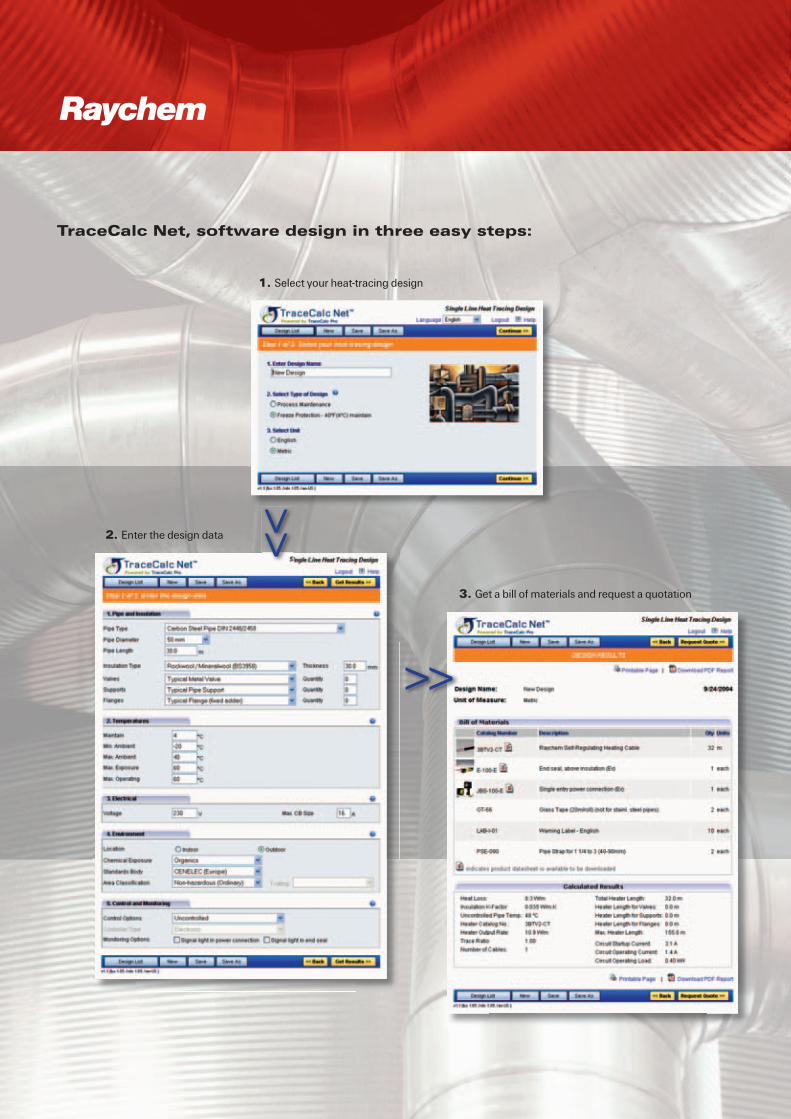
1. Select your heat-tracing design
2. Enter the design data
3. Get a bill of materials and request a quotation
TraceCalc Net, software design in three easy steps:
R

... with easy project design
1>>
2>>
3>>
We manage the heat you need...
Follow this design guideto get to the right solution for your application. This paper guide offers the benefit that it is fast and easy to use at any location where you may need it. First select the correct heating cable, then take care of the electrical design and select the components and accessories to complete your heat-tracing system.
Or let us do the design for youSimply complete the sheet provided at the end of this guide and fax it back to your Tyco Thermal Controls representative who will provide you with a bill of materials and pricing as soon as possible.
Use our software design toolsTraceCalc Net or TraceCalc Pro to generate a complete bill of materials, design summary and line list for your heat-tracing system. Both offer the possibility to do designs for use in hazardous or non-hazardous areas and for frost protection or temperature maintenance. With TraceCalc Net selecting the appropriate industrial pipe heat-tracing products is easy.The simple 3-step design process consists of:1. Select your heat-tracing design 2. Enter the design data 3. Get a bill of materials and request a quotation Register for this online design tool at:www.tycothermal.com/europe/english/heating/registration
For heat-tracing in industrial applications, TraceCalc Pro provides design calculations such as pipe heat loss, number of circuits, electri-cal loads and maximum temperatures, automated heating cable and component selection, recommendations for control and monitoring selection, and much more.It provides easy-to-use standard reports and last but not least, its powerful features help you obtain the best heat-tracing solution for your particular project. With TraceCalc Pro, Tyco Thermal Controls provides you with an un-precedented design tool giving you an optimal heat-tracing solution. Please contact your Tyco Thermal Controls representative for more information.

Our Raychem self-regulating heat-tracing system is …
… Super Safe
• Raychem self-regulating heat-tracing cables are certified for unconditional T-rating in accordance with European Standard EN 50 014. The temperature of the cable will never exceed its T-class temperature.
• The self-regulating principle ensures that the cable senses overlaps. It regu-lates its heat accordingly and prevents any heat build-up or burn out. Furthermore, complex shapes like valves, flanges or pipe supports are easily traced with this system.
… Cost Saving
• The cable is easy to tee, splice, install and repair. No special skills are re-quired, resulting in reduced installation time.
• Due to its self-regulating principle, this system saves energy and thus opera-tional costs.
• The system requires a minimum of maintenance and is fully resistant to all pipe maintenance procedures.
• To easily accommodate design changes on site, the cable can be cut-to-length when being installed.
We manage the heat you need...
... with a ‘high performance’ heat-tracing system
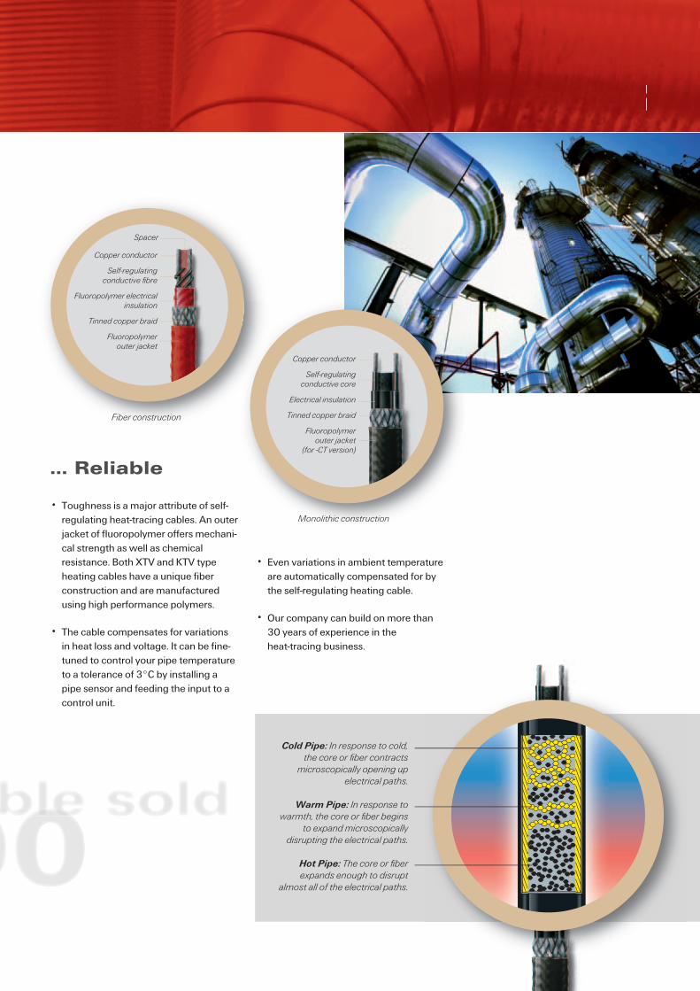
… Reliable
• Toughness is a major attribute of self-regulating heat-tracing cables. An outer jacket of fluoropolymer offers mechani-cal strength as well as chemical resistance. Both XTV and KTV type heating cables have a unique fiber construction and are manufactured using high performance polymers.
• The cable compensates for variations in heat loss and voltage. It can be fine-tuned to control your pipe temperature to a tolerance of 3°C by installing a pipe sensor and feeding the input to a control unit.
• Even variations in ambient temperature are automatically compensated for by the self-regulating heating cable.
• Our company can build on more than 30 years of experience in the heat-tracing business.
Cold Pipe: In response to cold, the core or fi ber contracts
microscopically opening upelectrical paths.
Warm Pipe: In response to warmth, the core or fi ber begins
to expand microscopicallydisrupting the electrical paths.
Hot Pipe: The core or fi berexpands enough to disrupt
almost all of the electrical paths.
Copper conductor
Self-regulatingconductive fi bre
Fluoropolymer electrical insulation
Tinned copper braid
Fluoropolymerouter jacket
Spacer
Fiber construction
Copper conductor
Self-regulating conductive core
Electrical insulation
Tinned copper braid
Fluoropolymer outer jacket
(for -CT version)
Monolithic construction
R

6
How to select and design the heat-tracing system for pipes
This Design Guide outlines a simple procedure for designing and selecting a complete heat-tracing system using BTV, QTVR, XTV or KTV heating cables.
By following the design steps in the 3 sections, a bill of materials can be easily pro-duced which includes the heating cable type, length, components and accessories needed to install the heat-tracing system correctly.
1.0 Heating cable selection 6
2.0 Electrical design 11
3.0 Components and accessories selection 13
InstallationTyco Thermal Controls heat-tracing systems must be installed following Tyco Thermal Controls guidelines. Contact your Tyco Thermal Controls representative for a copy of the installation manual. All components are supplied with easy-to-follow instructions.
Additional informationFull technical information on components and heating cables can be found in our Technical Databook. Combined with the installation instructions this supplements the information in this guide. These documents are available from your local Tyco Thermal Controls representative and from the Tyco Thermal Controls website (www.tycothermal.com).
Heat-Tracing Design Guide
1.0 Heating cable selectionTo select the correct heating cable determine• Pipe or tubing diameter• Thermal insulation thickness• Tm: Maintain Temperature (desired fluid temperature)
Example: Fluid: Process liquid, steam-cleaned Line size: NB 50 mm Insulation thickness: 50 mm Tm: 50°C
Thermal insulation thickness
Pipe or tubingdiameter
+20+10
0-10-20
1007550250
Maintain temperature
Minimum ambient temperature
Heating Cable Selection
1. Determine heat loss
2. Select heating cable family
3. Select heating cable
4. Determine heating cable length
Heat-Tracing Design Guide
7
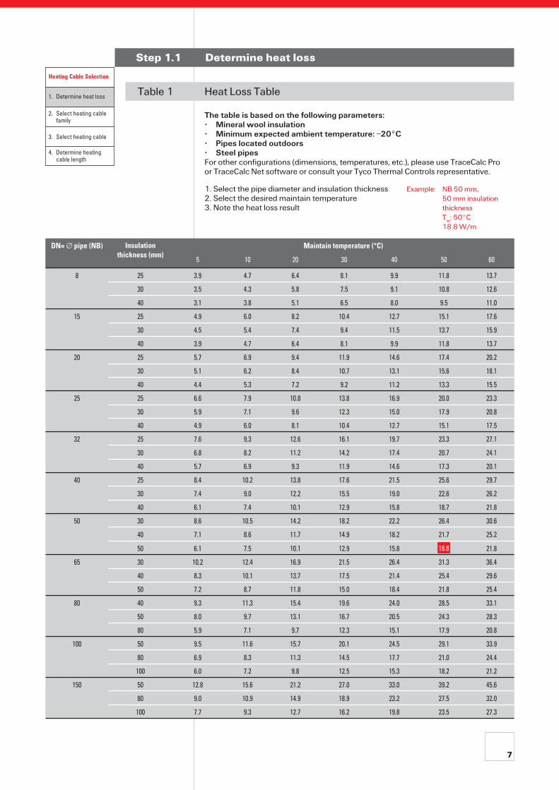
Step 1.1 Determine heat loss
DN= ∅ pipe (NB) Insulation thickness (mm)
Maintain temperature (°C)
5 10 20 30 40 50 60
8 25 3.9 4.7 6.4 8.1 9.9 11.8 13.7
30 3.5 4.3 5.8 7.5 9.1 10.8 12.6
40 3.1 3.8 5.1 6.5 8.0 9.5 11.0
15 25 4.9 6.0 8.2 10.4 12.7 15.1 17.6
30 4.5 5.4 7.4 9.4 11.5 13.7 15.9
40 3.9 4.7 6.4 8.1 9.9 11.8 13.7
20 25 5.7 6.9 9.4 11.9 14.6 17.4 20.2
30 5.1 6.2 8.4 10.7 13.1 15.6 18.1
40 4.4 5.3 7.2 9.2 11.2 13.3 15.5
25 25 6.6 7.9 10.8 13.8 16.9 20.0 23.3
30 5.9 7.1 9.6 12.3 15.0 17.9 20.8
40 4.9 6.0 8.1 10.4 12.7 15.1 17.5
32 25 7.6 9.3 12.6 16.1 19.7 23.3 27.1
30 6.8 8.2 11.2 14.2 17.4 20.7 24.1
40 5.7 6.9 9.3 11.9 14.6 17.3 20.1
40 25 8.4 10.2 13.8 17.6 21.5 25.6 29.7
30 7.4 9.0 12.2 15.5 19.0 22.6 26.2
40 6.1 7.4 10.1 12.9 15.8 18.7 21.8
50 30 8.6 10.5 14.2 18.2 22.2 26.4 30.6
40 7.1 8.6 11.7 14.9 18.2 21.7 25.2
50 6.1 7.5 10.1 12.9 15.8 21.8
65 30 10.2 12.4 16.9 21.5 26.4 31.3 36.4
40 8.3 10.1 13.7 17.5 21.4 25.4 29.6
50 7.2 8.7 11.8 15.0 18.4 21.8 25.4
80 40 9.3 11.3 15.4 19.6 24.0 28.5 33.1
50 8.0 9.7 13.1 16.7 20.5 24.3 28.3
80 5.9 7.1 9.7 12.3 15.1 17.9 20.8
100 50 9.5 11.6 15.7 20.1 24.5 29.1 33.9
80 6.9 8.3 11.3 14.5 17.7 21.0 24.4
100 6.0 7.2 9.8 12.5 15.3 18.2 21.2
150 50 12.8 15.6 21.2 27.0 33.0 39.2 45.6
80 9.0 10.9 14.9 18.9 23.2 27.5 32.0
100 7.7 9.3 12.7 16.2 19.8 23.5 27.3
Table 1 Heat Loss Table The table is based on the following parameters: • Mineral wool insulation • Minimum expected ambient temperature: –20°C • Pipes located outdoors • Steel pipes For other configurations (dimensions, temperatures, etc.), please use TraceCalc Pro or TraceCalc Net software or consult your Tyco Thermal Controls representative.
1. Select the pipe diameter and insulation thickness Example: NB 50 mm, 2. Select the desired maintain temperature 50 mm insulation 3. Note the heat loss result thickness Tm: 50°C 18.8 W/m
Heating Cable Selection
1. Determine heat loss
2. Select heating cable family
3. Select heating cable
4. Determine heating cable length
18.8
8
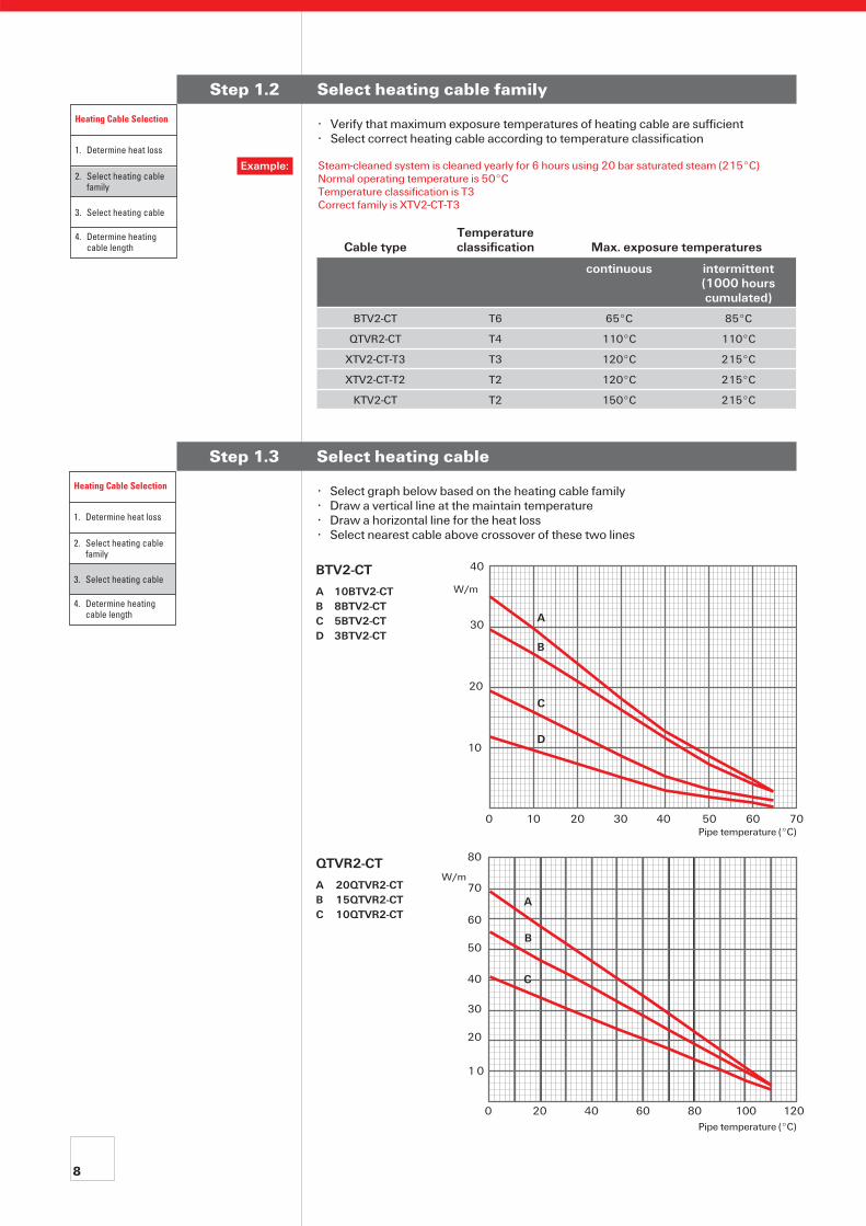
Step 1.2 Select heating cable family
• Verify that maximum exposure temperatures of heating cable are sufficient• Select correct heating cable according to temperature classification
Cable typeTemperatureclassification Max. exposure temperatures
continuous intermittent(1000 hourscumulated)
BTV2-CT T6 65°C 85°C
QTVR2-CT T4 110°C 110°C
XTV2-CT-T3 T3 120°C 215°C
XTV2-CT-T2 T2 120°C 215°C
KTV2-CT T2 150°C 215°C
Steam-cleaned system is cleaned yearly for 6 hours using 20 bar saturated steam (215°C)Normal operating temperature is 50°CTemperature classification is T3Correct family is XTV2-CT-T3
Example:
Step 1.3 Select heating cable
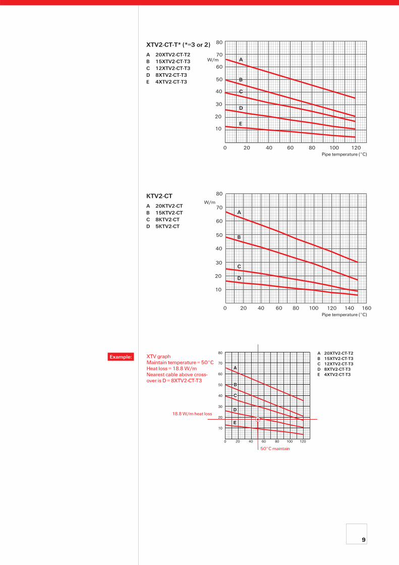
• Select graph below based on the heating cable family• Draw a vertical line at the maintain temperature• Draw a horizontal line for the heat loss• Select nearest cable above crossover of these two lines
Heating Cable Selection
1. Determine heat loss
2. Select heating cable family
3. Select heating cable
4. Determine heating cable length
QTVR2-CT
A 20QTVR2-CTB 15QTVR2-CTC 10QTVR2-CT
BTV2-CT
A 10BTV2-CTB 8BTV2-CTC 5BTV2-CTD 3BTV2-CT
W/m
Pipe temperature (°C)
40
30
20
10
0 10 20 30 40 50 60 70
A
B
C
D
Pipe temperature (°C)
W/m
80
70
60
50
40
30
20
1 0
0 20 40 60 80 100 120
A
B
C
Heating Cable Selection
1. Determine heat loss
2. Select heating cable family
3. Select heating cable
4. Determine heating cable length
9
KTV2-CT
A 20KTV2-CTB 15KTV2-CTC 8KTV2-CTD 5KTV2-CT
Pipe temperature (°C)
XTV2-CT-T* (*=3 or 2)
A 20XTV2-CT-T2B 15XTV2-CT-T3C 12XTV2-CT-T3D 8XTV2-CT-T3E 4XTV2-CT-T3
W/m
0 20 40 60 80 100 120
80
70
60
50
40
20
10
30
C
D
E
B
A
XTV graph Maintain temperature = 50°CHeat loss = 18.8 W/mNearest cable above cross-over is D = 8XTV2-CT-T3
Example:A 20XTV2-CT-T2B 15XTV2-CT-T3C 12XTV2-CT-T3D 8XTV2-CT-T3E 4XTV2-CT-T3
18.8 W/m heat loss
50°C maintain
W/m
Pipe temperature (°C)0 20 40 60 80 100 120
80
70
30
10
20
40
60
50
0 20 40 60 80 100 120 140 160
80
70
30
10
20
40
60
50
A
B
C
D
E
A
C
B
D
10
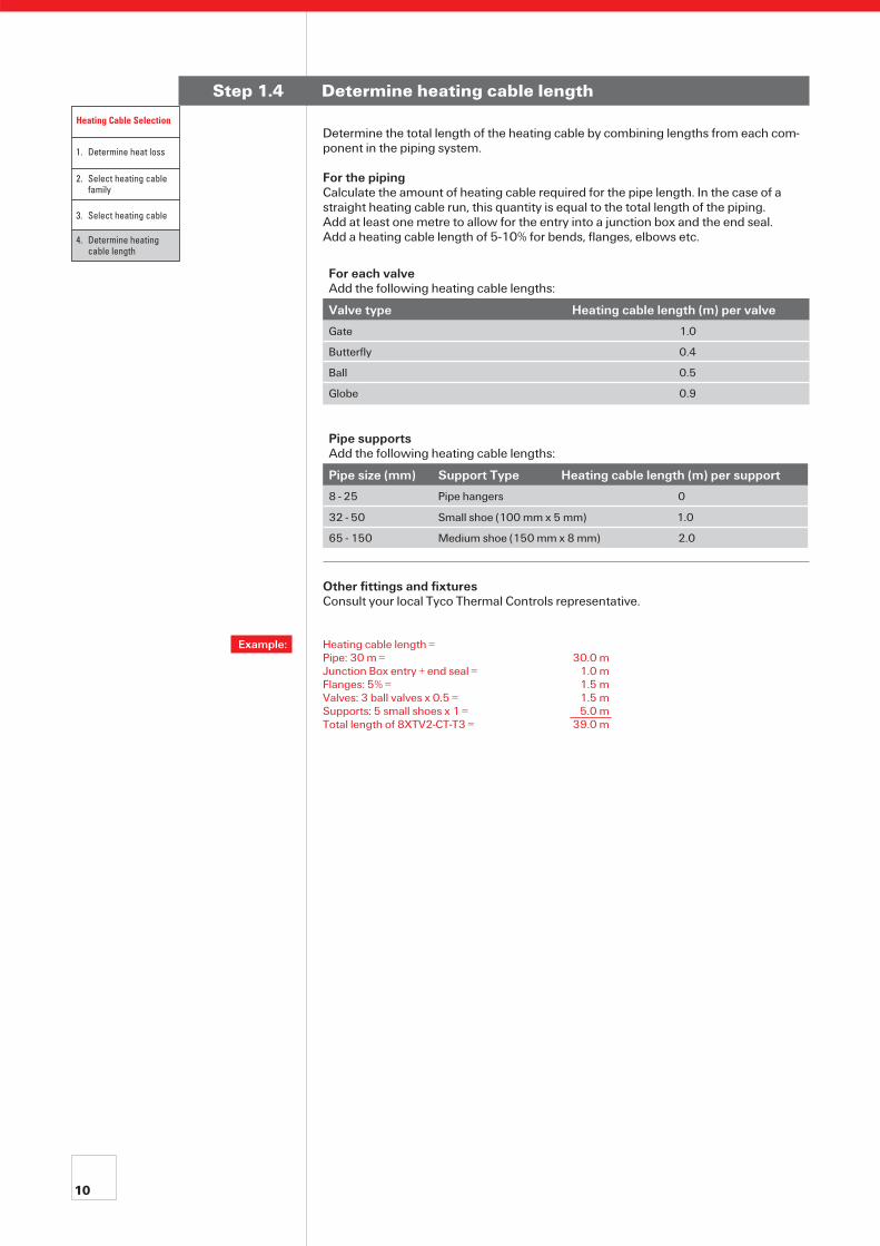
Step 1.4 Determine heating cable length
Determine the total length of the heating cable by combining lengths from each com-ponent in the piping system.
For the pipingCalculate the amount of heating cable required for the pipe length. In the case of a straight heating cable run, this quantity is equal to the total length of the piping.Add at least one metre to allow for the entry into a junction box and the end seal.Add a heating cable length of 5-10% for bends, flanges, elbows etc.
For each valveAdd the following heating cable lengths:
Valve type Heating cable length (m) per valve
Gate 1.0
Butterfly 0.4
Ball 0.5
Globe 0.9
Pipe supportsAdd the following heating cable lengths:
Pipe size (mm) Support Type Heating cable length (m) per support
8 - 25 Pipe hangers 0
32 - 50 Small shoe (100 mm x 5 mm) 1.0
65 - 150 Medium shoe (150 mm x 8 mm) 2.0
Other fittings and fixturesConsult your local Tyco Thermal Controls representative.
Example: Heating cable length = Pipe: 30 m = 30.0 m Junction Box entry + end seal = 1.0 m Flanges: 5% = 1.5 m Valves: 3 ball valves x 0.5 = 1.5 m Supports: 5 small shoes x 1 = 5.0 m Total length of 8XTV2-CT-T3 = 39.0 m
Heating Cable Selection
1. Determine heat loss
2. Select heating cable family
3. Select heating cable
4. Determine heating cable length
11
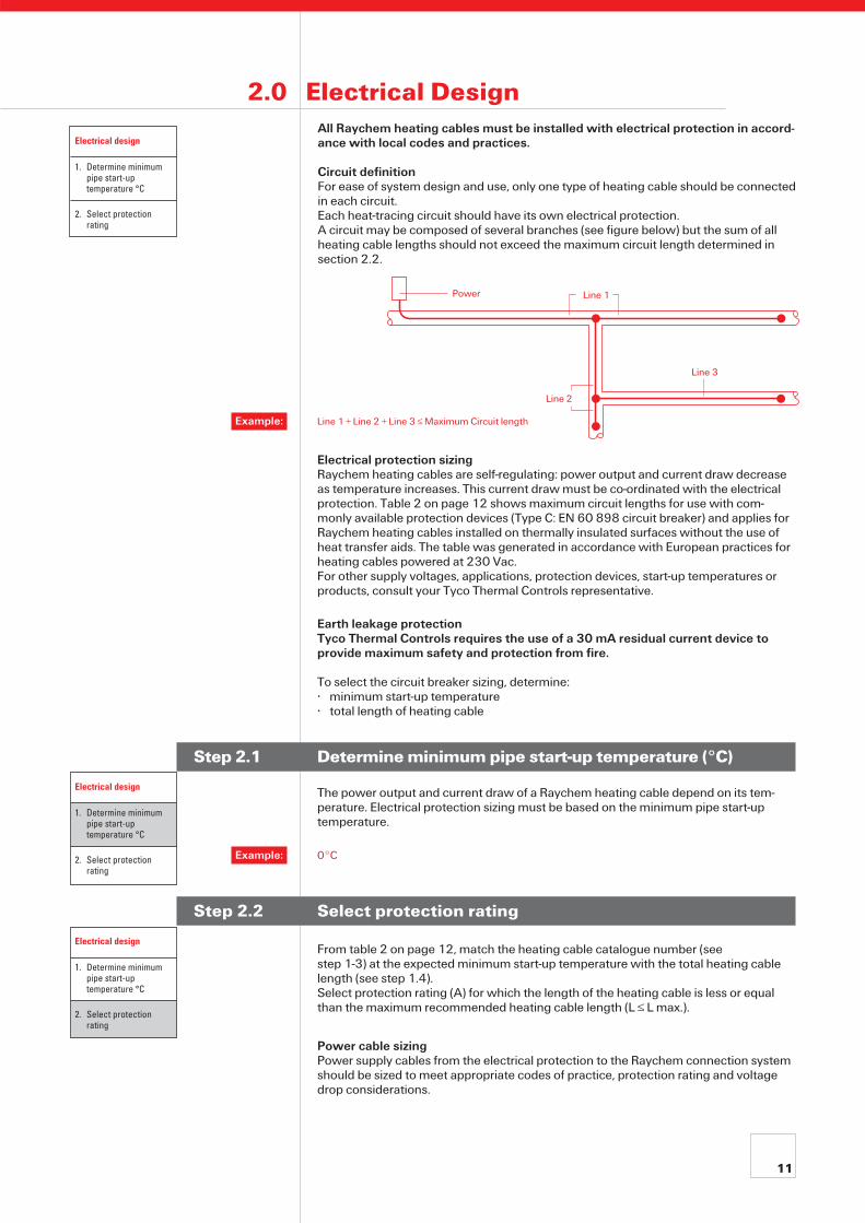
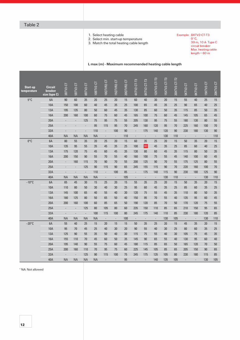
Electrical protection sizingRaychem heating cables are self-regulating: power output and current draw decrease as temperature increases. This current draw must be co-ordinated with the electrical protection. Table 2 on page 12 shows maximum circuit lengths for use with com-monly available protection devices (Type C: EN 60 898 circuit breaker) and applies for Raychem heating cables installed on thermally insulated surfaces without the use of heat transfer aids. The table was generated in accordance with European practices for heating cables powered at 230 Vac. For other supply voltages, applications, protection devices, start-up temperatures or products, consult your Tyco Thermal Controls representative.
Earth leakage protectionTyco Thermal Controls requires the use of a 30 mA residual current device to provide maximum safety and protection from fire.
To select the circuit breaker sizing, determine:• minimum start-up temperature• total length of heating cable
Step 2.1 Determine minimum pipe start-up temperature (°C)
The power output and current draw of a Raychem heating cable depend on its tem-perature. Electrical protection sizing must be based on the minimum pipe start-up temperature.
Step 2.2 Select protection rating
From table 2 on page 12, match the heating cable catalogue number (see step 1-3) at the expected minimum start-up temperature with the total heating cable length (see step 1.4).Select protection rating (A) for which the length of the heating cable is less or equal than the maximum recommended heating cable length (L ≤ L max.).
Power cable sizingPower supply cables from the electrical protection to the Raychem connection system should be sized to meet appropriate codes of practice, protection rating and voltage drop considerations.
2.0 Electrical DesignAll Raychem heating cables must be installed with electrical protection in accord-ance with local codes and practices.
Circuit definitionFor ease of system design and use, only one type of heating cable should be connected in each circuit.Each heat-tracing circuit should have its own electrical protection.A circuit may be composed of several branches (see figure below) but the sum of all heating cable lengths should not exceed the maximum circuit length determined in section 2.2.
Power Line 1
Line 2
Line 3
0°CExample:
Line 1 + Line 2 + Line 3 ≤ Maximum Circuit lengthExample:
Electrical design
1. Determine minimum pipe start-up temperature °C
2. Select protection rating
Electrical design
1. Determine minimum pipe start-up temperature °C
2. Select protection rating
Electrical design
1. Determine minimum pipe start-up temperature °C
2. Select protection rating
12
Table 2 1. Select heating cable 2. Select min. start-up temperature 3. Match the total heating cable length
L max (m) - Maximum recommended heating cable length
Start-up temperature
Circuit breaker
size (type C) 3BTV
2-CT
5BTV
2-CT
8BTV
2-CT
10BT
V2-C
T
10QT
VR2-
CT
15QT
VR2-
CT
20QT
VR2-
CT
4XTV
2-CT
-T3
8XTV
2-CT
-T3
12XT
V2-C
T-T3
15XT
V2-C
T-T3
20XT
V2-C
T-T2
5KTV
2-CT
8KTV
2-CT
15KT
V2-C
T
20KT
V2-C
T
5°C 6A 90 60 35 20 25 20 15 60 40 30 20 15 55 40 25 15
10A 150 100 60 40 45 35 25 100 65 45 35 25 90 65 40 25
13A 195 135 80 50 60 45 35 130 85 60 50 35 115 85 50 35
16A 200 160 100 60 75 60 45 165 100 75 60 45 145 105 65 45
20A - - 125 75 95 75 55 205 130 95 75 55 180 130 80 55
25A - - - 95 115 95 70 245 160 120 95 70 225 160 100 70
32A - - - 110 - 100 90 - 175 140 120 90 230 180 130 90
40A NA NA NA NA - - 110 - - - 130 110 - - - 110
0°C 6A 80 55 35 20 25 20 15 60 35 25 20 15 50 35 20 15
10A 135 95 55 35 45 35 25 100 60 45 35 25 85 60 40 25
13A 175 120 75 45 60 45 35 130 80 60 45 35 115 80 50 35
16A 200 150 90 55 70 55 40 160 100 75 55 45 140 100 60 45
20A - 160 115 70 90 70 55 200 125 90 70 55 175 125 80 55
25A - - 125 90 115 90 65 245 155 115 90 70 220 160 100 70
32A - - - 110 - 100 85 - 175 140 115 90 230 180 125 90
40A NA NA NA NA - - 105 - - - 130 110 - - 130 110
–10°C 6A 65 45 30 15 25 20 15 55 35 25 20 15 50 35 20 15
10A 110 80 50 30 40 30 25 95 60 45 35 25 85 60 35 25
13A 145 100 65 40 55 40 30 120 75 55 45 35 110 80 50 35
16A 180 125 80 50 65 50 40 150 95 70 55 40 135 95 60 45
20A 200 160 100 60 85 65 50 190 120 85 70 50 170 120 75 55
25A - - 125 80 105 80 60 235 150 110 85 65 210 150 95 65
32A - - - 100 115 100 80 245 175 140 110 85 230 180 120 85
40A NA NA NA NA - - 100 - - - 130 105 - - 130 110
–20°C 6A 55 40 25 15 20 15 15 50 35 25 20 15 45 35 20 15
10A 95 70 45 25 40 30 20 90 55 40 30 25 80 60 35 25
13A 125 90 55 35 50 40 30 115 75 55 40 30 105 75 45 35
16A 155 110 70 45 60 50 35 145 90 65 55 40 130 95 60 40
20A 195 140 90 55 75 60 45 180 115 85 65 50 165 120 70 50
25A 200 160 110 70 95 75 60 225 145 105 85 65 205 150 90 65
32A - - 125 90 115 100 75 245 175 135 105 80 230 180 115 85
40A NA NA NA NA - - 95 - - 140 135 105 - - 130 105
* NA: Not allowed
60
Example: 8XTV2-CT-T3 0°C, 39 m, 10 A Type C circuit breaker Max. heating cable length = 60 m
13
®
Components and accessories
1. Power connections
2. Splices and Tees
3. End seals
4. Thermostats
5. Accessories
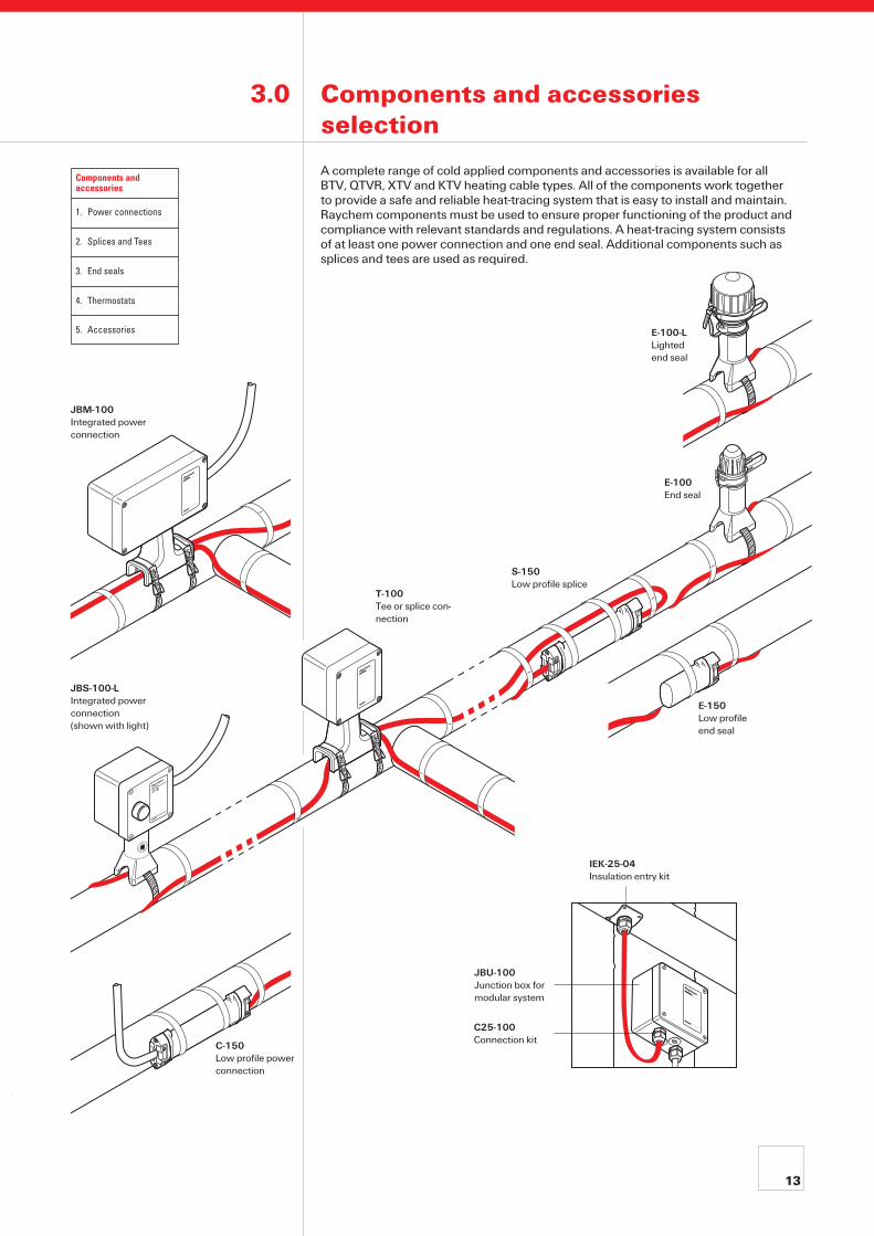
3.0 Components and accessories selection
A complete range of cold applied components and accessories is available for all BTV, QTVR, XTV and KTV heating cable types. All of the components work together to provide a safe and reliable heat-tracing system that is easy to install and maintain. Raychem components must be used to ensure proper functioning of the product and compliance with relevant standards and regulations. A heat-tracing system consists of at least one power connection and one end seal. Additional components such as splices and tees are used as required.
T-100 Tee or splice con-nection
JBM-100Integrated power connection
JBS-100-LIntegrated power connection(shown with light)
E-100-L Lighted end seal
E-100 End seal
S-150Low profile splice
E-150Low profile end seal
C25-100Connection kit
IEK-25-04Insulation entry kit
JBU-100Junction box for modular system
C-150Low profile power connection

14
Power connections
Power connections may be mounted on or off the pipe. For pipe mounted applications, select one of the integrated components below. For mounting off the pipe, select a separate junction box and the necessary connection kits and insulation entry kits from the modular components table on the next page.The kits can be used with Raychem industrial heating cables: BTV, QTVR, XTV and KTV.The power connections JBS, JBM and JBU can also be ordered with a green light for simple indication if power is on.
Integrated components
Integrated components combine the functions of the junction box, connection, insula-tion entry, and support bracket. These components provide full protection of the heating cable for safe operation. The cold-applied core sealing and innovative WAGO cage clamp terminals ensure reliable connections and significantly reduce installation time. The integrated components are designed for industrial applications and are ap-proved for use in hazardous areas (EEx e). Threads are metric (M25).
Above the insulation
JBS-100-E Integrated power connection for 1 heating cable. Cold applied. One power cable gland included. Requires 1 pipe strap, to be ordered separately.Part number: 829939-000With green light, order reference: JBS-100-L-E (P/N 054363-000)
JBS-100-EP Integrated power connection for 1 heating cable. Includes earth plate and earth stud for use with armoured cables. Cold applied. Requires 1 pipe strap and 1 metal power cable gland to be ordered separately. Part number: 158251-000
With green light, order reference: JBS-100-L-EP (P/N 075249-000)
JBM-100-E Integrated power connection for up to 3 heating cables.May also be used for tee and splice connections. Cold applied. One power cable gland included.Requires 2 pipe straps, to be ordered separately.Part number: 831519-000With green light, order reference: JBM-100-L-E(P/N 395855-000)
JBM-100-EP Integrated power connection for up to 3 heating cables. Includes earth plate and earth stud for use with armoured cables. May also be used for tee and splice connections. Cold applied. Requires 2 pipe straps and 1 metal power cable gland to be ordered separately. Part number: 986415-000With green light, order reference: JBM-100-L-EP (P/N 300273-000)
Under the insulation
C-150-E Low profile power connection for 1 heating cable.Maximum load of 25ACold appliedSuitable for non-armoured power cables up to 2.5 mm2
with stranded copper conductorsC-150-E is used as a connector:
• where connection to a junction box is difficult e.g. because of space limitations
• on instrument lines or loading arms • where installation of under insulation components is
preferred • as a cost effective alternative for JBS-100-E on short lines
Part number: 073704-000
®
Components and accessories
1. Power connections
2. Splices and Tees
3. End seals
4. Thermostats
5. Accessories
15
Splices and Tees
For in-line joining or making T-connections of the heating cables. Approved for use in hazardous areas (EEx e).
Above the insulation
JBM-100-E For making splice or tee connections with terminals above the insulation.Cold applied.Requires 2 pipe straps, to be ordered separately.Part number: 831519-000With internal earth plate and earth stud, order reference: JBM-100-EP (P/N 986415-000)
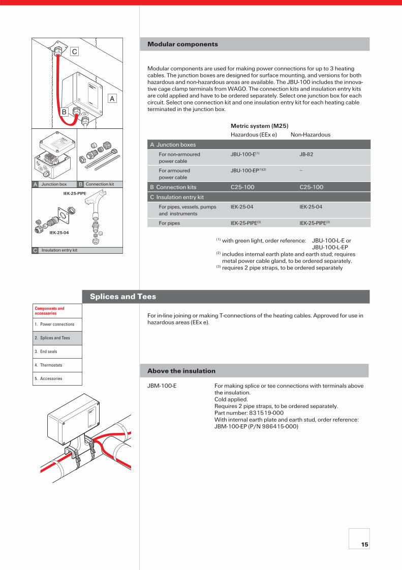
Modular components
Modular components are used for making power connections for up to 3 heating cables. The junction boxes are designed for surface mounting, and versions for both hazardous and non-hazardous areas are available. The JBU-100 includes the innova-tive cage clamp terminals from WAGO. The connection kits and insulation entry kits are cold applied and have to be ordered separately. Select one junction box for each circuit. Select one connection kit and one insulation entry kit for each heating cable terminated in the junction box.
Metric system (M25) Hazardous (EEx e) Non-Hazardous
A Junction boxes
For non-armouredpower cable
JBU-100-E(1) JB-82
For armoured power cable
JBU-100-EP(1)(2) –
B Connection kits C25-100 C25-100
C Insulation entry kit
For pipes, vessels, pumps and instruments
IEK-25-04 IEK-25-04
For pipes IEK-25-PIPE(3) IEK-25-PIPE(3)
(1) with green light, order reference: JBU-100-L-E or JBU-100-L-EP (2) includes internal earth plate and earth stud; requires metal power cable gland, to be ordered separately. (3) requires 2 pipe straps, to be ordered separately
B
A
C
RJBU-100
600
Do not open while energised
Nicht unter Spannung öffnen
Ne pas ouvrir sous tension
BTVEEX de II C T6
PTB Nr. Ex-95.D.1002 X
EEx e II T6
BAS No. Ex 96D3199X
QTVREEX de II C T4
PTB Nr. Ex-95.D.1003 X
EEx e II T4
BAS No. Ex 96D3198X
KTVEEX de II C T2
PTB Nr. Ex-95.D.1004 X
EEx e II 226°C (T2)BAS No. Ex 96D3200X
4, 8, 12, 15XTV-T3
EEX de II C T3
PTB Nr. Ex-95.D.1005 X
EEx e II T3
BAS No. Ex 96D3435X
20XTV-T2EEX de II C T2
PTB Nr. Ex-95.D.1005 X
EEx e II 250°C (T2)BAS No. Ex 95D3435XPR551647
II 2 G EEx e II
PTB 97 ATEX 1058 U
BA
C
IEK-25-04
Junction box
Insulation entry kit
Connection kit
Components and accessories
1. Power connections
2. Splices and Tees
3. End seals
4. Thermostats
5. Accessories
IEK-25-PIPE
16
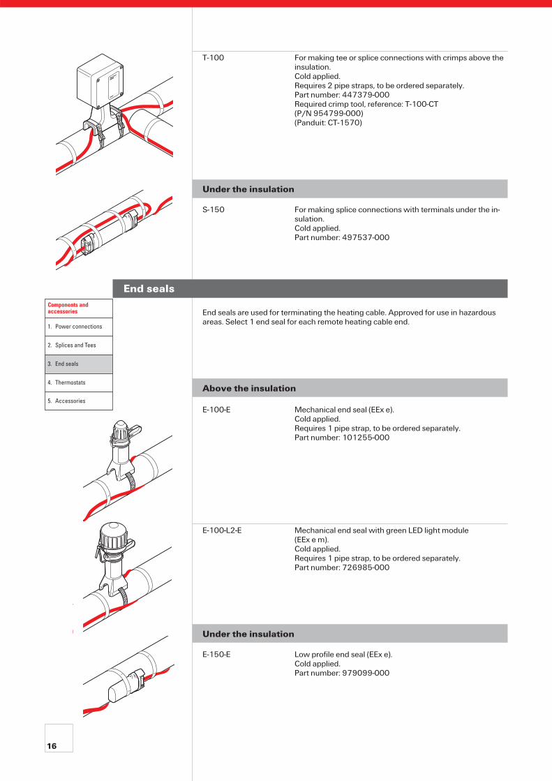
End seals are used for terminating the heating cable. Approved for use in hazardous areas. Select 1 end seal for each remote heating cable end.
Above the insulation
E-100-E Mechanical end seal (EEx e). Cold applied. Requires 1 pipe strap, to be ordered separately.Part number: 101255-000
E-100-L2-E Mechanical end seal with green LED light module (EEx e m). Cold applied. Requires 1 pipe strap, to be ordered separately.Part number: 726985-000
Under the insulation
E-150-E Low profile end seal (EEx e).Cold applied. Part number: 979099-000
End seals
T-100 For making tee or splice connections with crimps above the insulation. Cold applied. Requires 2 pipe straps, to be ordered separately.Part number: 447379-000Required crimp tool, reference: T-100-CT (P/N 954799-000)(Panduit: CT-1570)
Under the insulation
S-150 For making splice connections with terminals under the in-sulation. Cold applied.Part number: 497537-000
Components and accessories
1. Power connections
2. Splices and Tees
3. End seals
4. Thermostats
5. Accessories
17
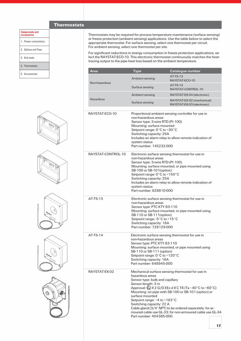
Thermostats
Thermostats may be required for process temperature maintenance (surface sensing) or freeze protection (ambient sensing) applications. Use the table below to select the appropriate thermostat. For surface sensing, select one thermostat per circuit. For ambient sensing, select one thermostat per site.
For significant reductions in energy consumption in freeze protection applications, se-lect the RAYSTAT-ECO-10. This electronic thermostat continuously matches the heat-tracing output to the pipe heat loss based on the ambient temperature.
Area Type Catalogue number
Non-hazardousAmbient sensing
AT-TS-13RAYSTAT-ECO-10
Surface sensingAT-TS-14RAYSTAT-CONTROL-10
HazardousAmbient sensing RAYSTAT-EX-04 (electronic)
Surface sensingRAYSTAT-EX-02 (mechanical)RAYSTAT-EX-03 (electronic)
RAYSTAT-ECO-10 Proportional ambient sensing controller for use innon-hazardous areasSensor type: 3-wire RTD (Pt 100)Mounting: surface mountedSetpoint range: 0°C to +30°CSwitching capacity: 25AIncludes an alarm relay to allow remote indication ofsystem statusPart number: 145232-000
RAYSTAT-CONTROL-10 Electronic surface sensing thermostat for use innon-hazardous areasSensor type: 3-wire RTD (Pt 100)Mounting: surface mounted, or pipe mounted using SB-100 or SB-101(option)Setpoint range: 0°C to +150°CSwitching capacity: 25AIncludes an alarm relay to allow remote indication ofsystem statusPart number: 828810-000
AT-TS-13 Electronic surface sensing thermostat for use innon-hazardous areasSensor type: PTC KTY 83-110Mounting: surface mounted, or pipe mounted using SB-110 or SB-111(option)Setpoint range: -5°C to +15°CSwitching capacity: 16APart number: 728129-000
AT-TS-14 Electronic surface sensing thermostat for use innon-hazardous areasSensor type: PTC KTY 83-110Mounting: surface mounted, or pipe mounted using SB-110 or SB-111 (option)Setpoint range: 0°C to +120°CSwitching capacity: 16APart number: 648945-000
RAYSTAT-EX-02 Mechanical surface sensing thermostat for use in hazardous areas Sensor type: bulb and capillary Sensor length: 3 m Approval: II 2 G/D EEx d II C T6 (Ta –40°C to +60°C) Mounting: on pipe with SB-100 or SB-101 (option) or surface mounted Setpoint range: –4 to +163°C Switching capacity: 22 A Cable gland (3/4" NPT) to be ordered separately: for ar-moured cable use GL-33; for non-armoured cable use GL-34Part number: 404385-000
RAYSTAT-CONTROL-10
6030
090
120
C°
6030
090
120
C°
Components and accessories
1. Power connections
2. Splices and Tees
3. End seals
4. Thermostats
5. Accessories

18
Accessories
Stainless steel support brackets
Support brackets are used to fix equipment such as thermostats or junction boxes on pipes. Support brackets require additional pipe straps which are to be ordered sepa-rately. They include a set of M6 and/or M4 fixing screws, nuts, washers and spring lock washers for the fixation of one junction box or thermostat. The table below out-lines the typical compatibility of each bracket with relevant equipment, for other equip-ment please contact your Tyco Thermal Controls representative.
SB-100 SB-101 SB-110 SB-111AT-TS-13 x x x x
AT-TS-14 x x x x
JBU-100-E x x
JBU-100-EP x x
RAYSTAT-CONTROL-10 x x
RAYSTAT-ECO-10 x x
RAYSTAT-EX-02 x x x x
RAYSTAT-EX-03 x x
RAYSTAT-EX-04 x x
Technical data
plate size (mm) X x Y 160 x 230 160 x 160 130 x 130 130 x 130
distance pipe-plate (mm) 100 160 100 100
number of pipe straps required
2 2 1 2
Part number 192932-000 990944-000 707366-0000 579796-000
RAYSTAT-EX-03 Electronic surface sensing thermostat for use in hazardous areas Sensor type: 2 wire RTD (Pt 100) Sensor length: 2 m Approval: II 2 G/D T=85°C EEx emia IIC T6 (Ta –50°C to +55°C)Mounting: on pipe with SB-100 or SB-101 (option) or surface mounted Setpoint range: 0 to +499°C Switching capacity: 16 APart number: 333472-000
RAYSTAT-EX-04 Electronic ambient sensing thermostat for use in hazardous areas Approval: II 2 G/D T=85°C EEx emia IIC T6 (Ta –50°C to +55°C)Mounting: on pipe with SB-100 or SB-101 (option) or surface mounted Setpoint range: 0 to +49°C Switching capacity: 16 APart number: 462834-000
Control and Monitoring products
In addition to products in this document, Tyco Thermal Controls also offers control & monitoring units ranging from single up to 130 circuits.For further information, refer to the Technical Databook for Industrial Heat-Tracing Systems, visit our website (www.tycothermal.com) or contact your Tyco Thermal Controls representative.
MoniTrace 200N
PWR
INT ADR
NETADR
0
RTD1RTD2
RTD3RTD4
RTD5RTD6
RTD7RTD8
MoniTrace
System
RMM
200N
Voltage Selector
AC 100-120 V 1
10
AC 208-240 V 2
20
NETADR
INTADR
PWR
XMT RCV
RS485
S
S+ -
+ -
RTD Wiring
LISTED
80BJ
OPEN ENERGY
MANAGEMENT SYSTEM
ACCESSORY
76LJ
SIGNAL SYSTEM UNIT
50/60 Hz, 5W
Max. ambient temperature: 6
0 C
APPROVED
Install per Raychem's RMM Installation Instruction Manual
Raychem Montage- und Betriebsanleitung beachten
Suivre attentivement les instructions d'installation de Raychem
Fuse N
200mA
ON
TxD
I/O RUN
I/O ERR
RxD
CRC
750-312
Address x 1
x 10 +
–
2
Components and accessories
1. Power connections
2. Splices and Tees
3. End seals
4. Thermostats
5. Accessories
19
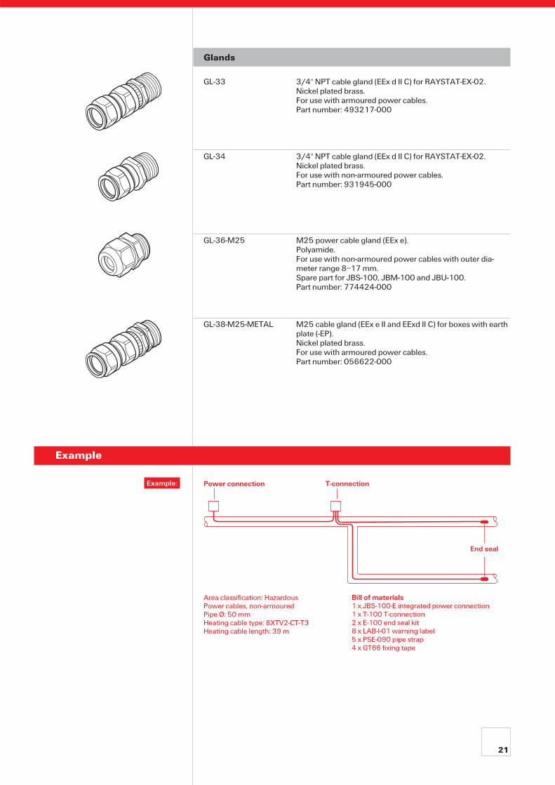
Pipe straps
Are used for fixing components. Select the appropriate pipe strap (stainless steel) ac-cording to the pipe diameter. For JBS-100, JBM-100, E-100, E-100-L, T-100 and IEK-25-PIPE, add 25 mm to the pipe diameter.
Pipe outer diameter in mm (inches) Pipe strap Part number
20-47 (1/2" - 11/4") PSE-047 700333-000
40-90 (11/4" - 3") PSE-090 976935-000
60-288 (2" - 10") PSE-280 664775-000
60-540 (2" - 20") PSE-540 364489-000
Warning labels
Warning labels indicate the presence of electrical heat-tracing under the insulation of the pipe or other equipment. (min. of 1 label per 5 m of heat-tracing line).
Language Label reference PN
Croatian ETL-HR 938764-000
Czech ETL-CZ 731605-000
Danish ETL-DK C97690-000
Dutch LAB-I-23 749153-000
English LAB-I-01 938-947-000
Finnish LAB-ETL-SF 756479-000
French LAB-I-05 883061-000
German / French / Italian LAB-ETL-CH 148648-000
German ETL-G 597779-000
Hungarian LAB-ETL-H 623725-000
Italian ETL-I C97688-000
Latvian LAB-I-32 841822-000
Lithuanian LAB-ETL-LIT 105300-000
Norwegian ETL-N C97689-000
Norwegian / English LAB-ETL-NE 165899-000
Polish ETL-PL 258203-000
Portugese LAB-ETL-POR 945960-000
Romanian ETL-RO 902104-000
Russian LAB-ETL-R 574738-000
Slovenian ETL-SLO 538156-000
Spanish ETL-Spanish C97686-000
Swedish LAB-ETL-S 691703-000
Thermostat kit
Kit with supplementary terminals to connect thermostat
type RAYSTAT-EX-02 to the junction boxes JBS, JBM and JBU.The kit includes 2 terminals WAGO 284 series (1 x L,1 x PE) and 1 power cable gland GL-36-M25.Part number: 966659-000
HWA-WAGO-TSTAT-KIT

20
Fixing tape
Select the tape according to the pipe material. Applied in 3 turns every 300 mm across heating cable. Determine the quantity from the table below.
Number of rolls = Total pipe length m of pipe per roll
Add another 20% to allow for fixing the heating cable on valves, flanges, etc. if appropriate.
GT-66 Standard glass cloth tape. For carbon steel pipes.20 m per roll.Part number: C77220-000
GS-54 Glass cloth tape with low halogen content.For stainless steel pipes.16 m per roll.Part number: C77221-000
For the use of aluminium tape as heat transfer aid, use TraceCalc Pro or TraceCalc Net or consult your Raychem representative.
Pipe size mm inches
GT66m of pipe per roll
GS54m of pipe per roll
8 1/4" 46.5 37.2
15 1/2" 29.9 23.9
20 3/4" 23.8 19.1
25 1" 19.1 15.2
32 11/4" 15.1 12.1
40 11/2" 13.2 10.5
50 2" 10.6 8.4
65 21/2" 8.7 7.0
80 3" 7.2 5.7
100 4" 5.6 4.5
150 6" 3.8 3.0
Protective grommet
G-02 Protective grommet to protect the heating cable from mechanical damage (e.g. at a sharp edge). Supplied in 1 m sections, to be cut to length.Part number: 412549-000
21
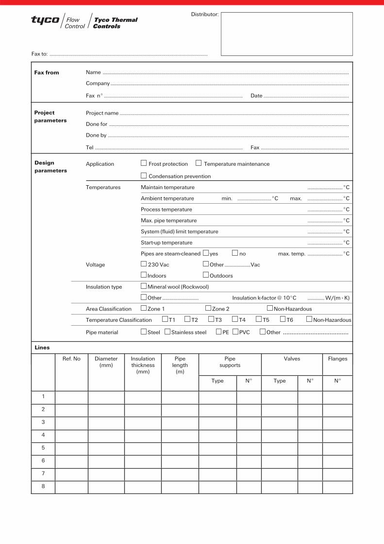
Glands
GL-33 3/4" NPT cable gland (EEx d II C) for RAYSTAT-EX-02. Nickel plated brass. For use with armoured power cables.Part number: 493217-000
GL-34 3/4" NPT cable gland (EEx d II C) for RAYSTAT-EX-02. Nickel plated brass. For use with non-armoured power cables.Part number: 931945-000
GL-36-M25 M25 power cable gland (EEx e). Polyamide. For use with non-armoured power cables with outer dia-meter range 8–17 mm. Spare part for JBS-100, JBM-100 and JBU-100.Part number: 774424-000
GL-38-M25-METAL M25 cable gland (EEx e II and EExd II C) for boxes with earth plate (-EP).Nickel plated brass.For use with armoured power cables.Part number: 056622-000
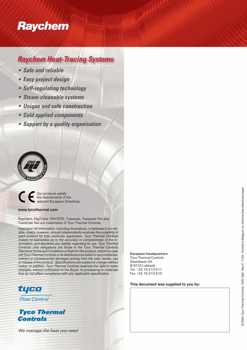
Example
Area classification: HazardousPower cables, non-armouredPipe Ø: 50 mmHeating cable type: 8XTV2-CT-T3Heating cable length: 39 m
Power connection
Bill of materials1 x JBS-100-E integrated power connection1 x T-100 T-connection2 x E-100 end seal kit8 x LAB-I-01 warning label5 x PSE-090 pipe strap4 x GT66 fixing tape
T-connection
End seal
Example:
Distributor:
Ref. No Diameter(mm)
Insulationthickness
(mm)
Pipelength
(m)
Pipesupports
Valves Flanges
Type N° Type N° N°
1
2
3
4
5
6
7
8
Name ..............................................................................................................................................................................................
Company ........................................................................................................................................................................................
Fax n° ........................................................................................................... Date ..................................................................
Fax from
Project name .................................................................................................................................................................................
Done for .........................................................................................................................................................................................
Done by ..........................................................................................................................................................................................
Tel .................................................................................................................. Fax ....................................................................
Project parameters
Application Frost protection Temperature maintenance
Condensation prevention
Designparameters
Temperatures Maintain temperature ...........................°C
Ambient temperature min. ..........................°C max. ...........................°C
Process temperature ...........................°C
Max. pipe temperature ...........................°C
System (fluid) limit temperature ...........................°C
Start-up temperature ...........................°C
Pipes are steam-cleaned yes no max. temp. ...........................°C
Voltage 230 Vac Other ....................Vac
Location Indoors Outdoors
Insulation type Mineral wool (Rockwool)
Other ............................ Insulation k-factor @ 10°C ............. W/(m · K)
Area Classification Zone 1 Zone 2 Non-Hazardous
Temperature Classification T1 T2 T3 T4 T5 T6 Non-Hazardous
Pipe material Steel Stainless steel PE PVC Other ......................................
Lines
Fax to: ..........................................................................................................................
Important: All information, including illustrations, is believed to be reli-able. Users, however, should independently evaluate the suitability of each product for their particular application. Tyco Thermal Controls makes no warranties as to the accuracy or completeness of the in-formation, and disclaims any liability regarding its use. Tyco Thermal Controls’ only obligations are those in the Tyco Thermal Controls Standard Terms and Conditions of Sale for this product, and in no case will Tyco Thermal Controls or its distributors be liable for any incidental, indirect or consequential damages arising from the sale, resale, use or misuse of the product. Specifi cations are subject to change without notice. In addition, Tyco Thermal Controls reserves the right to make changes, without notifi cation to the Buyer, to processing or materials that do not affect compliance with any applicable specifi cation.
Raychem, DigiTrace, RAYSTAT, Tracecalc, Tracecalc Pro and TraceCalc Net are trademarks of Tyco Thermal Controls.
© 2
004
Tyco
The
rmal
Con
trol
s D
OC
-565
Rev
.0 1
1/04
Prin
ted
in B
elgi
um o
n ch
lorin
e-fr
ee b
leac
hed
pape
r.
This document was supplied to you by:
Our products satisfythe requirements of therelevant European Directives.
www.tycothermal.com
European headquarters:Tyco Thermal ControlsStaatsbaan 4AB-3210 LubbeekTel. +32 16 213 511Fax +32 16 213 610
We manage the heat you need
• Safe and reliable
• Easy project design
• Self-regulating technology
• Steam-cleanable systems
• Unique and safe construction
• Cold applied components
• Support by a quality organisation
Raychem Heat-Tracing Systems
R