Embed Size (px)
Citation preview
2
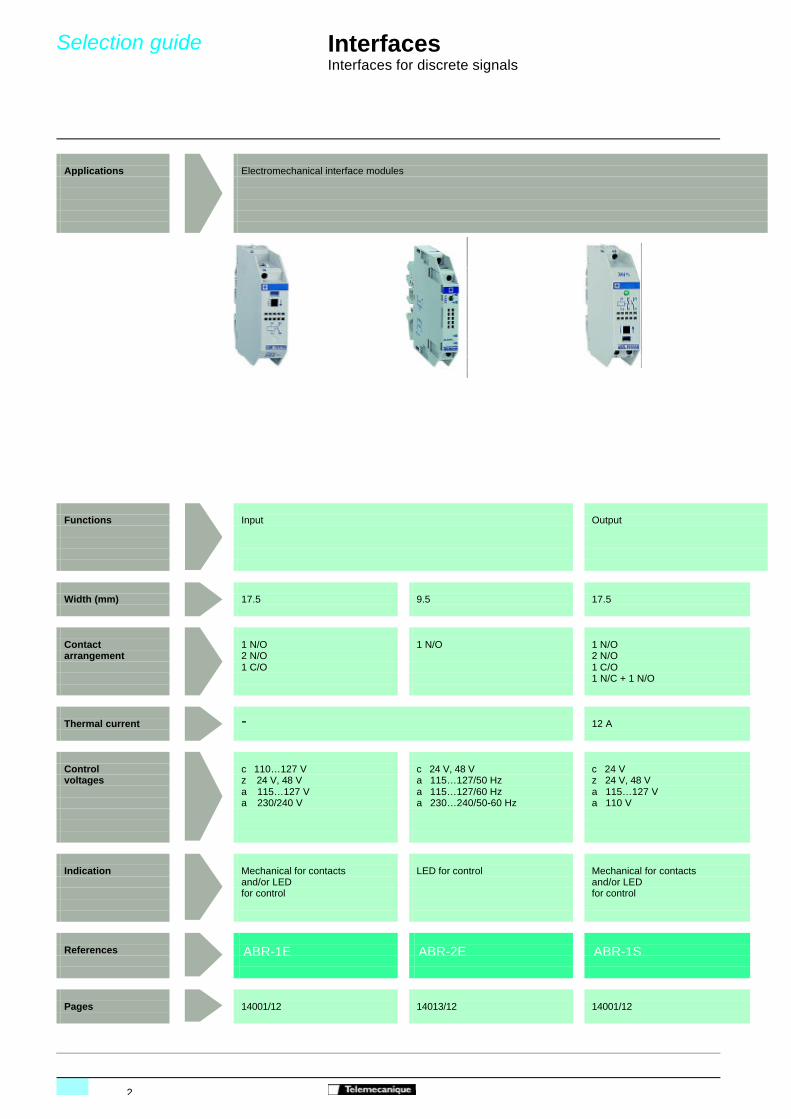
Applications Electromechanical interface modules
Functions Input Output
Width (mm) 17.5 9.5 17.5
Contact 1 N/O 1 N/O 1 N/Oarrangement 2 N/O 2 N/O
1 C/O 1 C/O1 N/C + 1 N/O
Thermal current - 12 A
Control c 110…127 V c 24 V, 48 V c 24 Vvoltages z 24 V, 48 V a 115…127/50 Hz z 24 V, 48 V
a 115…127 V a 115…127/60 Hz a 115…127 Va 230/240 V a 230…240/50-60 Hz a 110 V
Indication Mechanical for contacts LED for control Mechanical for contactsand/or LED and/or LED for control for control
References ABR-1E ABR-2E ABR-1S
Pages 14001/12 14013/12 14001/12
InterfacesInterfaces for discrete signals
Selection guide
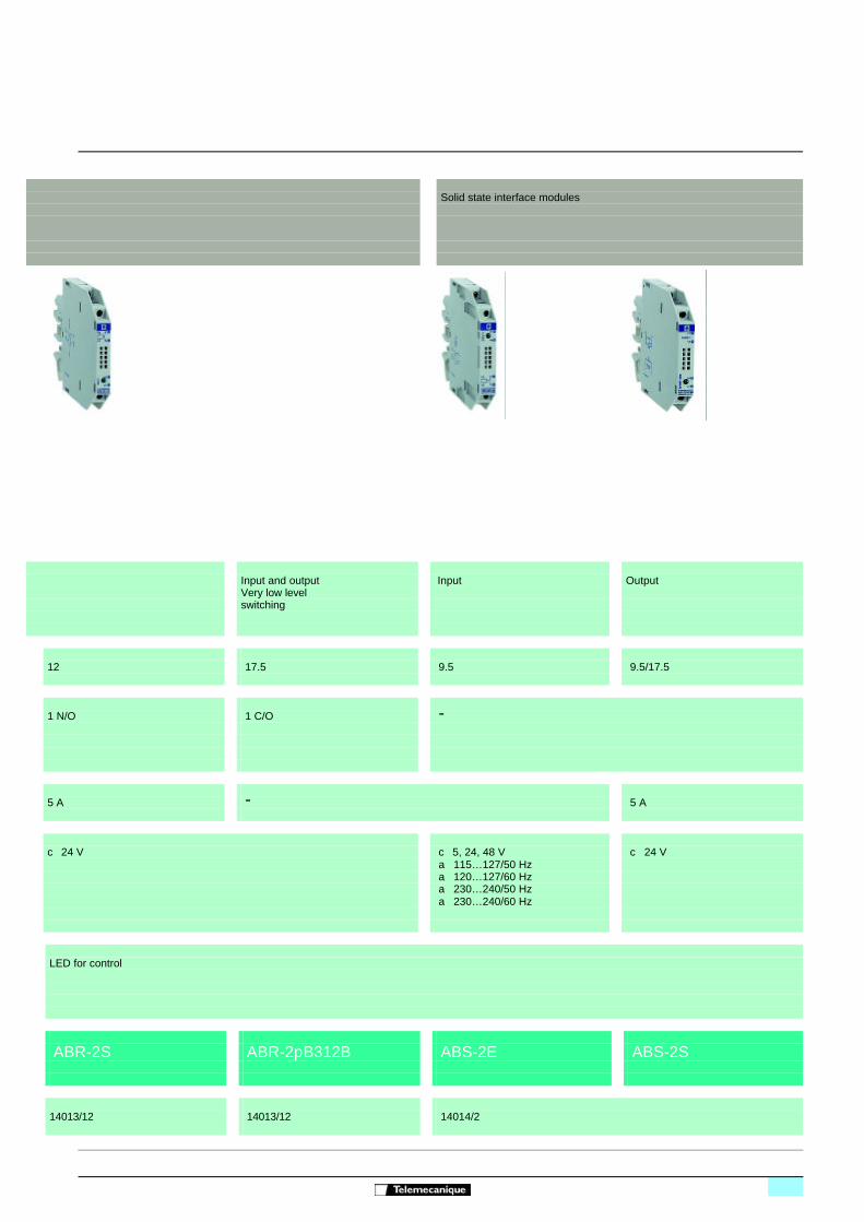
Solid state interface modules
Input and output Input OutputVery low level switching
12 17.5 9.5 9.5/17.5
1 N/O 1 C/O -
5 A - 5 A
c 24 V c 5, 24, 48 V c 24 Va 115…127/50 Hza 120…127/60 Hza 230…240/50 Hza 230…240/60 Hz
LED for control
ABR-2S ABR-2pB312B ABS-2E ABS-2S
14013/12 14013/12 14014/2
4001_Ver4.00-EN.fm/2
Presentation
pages 14001/3 to 14001/5 pages 14001/6 to 14001/11
InterfacesFor discrete signalsElectromechanical interface modules
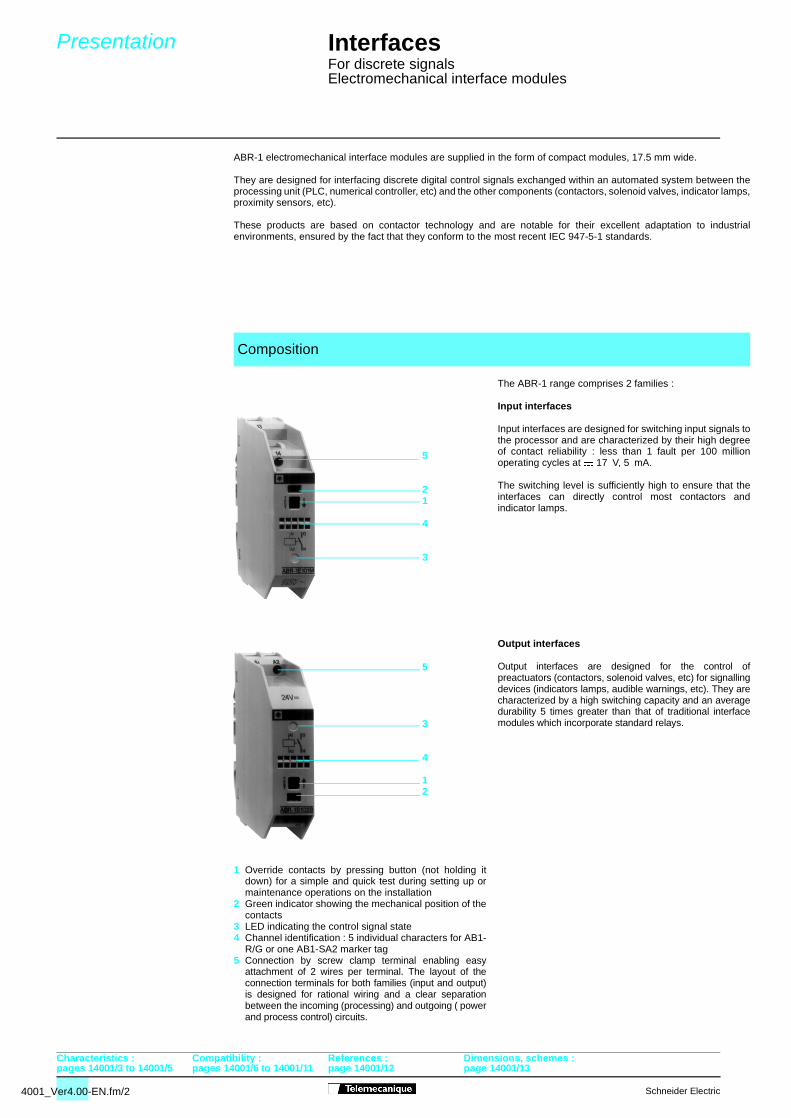
ABR-1 electromechanical interface modules are supplied in the form of compact modules, 17.5 mm wide.
They are designed for interfacing discrete digital control signals exchanged within an automated system between theprocessing unit (PLC, numerical controller, etc) and the other components (contactors, solenoid valves, indicator lamps,proximity sensors, etc).
These products are based on contactor technology and are notable for their excellent adaptation to industrialenvironments, ensured by the fact that they conform to the most recent IEC 947-5-1 standards.
The ABR-1 range comprises 2 families :
Input interfaces
Input interfaces are designed for switching input signals tothe processor and are characterized by their high degreeof contact reliability : less than 1 fault per 100 millionoperating cycles at $ 17 V, 5 mA.
The switching level is sufficiently high to ensure that theinterfaces can directly control most contactors andindicator lamps.
Output interfaces
Output interfaces are designed for the control ofpreactuators (contactors, solenoid valves, etc) for signallingdevices (indicators lamps, audible warnings, etc). They arecharacterized by a high switching capacity and an averagedurability 5 times greater than that of traditional interfacemodules which incorporate standard relays.
1 Override contacts by pressing button (not holding itdown) for a simple and quick test during setting up ormaintenance operations on the installation
2 Green indicator showing the mechanical position of thecontacts
3 LED indicating the control signal state4 Channel identification : 5 individual characters for AB1-
R/G or one AB1-SA2 marker tag5 Connection by screw clamp terminal enabling easy
attachment of 2 wires per terminal. The layout of theconnection terminals for both families (input and output)is designed for rational wiring and a clear separationbetween the incoming (processing) and outgoing ( powerand process control) circuits.
Composition
Characteristics : Compatibility : References : Dimensions, schemes :
5
3
4
12
5
21
4
3
Schneider Electric
page 14001/12 page 14001/13
Schneider Electric
Presentation
pages 14001/2 pages 14001/6 to 14001/11
InterfacesFor discrete signalsElectromechanical interface modules
–/
+/
–
+
A2
A1
–/
+/
–
+
24...125 V ...240 V
A1
A2
(1) (1)
A1
A2
A1
A2
A2
A1
A2
A1
A2
A1
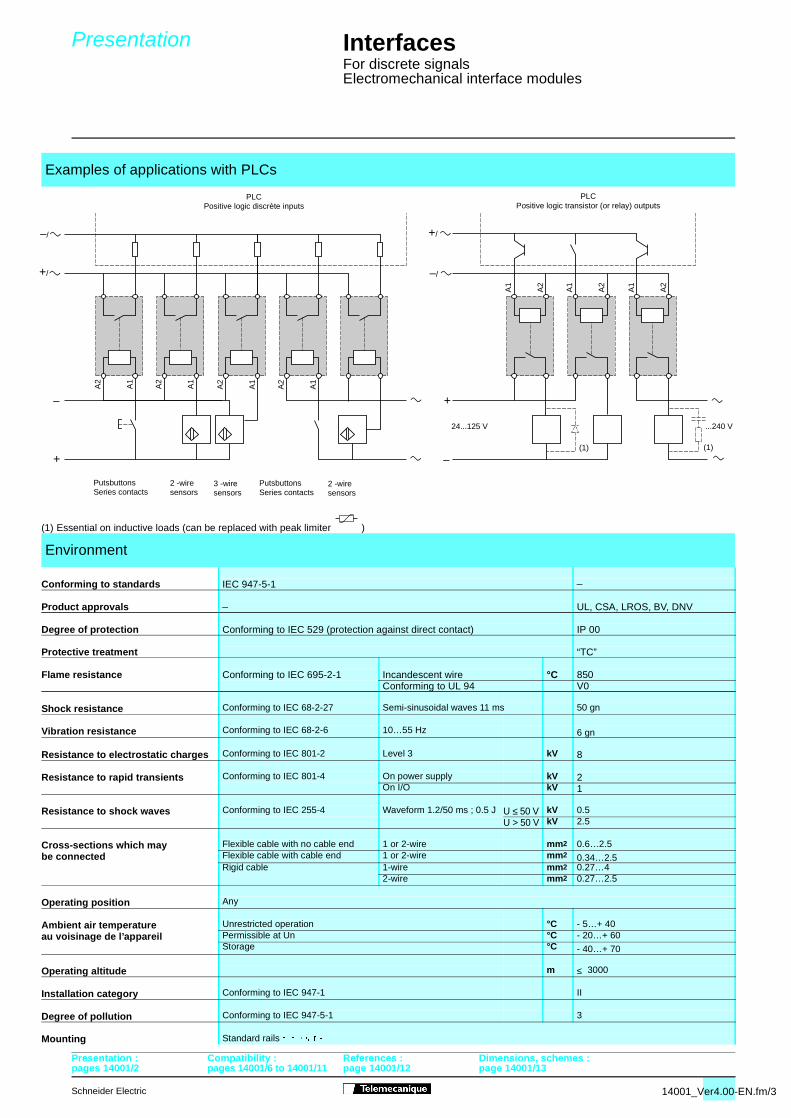
(1) Essential on inductive loads (can be replaced with peak limiter )
Examples of applications with PLCs
Environment
Conforming to standards IEC 947-5-1 _
Product approvals _ UL, CSA, LROS, BV, DNV
Degree of protection Conforming to IEC 529 (protection against direct contact) IP 00
Protective treatment “TC”
Flame resistance Conforming to IEC 695-2-1 Incandescent wire °C 850Conforming to UL 94 V0
Shock resistance Conforming to IEC 68-2-27 Semi-sinusoidal waves 11 ms 50 gn
Vibration resistance Conforming to IEC 68-2-6 10…55 Hz 6 gn
Resistance to electrostatic charges Conforming to IEC 801-2 Level 3 kV 8
Resistance to rapid transients Conforming to IEC 801-4 On power supply kV 2On I/O kV 1
Resistance to shock waves Conforming to IEC 255-4 Waveform 1.2/50 ms ; 0.5 J U ≤ 50 V kV 0.5U > 50 V kV 2.5
Cross-sections which may Flexible cable with no cable end 1 or 2-wire mm2 0.6…2.5be connected Flexible cable with cable end 1 or 2-wire mm2 0.34…2.5
Rigid cable 1-wire mm2 0.27…42-wire mm2 0.27…2.5
Operating position Any
Ambient air temperature Unrestricted operation °C - 5…+ 40au voisinage de l’appareil Permissible at Un °C - 20…+ 60
Storage °C - 40…+ 70
Operating altitude m ≤ 3000
Installation category Conforming to IEC 947-1 II
Degree of pollution Conforming to IEC 947-5-1 3
Mounting Standard rails � � �
Presentation : Compatibility : References : Dimensions, schemes :
PLCPositive logic discrète inputs
PLCPositive logic transistor (or relay) outputs
PutsbuttonsSeries contacts
2 -wiresensors
3 -wiresensors
PutsbuttonsSeries contacts
2 -wiresensors
14001_Ver4.00-EN.fm/3
page 14001/12 page 14001/13
4001_Ver4.00-EN.fm/4
page 14001/2 pages 14001/6 to 14001/11 p
Characteristics
InterfacesFor discrete signalsElectromechanical interface modulesPresentation : Compatibility : References : Dimensions, schemes :
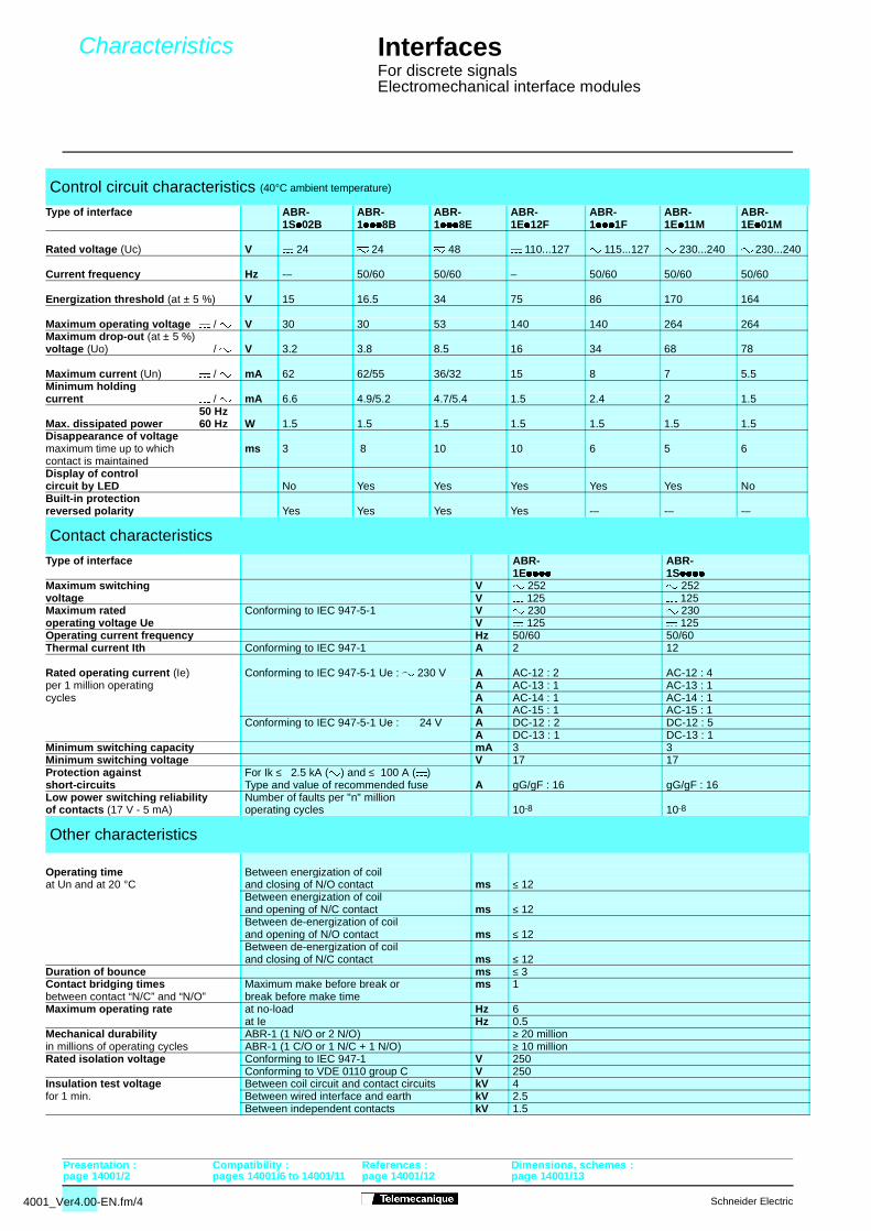
Control circuit characteristics (40°C ambient temperature)
Type of interface ABR- ABR- ABR- ABR- ABR- ABR- ABR-1S/02B 1///8B 1///8E 1E/12F 1///1F 1E/11M 1E/01M
Rated voltage (Uc) V $ 24 7 24 7 48 $ 110...127 " 115...127 " 230...240 " 230...240
Current frequency Hz -– 50/60 50/60 – 50/60 50/60 50/60
Energization threshold (at ± 5 %) V 15 16.5 34 75 86 170 164
Maximum operating voltage $ / " V 30 30 53 140 140 264 264Maximum drop-out (at ± 5 %)voltage (Uo) $ / " V 3.2 3.8 8.5 16 34 68 78
Maximum current (Un) $ / " mA 62 62/55 36/32 15 8 7 5.5Minimum holdingcurrent $ / " mA 6.6 4.9/5.2 4.7/5.4 1.5 2.4 2 1.5
50 HzMax. dissipated power 60 Hz W 1.5 1.5 1.5 1.5 1.5 1.5 1.5Disappearance of voltagemaximum time up to which ms 3 8 10 10 6 5 6contact is maintainedDisplay of controlcircuit by LED No Yes Yes Yes Yes Yes NoBuilt-in protectionreversed polarity Yes Yes Yes Yes -– -– -–
Contact characteristics
Type of interface ABR- ABR-1E//// 1S////
Maximum switching V " 252 " 252 voltage V $ 125 $ 125 Maximum rated Conforming to IEC 947-5-1 V " 230 " 230 operating voltage Ue V $ 125 $ 125 Operating current frequency Hz 50/60 50/60Thermal current Ith Conforming to IEC 947-1 A 2 12
Rated operating current (Ie) Conforming to IEC 947-5-1 Ue : " 230 V A AC-12 : 2 AC-12 : 4per 1 million operating A AC-13 : 1 AC-13 : 1cycles A AC-14 : 1 AC-14 : 1
A AC-15 : 1 AC-15 : 1Conforming to IEC 947-5-1 Ue : $ 24 V A DC-12 : 2 DC-12 : 5
A DC-13 : 1 DC-13 : 1Minimum switching capacity mA 3 3Minimum switching voltage V 17 17Protection against For Ik ≤ 2.5 kA (") and ≤ 100 A ($)short-circuits Type and value of recommended fuse A gG/gF : 16 gG/gF : 16Low power switching reliability Number of faults per "n" millionof contacts (17 V - 5 mA) operating cycles 10-8 10-8
Other characteristics
Operating time Between energization of coilat Un and at 20 °C and closing of N/O contact ms ≤ 12
Between energization of coiland opening of N/C contact ms ≤ 12Between de-energization of coiland opening of N/O contact ms ≤ 12Between de-energization of coiland closing of N/C contact ms ≤ 12
Duration of bounce ms ≤ 3Contact bridging times Maximum make before break or ms 1between contact “N/C” and “N/O” break before make timeMaximum operating rate at no-load Hz 6
at Ie Hz 0.5 Mechanical durability ABR-1 (1 N/O or 2 N/O) ≥ 20 millionin millions of operating cycles ABR-1 (1 C/O or 1 N/C + 1 N/O) ≥ 10 millionRated isolation voltage Conforming to IEC 947-1 V 250
Conforming to VDE 0110 group C V 250Insulation test voltage Between coil circuit and contact circuits kV 4for 1 min. Between wired interface and earth kV 2.5
Between independent contacts kV 1.5
Schneider Electric
age 14001/12 page 14001/13
Schneider Electric
Characteristics
page 14001/2 pages 14001/6 to 14001/1
InterfacesFor discrete signalsElectromechanical interface modules
5
4
3
2
1
1 2 3 4 5(A)
6
0
0
34
2
6
5
4
3
2
1
1 2 3 4 5(A)
6
0
0
6
3
1
4
2
2
1
0,5 1 1,5 2 2,5
(A)
3
0
0
3
1
2
3
4
5
4
3
2
1
0
1 2 3 4 5
(A)
2
3
6
60
1
2
1
0,5 1 1,5 2 2,5
(A)
3
0
0
3
3
1
2
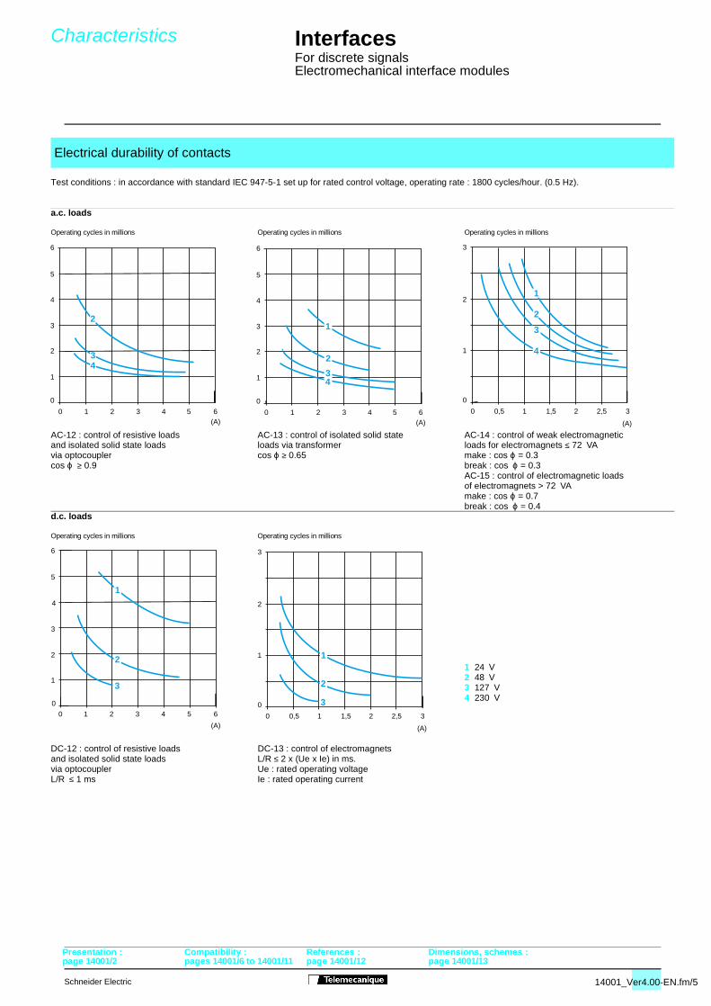
Test conditions : in accordance with standard IEC 947-5-1 set up for rated control voltage, operating rate : 1800 cycles/hour. (0.5 Hz).
a.c. loads
d.c. loads
Electrical durability of contacts
Operating cycles in millions Operating cycles in millions Operating cycles in millions
AC-12 : control of resistive loads AC-13 : control of isolated solid state AC-14 : control of weak electromagnetic and isolated solid state loads loads via transformer loads for electromagnets ≤ 72 VAvia optocoupler cos ϕ ≥ 0.65 make : cos ϕ = 0.3cos ϕ ≥ 0.9 break : cos ϕ = 0.3
AC-15 : control of electromagnetic loadsof electromagnets > 72 VAmake : cos ϕ = 0.7break : cos ϕ = 0.4
Operating cycles in millions Operating cycles in millions
1 24 V2 48 V3 127 V4 230 V
DC-12 : control of resistive loads DC-13 : control of electromagnetsand isolated solid state loads L/R ≤ 2 x (Ue x Ie) in ms.via optocoupler Ue : rated operating voltageL/R ≤ 1 ms Ie : rated operating current
Presentation : Compatibility : References : Dimensions, schemes :
14001_Ver4.00-EN.fm/5
1 page 14001/12 page 14001/13
4001_Ver4.00-EN.fm/6
Compatibility with PLC outputs
page 14001/2 pages 14001/3 to 14001/5 p
InterfacesFor discrete signalsElectromechanical interface modules
Solid state outputs
Relay outputs
Solid state outputs
Relay outputs
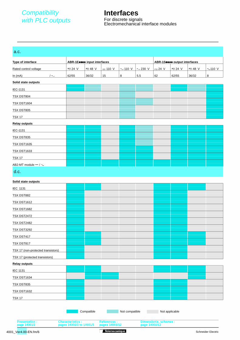
a.c.
Type of interface ABR-1E//// input interfaces ABR-1S//// output interfaces
Rated control voltage 7 24 V 7 48 V $ 110 V " 110 V " 230 V $ 24 V 7 24 V 7 48 V "110 V
In (mA) $ / " 62/55 36/32 15 8 5.5 62 62/55 36/32 8
IEC-1131
TSX DST804
TSX DST1604
TSX DST805
TSX 17
IEC-1131
TSX DST835
TSX DST1635
TSX DST1633
TSX 17
AB2-MT module $ / "
d.c.
IEC 1131
TSX DST882
TSX DST1612
TSX DST1682
TSX DST2472
TSX DST2482
TSX DST3292
TSX DST417
TSX DST817
TSX 17 (non-protected transistors)
TSX 17 (protected transistors)
IEC 1131
TSX DST1634
TSX DST835
TSX DST1632
TSX 17
Compatible Not compatible Not applicable
Presentation : Characteristics : References : Dimensionis, schemes :
Schneider Electric
ages 14001/12 page 14001/13
Schneider Electric
Compatibility with contactors and solenoid actuators
page 14001/2 pages 14001/3 to 14001
InterfacesFor discrete signalsElectromechanical interface modules
Contactors
Solenoid actuators
Contactors
Solenoid actuator
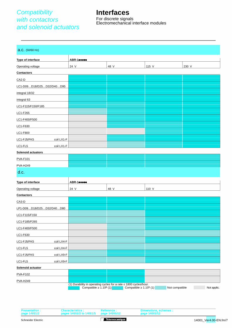
(1) Durability in operating cycles for a rate ≤ 1800 cycles/hour.
a.c. (50/60 Hz)
Type of interface ABR-1/////
Operating voltage 24 V 48 V 115 V 230 V
CA2-D
LC1-D09…D18/D25…D32/D40…D95
integral 18/32
integral 63
LC1-F115/F150/F185
LC1-F265
LC1-F400/F500
LC1-F630
LC1-F800
LC1-FJ5/FK5 coil LX1-F
LC1-FL5 coil LX1-F
PVA-F101
PVA-H249
d.c.
Type of interface ABR-1/////
Operating voltage 24 V 48 V 110 V
CA3-D
LP1-D09…D18/D25…D32/D40…D80
LC1-F115/F150
LC1-F185/F265
LC1-F400/F500
LC1-F630
LC1-FJ5/FK5 coil LX4-F
LC1-FL5 coil LX4-F
LC1-FJ5/FK5 coil LX9-F
LC1-FL5 coil LX9-F
PVA-F102
PVA-H249
Compatible ≥ 1.106 (1) Compatible ≥ 1.105 (1) Not compatible Not applic.
Presentation : Characteristics : Reference : Dimensions, schemes :
14001_Ver4.00-EN.fm/7
/5 page 14001/12 page 14001/13
4001_Ver4.00-EN.fm/8
Compatibility with Telemecanique inductive and capacitive sensors
page 14001/2 pages 14001/3 to 14001/5 p
InterfacesFor discrete signalsElectromechanical interface modules
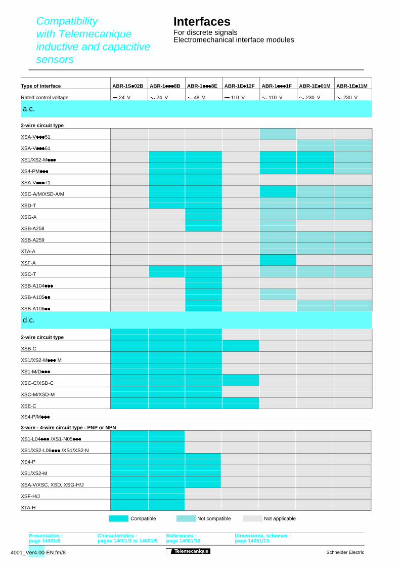
2-wire circuit type
XS4-P/M///
3-wire - 4-wire circuit type : PNP or NPN
Type of interface ABR-1S/02B ABR-1///8B ABR-1///8E ABR-1E/12F ABR-1///1F ABR-1E/01M ABR-1E/11M
Rated control voltage $ 24 V 7 24 V 7 48 V $ 110 V " 110 V " 230 V " 230 V
a.c.
XSA-V///51
XSA-V///61
XS1/XS2-M///
XS4-PM///
XSA-V///71
XSC-A/M/XSD-A/M
XSD-T
XSG-A
XSB-A258
XSB-A259
XTA-A
XSF-A
XSC-T
XSB-A104///
XSB-A105//
XSB-A106//
d.c.
2-wire circuit type
XSB-C
XS1/XS2-M/// M
XS1-M/D///
XSC-C/XSD-C
XSC-M/XSD-M
XSE-C
XS1-L04/// /XS1-N05///
XS1/XS2-L06/// /XS1/XS2-N
XS4-P
XS1/XS2-M
XSA-V/XSC, XSD, XSG-H/J
XSF-H/J
XTA-H
Compatible Not compatible Not applicable
Presentation : Characteristics : References : Dimensions, schemes :
Schneider Electric
age 14001/12 page 14001/13
Schneider Electric
page 14001/2 pages 14001/3 to 14001/
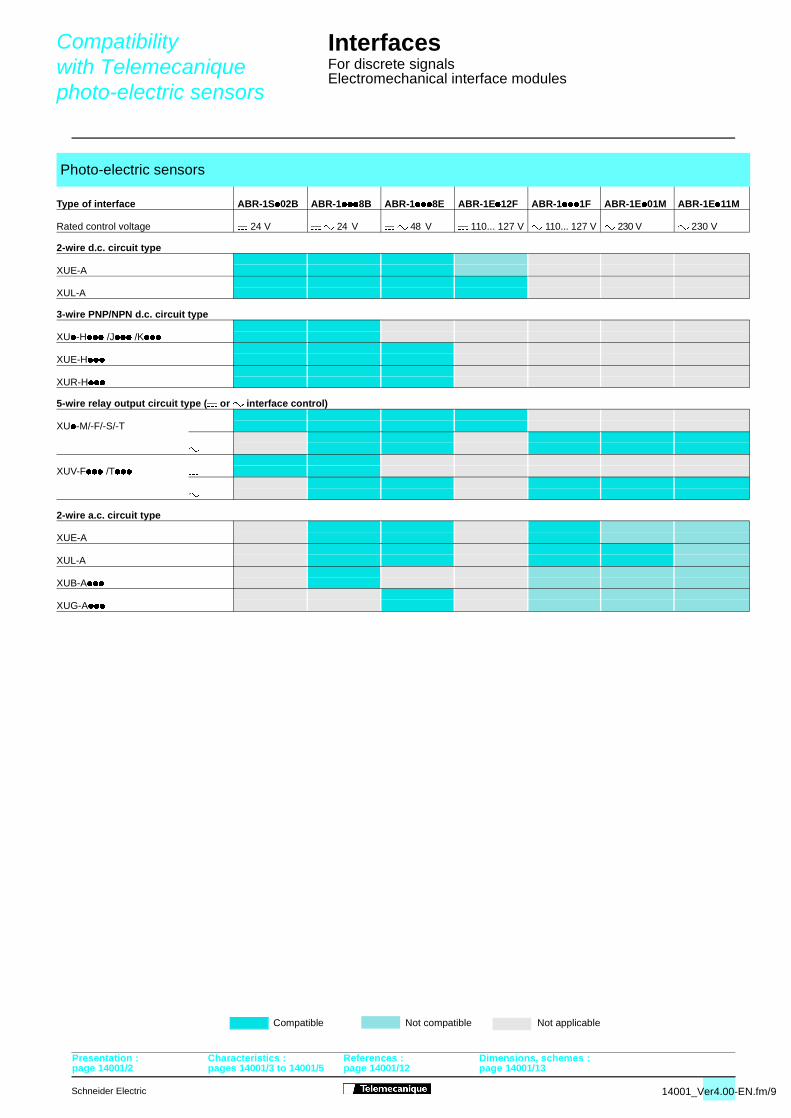
Compatibility with Telemecanique photo-electric sensors
InterfacesFor discrete signalsElectromechanical interface modules
Presentation : Characteristics : References : Dimensions, schemes :
2-wire d.c. circuit type
3-wire PNP/NPN d.c. circuit type
5-wire relay output circuit type ($ or " interface control)
2-wire a.c. circuit type
Photo-electric sensors
Type of interface ABR-1S/02B ABR-1///8B ABR-1///8E ABR-1E/12F ABR-1///1F ABR-1E/01M ABR-1E/11M
Rated control voltage $ 24 V $ " 24 V $ " 48 V $ 110... 127 V " 110... 127 V " 230 V " 230 V
XUE-A
XUL-A
XU/-H/// /J/// /K///
XUE-H///
XUR-H///
XU/-M/-F/-S/-T $
"
XUV-F/// /T/// $
"
XUE-A
XUL-A
XUB-A///
XUG-A///
Compatible Not compatible Not applicable
14001_Ver4.00-EN.fm/9
5 page 14001/12 page 14001/13
4001_Ver4.00-EN.fm/10
page 14001/2 pages 14001/3 to 14001/5 p
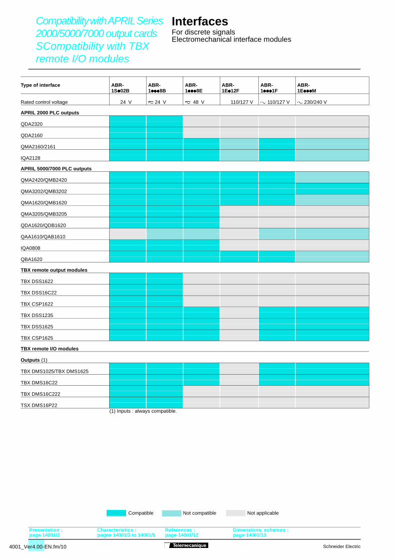
Compatibility with APRIL Series 2000/5000/7000 output cardsSCompatibility with TBX remote I/O modules
InterfacesFor discrete signalsElectromechanical interface modules
Presentation : Characteristics : References : Dimensions, schemes :
APRIL 2000 PLC outputs
APRIL 5000/7000 PLC outputs
TBX remote output modules
TBX remote I/O modules
(1) Inputs : always compatible.
Type of interface ABR- ABR- ABR- ABR- ABR- ABR-1S/02B 1///8B 1///8E 1E/12F 1///1F 1E///M
Rated control voltage $ 24 V 7 24 V 7 48 V $ 110/127 V " 110/127 V " 230/240 V
QDA2320
QDA2160
QMA2160/2161
IQA2128
QMA2420/QMB2420
QMA3202/QMB3202
QMA1620/QMB1620
QMA3205/QMB3205
QDA1620/QDB1620
QAA1610/QAB1610
IQA0808
QBA1620
TBX DSS1622
TBX DSS16C22
TBX CSP1622
TBX DSS1235
TBX DSS1625
TBX CSP1625
Outputs (1)
TBX DMS1025/TBX DMS1625
TBX DMS16C22
TBX DMS16C222
TSX DMS16P22
Compatible Not compatible Not applicable
Schneider Electric
age 14001/12 page 14001/13
Schneider Electric
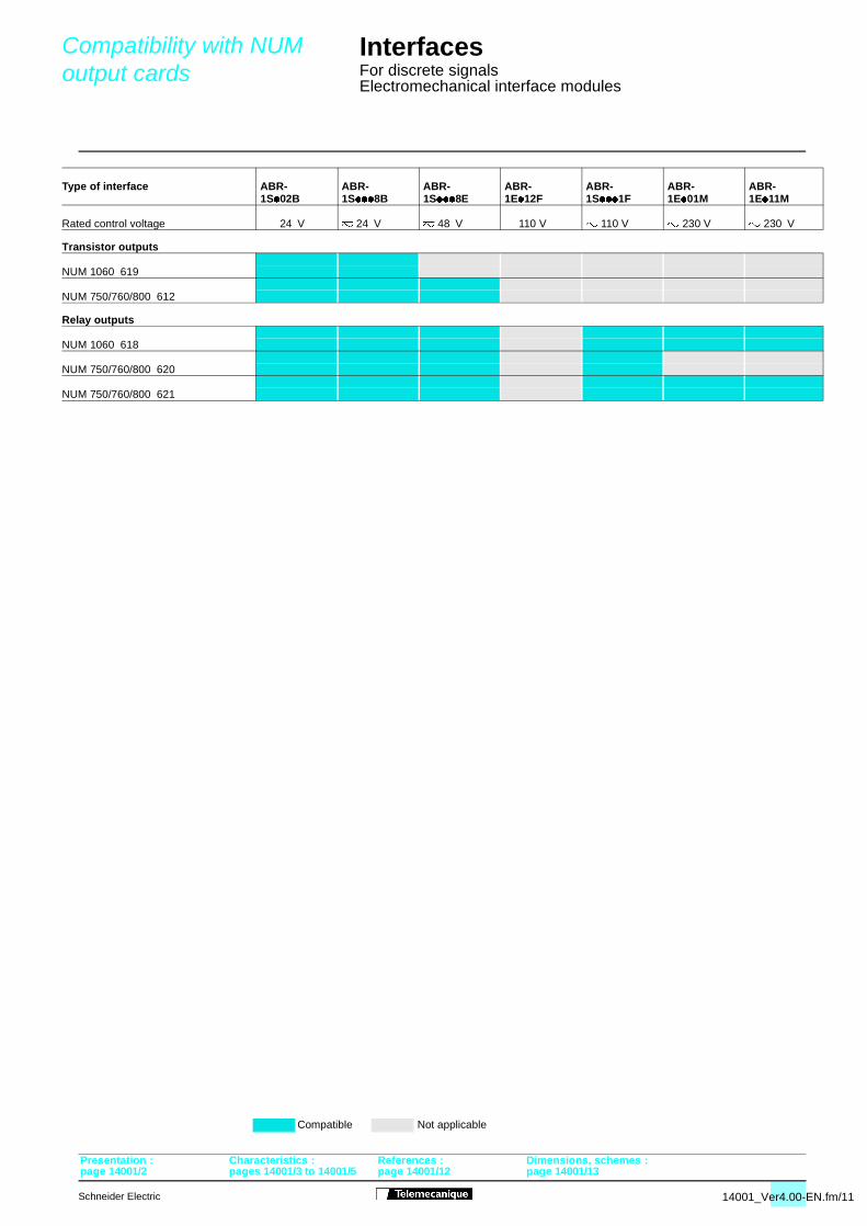
Compatibility with NUM output cards
page 14001/2 pages 14001/3 to 14001
InterfacesFor discrete signalsElectromechanical interface modules
Transistor outputs
Relay outputs
Type of interface ABR- ABR- ABR- ABR- ABR- ABR- ABR- 1S/02B 1S///8B 1S///8E 1E/12F 1S///1F 1E/01M 1E/11M
Rated control voltage $ 24 V 7 24 V 7 48 V $ 110 V " 110 V " 230 V " 230 V
NUM 1060 619
NUM 750/760/800 612
NUM 1060 618
NUM 750/760/800 620
NUM 750/760/800 621
Compatible Not applicable
Presentation : Characteristics : References : Dimensions, schemes :
14001_Ver4.00-EN.fm/11
/5 page 14001/12 page 14001/13
4001_Ver4.00-EN.fm/12
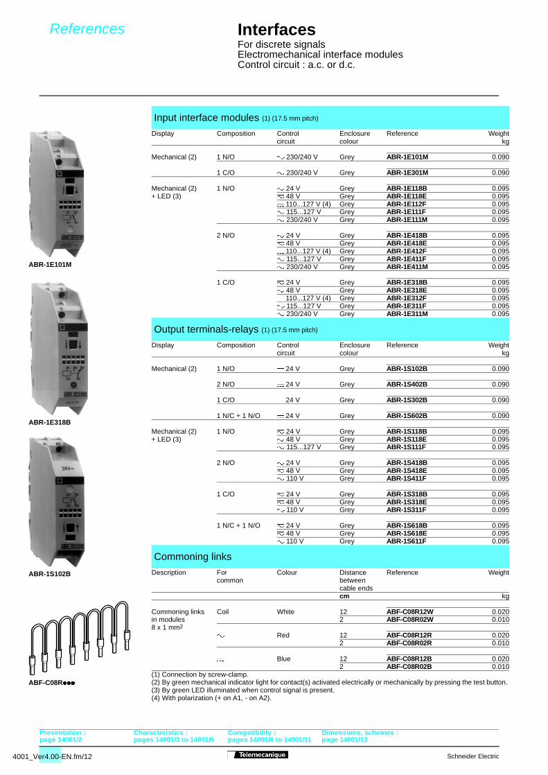
References
page 14001/2 pages 14001/3 to 14001/5 p
InterfacesFor discrete signalsElectromechanical interface modulesControl circuit : a.c. or d.c.
(1) Connection by screw-clamp.(2) By green mechanical indicator light for contact(s) activated electrically or mechanically by pressing the test button. (3) By green LED illuminated when control signal is present.(4) With polarization (+ on A1, - on A2).
Input interface modules (1) (17.5 mm pitch)
Display Composition Control Enclosure Reference Weightcircuit colour kg
Mechanical (2) 1 N/O " 230/240 V Grey ABR-1E101M 0.090
1 C/O " 230/240 V Grey ABR-1E301M 0.090
Mechanical (2) 1 N/O 7 24 V Grey ABR-1E118B 0.095+ LED (3) 7 48 V Grey ABR-1E118E 0.095
$ 110...127 V (4) Grey ABR-1E112F 0.095" 115...127 V Grey ABR-1E111F 0.095" 230/240 V Grey ABR-1E111M 0.095
2 N/O 7 24 V Grey ABR-1E418B 0.0957 48 V Grey ABR-1E418E 0.095$ 110...127 V (4) Grey ABR-1E412F 0.095" 115...127 V Grey ABR-1E411F 0.095" 230/240 V Grey ABR-1E411M 0.095
1 C/O 7 24 V Grey ABR-1E318B 0.0957 48 V Grey ABR-1E318E 0.095$ 110...127 V (4) Grey ABR-1E312F 0.095" 115...127 V Grey ABR-1E311F 0.095" 230/240 V Grey ABR-1E311M 0.095
Output terminals-relays (1) (17.5 mm pitch)
Display Composition Control Enclosure Reference Weightcircuit colour kg
Mechanical (2) 1 N/O $ 24 V Grey ABR-1S102B 0.090
2 N/O $ 24 V Grey ABR-1S402B 0.090
1 C/O $ 24 V Grey ABR-1S302B 0.090
1 N/C + 1 N/O $ 24 V Grey ABR-1S602B 0.090
Mechanical (2) 1 N/O 7 24 V Grey ABR-1S118B 0.095+ LED (3) 7 48 V Grey ABR-1S118E 0.095
" 115...127 V Grey ABR-1S111F 0.095
2 N/O 7 24 V Grey ABR-1S418B 0.0957 48 V Grey ABR-1S418E 0.095" 110 V Grey ABR-1S411F 0.095
1 C/O 7 24 V Grey ABR-1S318B 0.0957 48 V Grey ABR-1S318E 0.095" 110 V Grey ABR-1S311F 0.095
1 N/C + 1 N/O 7 24 V Grey ABR-1S618B 0.0957 48 V Grey ABR-1S618E 0.095" 110 V Grey ABR-1S611F 0.095
Commoning links
Description For Colour Distance Reference Weightcommon between
cable endscm kg
Commoning links Coil White 12 ABF-C08R12W 0.020in modules 2 ABF-C08R02W 0.0108 x 1 mm2
" Red 12 ABF-C08R12R 0.0202 ABF-C08R02R 0.010
$ Blue 12 ABF-C08R12B 0.0202 ABF-C08R02B 0.010
Presentation : Characteristics : Compatibility : Dimensions, schemes :
ABR-1E101M
ABR-1S102B
ABR-1E318B
ABF-C08R///
Schneider Electric
ages 14001/6 to 14001/11 page 14001/13
Schneider Electric
Dimensions, schemes
page 14001/2 pages 14001/3 to 14001/
InterfacesFor discrete signalsElectromechanical interface modules
A1
A2
2324
1112
A1(+)
A2
2324
1112
A1
A2
2324
1112
A1 1314
A2
A1(+)
A2
1314
A1
A2
1114 12
A1
A2
1114 12
A1
A2
1314
2324
A1(+)
A2
1114 12
A1(+)
A2
1314
2324
78
75
70,517,5
74
63
78
75
70,517,5
74
63
A1
A2
1314
A1
A2
1314
2324
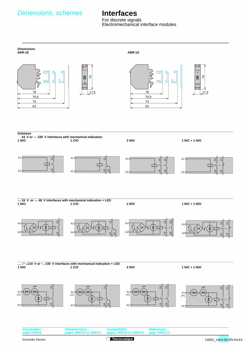
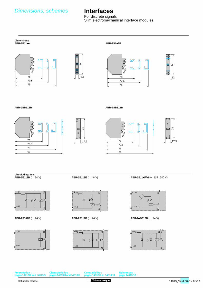
Dimensions
Schemes$ 24 V or " 230 V interfaces with mechanical indication
7 24 V or 7 48 V interfaces with mechanical indication + LED
$ / "110 V or " 230 V interfaces with mechanical indication + LED
ABR-1E ABR-1S
1 N/O 1 C/O 2 N/O 1 N/C + 1 N/O
1 N/O 1 C/O 2 N/O 1 N/C + 1 N/O
1 N/O 1 C/O 2 N/O 1 N/C + 1 N/O
Presentation : Characteristics : Compatibility : References :
14001_Ver4.00-EN.fm/13
5 pages 14001/6 to 14001/11 page 14001/12
4013_Ver4.00-EN.fm/2
pages 14013/4 and 14013/5 pages 14013/6 to 14013/11
Presentation
Interfaces For discrete signalsSlim electromechanical interface modules3
2
1
3
2
1
3
2
1
Characteristics : Compatibility : References : Dimensions :
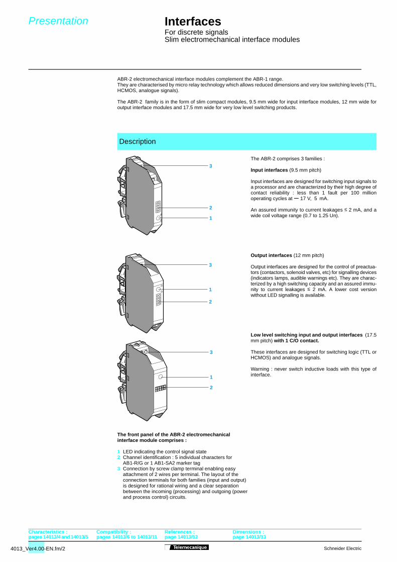
ABR-2 electromechanical interface modules complement the ABR-1 range.They are characterised by micro relay technology which allows reduced dimensions and very low switching levels (TTL,HCMOS, analogue signals).
The ABR-2 family is in the form of slim compact modules, 9.5 mm wide for input interface modules, 12 mm wide foroutput interface modules and 17.5 mm wide for very low level switching products.
The ABR-2 comprises 3 families :
Input interfaces (9.5 mm pitch)
Input interfaces are designed for switching input signals toa processor and are characterized by their high degree ofcontact reliability : less than 1 fault per 100 millionoperating cycles at $ 17 V, 5 mA.
An assured immunity to current leakages ≤ 2 mA, and awide coil voltage range (0.7 to 1.25 Un).
Output interfaces (12 mm pitch)
Output interfaces are designed for the control of preactua-tors (contactors, solenoid valves, etc) for signalling devices(indicators lamps, audible warnings etc). They are charac-terized by a high switching capacity and an assured immu-nity to current leakages ≤ 2 mA. A lower cost versionwithout LED signalling is available.
Low level switching input and output interfaces (17.5mm pitch) with 1 C/O contact.
These interfaces are designed for switching logic (TTL orHCMOS) and analogue signals.
Warning : never switch inductive loads with this type ofinterface.
The front panel of the ABR-2 electromechanicalinterface module comprises :
1 LED indicating the control signal state2 Channel identification : 5 individual characters for
AB1-R/G or 1 AB1-SA2 marker tag3 Connection by screw clamp terminal enabling easy
attachment of 2 wires per terminal. The layout of theconnection terminals for both families (input and output)is designed for rational wiring and a clear separationbetween the incoming (processing) and outgoing (powerand process control) circuits.
Description
Schneider Electric
page 14013/12 page 14013/13
Schneider Electric
Installation precautions
pages 14013/4 and 14013/5 pages 14013/6 to 14013/11
InterfacesFor discrete signalsSlim electromechanical interface modules
–/
+/ –
+
–
+
A1
A2
(1) (1)+/
C1
13 14 13 14 13 14 A1
A2
A1
A2
A1
A2
A1
A2
A1
A2
13 14 13 14 13 14
A1
A2
12 14
C2
OV
11
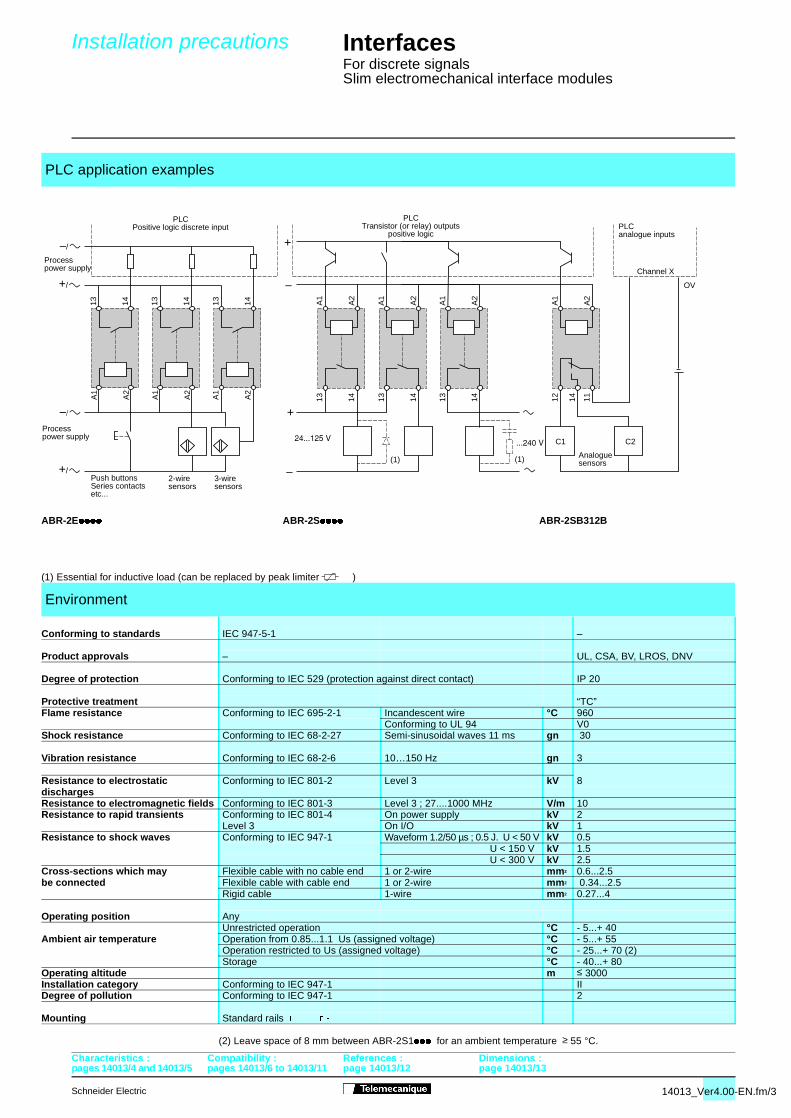
PLC application examples
ABR-2E//// ABR-2S//// ABR-2SB312B
(1) Essential for inductive load (can be replaced by peak limiter )
Environment
Conforming to standards IEC 947-5-1 –
Product approvals – UL, CSA, BV, LROS, DNV
Degree of protection Conforming to IEC 529 (protection against direct contact) IP 20
Protective treatment “TC”Flame resistance Conforming to IEC 695-2-1 Incandescent wire °C 960
Conforming to UL 94 V0Shock resistance Conforming to IEC 68-2-27 Semi-sinusoidal waves 11 ms gn 30
Vibration resistance Conforming to IEC 68-2-6 10…150 Hz gn 3
Resistance to electrostatic Conforming to IEC 801-2 Level 3 kV 8 dischargesResistance to electromagnetic fields Conforming to IEC 801-3 Level 3 ; 27....1000 MHz V/m 10Resistance to rapid transients Conforming to IEC 801-4 On power supply kV 2
Level 3 On I/O kV 1Resistance to shock waves Conforming to IEC 947-1 Waveform 1.2/50 µs ; 0.5 J. U < 50 V kV 0.5
U < 150 V kV 1.5 U < 300 V kV 2.5
Cross-sections which may Flexible cable with no cable end 1 or 2-wire mm2 0.6...2.5be connected Flexible cable with cable end 1 or 2-wire mm2 0.34...2.5
Rigid cable 1-wire mm2 0.27...4
Operating position AnyUnrestricted operation °C - 5...+ 40
Ambient air temperature Operation from 0.85...1.1 Us (assigned voltage) °C - 5...+ 55Operation restricted to Us (assigned voltage) °C - 25...+ 70 (2)Storage °C - 40...+ 80
Operating altitude m ≤ 3000Installation category Conforming to IEC 947-1 IIDegree of pollution Conforming to IEC 947-1 2
Mounting Standard rails � � �
(2) Leave space of 8 mm between ABR-2S1/// for an ambient temperature ≥ 55 °C.
Characteristics : Compatibility : References : Dimensions :
PLCanalogue inputs
PLCTransistor (or relay) outputs
positive logic
PLCPositive logic discrete input
Processpower supply
Processpower supply
Push buttonsSeries contactsetc...
2-wiresensors
3-wiresensors
Analoguesensors
Channel X
14013_Ver4.00-EN.fm/3
page 14013/12 page 14013/13
4013_Ver4.00-EN.fm/4
pages 14013/2 and 14013/3 pages 14013/6 to 14013/11 p
Characteristics
Interfaces For discrete signalsSlim electromechanical interface modulesPresentation : Compatibility : References : Dimensions :
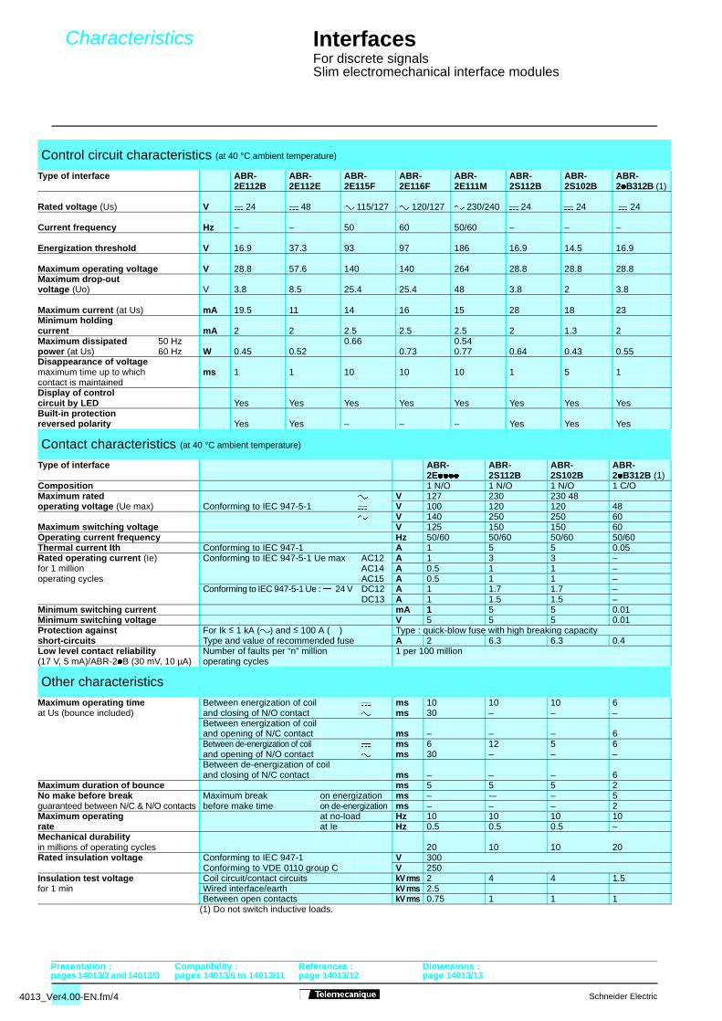
Control circuit characteristics (at 40 °C ambient temperature)
Type of interface ABR- ABR- ABR- ABR- ABR- ABR- ABR- ABR-2E112B 2E112E 2E115F 2E116F 2E111M 2S112B 2S102B 2/B312B (1)
Rated voltage (Us) V $ 24 $ 48 " 115/127 " 120/127 " 230/240 $ 24 $ 24 $ 24
Current frequency Hz – – 50 60 50/60 – – –
Energization threshold V 16.9 37.3 93 97 186 16.9 14.5 16.9
Maximum operating voltage V 28.8 57.6 140 140 264 28.8 28.8 28.8Maximum drop-out voltage (Uo) V 3.8 8.5 25.4 25.4 48 3.8 2 3.8
Maximum current (at Us) mA 19.5 11 14 16 15 28 18 23Minimum holding current mA 2 2 2.5 2.5 2.5 2 1.3 2Maximum dissipated 50 Hz 0.66 0.54power (at Us) 60 Hz W 0.45 0.52 0.73 0.77 0.64 0.43 0.55Disappearance of voltagemaximum time up to which ms 1 1 10 10 10 1 5 1contact is maintainedDisplay of controlcircuit by LED Yes Yes Yes Yes Yes Yes Yes YesBuilt-in protectionreversed polarity Yes Yes – – – Yes Yes Yes
Contact characteristics (at 40 °C ambient temperature)
Type of interface ABR- ABR- ABR- ABR-2E//// 2S112B 2S102B 2/B312B (1)
Composition 1 N/O 1 N/O 1 N/O 1 C/OMaximum rated " V 127 230 230 48 operating voltage (Ue max) Conforming to IEC 947-5-1 $ V 100 120 120 48
" V 140 250 250 60Maximum switching voltage $ V 125 150 150 60Operating current frequency Hz 50/60 50/60 50/60 50/60Thermal current Ith Conforming to IEC 947-1 A 1 5 5 0.05Rated operating current (Ie) Conforming to IEC 947-5-1 Ue max AC12 A 1 3 3 –for 1 million AC14 A 0.5 1 1 –operating cycles AC15 A 0.5 1 1 –
Conforming to IEC 947-5-1 Ue : $ 24 V DC12 A 1 1.7 1.7 –DC13 A 1 1.5 1.5 –
Minimum switching current mA 1 5 5 0.01Minimum switching voltage V 5 5 5 0.01Protection against For Ik ≤ 1 kA (") and ≤ 100 A ($) Type : quick-blow fuse with high breaking capacityshort-circuits Type and value of recommended fuse A 2 6.3 6.3 0.4 Low level contact reliability Number of faults per “n” million 1 per 100 million(17 V, 5 mA)/ABR-2/B (30 mV, 10 µA) operating cycles
Other characteristics
Maximum operating time Between energization of coil $ ms 10 10 10 6at Us (bounce included) and closing of N/O contact " ms 30 – – –
Between energization of coiland opening of N/C contact ms – – – 6Between de-energization of coil $ ms 6 12 5 6and opening of N/O contact " ms 30 – – –Between de-energization of coiland closing of N/C contact ms – – – 6
Maximum duration of bounce ms 5 5 5 2No make before break Maximum break on energization ms – -– – 5guaranteed between N/C & N/O contacts before make time on de-energization ms – – – 2Maximum operating at no-load Hz 10 10 10 10rate at Ie Hz 0.5 0.5 0.5 –Mechanical durability in millions of operating cycles 20 10 10 20Rated insulation voltage Conforming to IEC 947-1 V 300
Conforming to VDE 0110 group C V 250Insulation test voltage Coil circuit/contact circuits kV rms 2 4 4 1.5for 1 min Wired interface/earth kV rms 2.5
Between open contacts kV rms 0.75 1 1 1(1) Do not switch inductive loads.
Schneider Electric
age 14013/12 page 14013/13
Schneider Electric
Curves
pages 14013/2 and 14013/3 pages 14013/6 to 14013/11
Interfaces For discrete signalsSlim electromechanical interface modules
5
4
3
2
1
1 2 3 4 5(A)
6
0
0
3
4
2
6
1
2
1
0,5 1 1,5 2 2,5(A)
3
0
0
3
2
43
1
2
1
0
0,5 1 1,5 2 2,5
(A)
23
3
30
1
2
1
0,5 1 1,5 2 2,5
(A)
3
0
0
3
1
23
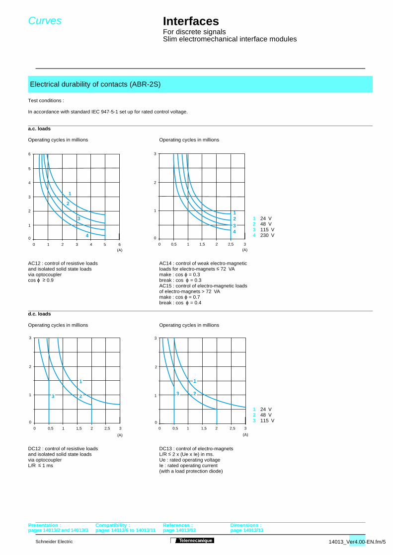
Test conditions :
In accordance with standard IEC 947-5-1 set up for rated control voltage.
a.c. loads
1 24 V2 48 V3 115 V4 230 V
d.c. loads
1 24 V2 48 V3 115 V
Electrical durability of contacts (ABR-2S)
Operating cycles in millions Operating cycles in millions
AC12 : control of resistive loads AC14 : control of weak electro-magnetic and isolated solid state loads loads for electro-magnets ≤ 72 VAvia optocoupler make : cos ϕ = 0.3cos ϕ ≥ 0.9 break : cos ϕ = 0.3
AC15 : control of electro-magnetic loadsof electro-magnets > 72 VAmake : cos ϕ = 0.7break : cos ϕ = 0.4
Operating cycles in millions Operating cycles in millions
DC12 : control of resistive loads DC13 : control of electro-magnetsand isolated solid state loads L/R ≤ 2 x (Ue x Ie) in ms.via optocoupler Ue : rated operating voltageL/R ≤ 1 ms Ie : rated operating current
(with a load protection diode)
Presentation : Compatibility : References : Dimensions :
14013_Ver4.00-EN.fm/5
page 14013/12 page 14013/13
4013_Ver4.00-EN.fm/6
pages 14013/2 and 14013/3 pages 14013/4 and 14013/5 p
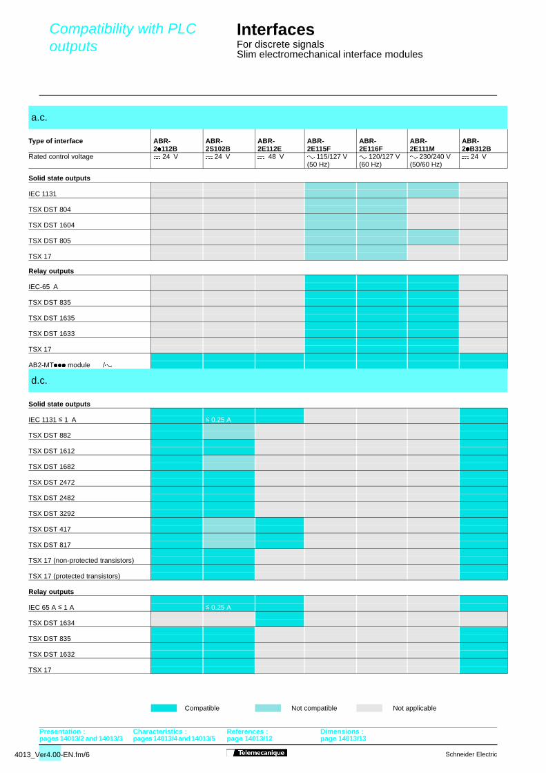
Compatibility with PLC outputs
Interfaces For discrete signalsSlim electromechanical interface modules
Presentation : Characteristics : References : Dimensions :
Solid state outputs
Relay outputs
a.c.
Type of interface ABR- ABR- ABR- ABR- ABR- ABR- ABR-2/112B 2S102B 2E112E 2E115F 2E116F 2E111M 2/B312B
Rated control voltage $ 24 V $ 24 V $ 48 V " 115/127 V " 120/127 V " 230/240 V $ 24 V(50 Hz) (60 Hz) (50/60 Hz)
IEC 1131
TSX DST 804
TSX DST 1604
TSX DST 805
TSX 17
IEC-65 A
TSX DST 835
TSX DST 1635
TSX DST 1633
TSX 17
AB2-MT/// module $ /"
d.c.
Solid state outputs
IEC 1131 ≤ 1 A ≤ 0.25 A
TSX DST 882
TSX DST 1612
TSX DST 1682
TSX DST 2472
TSX DST 2482
TSX DST 3292
TSX DST 417
TSX DST 817
TSX 17 (non-protected transistors)
TSX 17 (protected transistors)
Relay outputs
IEC 65 A ≤ 1 A ≤ 0.25 A
TSX DST 1634
TSX DST 835
TSX DST 1632
TSX 17
Compatible Not compatible Not applicable
Schneider Electric
age 14013/12 page 14013/13
Schneider Electric
pages 14013/2 and 14013/3 pages 14013/4 and 14013/5
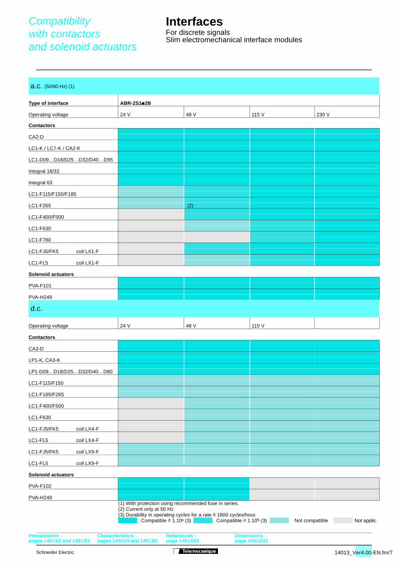
Compatibility with contactorsand solenoid actuators
Interfaces For discrete signalsSlim electromechanical interface modules
Presentation : Characteristics : References : Dimensions :
Contactors
Solenoid actuators
Contactors
Solenoid actuators
(1) With protection using recommended fuse in series.(2) Current only at 50 Hz(3) Durability in operating cycles for a rate ≤ 1800 cycles/hour.
a.c. (50/60 Hz) (1)
Type of interface ABR-2S1/2B
Operating voltage 24 V 48 V 115 V 230 V
CA2-D
LC1-K / LC7-K / CA2-K
LC1-D09…D18/D25…D32/D40…D95
Integral 18/32
Integral 63
LC1-F115/F150/F185
LC1-F265 (2)
LC1-F400/F500
LC1-F630
LC1-F780
LC1-FJ5/FK5 coil LX1-F
LC1-FL5 coil LX1-F
PVA-F101
PVA-H249
d.c.
Operating voltage 24 V 48 V 110 V
CA3-D
LP1-K, CA3-K
LP1-D09…D18/D25…D32/D40…D80
LC1-F115/F150
LC1-F185/F265
LC1-F400/F500
LC1-F630
LC1-FJ5/FK5 coil LX4-F
LC1-FL5 coil LX4-F
LC1-FJ5/FK5 coil LX9-F
LC1-FL5 coil LX9-F
PVA-F102
PVA-H249
Compatible ≥ 1.106 (3) Compatible ≥ 1.105 (3) Not compatible Not applic.
14013_Ver4.00-EN.fm/7
page 14013/12 page 14013/13
4013_Ver4.00-EN.fm/8
pages 14013/2 and 14013/3 pages 14013/4 and 14013/5 p
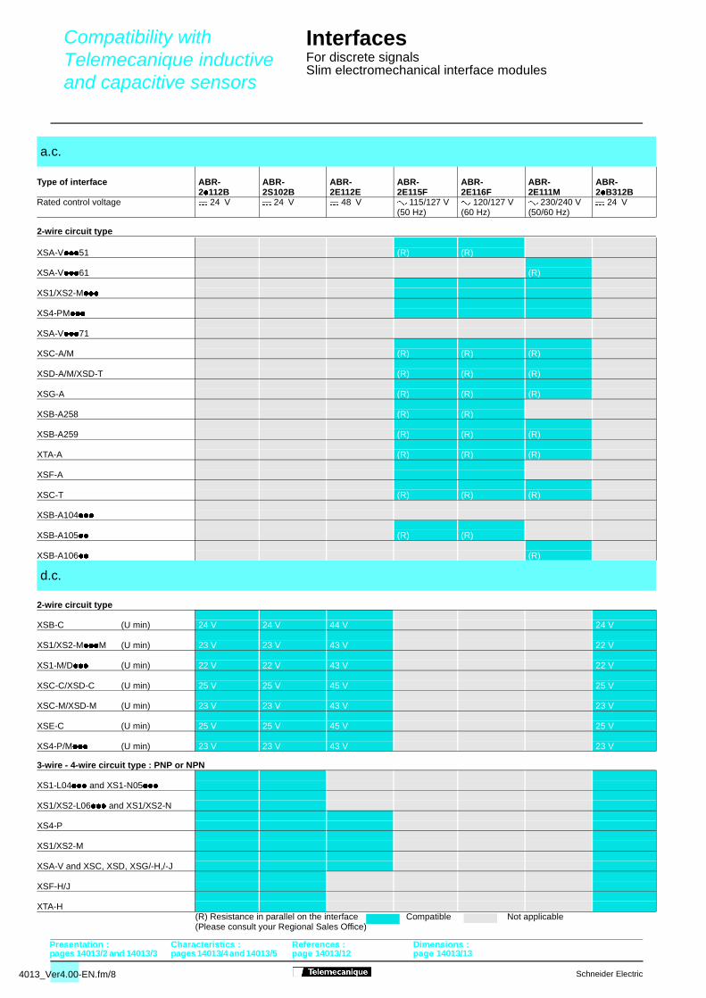
Compatibility with Telemecanique inductive and capacitive sensors
Interfaces For discrete signalsSlim electromechanical interface modules
Presentation : Characteristics : References : Dimensions :
2-wire circuit type
2-wire circuit type
3-wire - 4-wire circuit type : PNP or NPN
(Please consult your Regional Sales Office)
a.c.
Type of interface ABR- ABR- ABR- ABR- ABR- ABR- ABR-2/112B 2S102B 2E112E 2E115F 2E116F 2E111M 2/B312B
Rated control voltage $ 24 V $ 24 V $ 48 V " 115/127 V " 120/127 V " 230/240 V $ 24 V(50 Hz) (60 Hz) (50/60 Hz)
XSA-V///51 (R) (R)
XSA-V///61 (R)
XS1/XS2-M///
XS4-PM///
XSA-V///71
XSC-A/M (R) (R) (R)
XSD-A/M/XSD-T (R) (R) (R)
XSG-A (R) (R) (R)
XSB-A258 (R) (R)
XSB-A259 (R) (R) (R)
XTA-A (R) (R) (R)
XSF-A
XSC-T (R) (R) (R)
XSB-A104///
XSB-A105// (R) (R)
XSB-A106// (R)
d.c.
XSB-C (U min) 24 V 24 V 44 V 24 V
XS1/XS2-M///M (U min) 23 V 23 V 43 V 22 V
XS1-M/D/// (U min) 22 V 22 V 43 V 22 V
XSC-C/XSD-C (U min) 25 V 25 V 45 V 25 V
XSC-M/XSD-M (U min) 23 V 23 V 43 V 23 V
XSE-C (U min) 25 V 25 V 45 V 25 V
XS4-P/M/// (U min) 23 V 23 V 43 V 23 V
XS1-L04/// and XS1-N05///
XS1/XS2-L06/// and XS1/XS2-N
XS4-P
XS1/XS2-M
XSA-V and XSC, XSD, XSG/-H,/-J
XSF-H/J
XTA-H(R) Resistance in parallel on the interface Compatible Not applicable
Schneider Electric
age 14013/12 page 14013/13
Schneider Electric
pages 14013/2 and 14013/3 pages 14013/4 and 14013
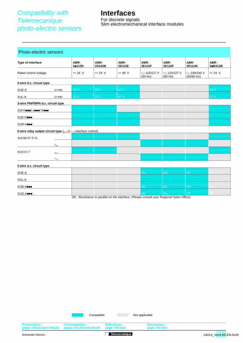
Compatibility with Telemecanique photo-electric sensors
Interfaces For discrete signalsSlim electromechanical interface modules
Presentation : Characteristics : References : Dimensions :
2-wire d.c. circuit type
3-wire PNP/NPN d.c. circuit type
5-wire relay output circuit type ($ or " interface control)
2-wire a.c. circuit type
(R) : Resistance in parallel on the interface. (Please consult your Regional Sales Office).
Photo-electric sensors
Type of interface ABR- ABR- ABR- ABR- ABR- ABR- ABR-2/112B 2S102B 2E112E 2E115F 2E116F 2E111M 2/B312B
Rated control voltage $ 24 V $ 24 V $ 48 V " 115/127 V " 120/127 V " 230/240 V $ 24 V(50 Hz) (60 Hz) (50/60 Hz)
XUE-A U min 23 V 23 V 43 V 23 V
XUL-A U min 23 V 23 V 47 V 23 V
XUl-H////-J////-K///
XUE-H///
XUR-H///
XUl-M/-F/-T/-S $
"
XUV-F/-T $
"
XUE-A (R) (R) (R) (R)
XUL-A
XUB-A/// (R) (R) (R) (R)
XUG-A/// (R) (R) (R) (R)
Compatible Not applicable
14013_Ver4.00-EN.fm/9
/5 page 14013/12 page 14013/13
4013_Ver4.00-EN.fm/10
pages 14013/2 and 14013/3 pages 14013/4 and 14013/5 p
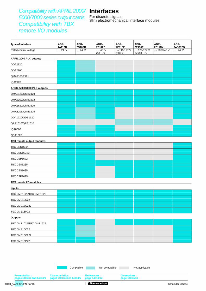
Compatibility with APRIL 2000/5000/7000 series output cards Compatibility with TBX remote I/O modules
Interfaces For discrete signalsSlim electromechanical interface modules
Presentation : Characteristics : References : Dimensions :
APRIL 2000 PLC outputs
APRIL 5000/7000 PLC outputs
Inputs
Type of interface ABR- ABR- ABR- ABR- ABR- ABR- ABR-2/112B 2S102B 2E112E 2E115F 2E116F 2E111M 2/B312B
Rated control voltage $ 24 V $ 24 V $ 48 V " 115/127 V " 120/127 V " 230/240 V $ 24 V(50 Hz) (60 Hz) (50/60 Hz)
QDA2320
QDA2160
QMA2160/2161
IQA2128
QMA2420/QMB2420
QMA3202/QMB3202
QMA1620/QMB1620
QMA3205/QMB3205
QDA1620/QDB1620
QAA1610/QAB1610
IQA0808
QBA1620
TBX remote output modules
TBX DSS1622
TBX DSS16C22
TBX CSP1622
TBX DSS1235
TBX DSS1625
TBX CSP1625
TBX remote I/O modules
TBX DMS1025/TBX DMS1625
TBX DMS16C22
TBX DMS16C222
TSX DMS16P22
Outputs
TBX DMS1025/TBX DMS1625
TBX DMS16C22
TBX DMS16C222
TSX DMS16P22
Compatible Not compatible Not applicable
Schneider Electric
age 14013/12 page 14013/13
Schneider Electric
pages 14013/2 and 14013/3 pages 14013/4 and 14013
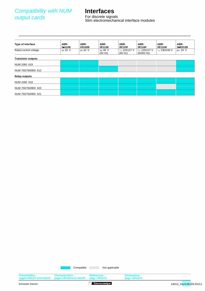
Compatibility with NUM output cards
Interfaces For discrete signalsSlim electromechanical interface modules
Presentation : Characteristics : References : Dimensions :
Transistor outputs
Relay outputs
Type of interface ABR- ABR- ABR- ABR- ABR- ABR- ABR- 2/112B 2S102B 2E112E 2E115F 2E116F 2E111M 2/B312BRated control voltage $ 24 V $ 24 V $ 48 V " 115/127 V " 120/127 V " 230/240 V $ 24 V
(50 Hz) (60 Hz) (50/60 Hz)
NUM 1060 619
NUM 750/760/800 612
NUM 1060 618
NUM 750/760/800 620
NUM 750/760/800 621
Compatible Not applicable
14013_Ver4.00-EN.fm/11
/5 page 14013/12 page 14013/13
4013_Ver4.00-EN.fm/12
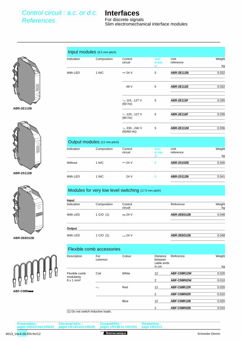
Control circuit : a.c. or d.c.References
pages 14013/2 and 14013/3 pages 14013/4 and 14013/5 p
Interfaces For discrete signalsSlim electromechanical interface modules
Input
(1) Do not switch inductive loads.
Input modules (9.5 mm pitch)
Indication Composition Control Sold Unit Weightcircuit in lots reference
of kg
With LED 1 N/C $ 24 V 5 ABR-2E112B 0.032
$ 48 V 5 ABR-2E112E 0.032
" 115...127 V 5 ABR-2E115F 0.035(50 Hz)
" 120...127 V 5 ABR-2E116F 0.035(60 Hz)
" 230...240 V 5 ABR-2E111M 0.036(50/60 Hz)
Output modules (12 mm pitch)
Indication Composition Control Sold Unit Weightcircuit in lots reference
of kg
Without 1 N/C $ 24 V 5 ABR-2S102B 0.040
With LED 1 N/C $ 24 V 5 ABR-2S112B 0.041
Modules for very low level switching (17.5 mm pitch)
Indication Composition Control Reference Weightcircuit kg
With LED 1 C/O (1) $ 24 V ABR-2EB312B 0.048
Output
With LED 1 C/O (1) $ 24 V ABR-2EB312B 0.048
Flexible comb accessories
Description For Colour Distance Reference Weightcommon between
cable endsin cm kg
Flexible comb Coil White 12 ABF-C08R12W 0.020modularity8 x 1 mm2 2 ABF-C08R02W 0.010
" Red 12 ABF-C08R12R 0.020
2 ABF-C08R02R 0.010
$ Blue 12 ABF-C08R12B 0.020
2 ABF-C08R02B 0.010
Presentation : Characteristics : Compatibility : Dimensions :
ABR-2E112B
ABR-2EB312B
ABF-C08R///
ABR-2S112B
Schneider Electric
ages 14013/6 to 14013/11 page 14013/13
Schneider Electric
Dimensions, schemes
pages 14013/2 and 14013/3 pages 14013/4 and 14013/5
Interfaces For discrete signalsSlim electromechanical interface modules
78
75
70,5
9,5
7412
74
1411
12+A1
–A2
17,5
74
78
75
70,5
63
+A1
–A2
1314
+A1
–A2
1314
A1
– A2
1314
+A1
–A2
1314
+A1
–A2
1314
78
75
70,5
78
75
70,5
63
17,5
74
Dimensions
Circuit diagrams
ABR-2E11// ABR-2S1/2B
ABR-2EB312B ABR-2SB312B
ABR-2E112B ($ 24 V) ABR-2E112E ($ 48 V) ABR-2E11/F/M (" 115...240 V)
ABR-2S102B ($ 24 V) ABR-2S112B ($ 24 V) ABR-2/B312B ($ 24 V)
Presentation : Characteristics : Compatibility : References :
14013_Ver4.00-EN.fm/13
pages 14013/6 to 14013/11 page 14013/12
Presentation
pages 14014/4 and 14014/3 pages 14014/6 and 14014/11
Interfaces For discrete signalsSlim solid state interface modules
3
2
1
4
3
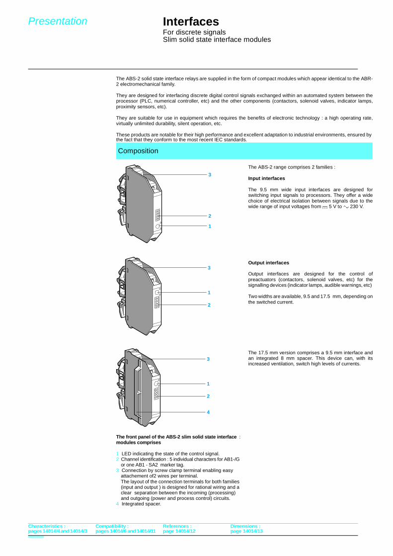
2
1
3
2
1
The ABS-2 solid state interface relays are supplied in the form of compact modules which appear identical to the ABR-2 electromechanical family.
They are designed for interfacing discrete digital control signals exchanged within an automated system between theprocessor (PLC, numerical controller, etc) and the other components (contactors, solenoid valves, indicator lamps,proximity sensors, etc).
They are suitable for use in equipment which requires the benefits of electronic technology : a high operating rate,virtually unlimited durability, silent operation, etc.
These products are notable for their high performance and excellent adaptation to industrial environments, ensured by the fact that they conform to the most recent IEC standards.
The ABS-2 range comprises 2 families :
Input interfaces
The 9.5 mm wide input interfaces are designed forswitching input signals to processors. They offer a widechoice of electrical isolation between signals due to thewide range of input voltages from $ 5 V to " 230 V.
Output interfaces
Output interfaces are designed for the control ofpreactuators (contactors, solenoid valves, etc) for thesignalling devices (indicator lamps, audible warnings, etc)
Two widths are available, 9.5 and 17.5 mm, depending onthe switched current.
The 17.5 mm version comprises a 9.5 mm interface andan integrated 8 mm spacer. This device can, with itsincreased ventilation, switch high levels of currents.
Composition
The front panel of the ABS-2 slim solid state interface :modules comprises
1 LED indicating the state of the control signal.2 Channel identification : 5 individual characters for AB1-/G
or one AB1 - SA2 marker tag. 3 Connection by screw clamp terminal enabling easy
attachement of2 wires per terminal.The layout of the connection terminals for both families (input and output ) is designed for rational wiring and a clear separation between the incoming (processing)and outgoing (power and process control) circuits.
4 Integrated spacer.
Characteristics : Compatibility : References : Dimensions :
page 14014/12 page 14014/13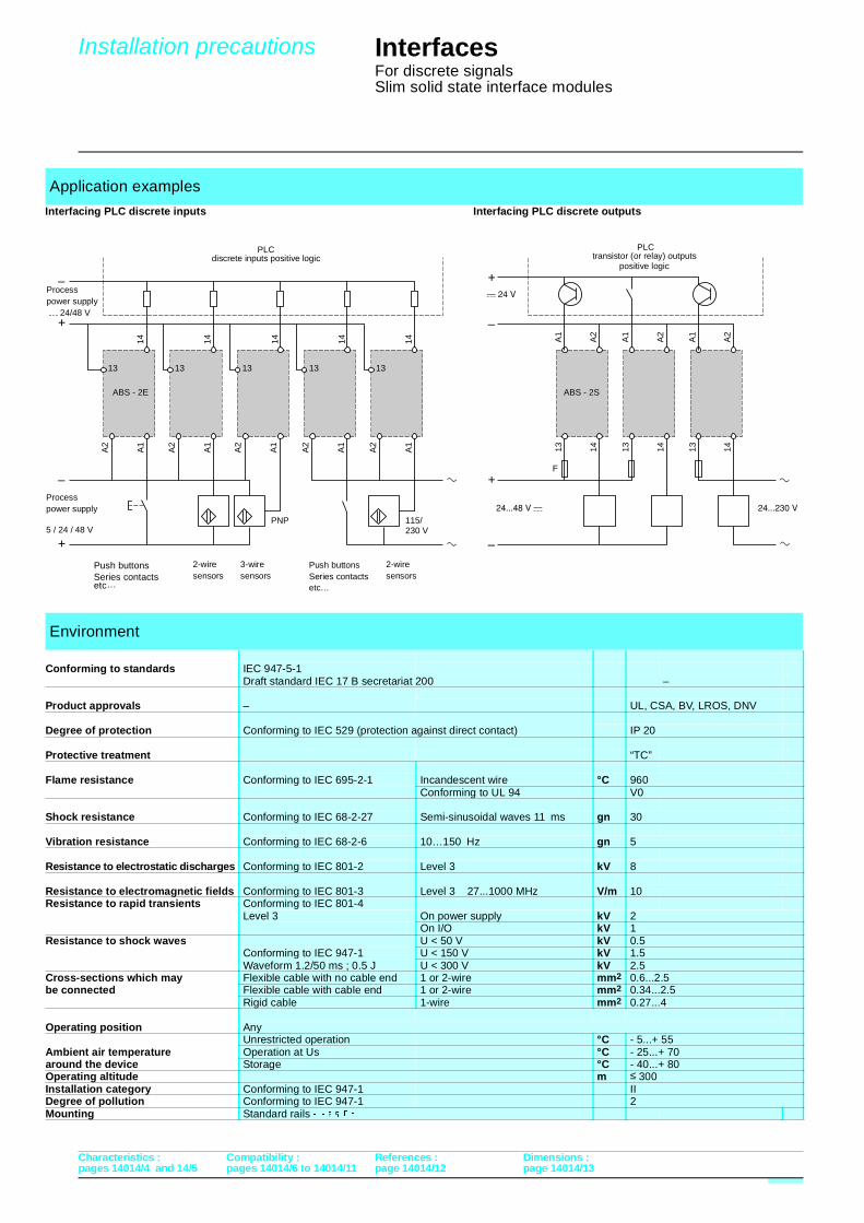
Installation precautions
pages 14014/4 and 14/5 pages 14014/6 to 14014/11
Interfaces For discrete signalsSlim solid state interface modules
–
+
–
+
–
+
–
+
A1
A2
14
13
14
13
A1
A2
A1
A2
ABS - 2E ABS - 2S
F
13 14 13 14 13 14
13
14
PNP 115/230 V
13
14
13
14A
1
A2
A1
A2
A1
A2
A1
A2
A1
A2
Application examples
Interfacing PLC discrete inputs Interfacing PLC discrete outputs
Environment
Conforming to standards IEC 947-5-1Draft standard IEC 17 B secretariat 200 –
Product approvals – UL, CSA, BV, LROS, DNV
Degree of protection Conforming to IEC 529 (protection against direct contact) IP 20
Protective treatment “TC”
Flame resistance Conforming to IEC 695-2-1 Incandescent wire °C 960Conforming to UL 94 V0
Shock resistance Conforming to IEC 68-2-27 Semi-sinusoidal waves 11 ms gn 30
Vibration resistance Conforming to IEC 68-2-6 10…150 Hz gn 5
Resistance to electrostatic discharges Conforming to IEC 801-2 Level 3 kV 8
Resistance to electromagnetic fields Conforming to IEC 801-3 Level 3 27...1000 MHz V/m 10Resistance to rapid transients Conforming to IEC 801-4
Level 3 On power supply kV 2On I/O kV 1
Resistance to shock waves U < 50 V kV 0.5Conforming to IEC 947-1 U < 150 V kV 1.5
Waveform 1.2/50 ms ; 0.5 J U < 300 V kV 2.5Cross-sections which may Flexible cable with no cable end 1 or 2-wire mm2 0.6...2.5be connected Flexible cable with cable end 1 or 2-wire mm2 0.34...2.5
Rigid cable 1-wire mm2 0.27...4
Operating position AnyUnrestricted operation °C - 5...+ 55
Ambient air temperature Operation at Us °C - 25...+ 70around the device Storage °C - 40...+ 80Operating altitude m ≤ 300Installation category Conforming to IEC 947-1 IIDegree of pollution Conforming to IEC 947-1 2Mounting Standard rails ���
PLCdiscrete inputs positive logic
Characteristics : Compatibility : References : Dimensions :
Processpower supply
5 / 24 / 48 V $
Push buttonsSeries contactsetc…
3-wiresensors
2-wiresensors
2-wiresensors
Push buttonsSeries contactsetc…
Processpower supply $ 24/48 V
PLCtransistor (or relay) outputs
positive logic
page 14014/12 page 14014/13
Characteristics
pages 14014/2 and 14014/3 pages 14014/6 and 14014/11
Interfaces For discrete signalsSlim solid state input modules
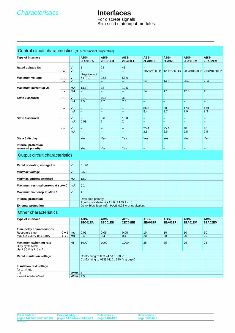
Control circuit characteristics (at 55 °C ambient temperature)
Type of interface ABS- ABS- ABS- ABS- ABS- ABS- ABS-2EC01EA 2EC01EB 2EC01EE 2EA01EF 2EA02EF 2EA01EM 2EA02EM
Rated voltage Us $ V 5 24 48 – – – –" V – – – 115/127 50 Hz 120/127 60 Hz 230/240 50 Hz 230/240 60 Hz
Negative logicMaximum voltage $ V 6 (TTL) 28.8 57.6 – – – –
" V – – – 140 140 264 264
Maximum current at Us $ mA 13.6 12 10.5 – – – –" mA – – – 14 17 12.5 15
State 1 assured $ V 3.75 16.9 36 – – – –mA 4.5 7.7 7.5 – – – –
" V – – – 86.3 90 173 173mA – – – 8.4 9.7 7.9 9.3
State 0 assured $ V 2 5.6 10.8 – – – –mA 0.09 2 2 – – – –
" V – – – 25.4 25.4 48 48mA – – – 2.5 2.5 2.5 2.5
State 1 display Yes Yes Yes Yes Yes Yes Yes
Internal protectionreversed polarity Yes Yes Yes – – – –
Output circuit characteristics
Rated operating voltage Ue $ V 5...48
Min/max voltage $ V 2/60
Min/max current switched mA 1/50
Maximum residual current at state 0 mA 0.1
Maximum volt drop at state 1 V 1
Internal protection Reversed polarityAgainst short-circuits for Ik ≤ 100 A ($)
External protection Quick-blow fuse, ref. : HA21 0.25 A or equivalent
Other characteristics
Type of interface ABS- ABS- ABS- ABS- ABS- ABS- ABS-2EC01EA 2EC01EB 2EC01EE 2EA01EF 2EA02EF 2EA01EM 2EA02EM
Time delay characteristicsResponse time 0 � 1 ms 0.05 0.05 0.05 10 10 10 10max Ue ≤ 30 V Ie ≥ 5 mA 1 � 0 ms 0.4 0.4 0.4 20 20 20 20
Maximum switching rate Hz 1000 1000 1000 25 25 25 25Duty cycle 50 %Ue ≤ 30 V Ie ≥ 5 mA
Rated insulation voltage Conforming to IEC 947-1 : 300 VConforming to VDE 0110 : 250 V group C
Insulation test voltagefor 1 minute- I/O kVrms 4 - wired interface/earth kVrms 2.5
Presentation : Compatibility : References : Dimensions :
page 14014/12 page 14014/13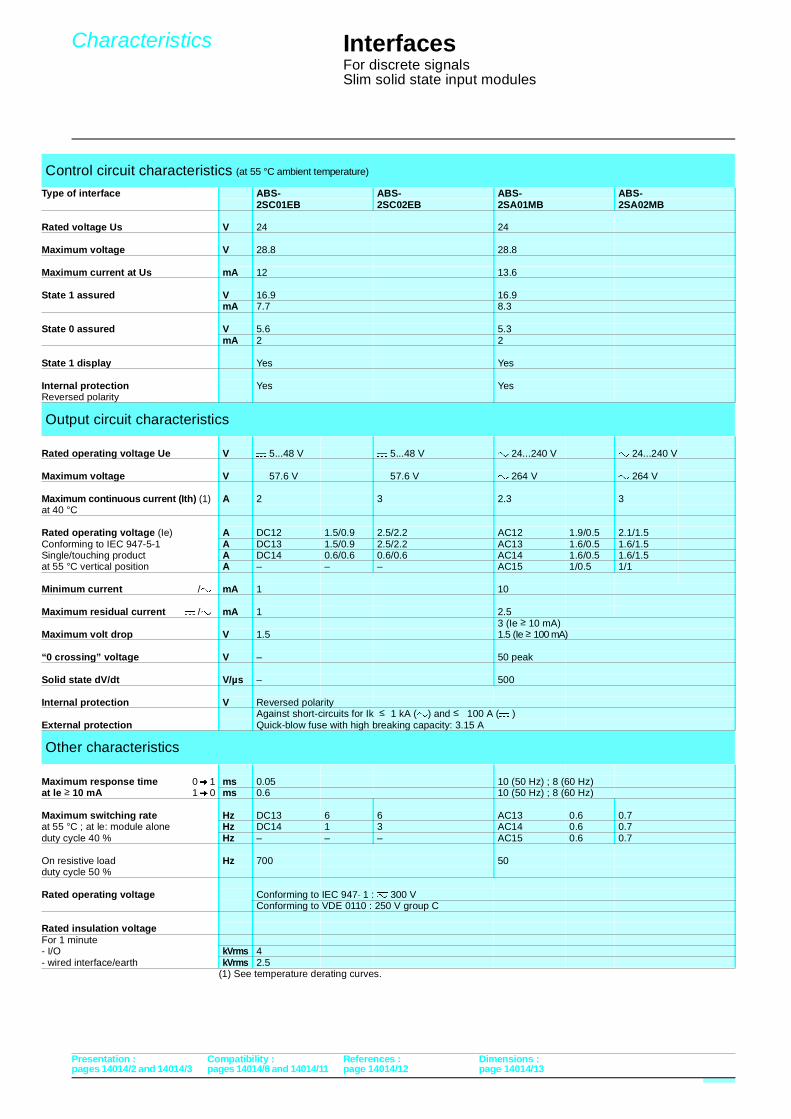
Characteristics
pages 14014/2 and 14014/3 pages 14014/6 and 14014/11
Interfaces For discrete signalsSlim solid state input modules
(1) See temperature derating curves.
Control circuit characteristics (at 55 °C ambient temperature)
Type of interface ABS- ABS- ABS- ABS-2SC01EB 2SC02EB 2SA01MB 2SA02MB
Rated voltage Us $ V 24 24
Maximum voltage V 28.8 28.8
Maximum current at Us mA 12 13.6
State 1 assured V 16.9 16.9mA 7.7 8.3
State 0 assured V 5.6 5.3mA 2 2
State 1 display Yes Yes
Internal protection Yes YesReversed polarity
Output circuit characteristics
Rated operating voltage Ue V $ 5...48 V $ 5...48 V " 24...240 V " 24...240 V
Maximum voltage V $ 57.6 V $ 57.6 V " 264 V " 264 V
Maximum continuous current (Ith) (1) A 2 3 2.3 3at 40 °C
Rated operating voltage (Ie) A DC12 1.5/0.9 2.5/2.2 AC12 1.9/0.5 2.1/1.5 Conforming to IEC 947-5-1 A DC13 1.5/0.9 2.5/2.2 AC13 1.6/0.5 1.6/1.5Single/touching product A DC14 0.6/0.6 0.6/0.6 AC14 1.6/0.5 1.6/1.5at 55 °C vertical position A – – – AC15 1/0.5 1/1
Minimum current $ /" mA 1 10
Maximum residual current $ /" mA 1 2.53 (Ie ≥ 10 mA)
Maximum volt drop V 1.5 1.5 (Ie ≥ 100 mA)
“0 crossing” voltage V – 50 peak
Solid state dV/dt V/µs – 500
Internal protection V Reversed polarityAgainst short-circuits for Ik ≤ 1 kA (") and ≤ 100 A ($ )
External protection Quick-blow fuse with high breaking capacity: 3.15 A
Other characteristics
Maximum response time 0 � 1 ms 0.05 10 (50 Hz) ; 8 (60 Hz)at le ≥ 10 mA 1 � 0 ms 0.6 10 (50 Hz) ; 8 (60 Hz)
Maximum switching rate Hz DC13 6 6 AC13 0.6 0.7at 55 °C ; at le: module alone Hz DC14 1 3 AC14 0.6 0.7duty cycle 40 % Hz – – – AC15 0.6 0.7
On resistive load Hz 700 50duty cycle 50 %
Rated operating voltage Conforming to IEC 947− 1 : 7 300 V Conforming to VDE 0110 : 250 V group C
Rated insulation voltageFor 1 minute- I/O kVrms 4- wired interface/earth kVrms 2.5
Presentation : Compatibility : References : Dimensions :
page 14014/12 page 14014/13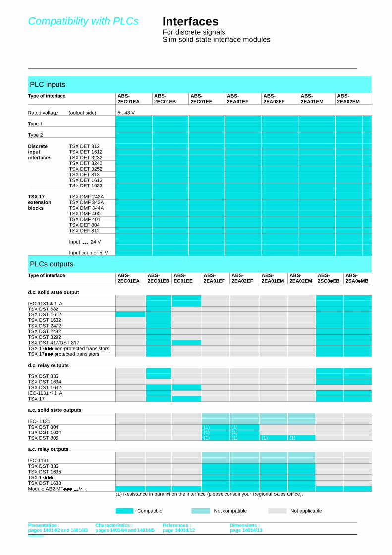
Compatibility with PLCs
pages 14014/2 and 14014/3 pages 14014/4 and 14014/5
Interfaces For discrete signalsSlim solid state interface modules
(1) Resistance in parallel on the interface (please consult your Regional Sales Office).
PLC inputs
Type of interface ABS- ABS- ABS- ABS- ABS- ABS- ABS-2EC01EA 2EC01EB 2EC01EE 2EA01EF 2EA02EF 2EA01EM 2EA02EM
Rated voltage $ (output side) 5...48 V
Type 1
Type 2
Discrete TSX DET 812input TSX DET 1612interfaces TSX DET 3232
TSX DET 3242TSX DET 3252TSX DET 813TSX DET 1613TSX DET 1633
TSX 17 TSX DMF 242Aextension TSX DMF 342Ablocks TSX DMF 344A
TSX DMF 400TSX DMF 401TSX DEF 804TSX DEF 812
Input $ 24 V
Input counter 5 V
PLCs outputs
Type of interface ABS- ABS- ABS- ABS- ABS- ABS- ABS- ABS- ABS-2EC01EA 2EC01EB EC01EE 2EA01EF 2EA02EF 2EA01EM 2EA02EM 2SC0/EB 2SA0/MB
d.c. solid state output
IEC-1131 ≤ 1 A TSX DST 882TSX DST 1612TSX DST 1682TSX DST 2472TSX DST 2482TSX DST 3292TSX DST 417/DST 817TSX 17/// non-protected transistors TSX 17/// protected transistors
d.c. relay outputs
TSX DST 835TSX DST 1634 TSX DST 1632IEC-1131 ≤ 1 ATSX 17
a.c. solid state outputs
IEC- 1131 TSX DST 804 (1) (1)TSX DST 1604 (1) (1)TSX DST 805 (1) (1) (1) (1)
a.c. relay outputs
IEC-1131TSX DST 835 TSX DST 1635 TSX 17///TSX DST 1633Module AB2-MT/// $/"
Compatible Not compatible Not applicable
Presentation : Characteristics : References : Dimensions :
page 14014/12 page 14014/13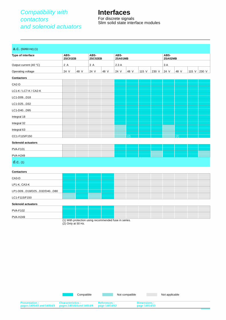
Compatibility with contactors and solenoid actuators
pages 14014/2 and 14014/3 pages 14014/4 and 14014/5
Interfaces For discrete signalsSlim solid state interface modules
(1) With protection using recommended fuse in series.(2) Only at 50 Hz.
a.c. (50/60 Hz) (1)
Type of interface ABS- ABS- ABS- ABS-2SC01EB 2SC02EB 2SA01MB 2SA02MB
Output current (40 °C) 2 A 3 A 2.3 A 3 A
Operating voltage 24 V 48 V 24 V 48 V 24 V 48 V 115 V 230 V 24 V 48 V 115 V 230 V
Contactors
CA2-D
LC1-K / LC7-K / CA2-K
LC1-D09...D18
LC1-D25...D32
LC1-D40...D95
Integral 18
Integral 32
Integral 63
CC1-F115/F150 (2) (2) Solenoid actuators
PVA-F101
PVA-H249
d.c. (1)
Contactors
CA3-D
LP1-K, CA3-K
LP1-D09...D18/D25...D32/D40...D80
LC1-F115/F150
Solenoid actuators
PVA-F102
PVA-H249
Compatible Not compatible Not applicable
Presentation : Characteristics : References : Dimensions :
page 14014/12 page 14014/13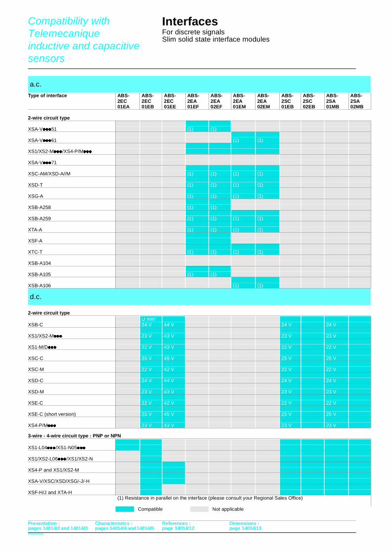
Compatibility with Telemecanique inductive and capacitive sensors
pages 14014/2 and 14014/3 pages 14014/4 and 14014/5
Interfaces For discrete signalsSlim solid state interface modules
2-wire circuit type
3-wire - 4-wire circuit type : PNP or NPN
a.c.
Type of interface ABS- ABS- ABS- ABS- ABS- ABS- ABS- ABS- ABS- ABS- ABS-2EC 2EC 2EC 2EA 2EA 2EA 2EA 2SC 2SC 2SA 2SA01EA 01EB 01EE 01EF 02EF 01EM 02EM 01EB 02EB 01MB 02MB
2-wire circuit type
XSA-V///51 (1) (1)
XSA-V///61 (1) (1)
XS1/XS2-M////XS4-P/M///
XSA-V///71
XSC-AM/XSD-A//M (1) (1) (1) (1)
XSD-T (1) (1) (1) (1)
XSG-A (1) (1) (1) (1)
XSB-A258 (1) (1)
XSB-A259 (1) (1) (1) (1)
XTA-A (1) (1) (1) (1)
XSF-A
XTC-T (1) (1) (1) (1)
XSB-A104
XSB-A105 (1) (1)
XSB-A106 (1) (1)
d.c.
U mini XSB-C 24 V 44 V 24 V 24 V
XS1/XS2-M/// 23 V 43 V 23 V 23 V
XS1-M/D/// 22 V 43 V 22 V 22 V
XSC-C 25 V 45 V 25 V 25 V
XSC-M 22 V 42 V 22 V 22 V
XSD-C 24 V 44 V 24 V 24 V
XSD-M 23 V 43 V 23 V 23 V
XSE-C 22 V 42 V 22 V 22 V
XSE-C (short version) 25 V 45 V 25 V 25 V
XS4-P/M/// 23 V 43 V 23 V 23 V
XS1-L04////XS1-N05///
XS1/XS2-L06////XS1/XS2-N
XS4-P and XS1/XS2-M
XSA-V/XSC/XSD/XSG/-J/-H
XSF-H/J and XTA-H(1) Resistance in parallel on the interface (please consult your Regional Sales Office)
Compatible Not applicable
Presentation : Characteristics : References : Dimensions :
page 14014/12 page 14014/13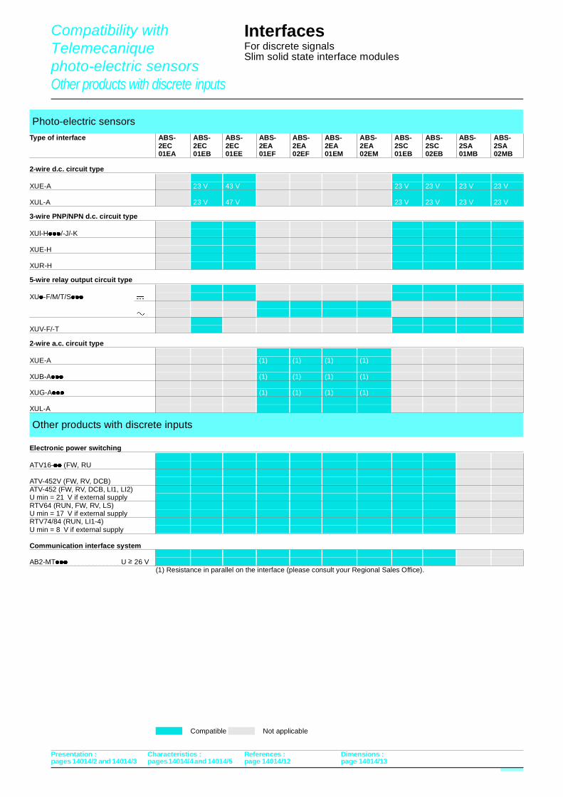
Compatibility with Telemecanique photo-electric sensors Other products with discrete inputs
pages 14014/2 and 14014/3 pages 14014/4 and 14014/5
Interfaces For discrete signalsSlim solid state interface modules
2-wire d.c. circuit type
3-wire PNP/NPN d.c. circuit type
5-wire relay output circuit type
2-wire a.c. circuit type
Electronic power switching
(1) Resistance in parallel on the interface (please consult your Regional Sales Office).
Photo-electric sensors
Type of interface ABS- ABS- ABS- ABS- ABS- ABS- ABS- ABS- ABS- ABS- ABS-2EC 2EC 2EC 2EA 2EA 2EA 2EA 2SC 2SC 2SA 2SA01EA 01EB 01EE 01EF 02EF 01EM 02EM 01EB 02EB 01MB 02MB
XUE-A 23 V 43 V 23 V 23 V 23 V 23 V
23 V 47 V 23 V 23 V 23 V 23 VXUL-A
XUl-H////-J/-K
XUE-H
XUR-H
XU/-F/M/T/S/// $
"
XUV-F/-T $
XUE-A (1) (1) (1) (1)
XUB-A/// (1) (1) (1) (1)
XUG-A/// (1) (1) (1) (1)
XUL-A
Other products with discrete inputs
ATV16-// (FW, RU
ATV-452V (FW, RV, DCB)ATV-452 (FW, RV, DCB, LI1, LI2)U min = 21 V if external supplyRTV64 (RUN, FW, RV, LS)U min = 17 V if external supplyRTV74/84 (RUN, LI1-4)U min = 8 V if external supply
Communication interface system
AB2-MT///���������������U ≥ 26 V
Compatible Not applicable
Presentation : Characteristics : References : Dimensions :
page 14014/12 page 14014/13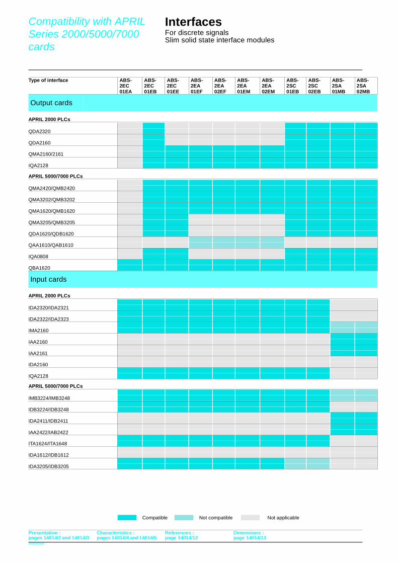
Compatibility with APRIL Series 2000/5000/7000 cards
pages 14014/2 and 14014/3 pages 14014/4 and 14014/5
Interfaces For discrete signalsSlim solid state interface modules
APRIL 2000 PLCs
APRIL 5000/7000 PLCs
APRIL 2000 PLCs
APRIL 5000/7000 PLCs
Type of interface ABS- ABS- ABS- ABS- ABS- ABS- ABS- ABS- ABS- ABS- ABS-2EC 2EC 2EC 2EA 2EA 2EA 2EA 2SC 2SC 2SA 2SA01EA 01EB 01EE 01EF 02EF 01EM 02EM 01EB 02EB 01MB 02MB
Output cards
QDA2320
QDA2160
QMA2160/2161
IQA2128
QMA2420/QMB2420
QMA3202/QMB3202
QMA1620/QMB1620
QMA3205/QMB3205
QDA1620/QDB1620
QAA1610/QAB1610
IQA0808
QBA1620
Input cards
IDA2320/IDA2321
IDA2322/IDA2323
IMA2160
IAA2160
IAA2161
IDA2160
IQA2128
IMB3224/IMB3248
IDB3224/IDB3248
IDA2411/IDB2411
IAA2422/IAB2422
ITA1624/ITA1648
IDA1612/IDB1612
IDA3205/IDB3205
Compatible Not compatible Not applicable
Presentation : Characteristics : References : Dimensions :
page 14014/12 page 14014/13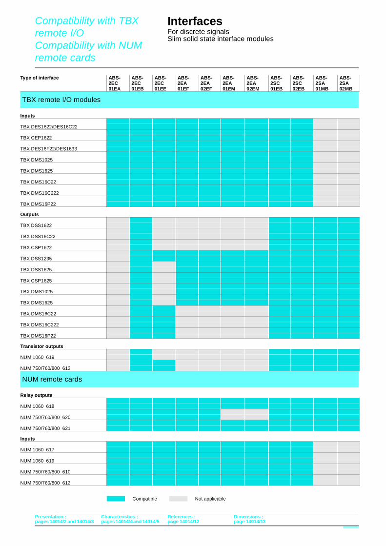
Compatibility with TBX remote I/O Compatibility with NUM remote cards
pages 14014/2 and 14014/3 pages 14014/4 and 14014/5
Interfaces For discrete signalsSlim solid state interface modules
Inputs
Outputs
Transistor outputs
Relay outputs
Inputs
Type of interface ABS- ABS- ABS- ABS- ABS- ABS- ABS- ABS- ABS- ABS- ABS-2EC 2EC 2EC 2EA 2EA 2EA 2EA 2SC 2SC 2SA 2SA01EA 01EB 01EE 01EF 02EF 01EM 02EM 01EB 02EB 01MB 02MB
TBX remote I/O modules
TBX DES1622/DES16C22
TBX CEP1622
TBX DES16F22/DES1633
TBX DMS1025
TBX DMS1625
TBX DMS16C22
TBX DMS16C222
TBX DMS16P22
TBX DSS1622
TBX DSS16C22
TBX CSP1622
TBX DSS1235
TBX DSS1625
TBX CSP1625
TBX DMS1025
TBX DMS1625
TBX DMS16C22
TBX DMS16C222
TBX DMS16P22
NUM 1060 619
NUM 750/760/800 612
NUM remote cards
NUM 1060 618
NUM 750/760/800 620
NUM 750/760/800 621
NUM 1060 617
NUM 1060 619
NUM 750/760/800 610
NUM 750/760/800 612
Compatible Not applicable
Presentation : Characteristics : References : Dimensions :
page 14014/12 page 14014/13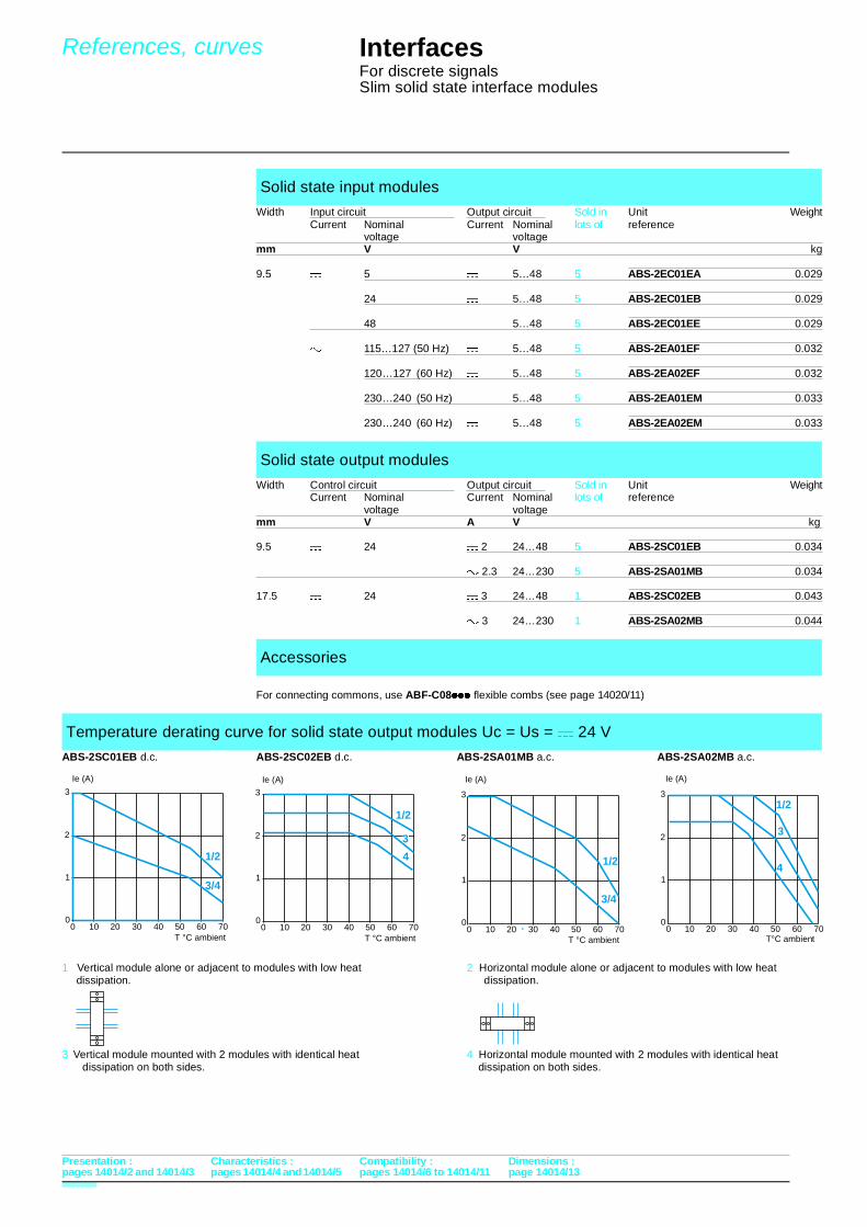
References, curves
pages 14014/2 and 14014/3 pages 14014/4 and 14014/5
Interfaces For discrete signalsSlim solid state interface modules
10 20 30 40 50 60 70
1
2
3
1/2
00
4
3
10 20 30 40 50 60 70
1
2
31/2
00
4
3
10 20 30 40 50 60 70
1
2
3
1/2
00
3/4
10 20 30 40 50 60 70
1
2
3
1/2
00
3/4
For connecting commons, use ABF-C08/// flexible combs (see page 14020/11)
Solid state input modules
Width Input circuit Output circuit Sold in Unit WeightCurrent Nominal Current Nominal lots of reference
voltage voltagemm V V kg
9.5 $ 5 $ 5…48 5 ABS-2EC01EA 0.029
24 $ 5…48 5 ABS-2EC01EB 0.029
48 $ 5…48 5 ABS-2EC01EE 0.029
" 115…127 (50 Hz) $ 5…48 5 ABS-2EA01EF 0.032
120…127 (60 Hz) $ 5…48 5 ABS-2EA02EF 0.032
230…240 (50 Hz) $ 5…48 5 ABS-2EA01EM 0.033
230…240 (60 Hz) $ 5…48 5 ABS-2EA02EM 0.033
Solid state output modules
Width Control circuit Output circuit Sold in Unit WeightCurrent Nominal Current Nominal lots of reference
voltage voltagemm V A V kg
9.5 $ 24 $ 2 24…48 5 ABS-2SC01EB 0.034
" 2.3 24…230 5 ABS-2SA01MB 0.034
17.5 $ 24 $ 3 24…48 1 ABS-2SC02EB 0.043
" 3 24…230 1 ABS-2SA02MB 0.044
Accessories
Temperature derating curve for solid state output modules Uc = Us = $ 24 V
ABS-2SC01EB d.c. ABS-2SC02EB d.c. ABS-2SA01MB a.c. ABS-2SA02MB a.c.
1 Vertical module alone or adjacent to modules with low heat 2 Horizontal module alone or adjacent to modules with low heat dissipation. dissipation.
3 Vertical module mounted with 2 modules with identical heat 4 Horizontal module mounted with 2 modules with identical heat dissipation on both sides. dissipation on both sides.
Ie (A)
T °C ambient
Presentation : Characteristics : Compatibility : Dimensions :
T °C ambient
Ie (A)Ie (A)
T °C ambient T°C ambient
Ie (A)
pages 14014/6 to 14014/11 page 14014/13
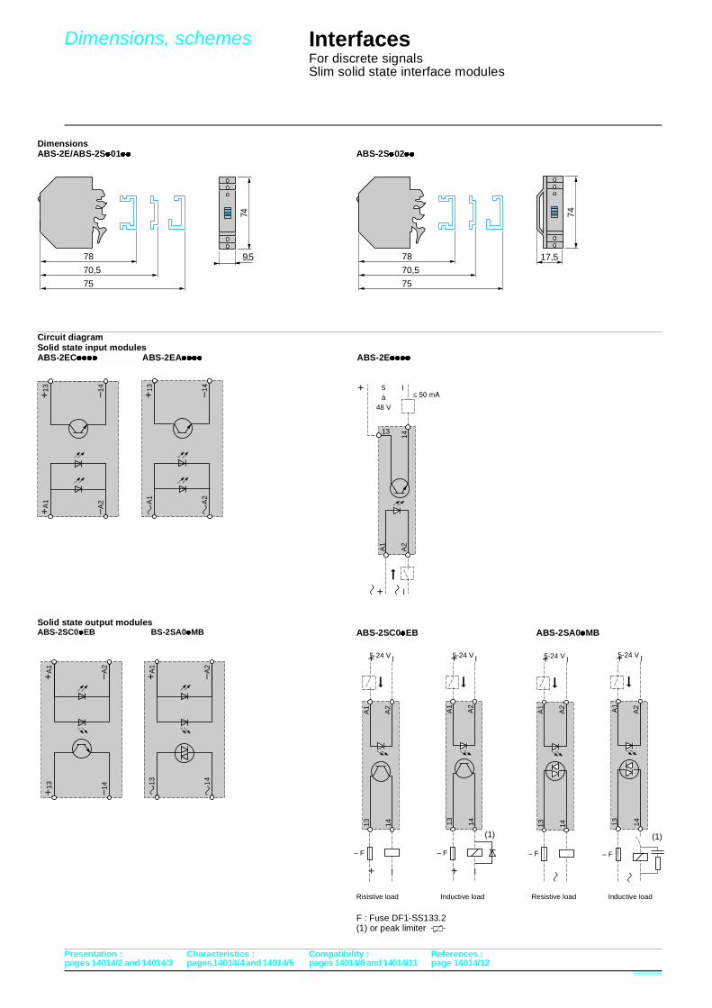
Dimensions, schemes
pages 14014/2 and 14014/3 pages 14014/4 and 14014/5
InterfacesFor discrete signalsSlim solid state interface modulesPresentation : Characteristics : Compatibility : References :
DimensionsABS-2E/ABS-2S/01// ABS-2S/02//
Circuit diagramSolid state input modulesABS-2EC////����������ABS-2EA//// ABS-2E////
Solid state output modulesABS-2SC0/EB BS-2SA0/MB ABS-2SC0/EB ABS-2SA0/MB
Risistive load Inductive load Resistive load Inductive load
F : Fuse DF1-SS133.2(1) or peak limiter
1413
A2
A1
+ –
+ –
– F
5-24 V
1413
A2
A1
+ –
+ –
– F
5-24 V
(1)
14
13
A2
A1
+ –5à
48 V
+ –
1413
A2
A1
+ –
– F
5-24 V
1413
A2A1
+ –
– F
5-24 V
(1)
+13
–14
+A
1
–A2
+A
1
–A2
+13 –1
4
78
75
70,5
17,5
74
78
75
70,5
74
9,5
A
1
A
2
+13 –1
4
1
3
1
4
+A
1
–A2
pages 14014/6 and 14014/11 page 14014/12