Embed Size (px)
Citation preview

Medium Voltage Distribution
Vacuumcircuit-breakerType VA, VAA, VAH, VXA, VXB, VXC
Selection List

Delivery conditionsThe General Conditions of Delivery as amended shall apply.
IllustrationsThe illustrations are not bin-

3VA Auswahlliste EN
VA Table of contents
■ Introduction .......................................................................................... 4 ■ Mechanical design ............................................................................... 5 ■ Optional equipment ............................................................................. 7 ■ Vacuum circuit-breaker with reclosing facility (auto-reclosure) ..... 8 ■ Specifications and tests ...................................................................... 9
□ Specifications, Tests, Environmental and operating conditions ....... 9 □ Numbers of breaking operations up to the summation current limit .......... 10 □ Vacuum tester VT ............................................................................11
■ Selection tables .................................................................................. 12 □ Vacuum circuit-breakers VA, VAA 12 kV ...........................................12 □ Vacuum circuit-breakers VA, VAA 17.5 kV ........................................14 □ Vacuum circuit-breakers VA, VAA 24 kV ...........................................16 □ Vacuum circuit-breakers VA 36 kV ....................................................18 □ Vacuum circuit-breakers for railway applications VXA, B, 17.5 / 25 / 27.5 kV ..20 □ Vacuum circuit-breakers for high numbers of switching operations
VXC, 24 / 36 / 38 kV .............................................................................22 □ Vacuum circuit-breakers for high currents VAH ................................24
■ Electric circuit diagrams .................................................................. 26 ■ Vacuum circuit-breaker dimensions ................................................................32 ■ Transport............................................................................................. 50

4 VA Auswahlliste EN
VA
General DescriptionVA and VAA vacuum circuitbreakers are front-mounted switches for application in medium-voltage indoor switchgear. They can be fixed installations in switchgear or can be mounted on a switchgear truck, a drawing-unit truck or a drawing unit. In railway applications, vacuum circuitbreakers VXA or VXB (single-/ two-pole units respectively) are used. VXC circuit-breakers which are designed for an especially high number of mechanical and electrical switching operations are suitable to operate electric melting furnaces. Vacuum circuit-breakers are capable of performing all switching operations and tasks encountered in industrial plants and distribution networks or in railway applications, especially for operation of:
short-circuit currents
underground and overhead
lines
motors
transformers
generators
capacitors
Essential Features ■ High number of mechanical and electrical switching operations ■ No critical current range ■ Long service life ■ High switching capacity reserve ■ Minimum maintenance
Introduction
VXA vacuum circuit-breaker Rated voltage 17.5 kVRated short-circuit breaking current 31.5 kA
VAA vacuum circuit-breakers Rated voltage 12 kVRated short-circuit breaking current 25 kA
VA vacuum circuit-breakers Rated voltage 12 kVRated short-circuit breaking current 50 kA

5VA Auswahlliste EN
VA Mechanical design
ApplicationVacuum circuit-breakers are designed as front switches. The three-pole VA and VAA vacuum circuit-breakers master all switching cases occurring in medium-voltage systems. The VXA and VXB vacuum types satisfy specific circuit-breaker requirements. VXA vacuum circuit-breakers are single-pole, VXB types feature two poles, both types being mainly suited for railway applications. Threepole vacuum circuit-breakers VXC are used for extremely high operating frequencies, as are required e.g. for furnaces. Vacuum circuit-breakers can be fixed installations in switchgear or can be mounted on a drawing unit, a drawing-unit truck or a switchgear truck.
Design and method of operationEach of the switch poles with 1 interrupter chamber per phase is fastened to a common base frame with 2 cast-resin post insulators. All drive components, auxiliary and release devices are located in the base frame which is designed as a closed housing. Vacuum circuit- breakers can be equipped with control switches, auxiliary releases, secondary releasesand undervoltage releases, as required.Vacuum circuit-breakers are equipped with a snap-action mechanism with manually or electrically operated spring charging motor and can beequipped at choice with a reclosing facility (auto-reclosure).Power transmission between the energy-storing device and the switch poles which is required for switching ON and OFF is effected by means ofan operating rod made of highquality glass-fibre reinforced insulating material which is largely free of constraints while the vacuum circuit-breaker is ON.
VA 12 kV - View: Operating and drive side
VA 12 kV - View: Pole sections with vacuum interrupter chambers

6 VA Auswahlliste EN
VA
Pole SectionThe pole section is of extremely robust design. The solid support provides for a suspension free of external forces for the interrupter chamber. Due to this statically closed support system, the axial forces produced on closingand opening only act on the contact system, whereas the vacuum interrupter chamber remains free of constraints. The power transmission acts from the contact spring onto the moving contact via a lever system with pendulum rod to make sure the closing and opening forces are applied in precisely axial direction.
Drive MechanismThe drive mechanism has been designed as a making/breaking spring mechanism. The closing spring of the making storedenergy mechanism is charged either via an electric motor installed in the drive housing or by hand using an insertable crank. If the electric motor‘s power supply fails, the spring can still be charged at any time via the crank. The openingspring is charged during the closing operation (ON). Once closing is concluded, the closing spring - now discharged - can be charged again by the spring-charging motor automatically or by hand. In this state, the drive mechanism is ready to perform the operating sequence O–t’–CO. Thechargedclosing spring can eitherbe released by hand, by actuation of the ON pushbutton, or by a shunt closingrelease installed in the drive box. The opening procedure is initiated by actuation of the OFF pushbutton or via a shunt opening release, an undervoltage release or a secondary release.
VA pole section
Mechanical design (contd.)
7VA Auswahlliste EN
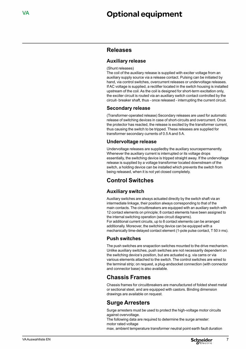
VA Optional equipment
Releases
Auxiliary release(Shunt releases)The coil of the auxiliary release is supplied with exciter voltage from an auxiliary supply source via a release contact. Pulsing can be initiated by hand, via control switches, overcurrent releases or undervoltage releases.If AC voltage is supplied, a rectifier located in the switch housing is installed upstream of the coil. As the coil is designed for short-term excitation only, the exciter circuit is routed via an auxiliary switch contact controlled by the circuit- breaker shaft, thus - once released - interrupting the current circuit.
Secondary release(Transformer-operated release) Secondary releases are used for automatic release of switching devices in case of short-circuits and overcurrent. Once the protector has reacted, the release is excited by the transformer current, thus causing the switch to be tripped. These releases are supplied for transformer secondary currents of 0.5 A and 5 A.
Undervoltage releaseUndervoltage releases are suppliedby the auxiliary sourcepermanently.Whenever the auxiliary current is interrupted or its voltage drops essentially, the switching device is tripped straight away. If the undervoltagerelease is supplied by a voltage transformer located downstream of the switch, a holding device can be installed which prevents the switch frombeing released, when it is not yet closed completely.
Control Switches
Auxiliary switchAuxiliary switches are always actuated directly by the switch shaft via an intermediate linkage, their position always corresponding to that of themain contacts. The circuitbreakers are equipped with an auxiliary switch with 12 contact elements on principle; 8 contact elements have been assigned to the internal switching operation (see circuit diagrams).For additional current circuits, up to 8 contact elements can be arranged additionally. Moreover, the switching device can be equipped with a mechanically time-delayed contact element (1-pole pulse contact, T 50 ≥ ms).
Push switchesThe push switches are snapaction switches mounted to the drive mechanism. Unlike auxiliary switches, push switches are not necessarily dependent on the switching device‘s position, but are actuated e.g. via cams or via various elements attached to the switch. The control switches are wired to the terminal strip; on request, a plug-andsocket connection (with connectorand connector base) is also available.
Chassis FramesChassis frames for circuitbreakers are manufactured of folded sheet metal or sectional steel, and are equipped with castors. Binding dimension drawings are available on request.
Surge ArrestersSurge arresters must be used to protect the high-voltage motor circuits against overvoltage.The following data are required to determine the surge arrester: motor rated voltage max. ambient temperature transformer neutral point earth fault duration

8 VA Auswahlliste EN
VA Vacuum circuit-breakerwith reclosing facility (auto-reclosure)
All vacuum circuit-breakers can be supplied with reclosing facility (KU).
Method of operationIf a short-circuit occurs, an overcurrent relay issues a pulse to the shunt opening release, after expiry of the preset instantaneous zone, switching the circuit-breaker OFF.Once the preset dead time has expired, an ON command is issued to the shunt closing release via a NO contact of the auto-reclosing relay.If the short-circuit is still present, another OFF command is issued by the overcurrent relay, and the circuit-breaker is switched off for good. The auto-reclosing relay does not issue another ON command.The vacuum circuit-breaker‘s economic efficiency is based on its excellent maintenance characteristics. The interrupter chamber need not normally be replaced during the switching device‘s service life. The admissiblenumbers of switching operations at different breaking currents are indicated in the diagrams.The high value of the service life is considered in comparisons of economic efficiency with other switch principles, especially in applications requiringhigh operating frequencies. In other cases, maintenance of the drive mechanism and the expense required to this effect for electric isolationdecisively affect availability and maintenance costs. The requirement of having a single inspection of the drive mechanism after 10,000 operatingcycles or 20 years of operation means that maintenance expense is reduced to a minimum.The VXC vacuum circuit-breakers can be used for extremely high numbers of operating cycles, e.g. as furnace-type switches.After 25,000 switching operations, the drive mechanism should be checked and the vacuum interrupter chambers replaced at the same time. The mechanical service life of the VXC vacuum circuit-breaker is 75,000 operating cycles.
Rated operating sequencesRated operating sequence Designation Specifications Remarks
0–3 min – CO – 3 min – COwithout reclosingfacility
IEC 62271-100see Selection Tables
0–0,3s – CO – 3 min – COwith reclosingfacility
IEC 62271-100see Selection Tables
CO – 15s – COIECANSI - Standard C37
see Selection Tables, column"with reclosing facility"
0-0,3s – CO – 15s - CO bis0-0,3s – CO – 15s - CO – 15s – CO – 15s – CO
reclosing cyclesANSI - Standard C37
on request
0-15s –C’O – 15s – C’O - 15s – C’O – 15s – C’O
Thunderstormcycle
Customerspecification
on request
0-15s –C’O – 15s – C’O - 15s – C’O – 15s – C’O
15s - C’O – 15s – C’O - 15s – C’O – 15s - C’O – 15 – C’O
Thunderstormcycle
Customerspecification
on request
C Switching ON at rated short-circuit making currentC' Switching ON at rated currentO Switching OFF at rated short-circuit breaking current

9VA Auswahlliste EN
VA Specificationsand tests
SpecificationsThe three-pole vacuum circuit- breakers VA, VAA, VXC, VAH meet the specifications for AC switchgear for voltages above 1 kV in acc. with IEC62271-100, and also comply to a large extent, regarding their switching and insulating level, with the requirements of ANSI C37... 1) The single-pole vacuum circuit-breaker VXA/VXB complies with the requirements regarding AC switching devices for voltages above 1 kV in acc. with IEC 62271-100 as well as with the railway standard EN 50152-1.
TestsVacuum circuit-breakers have proved their suitability in type tests and in comprehensive test series during the development phase. The tests were performed in the company‘s own high-performance test laboratories and in neutral institutes such as FGH and KEMA. The tests not only covered compliance with the specified type tests, but also various special requirements, the determination of service life characteristics for the interrupter chambers and the suitability in type-tested switchgear; moreover, complex tests in power supply systems were performed. Reliability, operating safety and the mechanical function of the switching devices were checked in endurance tests.1) on request
Environmental and operating conditionsCircuit-breakers VA, VAA, VAH, VXA, VXB and VXC may only be operated under normal operating conditions according to IEC 60694.Operation under conditions deviating from these is only admissible upon consultation and with the approval of the manufacturer.
Rated voltage, insulating level, specificationsVoltage designationand insulating ability within the
Ratedvoltage
Ratedlightningimpulsewithstandvoltage
Rated powerfrequencywithstandvoltage
Type designation kV kV kV
124.767.212
606075
192028
1713.8 95 3815 95 38
VA 17.5 95 38VAAVXC
24 15.424
110125
5050
25.8 150 60
3627.636
125170
6070
3838 150 8038 200 80
17 17.5 170 70VXA 25 25 170 70VXB 27 27.5 250 105
Ambient conditionsAmbient conditionsTemperature class: „Minus 5 indoors” optional: “minus 25 indoors”)Min./max.
-5 / 40 °Cambient temperatureAverage value over 24 hours (max.) 35 °CMaximum installation altitude above sea-level higher installation altitudes possible on request) 1000 m

10 VA Auswahlliste EN
VA Specificationsand tests (contd.)
Numbers of Breaking operations up to the summation current limitThe diagrams define exclusively the admissible summation current limit.They indicate whether the vacuum interrupter chambers need to be replaced.Depending on the rated normal voltage, not all the combinations shown may be possible. The data for the rated normal current and short-circuit opening current are indicated in the Selection Tables as of page 12.Depending on the rated normal
Vacuum circuit-breakers VA, VAA, VXA, VXB
Vacuum circuit-breaker VXC
Vacuum circuit-breaker Typ VA
Ir [A] Isc [kA]25 31.5 40 50
630 ■
1250 ■ ■ ■
1600 ■ ■ ■ ■
2000 ■ ■ ■ ■
2500 ■ ■ ■ ■
Vacuum circuit-breaker Typ VAA
Ir [A] Isc [kA]16 20 25
630 ■ ■
1250 ■ ■ ■
Vacuum circuit-breaker Typ VXC
Ir [A] Isc [kA]25 31.5
1250 ■ ■
2500 ■ ■
Rated normal current Ir 630 A, 1250 A, 1600 A, 2000 A, 2500 A
30 000
10 0005000
1000500
10050
10Ir ISC
Breaking current log Ia
Num
ber o
f bre
akin
g ope
ratio
ns n
Rated normal current Ir 1250 A, 2500 A
30 00025 000
10 0005000
1000500
10050
10Ir ISC
Breaking current log Ia
Num
ber o
f bre
akin
g ope
ratio
ns n
Ir = Rated (normal) current [A]Isc = Rated short-circuit breaking current [kA]

11VA Auswahlliste EN
VA Specificationsand tests (contd.)
Vacuum tester VT 60 (Optional)The vacuum tester VT 60 can be used to verify the dielectric strength of the contact gap of the vacuum circuit-breakers.This test is also used to determine indirectly whether the vacuum interrupter chambers are subject to an inside pressure of ≤10 -2 mbar.This unit enables the operator
■ to determine easily and quickly, without disassembling the switching device, ■ without extensive testing ■ with a sufficient precision whether the vacuum level in the interrupter
chamber still satisfies the requirements.
Special features ■ Straightforward handling ■ Compact design (unit incl. case approx. in the size of a briefcase) ■ Rugged design ■ Low weight (approx. 8 kg) ■ Low cost of investment
Physical bases of the test methodThe dielectric strength of the vacuum contact gap depends on the chamber pressure „P“.Thus, the vacuum can be checked indirectly by means of voltage measurement. The test point „A“ has been arranged conveniently so that it features a sufficient distance from point „B“ (state with the chamber filledwith air), but so that the vacuum interrupter chamber is not subjected to an unnecessarily high load.
Performance of the auditAfter connecting the vacuum tester VT 60 to the circuitbreaker to be checked, the test can be performed easily and quickly:
■ Select the test voltage (40 or 60 kV) ■ Switch on power supply; the red warning lamp „Attention
□ high voltage“ lights up. ■ At the same time, turn knobs „Test“ with your left and right hands to their
stop in the direction of the arrow and wait for a few seconds for the lamps „not faulty“ or „faulty“ to light up.If the green lamp (not faulty) goes on, the test is completed, the vacuum chamber can be considered to be functional.
■ If the red lamp goes on, the test is repeated twice. If the green lamp does not go on even after the 3rd attempt, the vacuum interrupter chamber is considered to be faulty.The vacuum tester VT 60 thus permits straightforward, quick and reliable testing of highquality switching devices.
Technical data of vacuum tester VT 60System voltage switchable 220 V WS, 120/130 V WS
Frequency of mains voltage 50/60 Hz
Output voltage (0 …– 10%) switchable – 40 kV DC voltage – 60 kV DC voltage
Ripple content of DC voltage ≤ 3%
Short circuit current ≤ 33 mA
Discharge time of high-voltage circuit ≤ 0.3 sec.
LV fuse Micro-fuse 0.5 A slow-blowing
Weight incl. case approx. 8 kg
Dimensions of case 350 x 315 x 175 mm
Dielectric strength depending on the chamber pressurePChamber pressurePo Atmospheric pressurePp Chamber pressure on passing the voltage testUd Disruptive discharge voltageUp Test voltage

12 VA Auswahlliste EN
VA Selection tables
Vacuum circuit-breakers VA, VAA 12 kV
*) promised also for 800 A1) in case of class „minus 25 indoors“: extend closing time and opening time by 3 ms2) admissible tolerance range, no manufacturing tolerance, current value of one specimen, see routine test report
Type
VAA
Pole
cen
ter s
paci
ng
506/12mm160
Rated insulation
level
Rat
ed v
olta
ge
Rat
ed p
ower
freq
uenc
yw
ithst
and
volta
ge
kV
12
kV
28
Rat
ed li
ghtn
ing
impu
lse
with
stan
d vo
ltage
Rat
ed fr
eque
ncy
kV
75
Hz50/60
Rated short-circuit
breaking current
Rat
ed (n
orm
al) c
urre
nt
Rat
ed p
eak
with
stan
d cu
rrent
at 5
0/60
Hz
A 630 *)
kA
50/52
Rat
ed s
hort
-tim
e cu
rren
t3 s
Rat
ed s
hort
-circ
uit
curr
ent a
t rat
ed v
olta
ge
in k
V
7.2kA
20
kA
20
12
Perc
enta
ge v
alue
of t
he
DC
com
pone
nt
kA
20
%
40
Cab
le b
r eak
ing
curr
ent
Low
ind.
cur
rent
s
A
25
A
10 A for
trans-formers
in no-load
state
Bre
akin
g cu
rren
t und
er
out-o
f-pha
se c
ondi
tions
kA
5VAAVAAVAAVAA
506/125012/12
210160
5012/12636/12
210160
VAAVAAVAAVA
636/126312/12
210160
6312/12806/12
210160
12 28
50/6050/60
75
50/6050/60
12 28
50/6050/60
75
50/6050/60
630 *)12501250
630 *)
63/65 25 25 630 *)12501250
630 *)80/82 31,5 31,5
25 40 25
31,5 38 25
6,3
8VAVAVAVA
8012/12806/12
160210
8012/128016/12
210210
VAVAVAVA
8020/128025/12
210210
8031/128031/12
210210
12 28 75
50/6050/6050/6050/6050/6050/60
5060
VAVAVAVA
8031/1210012/12
275210
10016/1210020/12
210210
VAVAVAVA
10025/1210031/12
210210
10031/1210031/12
210275
12 28 75
50/6050/6050/6050/6050/60
5060
50/60
1250 630 *)
80/85
12501600
31,5/34 342000250030002900
31,5 41 25
31501250
100/104
16002000
40 402500300029003150
40 41 25
8
10
VAVAVAVA
12512/1212516/12
210210
12520/1212525/12
210210
VAVAVA
12531/1212531/12
210210
12531/12 275
12 28 75
50/6050/6050/6050/60
5060
50/60
12501600
125/13020002500 50 50
300029003150
50 40 25 12,5
Rated operatingsequence
O -
3 m
in -
CO
- 3
min
- C
O
O -
0.3
s - C
O -
3 m
in -
CO
CO
- 15
s -
CO
Switching operations without inspection
mechanical electrical
O -
0.3
s - C
O -
15 s
- C
O
Driv
e
10000
Inte
rrup
ter c
ham
ber
with
rate
d (n
orm
al) c
urre
nt
30000 10000
Operating times with release
25 W 160 W 160 W
with
rate
d sh
ort-c
ircui
tcu
rren
t
Min
./max
. ope
ning
tim
e
100
ms
45/65
Min
./max
. ope
ning
tim
e2)
Min
./max
. clo
sing
tim
e2)
ms
31/50
ms
35/70
Command timeswith release
25 W160 W160 W
Arc
dur
atio
n
OFF
ms
6 bis 12
ms
50
OFF
ON
ms
20
ms
20
Cha
rgin
g tim
e fo
r mot
or
driv
e m
echa
nism
Part
ition
s
s
≤ 5
Wei
ght
kg
105
10000 30000 10000
10000 30000 10000
100 45/65 31/50 35/70
100 45/65 31/50 35/70
6 bis 12 50 20 20
6 bis 12 50 20 20
–
≤ 5
–
105–
≤ 9–
115
10000 30000 10000
10000 30000 10000
100 45/65 30/50 35/70 6 bis 12 50 20 20
100 45/65 30/50 35/70 6 bis 12 50 20 20
≤ 9≤ 9 –≤ 9≤ 9
––
115115115115
≤ 12≤ 12
–
≤ 12≤ 12
125125140140
≤ 12≤ 9 –≤ 9≤ 12
––
140115115125
≤ 12≤ 12≤ 12≤ 12
125140140140
10000 30000 10000 100 45/65 30/50 35/70 6 bis 12 50 20 20
≤ 12≤ 12
––
≤ 12≤ 12
––
125125125125
≤ 12≤ 12≤ 12
140140140

13VA Auswahlliste EN
VA
Type
VAA
Pole
cen
ter s
paci
ng
506/12mm160
Rated insulation
level
Rat
ed v
olta
ge
Rat
ed p
ower
freq
uenc
yw
ithst
and
volta
ge
kV
12
kV
28
Rat
ed li
ghtn
ing
impu
lse
with
stan
d vo
ltage
Rat
ed fr
eque
ncy
kV
75
Hz50/60
Rated short-circuit
breaking current
Rat
ed (n
orm
al) c
urre
nt
Rat
ed p
eak
with
stan
d cu
rrent
at 5
0/60
Hz
A 630 *)
kA
50/52
Rat
ed s
hort
-tim
e cu
rren
t
3 s
Rat
ed s
hort
-circ
uit
curr
ent a
t rat
ed v
olta
ge
in k
V
7.2kA
20
kA
20
12
Perc
enta
ge v
alue
of t
he
DC
com
pone
nt
kA
20
%
40
Cab
le b
r eak
ing
curr
ent
Low
ind.
cur
rent
s
A
25
A
10 A for
trans-formers
in no-load
state
Bre
akin
g cu
rren
t und
er
out-o
f-pha
se c
ondi
tions
kA
5VAAVAAVAAVAA
506/125012/12
210160
5012/12636/12
210160
VAAVAAVAAVA
636/126312/12
210160
6312/12806/12
210160
12 28
50/6050/60
75
50/6050/60
12 28
50/6050/60
75
50/6050/60
630 *)12501250
630 *)
63/65 25 25 630 *)12501250
630 *)80/82 31,5 31,5
25 40 25
31,5 38 25
6,3
8VAVAVAVA
8012/12806/12
160210
8012/128016/12
210210
VAVAVAVA
8020/128025/12
210210
8031/128031/12
210210
12 28 75
50/6050/6050/6050/6050/6050/60
5060
VAVAVAVA
8031/1210012/12
275210
10016/1210020/12
210210
VAVAVAVA
10025/1210031/12
210210
10031/1210031/12
210275
12 28 75
50/6050/6050/6050/6050/60
5060
50/60
1250 630 *)
80/85
12501600
31,5/34 342000250030002900
31,5 41 25
31501250
100/104
16002000
40 402500300029003150
40 41 25
8
10
VAVAVAVA
12512/1212516/12
210210
12520/1212525/12
210210
VAVAVA
12531/1212531/12
210210
12531/12 275
12 28 75
50/6050/6050/6050/60
5060
50/60
12501600
125/13020002500 50 50
300029003150
50 40 25 12,5
Rated operatingsequence
O -
3 m
in -
CO
- 3
min
- C
O
O -
0.3
s - C
O -
3 m
in -
CO
CO
- 15
s -
CO
Switching operations without inspection
mechanical electrical
O -
0.3
s - C
O -
15 s
- C
O
Driv
e
10000
Inte
rrup
ter c
ham
ber
with
rate
d (n
orm
al) c
urre
nt
30000 10000
Operating times with release
25 W 160 W 160 W
with
rate
d sh
ort-c
ircui
tcu
rren
t
Min
./max
. ope
ning
tim
e
100
ms
45/65
Min
./max
. ope
ning
tim
e2)
Min
./max
. clo
sing
tim
e2)
ms
31/50
ms
35/70
Command timeswith release
25 W160 W160 W
Arc
dur
atio
n
OFF
ms
6 bis 12
ms
50
OFF
ON
ms
20
ms
20
Cha
rgin
g tim
e fo
r mot
or
driv
e m
echa
nism
Part
ition
s
s
≤ 5
Wei
ght
kg
105
10000 30000 10000
10000 30000 10000
100 45/65 31/50 35/70
100 45/65 31/50 35/70
6 bis 12 50 20 20
6 bis 12 50 20 20
–
≤ 5
–
105–
≤ 9–
115
10000 30000 10000
10000 30000 10000
100 45/65 30/50 35/70 6 bis 12 50 20 20
100 45/65 30/50 35/70 6 bis 12 50 20 20
≤ 9≤ 9 –≤ 9≤ 9
––
115115115115
≤ 12≤ 12
–
≤ 12≤ 12
125125140140
≤ 12≤ 9 –≤ 9≤ 12
––
140115115125
≤ 12≤ 12≤ 12≤ 12
125140140140
10000 30000 10000 100 45/65 30/50 35/70 6 bis 12 50 20 20
≤ 12≤ 12
––
≤ 12≤ 12
––
125125125125
≤ 12≤ 12≤ 12
140140140
Selection tables (contd.)

14 VA Auswahlliste EN
VA Selection tables (contd.)
Vacuum circuit-breakers VA, VAA 17.5 kV
*) promised also for 800 A1) in case of class „minus 25 indoors“: extend closing time and opening time by 3 ms2) adm. tolerance range, no manufacturing tolerance, current value of one specimen, see routine test report
Type
VAA
Pole
cen
ter s
paci
ng
506/17mm160
Rated insulation
level
Rat
ed v
olta
ge
Rat
ed p
ower
freq
uenc
y w
ithst
and
volta
ge
kV
17
kV
38
Rat
ed li
ghtn
ing
impu
lse
with
stan
d vo
ltage
Rat
ed fr
eque
ncy
kV
95
Hz50/60
Rated short-circuit breaking
current
Rat
ed (n
orm
al) c
urre
nt
Rat
ed p
eak
with
stan
d cu
rren
tat
50/
60 H
z
A 630 *)
kA
50/52
Rat
ed s
hort
-tim
e cu
rren
t
3 s
Rat
ed s
hort
-circ
uit c
urre
nt a
t ra
ted
volta
ge in
kV
15kA
20
kA17.5
Perc
enta
ge v
alue
of t
he D
C
com
pone
nt
kA
20
%
40
Cab
le b
reak
ing
curr
ent
Low
ind.
cur
rent
s
A
31.5
A
10 A for
trans-formersin no-loadstate
Bre
akin
g cu
rren
t und
er
out-o
f-pha
se c
ondi
tions
kA
5
VAAVAAVAAVAA
506/17506/17
210275
5012/175012/17
160210
VAAVAAVAAVAA
5012/17636/17
275160
636/17636/17
210275
50/6050/6050/6050/60
17 38 95
50/6050/6050/6050/60
630 *) 630 *) 125012501250
630 *)
63/65
630 *) 630 *)
25 25 40 31.5 6,3VAAVAAVAAVA
6312/176312/17
160210
6312/176320/17
275210
VAVAVAVA
8012/178012/17
210275
8016/178016/17
210275
50/6050/6050/6050/60
17 38 95
50/6050/6050/6050/60
VAVAVAVA
8020/178020/17
210275
8025/178025/17
210275
VAVAVAVA
8031/178031/17
210210
8031/1710020/17
275210
50/6050/6050/6050/60
17 38
5060
95
50/6050/60
125012501250200012501250
80/82
16001600
31.5 31.5 41 31.5200020002500250030002900 80/82
31502000
100/104
31.5
40
31.5 42
40 41
31.5
31.5
8
8
10VA 10025/17 210 50/60 2500
Rated operating sequence
O -
3 m
in -
CO
- 3
min
- C
O
O -
0.3
s - C
O -
3 m
in -
CO
CO
- 15
s -
CO
Number of operating cycles without overhaulmechanical electrical
O -
0.3
s - C
O -
15 s
- C
O
Driv
e m
echa
nism
10000
Inte
rrup
ter c
ham
ber
with
rate
d (n
orm
al) c
urre
nt
30000 10000
Operating timeswith release
25 W 160 W 160 W
with
rate
d sh
ort-c
ircui
t cu
rren
t
Min
./Max
. op
enin
g tim
e 2)
100
ms
45/65
Min
./Max
. op
enin
g tim
e 2)
Min
./Max
. cl
osin
g tim
e 2)
ms
31/50
ms
35/70
Command timeswith release
25 W 160 W 160 W
Arc
dur
atio
n
OFF
ms
6 to 14
ms
50
OFF
ON
ms
20
ms
20
Cha
rgin
g tim
e fo
r m
otor
driv
e m
echa
nism
Part
ition
s
s
≤ 5
Wei
ght
kg
105
10000 30000 10000 100 45/65 31/50 35/70 6 to 14 50 20 20
––
––
––
10000 30000 10000
10000
10000
30000 10000
30000 10000
100 45/65 30/50 35/70 6 to 14 50 20 20
100 45/65
100 45/65
30/50 35/70
30/50 35/70
6 to 14 50
6 to 14 50
20 20
20 20
≤ 5–
≤ 12–
105
130≤ 9≤ 9
––
≤ 9≤ 9 –
115115115115
≤ 12≤ 12 –≤ 12≤ 12 –
125125125125
≤ 12≤ 12≤ 12≤ 12
140140140125
≤ 12 125

15VA Auswahlliste EN
VA Selection tables (contd.)
Type
VAA
Pole
cen
ter s
paci
ng
506/17mm160
Rated insulation
level
Rat
ed v
olta
ge
Rat
ed p
ower
freq
uenc
y w
ithst
and
volta
ge
kV
17
kV
38
Rat
ed li
ghtn
ing
impu
lse
with
stan
d vo
ltage
Rat
ed fr
eque
ncy
kV
95
Hz50/60
Rated short-circuit breaking
current
Rat
ed (n
orm
al) c
urre
nt
Rat
ed p
eak
with
stan
d cu
rren
tat
50/
60 H
z
A 630 *)
kA
50/52
Rat
ed s
hort
-tim
e cu
rren
t
3 s
Rat
ed s
hort
-circ
uit c
urre
nt a
t ra
ted
volta
ge in
kV
15kA
20
kA17.5
Perc
enta
ge v
alue
of t
he D
C
com
pone
nt
kA
20
%
40
Cab
le b
reak
ing
curr
ent
Low
ind.
cur
rent
s
A
31.5
A
10 A for
trans-formersin no-loadstate
Bre
akin
g cu
rren
t und
er
out-o
f-pha
se c
ondi
tions
kA
5
VAAVAAVAAVAA
506/17506/17
210275
5012/175012/17
160210
VAAVAAVAAVAA
5012/17636/17
275160
636/17636/17
210275
50/6050/6050/6050/60
17 38 95
50/6050/6050/6050/60
630 *) 630 *) 125012501250
630 *)
63/65
630 *) 630 *)
25 25 40 31.5 6,3VAAVAAVAAVA
6312/176312/17
160210
6312/176320/17
275210
VAVAVAVA
8012/178012/17
210275
8016/178016/17
210275
50/6050/6050/6050/60
17 38 95
50/6050/6050/6050/60
VAVAVAVA
8020/178020/17
210275
8025/178025/17
210275
VAVAVAVA
8031/178031/17
210210
8031/1710020/17
275210
50/6050/6050/6050/60
17 38
5060
95
50/6050/60
125012501250200012501250
80/82
16001600
31.5 31.5 41 31.5200020002500250030002900 80/82
31502000
100/104
31.5
40
31.5 42
40 41
31.5
31.5
8
8
10VA 10025/17 210 50/60 2500
Rated operating sequence
O -
3 m
in -
CO
- 3
min
- C
O
O -
0.3
s - C
O -
3 m
in -
CO
CO
- 15
s -
CO
Number of operating cycles without overhaulmechanical electrical
O -
0.3
s - C
O -
15 s
- C
O
Driv
e m
echa
nism
10000
Inte
rrup
ter c
ham
ber
with
rate
d (n
orm
al) c
urre
nt
30000 10000
Operating timeswith release
25 W 160 W 160 W
with
rate
d sh
ort-c
ircui
t cu
rren
t
Min
./Max
. op
enin
g tim
e 2)
100
ms
45/65
Min
./Max
. op
enin
g tim
e 2)
Min
./Max
. cl
osin
g tim
e 2)
ms
31/50
ms
35/70
Command timeswith release
25 W 160 W 160 W
Arc
dur
atio
n
OFF
ms
6 to 14
ms
50
OFF
ON
ms
20
ms
20
Cha
rgin
g tim
e fo
r m
otor
driv
e m
echa
nism
Part
ition
s
s
≤ 5
Wei
ght
kg
105
10000 30000 10000 100 45/65 31/50 35/70 6 to 14 50 20 20
––
––
––
10000 30000 10000
10000
10000
30000 10000
30000 10000
100 45/65 30/50 35/70 6 to 14 50 20 20
100 45/65
100 45/65
30/50 35/70
30/50 35/70
6 to 14 50
6 to 14 50
20 20
20 20
≤ 5–
≤ 12–
105
130≤ 9≤ 9
––
≤ 9≤ 9 –
115115115115
≤ 12≤ 12 –≤ 12≤ 12 –
125125125125
≤ 12≤ 12≤ 12≤ 12
140140140125
≤ 12 125
16 VA Auswahlliste EN
VA
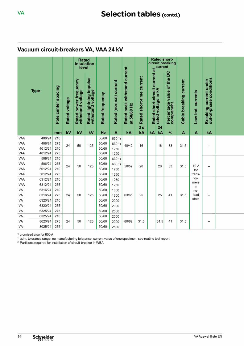
Vacuum circuit-breakers VA, VAA 24 kV
*) promised also for 800 A1) adm. tolerance range, no manufacturing tolerance, current value of one specimen, see routine test report2) Partitions required for installation of circuit-breaker in WBA
Selection tables (contd.)
Type
VAA
Pole
cen
ter s
paci
ng
406/24mm210
Rated insulation
levelR
ated
vol
tage
Rat
ed p
ower
freq
uenc
y w
ithst
and
volta
ge
kV
24
kV
50
Rat
ed li
ghtn
ing
impu
lse
with
stan
d vo
ltage
Rat
ed fr
eque
ncy
kV
125
Hz50/60
Rated short-circuit breaking
current
Rat
ed (n
orm
al) c
urre
nt
Rat
ed p
eak
with
stan
d cu
rren
tat
50/
60 H
zA
630 *)
kA
40/42R
ated
sho
rt-ti
me
curr
ent
3 s
Rat
ed s
hort
-circ
uit c
urre
nt a
tra
ted
volta
ge in
kV
kA
16
kA24
Perc
enta
ge v
alue
of t
he D
C
com
pone
nt
kA
16
%
33
Cab
le b
reak
ing
curr
ent
Low
ind.
cur
rent
s
A
31.5
A
10 A for
trans-for-
mers in
no-loadstate
Bre
akin
g cu
rren
t und
er
out-o
f-pha
se c
ondi
tions
kA
–VAAVAAVAAVAA
406/244012/24
275210
4012/24506/24
275210
VAAVAAVAAVAA
506/245012/24
275210
5012/246312/24
275210
24 50
50/6050/60
125
50/6050/60
24 50
50/6050/60
125
50/6050/60
630 *)12501250
630 *)
50/52 20 630 *)125012501250
63/65 25
20 33 31.5
25 41 31.5
–
–
VAAVAVAVA
6312/246316/24
275210
6316/246320/24
275210
VAVAVAVA
6320/246325/24
275275
6325/248020/24
210275
50/6050/6050/6050/60
24 50
50/6050/60
12550/6050/60
VA 8025/24 275 50/60
12501600160020002000250020002000 80/82 31.5 31.5 41 31.5
2500
–
Rated operating sequence
O -
3 m
in -
CO
- 3
min
- C
O
O -
0.3
s - C
O -
3 m
in -
CO
CO
- 15
s -
CO
Number of operating cycles without overhaulmechanical electrical
O -
0.3
s - C
O -
15 s
- C
O
Driv
e m
echa
nism
10000
Inte
rrup
ter c
ham
ber
with
rate
d (n
orm
al) c
urre
nt
30000 10000
Operating timeswith release
25 W 160 W 160 W
with
rate
d sh
ort-c
ircui
tcu
rren
t
Min
./Max
. op
enin
g tim
e
100
ms
45/65
Min
./Max
. op
enin
g tim
e
Min
./Max
. cl
osin
g tim
e 1)
ms
30/50
ms
35/65
Command timeswith release
25 W160 W160 W
Arc
dur
atio
n
OFF
ms
6 to 14
ms
50
OFF
ON
ms
–
ms
20
Cha
rgin
g tim
e fo
r m
otor
driv
e m
echa
nism
Part
ition
s
s
≤ 5
Wei
ght
kg
105
10000 30000 10000
10000 30000 10000
100 45/65 30/50 35/65
100 45/65 30/50 35/65
6 to 14 50 – 20
6 to 14 50 20 20
- 2)
≤ 5
- 2)
105-2)
≤ 5- 2)
105
10000 30000 10000 100 45/65 30/50 35/65 6 to 14 50 20 20
≤ 5≤ 9
- 2)
≤ 9≤ 12
105122122130
≤ 12≤ 12
-2)
≤ 12≤ 12 –
130130
130≤ 12

17VA Auswahlliste EN
VA
Type
VAA
Pole
cen
ter s
paci
ng
406/24mm210
Rated insulation
level
Rat
ed v
olta
ge
Rat
ed p
ower
freq
uenc
y w
ithst
and
volta
ge
kV
24
kV
50
Rat
ed li
ghtn
ing
impu
lse
with
stan
d vo
ltage
Rat
ed fr
eque
ncy
kV
125
Hz50/60
Rated short-circuit breaking
current
Rat
ed (n
orm
al) c
urre
nt
Rat
ed p
eak
with
stan
d cu
rren
tat
50/
60 H
z
A 630 *)
kA
40/42
Rat
ed s
hort
-tim
e cu
rren
t
3 s
Rat
ed s
hort
-circ
uit c
urre
nt a
tra
ted
volta
ge in
kV
kA
16
kA24
Perc
enta
ge v
alue
of t
he D
C
com
pone
nt
kA
16
%
33
Cab
le b
reak
ing
curr
ent
Low
ind.
cur
rent
s
A
31.5
A
10 A for
trans-for-
mers in
no-loadstate
Bre
akin
g cu
rren
t und
er
out-o
f-pha
se c
ondi
tions
kA
–VAAVAAVAAVAA
406/244012/24
275210
4012/24506/24
275210
VAAVAAVAAVAA
506/245012/24
275210
5012/246312/24
275210
24 50
50/6050/60
125
50/6050/60
24 50
50/6050/60
125
50/6050/60
630 *)12501250
630 *)
50/52 20 630 *)125012501250
63/65 25
20 33 31.5
25 41 31.5
–
–
VAAVAVAVA
6312/246316/24
275210
6316/246320/24
275210
VAVAVAVA
6320/246325/24
275275
6325/248020/24
210275
50/6050/6050/6050/60
24 50
50/6050/60
12550/6050/60
VA 8025/24 275 50/60
12501600160020002000250020002000 80/82 31.5 31.5 41 31.5
2500
–
Rated operating sequence
O -
3 m
in -
CO
- 3
min
- C
O
O -
0.3
s - C
O -
3 m
in -
CO
CO
- 15
s -
CO
Number of operating cycles without overhaulmechanical electrical
O -
0.3
s - C
O -
15 s
- C
O
Driv
e m
echa
nism
10000
Inte
rrup
ter c
ham
ber
with
rate
d (n
orm
al) c
urre
nt
30000 10000
Operating timeswith release
25 W 160 W 160 W
with
rate
d sh
ort-c
ircui
tcu
rren
t
Min
./Max
. op
enin
g tim
e
100
ms
45/65
Min
./Max
. op
enin
g tim
e
Min
./Max
. cl
osin
g tim
e 1)
ms
30/50
ms
35/65
Command timeswith release
25 W160 W160 W
Arc
dur
atio
n
OFF
ms
6 to 14
ms
50
OFF
ON
ms
–
ms
20
Cha
rgin
g tim
e fo
r m
otor
driv
e m
echa
nism
Part
ition
s
s
≤ 5
Wei
ght
kg
105
10000 30000 10000
10000 30000 10000
100 45/65 30/50 35/65
100 45/65 30/50 35/65
6 to 14 50 – 20
6 to 14 50 20 20
- 2)
≤ 5
- 2)
105-2)
≤ 5- 2)
105
10000 30000 10000 100 45/65 30/50 35/65 6 to 14 50 20 20
≤ 5≤ 9
- 2)
≤ 9≤ 12
105122122130
≤ 12≤ 12
-2)
≤ 12≤ 12 –
130130
130≤ 12
Selection tables (contd.)

18 VA Auswahlliste EN
VA
Vacuum circuit-breakers VA 36 kV
1) in case of class „minus 25 indoors“: extend closing time and opening time by 3 ms2) adm. tolerance range, no manufacturing tolerance, current value of one specimen, see routine test report3) at 60 Hz 2000 A only possible at max. ambient temperatures of 38 °C
Selection tables (contd.)
Type
VA
Pole
cen
ter s
paci
ng
6312/36mm275
Rated insulation
levelR
ated
vol
tage
Rat
ed p
ower
freq
uenc
y w
ithst
and
volta
ge
kV
36
kV
70
Rat
ed li
ghtn
ing
impu
lse
with
stan
d vo
ltage
Rat
ed fr
eque
ncy
kV
170
Hz50//60
Rated short-circuit
breaking current
Rat
ed (n
orm
al) c
urre
nt
Rat
ed p
eak
with
stan
d cu
rren
tat
50/
60 H
zA
1250
kA
65R
ated
sho
rt-ti
me
curr
ent
3 s
Rat
ed s
hort
-circ
uit c
urre
nt a
tra
ted
volta
ge in
kV
kA
25
kA36
Perc
enta
ge v
alue
of t
he D
C
com
pone
nt
kA
25
%
33
Cab
le b
reak
ing
curr
ent
Low
ind.
cur
rent
s
A
50
A
10 A for
trans-formers
in no-load
state
Bre
akin
g cu
rren
t und
er
out-o
f-pha
se c
ondi
tions
kA
6.3VAVAVAVA
6312/368012/36
400275
8012/368020/36
400275
VAVAVAVA
8020/368025/36
400400
10020/3610020/36
275400
36 70 170
50/6050/6050/6050/60
36 70
50/6050/60
17050/6050/60
12501250
821250
20003) 31.5
20002500
20003)
2000 104 40
31.5 40 50
40 40 50
6.3
6.3VA 10025/36 400 50/60 2500
Rated operating sequence
O -
3 m
in -
CO
- 3
min
- C
O
O -
0.3
s - C
O -
3 m
in -
CO
CO
- 15
s -
CO
Number of operatingcycles without overhaulmechanical electrical
O -
0.3
s - C
O -
15 s
- C
O
Driv
e m
echa
nism
10000
Inte
rrup
ter c
ham
ber
Rat
ed (n
orm
al) c
urre
nt
30000 10000
Operating timeswith release
25 W 160 W 160 W
with
rate
d sh
ort-c
ircui
t cur
rent
Min
. Max
. ope
ning
tim
e 2)
100
ms
45/65
Min
. Max
. ope
ning
tim
e 2)
Min
. Max
. clo
sing
tim
e 2)
ms
–
ms
40/70
Command timeswith release
25 W 160 W 160 W
Arc
dur
atio
n
OFF
ms
8 to 14
ms
50
OFF
ON
ms
20
ms
20
Cha
rgin
g tim
e fo
r mot
or d
rive
mec
hani
sm
Part
ition
s
s
≤ 9
Wei
ght
kg
10000 30000 10000
10000 30000 10000
100 45/65 31/45 40/70
100 45/65 31/45 40/70
8 to 14 50 20 20
8 to 14 50 20 20
≤ 12
–
–
–
≤ 12 –
on d
eman
d

19VA Auswahlliste EN
VA
Type
VA
Pole
cen
ter s
paci
ng
6312/36mm275
Rated insulation
level
Rat
ed v
olta
ge
Rat
ed p
ower
freq
uenc
y w
ithst
and
volta
ge
kV
36
kV
70
Rat
ed li
ghtn
ing
impu
lse
with
stan
d vo
ltage
Rat
ed fr
eque
ncy
kV
170
Hz50//60
Rated short-circuit
breaking current
Rat
ed (n
orm
al) c
urre
nt
Rat
ed p
eak
with
stan
d cu
rren
tat
50/
60 H
z
A1250
kA
65
Rat
ed s
hort
-tim
e cu
rren
t
3 s
Rat
ed s
hort
-circ
uit c
urre
nt a
tra
ted
volta
ge in
kV
kA
25
kA36
Perc
enta
ge v
alue
of t
he D
C
com
pone
nt
kA
25
%
33
Cab
le b
reak
ing
curr
ent
Low
ind.
cur
rent
s
A
50
A
10 A for
trans-formers
in no-load
state
Bre
akin
g cu
rren
t und
er
out-o
f-pha
se c
ondi
tions
kA
6.3VAVAVAVA
6312/368012/36
400275
8012/368020/36
400275
VAVAVAVA
8020/368025/36
400400
10020/3610020/36
275400
36 70 170
50/6050/6050/6050/60
36 70
50/6050/60
17050/6050/60
12501250
821250
20003) 31.5
20002500
20003)
2000 104 40
31.5 40 50
40 40 50
6.3
6.3VA 10025/36 400 50/60 2500
Rated operating sequence
O -
3 m
in -
CO
- 3
min
- C
O
O -
0.3
s - C
O -
3 m
in -
CO
CO
- 15
s -
CO
Number of operatingcycles without overhaulmechanical electrical
O -
0.3
s - C
O -
15 s
- C
O
Driv
e m
echa
nism
10000
Inte
rrup
ter c
ham
ber
Rat
ed (n
orm
al) c
urre
nt
30000 10000
Operating timeswith release
25 W 160 W 160 W
with
rate
d sh
ort-c
ircui
t cur
rent
Min
. Max
. ope
ning
tim
e 2)
100
ms
45/65
Min
. Max
. ope
ning
tim
e 2)
Min
. Max
. clo
sing
tim
e 2)
ms
–
ms
40/70
Command timeswith release
25 W 160 W 160 W
Arc
dur
atio
n
OFF
ms
8 to 14
ms
50
OFF
ON
ms
20
ms
20
Cha
rgin
g tim
e fo
r mot
or d
rive
mec
hani
sm
Part
ition
s
s
≤ 9
Wei
ght
kg
10000 30000 10000
10000 30000 10000
100 45/65 31/45 40/70
100 45/65 31/45 40/70
8 to 14 50 20 20
8 to 14 50 20 20
≤ 12
–
–
–
≤ 12 –
on d
eman
d
Selection tables (contd.)
20 VA Auswahlliste EN
VA
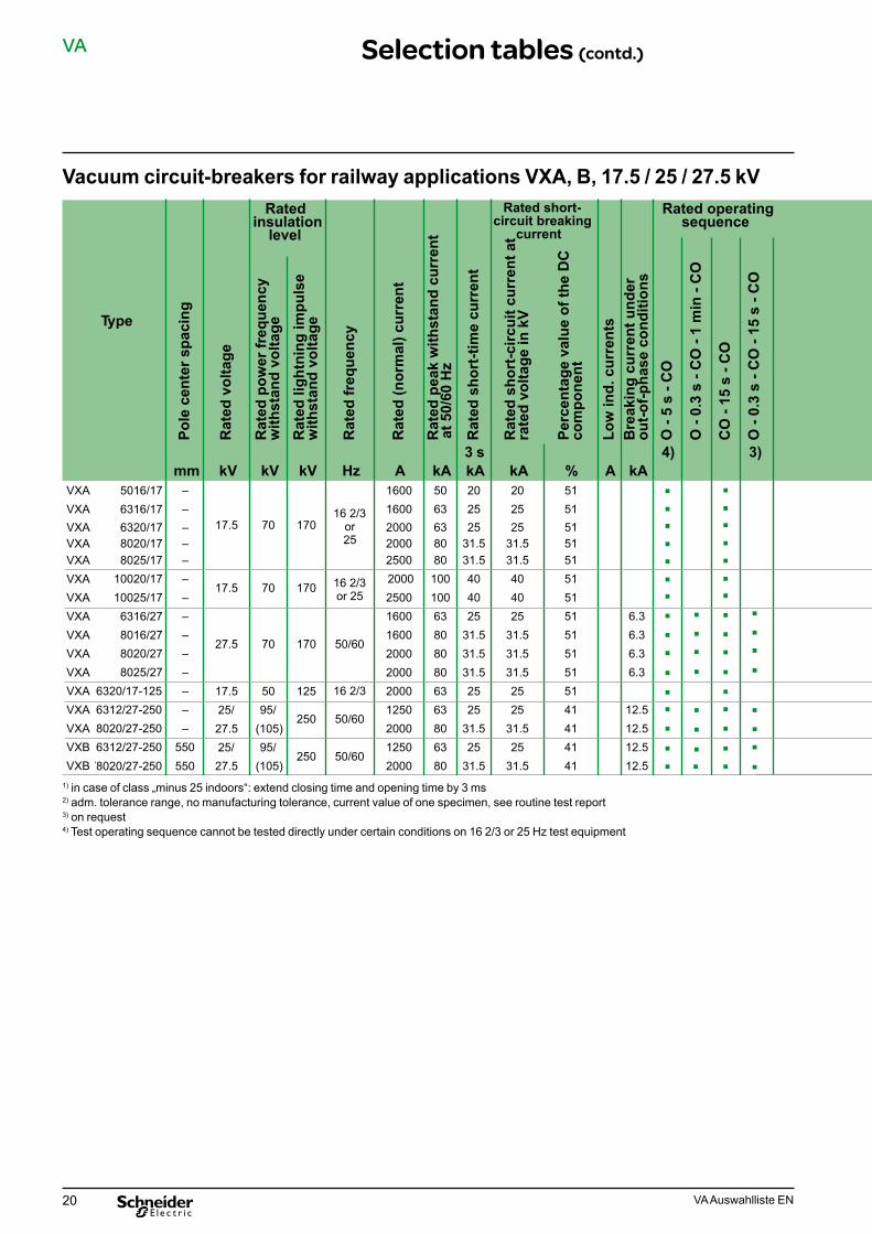
Vacuum circuit-breakers for railway applications VXA, B, 17.5 / 25 / 27.5 kV
1) in case of class „minus 25 indoors“: extend closing time and opening time by 3 ms2) adm. tolerance range, no manufacturing tolerance, current value of one specimen, see routine test report3) on request4) Test operating sequence cannot be tested directly under certain conditions on 16 2/3 or 25 Hz test equipment
Selection tables (contd.)
Type
VXA
Pole
cen
ter s
paci
ng
5016/17mm
–
Rated insulation
levelR
ated
vol
tage
Rat
ed p
ower
freq
uenc
y w
ithst
and
volta
ge
kV
17.5
kV
70
Rat
ed li
ghtn
ing
impu
lse
with
stan
d vo
ltage
Rat
ed fr
eque
ncy
kV
170
Hz
16 2/3or25
Rated short-circuit breaking
current
Rat
ed (n
orm
al) c
urre
nt
Rat
ed p
eak
with
stan
d cu
rren
t a
t 50/
60 H
z
A1600
kA50
Rat
ed s
hort
-tim
e cu
rren
t3 s
Rat
ed s
hort
-circ
uit c
urre
nt a
tra
ted
volta
ge in
kV
kA20
kA20
sequence
Perc
enta
ge v
alue
of t
he D
C
com
pone
nt
Low
ind.
cur
rent
s
%51
A
Bre
akin
g cu
rren
t und
er
out-o
f-pha
se c
ondi
tions
O -
5 s
- CO
4)kA
O -
0.3
s - C
O -
1 m
in -
CO
CO
- 15
s -
CO
O -
0.3
s - C
O -
15 s
- C
O
3)
VXAVXAVXAVXA
6316/176320/17
––
8020/178025/17
––
VXAVXAVXAVXA
10020/1710025/17
––
6316/278016/27
––
17.5 70
27.5 70
170 16 2/3or 25
170 50/60
16002000
6363
20002500
8080
2525
2525
31.531.5
31.531.5
2000 2500
100100
16001600
6380
4040
4040
2531.5
2531.5
5151515151515151
6.36.3
VXAVXAVXAVXA
8020/278025/27
––
6320/17-1256312/27-250
––
VXAVXBVXB
8020/27-2506312/27-250
–550
78020/27-250 550
17.525/
5095/
125
250
16 2/3
50/6027.525/
(105)95/
27.5 (105)250 50/60
20002000
8080
20001250
6363
31.531.5
31.531.5
2525
2525
20001250
8063
2000 80
31.525
31.525
31.5 31.5
51515141
6.36.3
12.5414141
12.512.512.5
Number of operating cycles without overhaul
mechanical
Driv
e m
echa
nism
10000
electrical
Inte
rrup
ter c
ham
ber
with
rate
d (n
orm
al) c
urre
nt
30000 10000
Operating timesinstantaneous trippin
with without
with
rate
d sh
ort-c
ircui
t cur
ent
Ope
ning
tim
e 2)
100
ms
10 to 17
Ope
ning
tim
e 2)
Clo
sing
tim
e 2)
ms
20 to 40
ms
40 to 55
Command timesinstantaneous trippi
with
Ope
ning
tim
e w
ithou
t in
stan
tane
ous
trip
ping
Ope
ning
tim
e w
ith in
stan
ta-
neou
s tr
ippi
ng
ms
15 to 82 25 to 105
OFF
OFF
ms
5
ms
20
ON
Cha
rgin
g tim
e fo
r mot
or d
ri-ve
mec
hani
sm
ms
20
s
≤ 12
Part
ition
s
Wei
ght
kg
10000
10000
30000 10000
30000 10000
50
50 10 to 17
100 –
20 to 40 40 to 55
20 to 40 40 to 55
10 to 82 25 to 105
– 25 to 58
5 20
–
2020
20 ≤ 12
2020
≤ 12≤ 12
20000
10000
30000
30000
20000
10000
10000 30000 10000
100
100
––
20 to 40
30 to 45
40 to 55
40 to 55
100
–––
30 to 45 40 to 55
––
25 to 105
35 to 58
2020
––
2020
––
35 to 58–
––
2020
– 20
2020
≤ 12≤ 12
2020
≤ 12≤ 12
2020
≤ 12≤ 12
20 ≤ 12
on d
eman
d
Rated operating
without

21VA Auswahlliste EN
VA
Type
VXA
Pole
cen
ter s
paci
ng
5016/17mm
–
Rated insulation
level
Rat
ed v
olta
ge
Rat
ed p
ower
freq
uenc
y w
ithst
and
volta
ge
kV
17.5
kV
70
Rat
ed li
ghtn
ing
impu
lse
with
stan
d vo
ltage
Rat
ed fr
eque
ncy
kV
170
Hz
16 2/3or25
Rated short-circuit breaking
current
Rat
ed (n
orm
al) c
urre
nt
Rat
ed p
eak
with
stan
d cu
rren
t a
t 50/
60 H
z
A1600
kA50
Rat
ed s
hort
-tim
e cu
rren
t
3 s
Rat
ed s
hort
-circ
uit c
urre
nt a
tra
ted
volta
ge in
kV
kA20
kA20
sequence
Perc
enta
ge v
alue
of t
he D
C
com
pone
nt
Low
ind.
cur
rent
s
%51
A
Bre
akin
g cu
rren
t und
er
out-o
f-pha
se c
ondi
tions
O -
5 s
- CO
4)kA
O -
0.3
s - C
O -
1 m
in -
CO
CO
- 15
s -
CO
O -
0.3
s - C
O -
15 s
- C
O
3)
VXAVXAVXAVXA
6316/176320/17
––
8020/178025/17
––
VXAVXAVXAVXA
10020/1710025/17
––
6316/278016/27
––
17.5 70
27.5 70
170 16 2/3or 25
170 50/60
16002000
6363
20002500
8080
2525
2525
31.531.5
31.531.5
2000 2500
100100
16001600
6380
4040
4040
2531.5
2531.5
5151515151515151
6.36.3
VXAVXAVXAVXA
8020/278025/27
––
6320/17-1256312/27-250
––
VXAVXBVXB
8020/27-2506312/27-250
–550
78020/27-250 550
17.525/
5095/
125
250
16 2/3
50/6027.525/
(105)95/
27.5 (105)250 50/60
20002000
8080
20001250
6363
31.531.5
31.531.5
2525
2525
20001250
8063
2000 80
31.525
31.525
31.5 31.5
51515141
6.36.3
12.5414141
12.512.512.5
Number of operating cycles without overhaul
mechanical
Driv
e m
echa
nism
10000
electrical
Inte
rrup
ter c
ham
ber
with
rate
d (n
orm
al) c
urre
nt
30000 10000
Operating timesinstantaneous trippin
with without
with
rate
d sh
ort-c
ircui
t cur
ent
Ope
ning
tim
e 2)
100
ms
10 to 17
Ope
ning
tim
e 2)
Clo
sing
tim
e 2)
ms
20 to 40
ms
40 to 55
Command timesinstantaneous trippi
with
Ope
ning
tim
e w
ithou
t in
stan
tane
ous
trip
ping
Ope
ning
tim
e w
ith in
stan
ta-
neou
s tr
ippi
ng
ms
15 to 82 25 to 105
OFF
OFF
ms
5
ms
20
ON
Cha
rgin
g tim
e fo
r mot
or d
ri-ve
mec
hani
sm
ms
20
s
≤ 12
Part
ition
s
Wei
ght
kg
10000
10000
30000 10000
30000 10000
50
50 10 to 17
100 –
20 to 40 40 to 55
20 to 40 40 to 55
10 to 82 25 to 105
– 25 to 58
5 20
–
2020
20 ≤ 12
2020
≤ 12≤ 12
20000
10000
30000
30000
20000
10000
10000 30000 10000
100
100
––
20 to 40
30 to 45
40 to 55
40 to 55
100
–––
30 to 45 40 to 55
––
25 to 105
35 to 58
2020
––
2020
––
35 to 58–
––
2020
– 20
2020
≤ 12≤ 12
2020
≤ 12≤ 12
2020
≤ 12≤ 12
20 ≤ 12on
dem
and
Rated operating
without
Selection tables (contd.)

22 VA Auswahlliste EN
VA
Vacuum circuit-breakers for high numbers of switching operations VXC, 24 / 36 / 38 kV
1) in case of class „minus 25 indoors“: extend closing time and opening time by 3 ms2) adm. tolerance range, no manufacturing tolerance, current value of one specimen, see routine test report
Selection tables (contd.)
Type
VXC
Pole
cen
ter s
paci
ng
6312/24mm210
Insulatinglevel
Rat
ed v
olta
ge
Rat
ed p
ower
freq
uenc
y w
ithst
and
volta
ge
kV
24
kV
50
Rat
ed li
ghtn
ing
impu
lse
with
stan
d vo
ltage
Rat
ed fr
eque
ncy
kV
125
Hz
50/60
Rated short-circuit
breaking current
Rat
ed (n
orm
al) c
urre
nt
Rat
ed p
eak
with
stan
d cu
rren
t
A1250
kA
63/65
Rat
ed s
hort
-tim
e cu
rren
t
3 s Rat
ed s
hort-
circ
uit c
urre
nt a
t ra
ted
volta
ge in
kV
kA
25
kA
25
Rated transient
recovery voltage
Perc
enta
ge v
alue
of t
he D
C
com
pone
nt
Peak
val
ue (f
irst-p
ole-
to-
clea
r fac
tor 1
.5)
%
40
kA
–
at ra
ted
volta
ge in
kV
Uc
Rat
e of
rise
kV41
kV/µs
0.47
Rat
ed c
able
-cha
rgin
g br
eaki
ng c
urre
ntLo
w in
d. c
urre
nts
A
31.5
A
Bre
akin
g cu
rren
t und
er
out-o
f-pha
se c
ondi
tions
kA6.3
VXCVXCVXCVXC
6312/246325/24
275275
6312/366312/36
275400
VXCVXCVXCVXC
6325/368012/36
400275
8012/368025/36
400400
36 70 170 50/60
1250250012501250 63/65
2525
2525
25001250
80/8212502500
2531.5
2531.5
31.531.5
31.531.5
40 –
41416262
0.5762626262
–
50 –
6.36.36.36.36.37.97.97.9
VXCVXCVXCVXC
6312/38-2006325/38-200
400400
8012/38-2008025/38-200
400400
VXCVXC
10012/38-20010025/38-200
400400
38 95 200 50/60
12502500
63/6563/65
12502500
80/8280/82
2525
2525
31.531.5
31.531.5
12502500
100/104100/104
4040
4040
40 –
71.771.7
1.3271.771.771.771.7
50 –
6.36.37.97.9––
Rated operatingsequence
O -
3 m
in -
CO
- 3
min
- C
O
O -
0.3
s - C
O -
3 m
in -
CO
CO
- 15
s -
CO
Switching operationswithout inspection
mechanical electrical
O -
0.3
s - C
O -
15 s
- C
O
Driv
e
25000
Inte
rrup
ter c
ham
ber
with
rate
d (n
orm
al) c
urre
nt
30000 25000
25 W 160 W 160 W
with
rate
d sh
ort-c
ircui
t cu
rren
t
Ope
ning
tim
e 2)
100
ms
45-65
Ope
ning
tim
e 2)
Clo
sing
tim
e 2)
ms
31-45
ms
40-70
Command timswith release
25 W160 W 160 W
OFF
OFF
ms
50
ms
20
ON
Cha
rgin
g tim
e fo
r mot
or
driv
e m
echa
nism
ms
20
s
≤ 12
Tren
nwPa
rtiti
onsä
nde
Wei
ght
kg122
25000 30000 25000 100 45-65 31-45 40-70 50 20 20 ≤ 12
– 140140
–130160160130
– 160160
25000 30000 25000 100 45-65 31-45 40-70 50 20 20 ≤ 12
160160160160160160
Operating timeswith release
■■
■
■
■
■
■
■
■
■■
■
■
■ ■ ■
■ ■ ■ ■
■ ■ ■ ■
23VA Auswahlliste EN
VA
Type
VXC
Pole
cen
ter s
paci
ng
6312/24mm210
Insulatinglevel
Rat
ed v
olta
ge
Rat
ed p
ower
freq
uenc
y w
ithst
and
volta
ge
kV
24
kV
50
Rat
ed li
ghtn
ing
impu
lse
with
stan
d vo
ltage
Rat
ed fr
eque
ncy
kV
125
Hz
50/60
Rated short-circuit
breaking current
Rat
ed (n
orm
al) c
urre
nt
Rat
ed p
eak
with
stan
d cu
rren
t
A1250
kA
63/65
Rat
ed s
hort
-tim
e cu
rren
t
3 s Rat
ed s
hort-
circ
uit c
urre
nt a
t ra
ted
volta
ge in
kV
kA
25
kA
25
Rated transient
recovery voltage
Perc
enta
ge v
alue
of t
he D
C
com
pone
nt
Peak
val
ue (f
irst-p
ole-
to-
clea
r fac
tor 1
.5)
%
40
kA
–
at ra
ted
volta
ge in
kV
Uc
Rat
e of
rise
kV41
kV/µs
0.47
Rat
ed c
able
-cha
rgin
g br
eaki
ng c
urre
ntLo
w in
d. c
urre
nts
A
31.5
A
Bre
akin
g cu
rren
t und
er
out-o
f-pha
se c
ondi
tions
kA6.3
VXCVXCVXCVXC
6312/246325/24
275275
6312/366312/36
275400
VXCVXCVXCVXC
6325/368012/36
400275
8012/368025/36
400400
36 70 170 50/60
1250250012501250 63/65
2525
2525
25001250
80/8212502500
2531.5
2531.5
31.531.5
31.531.5
40 –
41416262
0.5762626262
–
50 –
6.36.36.36.36.37.97.97.9
VXCVXCVXCVXC
6312/38-2006325/38-200
400400
8012/38-2008025/38-200
400400
VXCVXC
10012/38-20010025/38-200
400400
38 95 200 50/60
12502500
63/6563/65
12502500
80/8280/82
2525
2525
31.531.5
31.531.5
12502500
100/104100/104
4040
4040
40 –
71.771.7
1.3271.771.771.771.7
50 –
6.36.37.97.9––
Rated operatingsequence
O -
3 m
in -
CO
- 3
min
- C
O
O -
0.3
s - C
O -
3 m
in -
CO
CO
- 15
s -
CO
Switching operationswithout inspection
mechanical electrical
O -
0.3
s - C
O -
15 s
- C
O
Driv
e
25000
Inte
rrup
ter c
ham
ber
with
rate
d (n
orm
al) c
urre
nt
30000 25000
25 W 160 W 160 W
with
rate
d sh
ort-c
ircui
t cu
rren
t
Ope
ning
tim
e 2)
100
ms
45-65
Ope
ning
tim
e 2)
Clo
sing
tim
e 2)
ms
31-45
ms
40-70
Command timswith release
25 W160 W 160 W
OFF
OFF
ms
50
ms
20
ON
Cha
rgin
g tim
e fo
r mot
or
driv
e m
echa
nism
ms
20
s
≤ 12
Tren
nwPa
rtiti
onsä
nde
Wei
ght
kg122
25000 30000 25000 100 45-65 31-45 40-70 50 20 20 ≤ 12
– 140140
–130160160130
– 160160
25000 30000 25000 100 45-65 31-45 40-70 50 20 20 ≤ 12
160160160160160160
Operating timeswith release
■■
■
■
■
■
■
■
■
■■
■
■
■ ■ ■
■ ■ ■ ■
■ ■ ■ ■
Selection tables (contd.)

24 VA Auswahlliste EN
VA
High-capacity vacuum circuit-breakers for high currents VAH 12 kV, 13.8 kV (15.8), 17.5 kV
*) with motor-actuated fans**) checked in accordance with generator current ANSI C37.0131) adm. tolerance range, no manufacturing tolerance, current value of one specimen, see routine test report2) max. ambient temperature 38 °C (4900 A at 40°C), terminal bars ≥ 4000 mm2 Cu3) max. ambient temperature 39 °C (7950 A at 40°C), terminal bars ≥ 8000 mm2 Cu4) Terminal bars ≥ 4000 mm2 Cu5) Terminal bars ≥ 8000 mm2 Cu
Selection tables (contd.)
■
■
■
■ ■
■ ■
■
■■
■
■
■
■
■
■
■
■
■
■■
■
■
■
■
■■
■
■
■
■
■
■
■
■
■
Type
VAH
Pole
cen
ter s
paci
ng
12-50-40-27 **)mm275
Rated insulation
levelR
ated
vol
tage
Rat
ed p
ower
freq
uenc
yw
ithst
and
volta
ge
kV kV
Rat
ed li
ghtn
ing
impu
lse
with
stan
d vo
ltage
Rat
ed fr
eque
ncy
kV Hz50/60
Rated short-circuit
breaking current
Rat
ed (n
orm
al) c
urre
nt
Rat
ed p
eak
with
stan
d cu
rren
t at 5
0/60
Hz
A4000
kA
125
Rat
ed s
hort
-tim
e cu
rren
t3 s
Rat
ed s
hort
-circ
uit c
urre
nt
at ra
ted
volta
ge in
kV
kA
50
kA
50
Rated transient recovery voltage
Perc
enta
ge v
alue
of t
he D
Cco
mpo
nent
Peak
val
ue (f
irst-p
ole-
to-
clea
r fac
tor 1
.5) a
t rat
edVo
ltage
%
50
kV
20.6
Rat
e of
rise
Cab
le b
reak
ing
curr
ent
kV/µs
0.34
A
25
Low
ind.
cur
rent
s
Bre
akin
g cu
rren
t und
erou
t-of-p
hase
con
ditio
ns
A
on re-
quest
kA
VAHVAHVAHVAH
12-50-50-27 **)12-50-50-27 **)
275275
12-63-12-2712-63-25-27
275275
VAHVAHVAHVAH
12-63-31-2712-63-40-27
275275
12-63-50-2712-63-50-27
275275
50605050
12 28(42)
75 5050/60
5060
5000 2)
4750 4)
12502500
160 63
6331504000
5000 2)
4750 4)63
also possible
15 23.7
15 20.6
4.0
0.34
2515 20.6 0.34
VAHVAHVAHVAH
12-63-80-27 *)12-63-80-27 *)
275275
13,8-63-12-2713,8-63-25-27
275275
VAHVAHVAHVAH
13,8-63-31-2713,8-63-40-27
275275
13,8-63-50-2713,8-63-50-27
275275
50605050
13.8 38(15.8) (42)
9550505060
VAHVAHVAHVAH
13,8-63-80-27 *)13.8-63-80-27 *)
275275
17,5-50-12-27 **)17,5-50-25-27 **)
275275
VAHVAHVAHVAH
17,5-50-31-27 **)17,5-50-31-27 **)
275275
17,5-50-40-27 **)17,5-50-50-27 **)
275275
5060
50/6050/60
17.5 38(42)
955060
50/6050
8000 3)
7700 5)
12502500
160
50
63
6331504000
5000 2)
4750 4)
63
also possible
15 23.7
15 23.7(27.1)
4.0
0.39(0.40)
31.515 23.7
(27.1)0.39(0.40)
8000 3)
7700 5)
12502500
125
50 on13.8 kV
50 50
315030004000
5000 2)
15 27.1
15 30
4.0
0.42 31.5
VAHVAHVAH
17,5-50-50-27 **)17,5-50-80-27*)**)
275275
17,5-50-80-27*)**) 275
605060
4750 4)
8000 3)
7700 5)
Rated operat-ing sequence
O -
3 m
in -
CO
- 3
min
- C
OO
- 0.
3 s
- CO
- 3
min
- C
OC
O -
15 s
- C
O
Switching operationswithout inspection
mechanical electrical
O -
0.3
s - C
O -
15 s
- C
O
Driv
e
10000
Inte
rrup
ter c
ham
ber
with
rate
d (n
orm
al) c
urre
nt
10000 10000
Operating timeswith release
25 W
with
rate
d sh
ort-c
ircui
t cu
rren
t
Ope
ning
tim
e 1)
30
ms
70 to 110
Ope
ning
tim
e 1)
Clo
sing
tim
e 1)
ms
–
ms
35 to 55
Command timeswith release
25 W160 W160 W160 W 160 W
Arc
dur
atio
n
Non
-sim
ulta
neity
(bet
wee
n po
les)
ms
6 to 12
ms
≤ 2
OFF
OFF
ms
50
ms
–
ON
Cha
rgin
g tim
e fo
r mot
ordr
ive
mec
hani
sm
ms
20
s
≤ 12
Part
ition
s
Wei
ght
kg500
10000 10000 10000 20 70 to 110 – 35 to 55 6 to 12 ≤ 2 50 – 20 ≤ 12
500500200200380500500500
10000 10000 10000
10000 10000 10000
20 70 to 110 – 35 to 55 6 to 12 ≤ 2 50 –
30 70 to 110 – 35 to 55 6 to 14 ≤ 2 50 –
20 ≤ 12
500500200200380500500500
20 ≤ 12
500500200200200380500500500500500

25VA Auswahlliste EN
VA
■
■
■
■ ■
■ ■
■
■■
■
■
■
■
■
■
■
■
■
■■
■
■
■
■
■■
■
■
■
■
■
■
■
■
■
Type
VAH
Pole
cen
ter s
paci
ng
12-50-40-27 **)mm275
Rated insulation
level
Rat
ed v
olta
ge
Rat
ed p
ower
freq
uenc
yw
ithst
and
volta
ge
kV kV
Rat
ed li
ghtn
ing
impu
lse
with
stan
d vo
ltage
Rat
ed fr
eque
ncy
kV Hz50/60
Rated short-circuit
breaking current
Rat
ed (n
orm
al) c
urre
nt
Rat
ed p
eak
with
stan
d cu
rren
t at 5
0/60
Hz
A4000
kA
125
Rat
ed s
hort
-tim
e cu
rren
t
3 s
Rat
ed s
hort
-circ
uit c
urre
nt
at ra
ted
volta
ge in
kV
kA
50
kA
50
Rated transient recovery voltage
Perc
enta
ge v
alue
of t
he D
Cco
mpo
nent
Peak
val
ue (f
irst-p
ole-
to-
clea
r fac
tor 1
.5) a
t rat
edVo
ltage
%
50
kV
20.6
Rat
e of
rise
Cab
le b
reak
ing
curr
ent
kV/µs
0.34
A
25
Low
ind.
cur
rent
s
Bre
akin
g cu
rren
t und
erou
t-of-p
hase
con
ditio
ns
A
on re-
quest
kA
VAHVAHVAHVAH
12-50-50-27 **)12-50-50-27 **)
275275
12-63-12-2712-63-25-27
275275
VAHVAHVAHVAH
12-63-31-2712-63-40-27
275275
12-63-50-2712-63-50-27
275275
50605050
12 28(42)
75 5050/60
5060
5000 2)
4750 4)
12502500
160 63
6331504000
5000 2)
4750 4)63
also possible
15 23.7
15 20.6
4.0
0.34
2515 20.6 0.34
VAHVAHVAHVAH
12-63-80-27 *)12-63-80-27 *)
275275
13,8-63-12-2713,8-63-25-27
275275
VAHVAHVAHVAH
13,8-63-31-2713,8-63-40-27
275275
13,8-63-50-2713,8-63-50-27
275275
50605050
13.8 38(15.8) (42)
9550505060
VAHVAHVAHVAH
13,8-63-80-27 *)13.8-63-80-27 *)
275275
17,5-50-12-27 **)17,5-50-25-27 **)
275275
VAHVAHVAHVAH
17,5-50-31-27 **)17,5-50-31-27 **)
275275
17,5-50-40-27 **)17,5-50-50-27 **)
275275
5060
50/6050/60
17.5 38(42)
955060
50/6050
8000 3)
7700 5)
12502500
160
50
63
6331504000
5000 2)
4750 4)
63
also possible
15 23.7
15 23.7(27.1)
4.0
0.39(0.40)
31.515 23.7
(27.1)0.39(0.40)
8000 3)
7700 5)
12502500
125
50 on13.8 kV
50 50
315030004000
5000 2)
15 27.1
15 30
4.0
0.42 31.5
VAHVAHVAH
17,5-50-50-27 **)17,5-50-80-27*)**)
275275
17,5-50-80-27*)**) 275
605060
4750 4)
8000 3)
7700 5)
Rated operat-ing sequence
O -
3 m
in -
CO
- 3
min
- C
OO
- 0.
3 s
- CO
- 3
min
- C
OC
O -
15 s
- C
O
Switching operationswithout inspection
mechanical electrical
O -
0.3
s - C
O -
15 s
- C
O
Driv
e
10000
Inte
rrup
ter c
ham
ber
with
rate
d (n
orm
al) c
urre
nt
10000 10000
Operating timeswith release
25 W
with
rate
d sh
ort-c
ircui
t cu
rren
t
Ope
ning
tim
e 1)
30
ms
70 to 110
Ope
ning
tim
e 1)
Clo
sing
tim
e 1)
ms
–
ms
35 to 55
Command timeswith release
25 W160 W160 W160 W 160 W
Arc
dur
atio
n
Non
-sim
ulta
neity
(bet
wee
n po
les)
ms
6 to 12
ms
≤ 2
OFF
OFF
ms
50
ms
–
ON
Cha
rgin
g tim
e fo
r mot
ordr
ive
mec
hani
sm
ms
20
s
≤ 12
Part
ition
s
Wei
ght
kg500
10000 10000 10000 20 70 to 110 – 35 to 55 6 to 12 ≤ 2 50 – 20 ≤ 12
500500200200380500500500
10000 10000 10000
10000 10000 10000
20 70 to 110 – 35 to 55 6 to 12 ≤ 2 50 –
30 70 to 110 – 35 to 55 6 to 14 ≤ 2 50 –
20 ≤ 12
500500200200380500500500
20 ≤ 12
500500200200200380500500500500500
Selection tables (contd.)

26 VA Auswahlliste EN
VA Electric circuit diagrams
Vacuum circuit-breakers without reclosing facility (Auto-Reclosure) Basic designThis circuit diagram shows the max. possible secondary equipment. Depending on the order volume, components shown may not be included.with terminal strip with anti-pumping relay
Devices which may be installed in the circuit-breaker depending on order specificationF 11 Shunt opening release (shunt release)F 2 Shunt closing release (shunt release)M 1 Motor to charge the energy-storing deviceS 1 Auxiliary switchS 21–S 25 Push switch actuated by energy storing deviceS 41 Push switch actuated by the buttons ON / OFFS 43 Push button actuated by the button OFFS 6 Push-button actuated by the switchgear truckV 1 DiodeV 2 RectifierX 1 Terminal strip
Charging the energy-storingdeviceAs the switch (F 101) is closed, the motor (M) is energized and the energy-storing device is charged. Once charging is finished, the push switches (S 22 and S 23) are actuated by a shaft, and the motor switchedoff.
Switching ON (Closing)Closing can be effected
■ mechanically via the button „ON“ ■ electrically via the contact element „ON“ (SOE), which excites the shunt closing release (F 2).
As soon as closing operation (ON) is terminated, the motor charges the energy-storing device, as the push switches (S 22 and S 23) are closed with the energy-storing device discharged.
Switching OFF (Opening)Opening can be effected
■ mechanically via the button „OFF“ ■ electrically via the contact element „OFF“ (SOA), which excites the shunt opening release (F 11). ■ electrically via an overcurrent relay (F 321) which excites the shunt opening release (F 11).
MessageIn closed state („ON“), the pilot lamp „ON“ (HOE) is lit, in open state („OFF“), the pilot lamp „OFF“ (HOA) is lit. The „malfunction“ signalling relay (KOS) only receives a switching pulse via the passing contact (239/230) from the auxiliary switch of the circuit-breaker (S 1) if tripping is effected by the overcurrent relay (F 321), as in case of manual operation, either the NC contact of the push switch (S 41) of the button„ OFF“ opens, or, in case of electrical operation, the NC contact of the contact element „OFF“ (SOA).The „malfunction“ signalling relay features a self-holding contact, but can be de-excited via its shut-down element (SOR). The „malfunction“ pilot lamp (HOS) is energized via the „malfunction“ signalling relay.
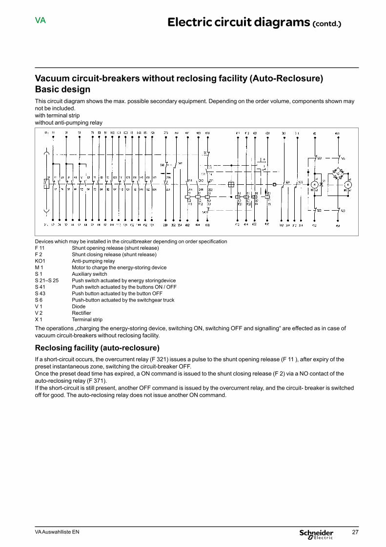
27VA Auswahlliste EN
VA Electric circuit diagrams (contd.)
Vacuum circuit-breakers without reclosing facility (Auto-Reclosure) Basic designThis circuit diagram shows the max. possible secondary equipment. Depending on the order volume, components shown may not be included.with terminal strip without anti-pumping relay
Devices which may be installed in the circuitbreaker depending on order specificationF 11 Shunt opening release (shunt release)F 2 Shunt closing release (shunt release)KO1 Anti-pumping relayM 1 Motor to charge the energy-storing deviceS 1 Auxiliary switchS 21–S 25 Push switch actuated by energy storingdeviceS 41 Push switch actuated by the buttons ON / OFFS 43 Push button actuated by the button OFFS 6 Push-button actuated by the switchgear truckV 1 DiodeV 2 RectifierX 1 Terminal strip
The operations „charging the energy-storing device, switching ON, switching OFF and signalling“ are effected as in case of vacuum circuit-breakers without reclosing facility.
Reclosing facility (auto-reclosure)If a short-circuit occurs, the overcurrent relay (F 321) issues a pulse to the shunt opening release (F 11 ), after expiry of the preset instantaneous zone, switching the circuit-breaker OFF.Once the preset dead time has expired, a ON command is issued to the shunt closing release (F 2) via a NO contact of the auto-reclosing relay (F 371).If the short-circuit is still present, another OFF command is issued by the overcurrent relay, and the circuit- breaker is switched off for good. The auto-reclosing relay does not issue another ON command.

28 VA Auswahlliste EN
VA Electric circuit diagrams (contd.)
Electric circuit diagrams for circuit-breakersThis circuit diagram shows the max. possible secondary equipment. Depending on the order volume, components shown may not be included.with connector, 24-polewith anti-pumping relay
Devices which may be installed in the circuit-breaker depending on order specificationF 11 Shunt opening release (shunt release)F 2 Shunt closing release (shunt release)M 1 Motor to charge the energy-storing deviceS 1 Auxiliary switchS 21–S 25 Push switch actuated by energy storing deviceS 41 Push switch actuated by the buttons ON / OFFS 43 Push button actuated by the button OFFS 6 Push-button actuated by the switchgear truckV 1 DiodeV 2 RectifierX 1 Terminal strip
This circuit diagram shows the max. possible secondary equipment. Depending on the order volume, components shown may not be included.with connector, 24-polewithout anti-pumping relay

29VA Auswahlliste EN
VA Electric circuit diagrams (contd.)
Electric circuit diagrams for circuit-breakersThis circuit diagram shows the max. possible secondary equipment. Depending on the order volume, components shown may not be included.with connector, 64-polewith anti-pumping relay
Devices which may be installed in the circuit-breaker depending on order specificationF 11 Shunt opening release (shunt release)F 2 Shunt closing release (shunt release)M 1 Motor to charge the energy-storing deviceS 1 Auxiliary switchS 21–S 25 Push switch actuated by energy storing deviceS 41 Push switch actuated by the buttons ON / OFFS 43 Push button actuated by the button OFFS 6 Push-button actuated by the switchgear truckV 1 DiodeV 2 RectifierX 1 Terminal strip
This circuit diagram shows the max. possible secondary equipment. Depending on the order volume, components shown may not be included.with connector, 64-polewithout anti-pumping relay

30 VA Auswahlliste EN
VA Electric circuit diagrams (contd.)
Vacuum circuit-breaker VXA with instantaneous tripping 60 V DC
A1 Thyristor moduleA 3 Capacitor diode moduleC 1, 2,3, 4, 5 Surge discharge capacitor 1000 μF/100 VF 2 Shunt closing release ONF 4 Undervoltage releaseF 11 Shunt tripping release OFFF 12 EMERGENCY OFF auxiliary releaseF 31, 32 Secondary releaseK 2 Timing relay 1.5 secM 1 MotorR 1, 2 Charging resistor 39 ΩR 3 Charging resistor 68 ΩR 7 Protection resistor 68 ΩR 11, 12 Discharge resistor 56 ΩS 1 Auxiliary switchS 21–26 Push switch actuated by energy storing deviceS 41–43 Push switch, actuated by mechanical ON / OFF switchV 1, 3, 4, 5, 6 DiodeV 2 RectifierX 0 ConnectorX 1 T erminal strip in circuit-breaker
Charging the energy-storingdeviceThe motor (M) is energized via L+ and L-, the energy storing device is charged.Once charging is finished, the push switches (S 22 and S 23) are actuated by a shaft, and the motor switched off.
Switching ON (Closing) Closing can be effected
■ mechanically via the button „ON“ ■ electrically via the contact element „ON“, which excites the shunt closing release (F 2).
As soon as closing operation (ON) is terminated, the motor charges the energy-storing device, as the push switches (S 22 and S 23) are closedwith the energy-storing device discharged.
Switching OFF (Opening)Opening can be effected
■ mechanically via the button „OFF“ ■ electrically via the contact element „OFF“, which excitesthe shunt opening release (F 11). ■ electrically via the contact element „Emergency OFF“, which excites the shunt opening release (F 12).

31VA Auswahlliste EN
VA Electric circuit diagrams (contd.)
Vacuum circuit-breaker VXA with instantaneous tripping 220 V DC
A 1, 2 Thyristor moduleA 3 Capacitor diode moduleC 1, 2, 3, 4, 5 Surge discharge capacitor 1000 μF/100 VF 2 Shunt closing release ONF 4 Undervoltage releaseF 11 Shunt tripping release OFFF 12 EMERGENCY OFF auxiliary releaseF 31, 32 Secondary releaseK 1 Anti-pumping relayK 2, 3 Timing relay 1.5 secM 1 MotorR 1, 3, 5, 6 Charging resistor 39 ΩR 2, 4 Charging resistor 14 ΩR 7 Protection resistor 14 ΩR 8 Series resistor 68 ΩR 11, 12, 13 Discharge resistor 56 ΩS 1 Auxiliary switchS 21–26 Push switch actuated by energy storing deviceS 41–43 Push switch, actuated by mechanical ON / OFF switchV 1, 3, 4, 5, 6 DiodeV 2 RectifierX 0 ConnectorX 1 Terminal strip in circuit-breakerX 2 Terminal strip on truck
Charging the energy-storingdevice The motor (M) is energized via L+ and L-, the energy storing device is charged.Once charging is finished, the push switches (S 22 and S 23) are actuated by a shaft, and the motor switched off.
Switching ON (Closing)Closing can be effected
■ mechanically via the button „ON“ ■ electrically via the contact element „ON“, which excites the shunt closing release (F 2).
As soon as closing operation (ON) is terminated, the motor charges the energy-storing device, as the push switches (S 22 and S 23) are closed with the energy-storing device discharged.
Switching OFF (Opening)Opening can be effected
■ mechanically via the button „OFF“ ■ electrically via the contact element „OFF“, which excitesthe shunt opening release (F 11). ■ electrically via the contact element „Emergency OFF“, which excites the shunt opening release (F 12).

32 VA Auswahlliste EN
VA Vacuum circuit-breakerdimensions(Dimensions specified on request)
Vacuum circuit-breakers VAA 12 / 17.5 / 24 kV
Vacuum circuit-breaker Rated voltage: 12 kV 17.5 kV 24 kV
Rated short-time current: 20 kA; 25 kA; 20 kA; 25 kA 16 kA; 25 kA
Rated (normal) current: 630 A; 1250 A 630 A; 1250 A 630 A; 1250 A
Type/Rated voltage
Polecenterspacing
Installation dimensions Partitions
A B C D E F G J K M H L N O
VAA 506/12VAA 5012/12
210 505 560 600 215 260 517 149 394 100 - - - -
VAA 636/12VAA 6312/12
160210
415515
460560
500600
215215
260260
517517
149149
394394
100100
700-
72-
50-
280-
VAA 506/17VAA 5012/17
275275
635635
690690
730730
215215
260260
562562
149149
394394
100100
--
--
--
--
VAA 636/17VAA 6312/17
160210275
415515645
460560690
500600730
215215215
260260260
562562562
149149149
394394394
100100100
700--
72--
50--
280--
VAA 406/24VAA 506/24VAA 5012/24
210275
510640
560690
600730
155155
342342
597597
9090
476476
100100
780-
132-
60-
310-
VAA 6312/24 210275
526656
560690
600730
155155
342342
597597
9090
476476
100100
780-
132-
60-
310-
Dimensions in mm
107
C
ø12,5
212
86
G
580
30
185
M40
95
D
JL
202040
K
H
O
FE
120120
ø30
23
60
A
*
*) bei 1250 A
*
30
spannungsführend B
A
M12
M12
N
*) with 1250 A
live
ø 12.5

33VA Auswahlliste EN
VA Vacuum circuit-breakerdimensions(Dimensions specified on request) (contd.)
Vacuum circuit-breakers VAA 12 / 17.5 / 24 kV
Vacuum circuit-breaker Rated voltage: 12 kV 17.5 kV
Rated short-time current: 31.5 kA; 40 kA; 31.5 kA
Rated (normal) current: 630 A; 1250 A; 1600 A
1250 A; 1600 A
Type/Rated voltage
Polecenterspacing
Installation dimensions Partitions
A B C D E F G J K M H L N O
VA 806/12VA 8012/12
160160
443443
460460
500500
215215
260260
517517
149149
394394
142142
700700
7272
5050
280280
VA 806/12
VA 8012/12
VA 8016/12
VA 8016/12
VA 10016/12
210 533 560 600 215 260 517 149 394 142 - - - -
VA 8012/17
VA 8016/17
160210275
210
443533683
533
460560690
560
500600730
600
215215215
215
260260260
260
562562562
517
149149149
149
394394394
394
142142142
142
700--
700
72--
72
50--
50
280--
280Dimensions in mm
40
7840
4078
30
107
212
86
G
580
30
185
K
M12
C
ø12,5
95
D
F
120120
ø30
23
60
AA
BN
E
20
20
H
40
20MJ
L
O
M12
Zusatzadapter fürbeidseitigenSchienenanschlussauf besondereBestellung
spannungsführendAdditional adapter for busbar connection on both sides available on special request
live
ø 12.5

34 VA Auswahlliste EN
VA Vacuum circuit-breakerdimensions(Dimensions specified on request) (contd.)
Vacuum circuit-breakers VA 12 / 17 kV
Vacuum circuit-breaker Rated voltage: 12 kV 17.5 kV
Rated short-time current: 31.5 kA; 40 kA; 31.5 kA; 50 kA
Rated (normal) current: 2000 A; 2500 A 2000 A; 2500 A
Type/Rated voltage
Polecenterspacing
Installation dimensions Partitions
A B C D E F G J K M H L N O
VA 8020/12VA 8025/12VA 10020/12VA 10025/12
210210210210
553580553580
560560560560
600600600600
219219219219
277277277277
520520520520
145145145145
430430430430
169169169169
----
----
----
----
VA 6320/17VA 8020/17VA 8025/17VA 8025/17VA 10020/17VA 10025/17
210210210275210275
553553580580553580
560560560690560690
600600600730600730
219219219219219219
277277277277277277
565565565565565565
145145145145145145
430430430430430430
169169169169169169
838838838838838838
737373737373
100100100100100100
353353353353353353
Dimensions in mm
115
ø30
30
107
212
8658
0
185
95
120F
E
ø12.5
N
J
KH
L
M
40
O C
D
BG
M12
A A
120
30*
*
40
23
50
2040
2010
010
0
40
Zusatzadapter fürbeidseitigenSchienenanschlussauf besondereBestellung
*) bei 2500 A Kühlkörper
20
Additional adapter for busbar connection on both sides available on special request
*) with 2500 A heat sink
live

35VA Auswahlliste EN
VA Vacuum circuit-breakerdimensions(Dimensions specified on request) (contd.)
Vacuum circuit-breakers VA 12 / 17 kV
Vacuum circuit-breaker Rated voltage: 12 kV 17.5 kV
Rated short-time current: 31.5 kA; 40 kA; 31.5 kA
Rated (normal) current: 3000 A; 3150 A 3000 A; 3150 A
Type/Rated voltage
Polecenterspacing
Installation dimensions Partitions
A B C D E F G J K M H L N O
VA 8031/12VA 10031/12VA 8031/12VA 10031/12
210210275275
574574740740
560560690690
600600730730
219219219219
277277277277
520520520520
145145145145
430430430430
169169169169
890890874874
1161169191
61615656
315315290290
VA 8031/17VA 8031/17
210275
553740
560690
600730
219219
277277
565565
145145
430430
169169
960874
12491
21056
555290
Dimensions in mm
30
107
212
8658
0
30
N
185J
K
H
O
L
M
23
C
95115
120 120F
E
ø 30
ø 12.5
G
A A
Bspannungsführend
D
M12
4040
50
2040
2010
010
040
Zusatzadapter fürbeidseitigenSchienenanschlussauf besondereBestellung
Additional adapter for busbar connection on both sides available on special request
live

36 VA Auswahlliste EN
VA Vacuum circuit-breakerdimensions(Dimensions specified on request) (contd.)
Vacuum circuit-breakers VA 12 kV
Vacuum circuit-breaker Rated voltage: 12 kV;
Rated short-time current: 50 kA;
Rated (normal) current: 1250 A; 1600 A; 2000 A; 2500 A
Type/Rated voltage
Polecenterspacing
Installation dimensions Partitions
A B C D E F G J K M H L N O
VA 12512/12VA 12516/12VA 12520/12VA 12525/12
210210210210
590590590590
560560560560
600600600600
219219219219
277277277277
520520520520
145145145145
430430430430
169169169169
700700700700
56565656
27272727
280280280280
Dimensions in mm
23 115
120
ø 30
30
107
212
86
580
185
95
120
FE
ø 12.5
P50
2040
J
K
H
20
100
L
M
40
O
*) bei 2500 A Kühlkörper
C
D
G
M12 A A
15
*
spannungsführend B
100
M12
40
23 115
120
ø 30
30
107
212
86
580
185
95
120
FE
ø 12.5
NJ
KH
L
M40
O C
D
G
M12
A A
4040
2078
7820
spannungsführend B
50
15
Zusatzadapter fürbeidseitigenSchienenanschlussauf besondereBestellung
Additional adapter for busbar connec-tion on both sides available on special request
*) with 2500 A heat sink
live
live

37VA Auswahlliste EN
VA Vacuum circuit-breakerdimensions(Dimensions specified on request) (contd.)
Vacuum circuit-breakers VA 12 kV
Vacuum circuit-breaker Rated voltage: 12 kV
Rated short-time current: 50 kA
Rated (normal) current: 3150 A
Type/Rated voltage
Polecenterspacing
Installation dimensions Partitions
A B C D E F G J K M H L N O
VA 12531/12 210275
590720
560690
600730
219219
277277
520520
145145
430430
169169
800700
5555
6227
315280
Dimensions in mm
40
30
107
212
86
G
580
30
185
N
40K
M J
M12
H
20
100
O
L
15
100
50
2040
C
ø12,5
95
D
F
120120
ø 30
23
AA
spannungsführend B
E
40
115M12
live

38 VA Auswahlliste EN
VA Vacuum circuit-breakerdimensions(Dimensions specified on request) (contd.)
Vacuum circuit-breakers VA, VXC 24 kV
Vacuum circuit-breaker Rated voltage: VA 24 kV VXC 24 kV
Rated short-time current: 25 kA 25 kA
Rated (normal) current: 1250 A; 1600 A 1250 A
Type/Rated voltage
Polecenterspacing
Installation dimensions Partitions
A B C D E F G J K M H L N O
VA 6316/24 210275
533663
560690
600730
155155
342342
597597
9090
476476
142142
780-
132-
60-
310-
VXC 6312/24 210275
533663
560690
600730
155155
342342
597597
9090
476476
142142
780-
132-
60-
310-
Dimensions in mm
40
C
ø 12,5
95
D
F
120120
ø 30
23
AA
spannungsführend B
E
30
107
212
86
G
580
30
185
N40
KM
JL
2020
O
M12 60
H
4078
20
50
15
78
2040
Zusatzadapter für beidseitigenSchienenanschlussauf besondereBestellung
live
Additional adapter for busbar connec-tion on both sides available on special request
ø 12.5

39VA Auswahlliste EN
VA Vacuum circuit-breakerdimensions(Dimensions specified on request) (contd.)
Vacuum circuit-breakers VA, VXC 24 kV
Vacuum circuit-breaker Rated voltage: VA 24 kV VXC 24 kV
Rated short-time current: 25 kA; 31.5 kA; 50 kA 25 kA
Rated (normal) current: 2000 A; 2500 A 2500 A
Type/Rated voltage
Polecenterspacing
Installation dimensions Partitions
A B C D E F G J K M H L N O
VA 6320/24
VA 8020/24
VA 10020/24
210275210275210275
533683533683533693
560690560690560690
600730600730600730
149149149149149149
347347347347347347
600600600600600600
757575757575
500500500500500500
169169169169169169
995-
995-
995-
173-
173-
173-
107-
107-
107-
360-
360-
360-
VXC 6325/24
VA 8025/24
VA 10025/24
210275210275210275
580710580710580710
560690560690560690
600730600730600730
149149149149149149
347347347347347347
600600600600600600
757575757575
500500500500500500
169169169169169169
980-
995-
995-
110-
110-
110-
110-
110-
110-
390-
360-
360-
Dimensions in mm
40
C
ø 12,5
95
D
F
120120
ø 30
23
AA
spannungsführend B
E
30
107
212
86
G
580
30
185
N40
K
M
J
M12
40
H
20
O
L
115
*
*
*) bei 2500 A Kühlkörper
20
M1215
100
20
4040
100
20
50
Zusatzadapter fürbeidseitigenSchienenanschlussauf besondereBestellung
Additional adapter for busbar connec-tion on both sides available on special request *) with 2500 A heat sink
live
ø 12.5

40 VA Auswahlliste EN
VA Vacuum circuit-breakerdimensions(Dimensions specified on request) (contd.)
Vacuum circuit-breakers VA, VXC 36 kV
Vacuum circuit-breaker Rated voltage: VA 36 kV VXC 36 kV
Rated short-time current: 31.5 kA; 40 kA 25 kA; 31.5 kA
Rated (normal) current: 2000 A; 2500 A 1250 A; 2500 A
Type/Rated voltage
Polecenterspacing
Installation dimensions Partitions
A B C D E F G J K M H L N O
VA 8020/36
VA 10020/36
275400275400
686936686936
690940690940
730980730980
82828282
476476476476
703703703703
30303030
587587587587
169169169169
1100-
1100-
213-
213-
160-
160-
420-
420-
VA 8025/36VA 10025/36VXC 6325/36VXC 8025/36
400400400400
936936936936
940940940940
980980980980
82828282
476476476476
703703703703
30303030
587587587587
169169169169
1100110011001100
213213213213
160160160160
420420420420
VXC 8012/36
VXC 6312/36
275400275400
686936686936
690940690940
730980730980
82828282
476476476476
703703703703
30303030
587587587587
169169169169
98011009801100
213213213213
110160110160
390420390420
Dimensions in mm
C
ø 12,5
95
D
F
120120
ø 3023
AA
spannungsführend B
E
40
40
30
107
86
580
30185
40
GN
M12
100
50
20
40K
M
J
H
20
O
L
15
100
40
*) Bei 2500 A Kühlkörper
*
*M12
221
212
C
ø 12,5
95
D
F
120120
ø 30
23
AAspannungsführend B
E40
30
107
212
86
580
30185
GN
M12
2040
KM
J
H
20
O
L
221
40
M12
*) with 2500 A heat sink
live B
live B
ø 12.5
ø 12.5

41VA Auswahlliste EN
VA Vacuum circuit-breakerdimensions(Dimensions specified on request) (contd.)
Vacuum circuit-breakers VXC 38 kV
Vacuum circuit-breaker Rated voltage: 38 kV
Rated short-time current: 25 kA; 31.5 kA
Rated (normal) current: 1250 A; 2500 A
Type/Rated voltage
Polecenterspacing
Installation dimensions Partitions
A B C D E F G J K M H L N O
VXC 6312/38VXC 8012/38
400400
936936
940940
980980
8282
501501
903903
3030
587587
169169
980980
213213
110110
390390
VXC 10012/38 400 936 940 980 82 501 903 30 587 169 980 213 110 390
VXC 6325/38VXC 8025/38
400400
936936
940940
980980
8282
501501
903903
3030
587587
169169
11001100
213213
160160
420420
VXC 10025/38 400 936 940 980 82 501 903 30 587 169 1100 213 160 420Dimensions in mm
C
ø12,5
95
D
F
120120
ø30
23
AAspannungsführend B
E
40
40
30
107
212
86
580
30185
GN
M12
40
K
M
J
H
20
O
L
15
100
221
40
*) Bei 2500 A Kühlkörper
C
ø 12,5
95
D
F
120120
ø 30
23
AAspannungsführend B
E40
30
107
212
86
580
30185
GN
M1220
40K
M
J
H
20
O
L221
40
*
*
M12
M12
4010
0
50
20
20
Zusatzadapter fürbeidseitigenSchienenanschlussauf besondereBestellung
4020
live B
Additional adapter for busbar con-nection on both sides available on special request
*) with 2500 A heat sink
live B
live B
ø 12.5
ø 12.5
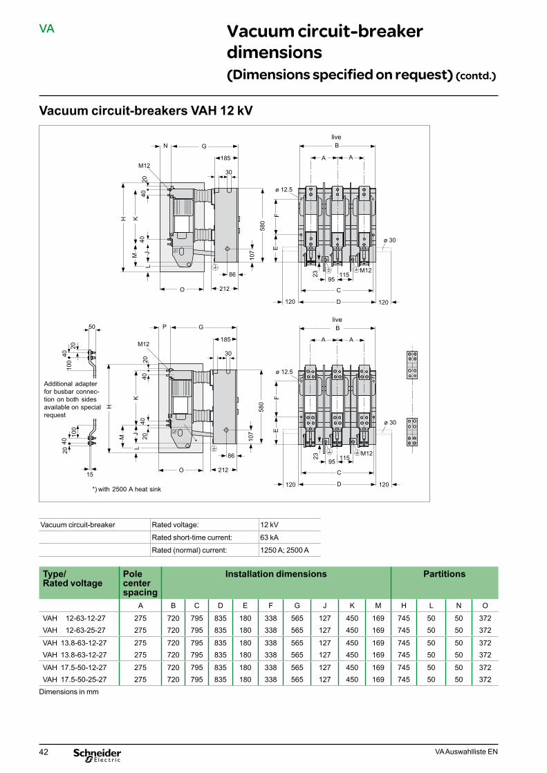
42 VA Auswahlliste EN
VA Vacuum circuit-breakerdimensions(Dimensions specified on request) (contd.)
Vacuum circuit-breakers VAH 12 kV
Vacuum circuit-breaker Rated voltage: 12 kV
Rated short-time current: 63 kA
Rated (normal) current: 1250 A; 2500 A
Type/Rated voltage
Polecenterspacing
Installation dimensions Partitions
A B C D E F G J K M H L N O
VAH 12-63-12-27VAH 12-63-25-27
275275
720720
795795
835835
180180
338338
565565
127127
450450
169169
745745
5050
5050
372372
VAH 13.8-63-12-27VAH 13.8-63-12-27
275275
720720
795795
835835
180180
338338
565565
127127
450450
169169
745745
5050
5050
372372
VAH 17.5-50-12-27VAH 17.5-50-25-27
275275
720720
795795
835835
180180
338338
565565
127127
450450
169169
745745
5050
5050
372372
Dimensions in mm
20
23 115
120
ø 30
30
107
212
86
580
185
95
120
FE
ø 12.5
NJ
KH
L
M40
O C
D
G
M12A A
spannungsführend B
M12
40
23 115
120
ø 30
30
107
212
86
580
185
95
120
FE
ø 12.5
P
2040
JK
H
L
M
40
O
*) bei 2500 A Kühlkörper
C
D
G
M12A A
*
spannungsführend B
M1220
15
100
20
4010
0
50
2040
Zusatzadapter fürbeidseitigenSchienenanschlussauf besondereBestellung
Additional adapter for busbar connec-tion on both sides available on special request
*) with 2500 A heat sink
live
live

43VA Auswahlliste EN
VA Vacuum circuit-breakerdimensions(Dimensions specified on request) (contd.)
Vacuum circuit-breakers VAH 12 / 13.8 / 17.5 kV
Vacuum circuit-breaker Rated voltage: 12 kV 13.8 kV 17.5 kV
Rated short-time current: 63 kA 63 kA 63 kA
Rated (normal) current: 3150 A 3150 A 3150 A
Type/Rated voltage
Polecenterspacing
Installation dimensions Partitions
A B C D E F G J K M H L N O
VAH 12-63-31-27VAH 13.8-63-31-27VAH 17.5-50-31-27
275275275
700700700
795795795
835835835
180180180
338338338
565565565
127127127
450450450
169169169
---
505050
---
372372372
Dimensions in mm
Center of gravity
Control and auxiliary lines
Center of gravity
Connection to earth M12

44 VA Auswahlliste EN
VA Vacuum circuit-breakerdimensions(Dimensions specified on request) (contd.)
Vacuum circuit-breakers VAH 12 / 15.8 / 17.5 kV
Vacuum circuit-breaker Rated voltage: 12 kV 13.8 (15.8) kV 17.5 kV
Rated short-time current: 50/63 kA 63 kA 40/50 kA
Rated (normal) current: 4000/5000/8000 A 4000/5000/8000 A 4000/5000/8000 A
Type/Rated voltage
Polecenterspacing
Installation dimensions Partitions
A B C D E F G J K M H L N O
VAH 12-50-40-27 275 790 795 835 140 378 693 115 344 205 1025 190 40 490
VAH 12-63-40-27 275 790 795 835 140 378 693 115 344 205 1025 190 40 490
VAH 12-50-50-27 275 790 795 835 140 378 693 115 344 205 1025 190 40 490
VAH 12-63-50-27 275 790 795 835 140 378 693 115 344 205 1025 190 40 490
VAH 12-63-80-27 275 790 795 835 140 378 693 115 344 205 1025 190 40 490
VAH 13.8-63-40-27 275 790 795 835 140 378 693 115 344 205 1025 190 40 490
VAH 13.8-63-50-27 275 790 795 835 140 378 693 115 344 205 1025 190 40 490
VAH 13.8-63-80-27 275 790 795 835 140 378 693 115 344 205 1025 190 40 490
VAH 17.5-50-40-27 275 790 795 835 140 378 693 115 344 205 1025 190 40 490
VAH 17.5-50-50-27 275 790 795 835 140 378 693 115 344 205 1025 190 40 490
VAH 17.5-50-80-27 275 790 795 835 140 378 693 115 344 205 1025 190 40 490Dimensions in mm
M12
23
115
30
107
212
86
580
185
95C
D
A A
spannungsführend B
O
H
ML
KJ
4040
276
40
4040
EF
30
GN
live

45VA Auswahlliste EN
VA Vacuum circuit-breakerdimensions(Dimensions specified on request) (contd.)
Vacuum circuit-breakers VXA 27 kV - for railway applications
VXA 6312/27-250 VXA 8012/27-250 VXA 8020/27-250
Vacuum circuit-breaker Rated voltage: 27 kV 27 kV 27 kV
Rated short-time current: 25 kA 31.5 kA 31.5 kA
Rated (normal) current: 1250 A 1250 A 2000 A
Terminal 2000 A
Terminal 1250 A
Control- and auxiliary lines
Earth screw M12 M12 Securing bolt 10

46 VA Auswahlliste EN
VA Vacuum circuit-breakerdimensions(Dimensions specified on request) (contd.)
Vacuum circuit-breakers VXB 27 kV - for railway applications
VXB 6312/25-250 VXB 8020/25-250
Vacuum circuit-breaker Rated voltage: 27 kV 27 kV
Rated short-time current: 25 kA 31.5 kA
Rated (normal) current: 1250 A 2000 A
Terminal 1250 A Terminal 2000 A
Control- and auxiliary lines
Earth screw M12

47VA Auswahlliste EN
VA Vacuum circuit-breakerdimensions(Dimensions specified on request) (contd.)
Chassis frame for VAA 12 kV up to 24 kV
Rated voltage Pole center spacing Main dimensionskV PMA b c d e f h i
1212
160210
671771
729829
620720
564564
660660
12851285
675775
17.5 210 971 1029 920 564 660 1285 975
2424
210275
9711101
10291159
9201050
564564
660660
12851285
9751105
Dimensions in mm
e
f
d
bc
842
h1035
PMA PMA
Rohr 60x40
100*223
*) Befestigungs- bohrung ø 18
Erdungsanschluss M12
i*
*
100*
Connection to earth M12
*) Fastening bore-hole
Pipe 60x40
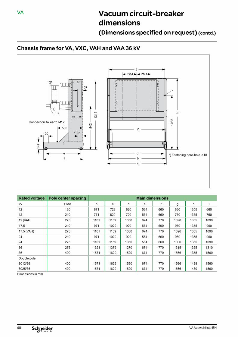
48 VA Auswahlliste EN
VA Vacuum circuit-breakerdimensions(Dimensions specified on request) (contd.)
Chassis frame for VA, VXC, VAH and VAA 36 kV
Rated voltage Pole center spacing Main dimensionskV PMA b c d e f g h i
1212
160210
671771
729829
620720
564564
660660
660760
13551355
660760
12 (VAH) 275 1101 1159 1050 674 770 1090 1355 1090
17.5 210 971 1029 920 564 660 960 1355 960
17.5 (VAH) 275 1101 1159 1050 674 770 1090 1355 1090
2424
210275
9711101
10291159
9201050
564564
660660
9601000
13551355
9601090
3636
275400
13211571
13791629
12701520
674674
770770
13151566
13551355
13101560
Double pole8012/368025/36
400400
15711571
16291629
15201520
674674
770770
15661566
14381480
15601560
Dimensions in mm
100*100
500
e
f
dbc
842
1315
1035
g
h
147
PMA PMA
*) Befestigungs- bohrung ø 18
Erdungs-anschluss M12
97
i*
*
Connection to earth M12
*) Fastening bore-hole ø18

49VA Auswahlliste EN
VA Vacuum circuit-breakerdimensions(Dimensions specified on request) (contd.)
Chassis frame for DB model
917
510458
568
684780
40
1420
500
147
588
M12
Erdungs-schraube
917
510*
*) Befestigungs- bohrung ø 18
136*
97 97
*) Fastening bore-hole ø18
Earth screw M12

50 VA Auswahlliste EN
VA Transport
TransportThe vacuum circuit-breakers are shipped with packaging.The circuit-breaker‘s weight corresponds to the selection tables. On delivery, the circuitbreakers are fully assembled and adjusted.
The vacuum circuit-breakers must be lifted in accordance with the illustration. A rope with a diameter of 12 to 15 mm or a strap is required.
Transport VXA
Example for a shipping unit, type VA, VAA, VXC, VAH
Transport VA, VAA, VXC
���
Transport VAH
����������

Appendices Notes
51VA Auswahlliste EN

VA Auswahlliste EN 02-2011
© 2
011
Sch
neid
er E
lect
ric -
All
right
s re
serv
ed
As standards, specifications and designs change from time to time, please ask for confirmation of the information given in this publication.
Publishing: Schneider ElectricDesign: Schneider ElectricPrinting:
This document has been printed on ecological paper
Schneider Electric35, rue Joseph Monier CS 30323 92506 Rueil-Malmaison Cedex, France
RCS Nanterre 954 503 439 Capital social 896 313 776 €www.schneider-electric.com