Embed Size (px)
Citation preview
Delivering the Moment
Installation and Operation Manual
Selenio 6800™ HDX6800+B2 & HDX- 6800+B4/C4HDTV Two- and Four-Channel AES Demul iplexers
Edition C
175-000231-00
Publication Information © 2014 Imagine Communications Corp. Proprietary and Confidential.
Imagine Communications considers this document and its contents to be proprietary and confidential. Except for making a reasonable number of copies for your own internal use, you may not reproduce this publication, or any part thereof, in any form, by any method, for any purpose, or in any language other than English without the written consent of Imagine Communications. All others uses are illegal.
This publication is designed to assist in the use of the product as it exists on the date of publication of this manual, and may not reflect the product at the current time or an unknown time in the future. This publication does not in any way warrant description accuracy or guarantee the use for the product to which it refers. Imagine Communications reserves the right, without notice to make such changes in equipment, design, specifications, components, or documentation as progress may warrant to improve the performance of the product.
Trademarks 6800+™, ADC™, CCS Navigator™, Channel ONE™, ChannelView™, ClipSync™, Delay™, D Series™, D Series DSX™, Deliver the Moment™, Delivering the Moment™, FAME™, Farad™, G8™, G Scribe™, HView™, IconMaster™, IconLogo™, IconSta-tion™, IconKey™, InfoCaster™, InfoCaster Creator™, InfoCaster Manager™, InfoCaster Player™, InstantOnline™, Invenio®, Live Update™, mCAPTURE™, Magellan™, Magellan CCS Navigator™, Magellan Q SEE™, MultiService SDN™, NetPlus™, NetVX™, NewsForce™, Nexio® G8™, Nexio AMP® ChannelView™, Nexio® Channel ONE™, Nexio® ClipSync™, Nexio® Delay™, Nexio® Digital Turnaround Processor™, Nexio® Farad™, Nexio® G Scribe™, Nexio® IconKey™, Nexio® IconLogo™, Nexio® IconMaster™, Nexio® IconStation™, Nexio® InfoCaster™, Nexio® InfoCaster Creator™, Nexio® InfoCaster Manag-er™, Nexio® InfoCaster Player™, Nexio® InfoCaster Traffic™, Nexio® InstantOnline™, Nexio® mCAPTURE™, Nexio® News-Force™, Nexio® NXIQ™, Nexio® Playlist™, Nexio® Remote™, Nexio®RTX Net™, Nexio® TitleMotion™, Nexio® TitleOne™, Nexio® Velocity ESX™, Nexio® Velocity PRX™, Nexio® Velocity XNG™, Nexio® Volt™, OPTO+™, Panacea™, Platinum™, Playlist™, Predator II GRF™, Predator II GX™, Punctuate™, Remote™, RTX Net™, QuiC™, Q SEE™, SD STAR™, Selenio™, Selenio 6800+™, SelenioNext™, Selenio X50™, Selenio X85™, Selenio X100™, TitleMotion™, TitleOne™, Velocity ESX™, Velocity PRX™, Velocity XNG™, Versio™, Videotek® SD STAR™, X50™, and X85™ are trademarks of Imagine Communica-tions or its subsidiaries.
Altitude Express®, Connectus®, Enabling PersonalizedTV®, ICE® Broadcast System, ICE Illustrate®, ICE Q® algorithms, ICE-PAC®, Imagine ICE®, Inscriber®, Inscriber® Connectus®, Invenio®, NEO®, Nexio®, Nexio AMP®, PersonalizedTV®, Router-Works®, Videotek®, Videotek® ASI STAR®, Videotek® GEN STAR®, and Videotek® HD STAR® are registered trademarks of Imagine Communications or its subsidiaries.
Microsoft® and Windows® are registered trademarks of Microsoft Corporation. HD BNC is a trademark of Amphenol Corporation. Some products are manufactured under license from Dolby Laboratories. Dolby and the double D symbol are registered trademarks of Dolby Laboratories. DTS Neural audio products are manufactured under license from DTS Licensing Limited. DTS and the Symbol are registered trademarks & the DTS Logos are trademarks of DTS, Inc. © 2008 2010 DTS, Inc. All other trademarks and trade names are the property of their respective companies.
Contact Information Imagine Communications has office locations around the world. For locations and contact information see: http://www.imaginecommunications.com/contact us/
Support Contact Information For support contact information see:
▪ Support Contacts: http://www.imaginecommunications.com/services/technical support/ ▪ eCustomer Portal: http://support.imaginecommunications.com
© 2014 Imagine Communications Corp. Proprietary and Confidential
Edition CMay 2007
HDX6800+B2/C2 HDX6800+B4/C4HDTV Two- and Four-Channel AES Demultiplexers
Installation and Operation Manual

Contents
PrefaceManual Information ................................................................................. i
Purpose .............................................................................................. iAudience ........................................................................................... iRevision History ............................................................................... iWriting Conventions ........................................................................ iiObtaining Documents ...................................................................... ii
Unpacking/Shipping Information .......................................................... iiiUnpacking a Product ....................................................................... iiiProduct Servicing ............................................................................ iiiReturning a Product ........................................................................ iii
Restriction on Hazardous Substances (RoHS) Compliance .................. ivWaste from Electrical and Electronic Equipment (WEEE) Compliance .vSafety ..................................................................................................... vi
Safety Terms and Symbols in this Manual ..................................... vi
Chapter 1: IntroductionOverview ..................................................................................................1Product Description ..................................................................................2
General Description ..........................................................................2Main Features ...................................................................................3
Module Descriptions ................................................................................4Front Module ....................................................................................4Back Connectors ...............................................................................6Signal Flow .....................................................................................10
HDX6800+B2/C2 and HDX6800+B4/C4 Installation and Operation Manual iii
Contents
Chapter 2: InstallationOverview ............................................................................................... 11Maximum 6800+ Frame Power Ratings ............................................... 12Unpacking the Module .......................................................................... 13
Preparing the Product for Installation ............................................ 13Checking the Packing List ............................................................. 13
Setting Jumpers ..................................................................................... 14Installing HDX6800+ Modules ............................................................ 16Upgrading Module Firmware ................................................................ 17
Upgrading the Firmware ................................................................ 17Correcting a Failed Upgrading Procedure ..................................... 21
Chapter 3: OperationOverview ............................................................................................... 23Operating Notes ..................................................................................... 24Audio Processing Information .............................................................. 25
Audio Output Channel Status ........................................................ 25Input Channel V-Bit Feedback (InxxVbitFb) ................................ 25Demux Group Control (Grp1-4 Ctrl) ............................................. 26Output Audio Rate ......................................................................... 26Audio De-embedding Channel Source Selection ........................... 26
Non-PCM Processing ............................................................................ 27Cross-Functional Parameter Changes ............................................ 27Channel Dithering .......................................................................... 29Channel Word Length .................................................................... 29Channel Fade Rate ......................................................................... 29
Changing Parameter Settings ................................................................ 30Recalling Default Parameter Settings ............................................ 31Reading Software and Hardware Versions .................................... 31
Setting HDX6800+B2/C2 and HDX6800+B4/C4 Control Parameters 32LEDs and Alarms .................................................................................. 52
Monitoring LEDs ........................................................................... 52Module Status LEDs ...................................................................... 54Alarms ............................................................................................ 55
Chapter 4: SpecificationsOverview ............................................................................................... 57Inputs ..................................................................................................... 58
iv HDX6800+B2/C2 and HDX6800+B4/C4 Installation and Operation Manual
Contents
HD-SDI Video Input .......................................................................58DARS Input ....................................................................................58
Outputs ...................................................................................................59AES Balanced Output (HDX6800+B2/B4 Only) ..........................59AES Unbalanced Output (HDX6800+C2/C4 Only) ......................59HD-SDI Video Output (Reclocked) ...............................................60
Propagation Delay ..................................................................................61Power Consumption ...............................................................................61Operating Temperature ..........................................................................61
Appendix A: Audio Bit ManipulationOverview ................................................................................................63Manipulating Channel Status Bits (C-Bit) .............................................64Manipulating Validity and User Bits (V-Bit and U-Bit) ........................67Identifying Audio Characteristics (Audio Sampling Frequency and Word Length) ...................................................................................................68
Appendix B: Communication and Control Troubleshooting Tips
Overview ................................................................................................69General Troubleshooting Steps ..............................................................70Software Communication and Control Issues ........................................71
+ Pilot Lite Fails to Communicate with Installed Modules ...........71+ Pilot Lite Does Not Find All Modules in Frame ........................73+ Pilot Lite or CCS Software Application Not Responding ..........73+ Pilot Lite Cannot Control a Module Showing in the Control Window ...................................................................73+ Pilot Lite Status Bar Reports ‘Not Ready’ ..................................74CCS Software Application or Remote Control Panel Does Not Communicate with Module ............................................................74Alarm Query Fails When a Device Reboots ...................................74
Hardware Communication and Control Issues ......................................75Frames Fail to Communicate with the PC after a Power Failure ...75Module Does Not Seem to Work ....................................................75
Contacting Customer Service .................................................................75
IndexKeywords ...............................................................................................77
HDX6800+B2/C2 and HDX6800+B4/C4 Installation and Operation Manual v

Contents
vi HDX6800+B2/C2 and HDX6800+B4/C4 Installation and Operation Manual
Preface
Manual Information
PurposeThis manual details the features, installation procedures, operational procedures, and specifications of the HDX6800+B2/C2 and HDX6800+B4/C4 HDTV Two- and Four-Channel AES Demultiplexers.
AudienceThis manual is written for engineers, technicians, and operators responsible for the installation, setup, and/or operation of HDX6800+B2/C2 and HDX6800+B4/C4 HDTV Two- and Four-Channel AES Demultiplexers.
Revision History
Table 2-1. Document Revision History
Edition Date Revision HistoryA October 2004 Initial release
B April 2006 Addition of support for SMPTE 296M, firmware upgrade tool, and index
C May 2007 Minor updates to content
HDX6800+B2/C2 and HDX6800+B4/C4 Installation and Operation Manual i
Preface
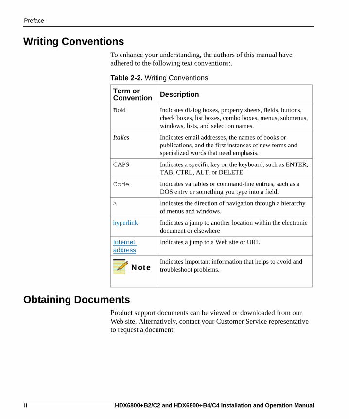
Writing ConventionsTo enhance your understanding, the authors of this manual have adhered to the following text conventions:.
Obtaining DocumentsProduct support documents can be viewed or downloaded from our Web site. Alternatively, contact your Customer Service representative to request a document.
Table 2-2. Writing Conventions
Term or Convention Description
Bold Indicates dialog boxes, property sheets, fields, buttons, check boxes, list boxes, combo boxes, menus, submenus, windows, lists, and selection names.
Italics Indicates email addresses, the names of books or publications, and the first instances of new terms and specialized words that need emphasis.
CAPS Indicates a specific key on the keyboard, such as ENTER, TAB, CTRL, ALT, or DELETE.
Code Indicates variables or command-line entries, such as a DOS entry or something you type into a field.
> Indicates the direction of navigation through a hierarchy of menus and windows.
hyperlink Indicates a jump to another location within the electronic document or elsewhere
Internet address
Indicates a jump to a Web site or URL
NoteIndicates important information that helps to avoid and troubleshoot problems.
ii HDX6800+B2/C2 and HDX6800+B4/C4 Installation and Operation Manual
Preface
Unpacking/Shipping InformationUnpacking a Product
This product was carefully inspected, tested, and calibrated before shipment to ensure years of stable and trouble-free service. 1. Check equipment for any visible damage that may have occurred
during transit. 2. Confirm that you have received all items listed on the packing list. 3. Contact your dealer if any item on the packing list is missing.4. Contact the carrier if any item is damaged.5. Remove all packaging material from the product and its associated
components before you install the unit.Keep at least one set of original packaging, in the event that you need to return a product for servicing.
Product ServicingExcept for firmware upgrades, HDX6800+B2/C2 and HDX6800+B4/C4 modules are not designed for field servicing. All hardware upgrades, modifications, or repairs require you to return the modules to the Customer Service center.
Returning a ProductIn the unlikely event that your product fails to operate properly, please contact Customer Service to obtain a Return Authorization (RA) number, then send the unit back for servicing. Keep at least one set of original packaging in the event that a product needs to be returned for service. If the original package is not available, you can supply your own packaging as long as it meets the following criteria:• The packaging must be able to withstand the product’s weight.• The product must be held rigid within the packaging.• There must be at least 2 in. (5 cm) of space between the product and
the container.• The corners of the product must be protected.
HDX6800+B2/C2 and HDX6800+B4/C4 Installation and Operation Manual iii

Preface
Ship products back to us for servicing prepaid and, if possible, in the original packaging material. If the product is still within the warranty period, we will return the product prepaid after servicing.
Restriction on Hazardous Substances (RoHS) Compliance
Directive 2002/95/EC—commonly known as the European Union (EU) Restriction on Hazardous Substances (RoHS)—sets limits on the use of certain substances found in electrical and electronic equipment. The intent of this legislation is to reduce the amount of hazardous chemicals that may leach out of landfill sites or otherwise contaminate the environment during end-of-life recycling. The Directive, which took effect on July 1, 2006, refers to the following hazardous substances: • Lead (Pb)• Mercury (Hg)• Cadmium (Cd)• Hexavalent Chromium (Cr-V1)• Polybrominated Biphenyls (PBB)• Polybrominated Diphenyl Ethers (PBDE)According to this EU Directive, all products sold in the European Union will be fully RoHS-compliant and “lead-free.” (See our Web site, www.broadcast.harris.com/leitch, for more information on dates and deadlines for compliance.) Spare parts supplied for the repair and upgrade of equipment sold before July 1, 2006 are exempt from the legislation. Equipment that complies with the EU directive will be marked with a RoHS-compliant emblem, as shown in Figure P-1.
Figure P-1. RoHS Compliance Emblem
iv HDX6800+B2/C2 and HDX6800+B4/C4 Installation and Operation Manual
Preface
Waste from Electrical and Electronic Equipment (WEEE) Compliance
The European Union (EU) Directive 2002/96/EC on Waste from Electrical and Electronic Equipment (WEEE) deals with the collection, treatment, recovery, and recycling of electrical and electronic waste products. The objective of the WEEE Directive is to assign the responsibility for the disposal of associated hazardous waste to either the producers or users of these products. As of August 13, 2005, producers or users will be required to recycle electrical and electronic equipment at end of its useful life, and may not dispose of the equipment in landfills or by using other unapproved methods. (Some EU member states may have different deadlines.)In accordance with this EU Directive, companies selling electric or electronic devices in the EU will affix labels indicating that such products must be properly recycled. (See our Web site, www.broadcast.harris.com/leitch, for more information on dates and deadlines for compliance.) Contact your local sales representative for information on returning these products for recycling. Equipment that complies with the EU directive will be marked with a WEEE-compliant emblem, as shown in Figure P-2.
Figure P-2. WEEE Compliance Emblem
HDX6800+B2/C2 and HDX6800+B4/C4 Installation and Operation Manual v
Preface
SafetyCarefully review all safety precautions to avoid injury and prevent damage to this product or any products connected to it. If this product is rack-mountable, it should be mounted in an appropriate rack using the rack-mounting positions and rear support guides provided. It is recommended that each frame be connected to a separate electrical circuit for protection against circuit overloading. If this product relies on forced air cooling, it is recommended that all obstructions to the air flow be removed prior to mounting the frame in the rack. If this product has a provision for external earth grounding, it is recommended that the frame be grounded to earth via the protective earth ground on the rear panel.IMPORTANT! Only qualified personnel should perform service procedures.
Safety Terms and Symbols in this ManualWARNINGStatements identifying conditions or practices that may result in personal injury or loss of life. High voltage is present.
CAUTIONStatements identifying conditions or practices that can result in damage to the equipment or other property.
vi HDX6800+B2/C2 and HDX6800+B4/C4 Installation and Operation Manual
Chapter 1
Introduction
OverviewThe HDX6800+B2/C2 and HDX6800+B4/C4 are two- and four-channel high-definition audio demultiplexers, respectively. The HDX6800+B2 and HDX6800+C2 modules can de-embed two AES audio signals from a provided HD video signal, while the HDX6800+B4 and HDX6800+C4 can de-embed four AES audio signals.HDX6800+B2/B4 module versions provide balanced AES outputs, while HDX6800+C2/C4 module versions provide unbalanced AES outputs.
The following topics are described in this chapter:• “Product Description” on page 2• “Front Module” on page 4• “Back Connectors” on page 6• “Signal Flow” on page 10
HDX6800+B2/C2 and HDX6800+B4/C4 Installation and Operation Manual 1
Chapter 1: Introduction
Product Description
General DescriptionThe HDX6800+B2/C2 and HDX6800+B4/C4 HDTV Two and Four Channel AES Demultiplexers can (respectively) de-embed two and four AES audio signals from a single 1.5 Gb/s HD video signal in both balanced (B2 and B4) and unbalanced (C2 and C4) formats.Following SMPTE 299M specifications, these demultiplexers are able to de-embed to up to four AES audio signals from HD inputs; an included unbalanced DARS input provides AES-11 compliance. These modules can either be controlled locally (via card edge) or controlled and monitored remotely (with software applications such as +Pilot Lite™, CCS™ Pilot™, and CCS Navigator™, or CCS-compliant remote control panels and other products).Four module types are available:• HDX6800+B2 has one unbalanced DARS input, one balanced
DARS input, one HD-SDI video input, four HD-SDI reclocked outputs, and two balanced AES output channels.
• HDX6800+B4 has one unbalanced DARS input, one balanced DARS input, one HD-SDI video input, four HD-SDI reclocked outputs, and four balanced AES output channels.
• HDX6800+C2 has one unbalanced DARS input, one HD-SDI video input, four HD-SDI reclocked outputs, and two unbalanced AES output channels.
• HDX6800+C4 has one unbalanced DARS input, one HD-SDI video input, four HD-SDI reclocked outputs, and four unbalanced AES output channels.
The back connectors for both module types require two frame slots within an FR6802+XF frame (there is no backward-compatibility provided for use with 6800/7000 series frames).
2 HDX6800+B2/C2 and HDX6800+B4/C4 Installation and Operation Manual
Chapter 1: Introduction
Main FeaturesOther HDX6800+B2/C2 and HDX6800+B4/C4 features include the following:• Inputs:
• One SMPTE 292M HD-SDI input• One unbalanced DARS AES reference input• One balanced DARS AES reference input (HDX6800+B2/B4
versions only)• Outputs:
• Four SMPTE 292M HD-SDI reclocked outputs• Two AES digital audio outputs (HDX6800+B2/C2 versions)• Four AES digital audio outputs (HDX6800+B4/C4 versions)
• Automatic detection of all SMPTE 292M HDTV video standards• Auto-detection of input video standard, or user-selection of
standard• 24-bit AES audio de-embedding• Audio processing amplification with controls for delay, gain,
invert, channel multiplexing and dithering• 16-bit, 20-bit, or 24-bit audio processing (selectable word length in
channel pairs)• Audio test tone generating• Programmable audio delays (up to 1.3 sec)• Card-edge LEDs to indicate audio and video signal presence and
module failure• Serial and Ethernet remote control and monitoring• Compliance with AES11• Support for SMPTE 296M (50, 59.94, and 60 Hz rates)
HDX6800+B2/C2 and HDX6800+B4/C4 Installation and Operation Manual 3
Chapter 1: Introduction
Module Descriptions
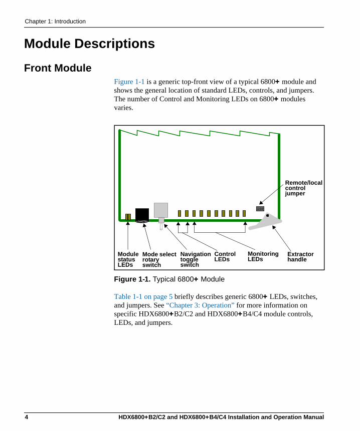
Front ModuleFigure 1-1 is a generic top-front view of a typical 6800+ module and shows the general location of standard LEDs, controls, and jumpers. The number of Control and Monitoring LEDs on 6800+ modules varies.
Figure 1-1. Typical 6800+ Module
Table 1-1 on page 5 briefly describes generic 6800+ LEDs, switches, and jumpers. See “Chapter 3: Operation” for more information on specific HDX6800+B2/C2 and HDX6800+B4/C4 module controls, LEDs, and jumpers.
Module status LEDs
Mode select rotary switch
Navigation toggle switch
Monitoring LEDs
Remote/local control jumper
Extractor handle
Control LEDs
4 HDX6800+B2/C2 and HDX6800+B4/C4 Installation and Operation Manual
Chapter 1: Introduction
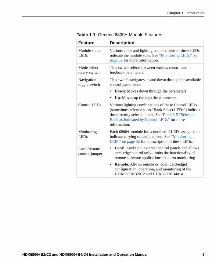
Table 1-1. Generic 6800+ Module Features
Feature DescriptionModule status LEDs
Various color and lighting combinations of these LEDs indicate the module state. See “Monitoring LEDs” on page 52 for more information.
Mode select rotary switch
This switch selects between various control and feedback parameters.
Navigation toggle switch
This switch navigates up and down through the available control parameters:• Down: Moves down through the parameters• Up: Moves up through the parameters
Control LEDs Various lighting combinations of these Control LEDs (sometimes referred to as “Bank Select LEDs”) indicate the currently selected bank. See Table 3-5 “Selected Bank as Indicated by Control LEDs” for more information.
Monitoring LEDs
Each 6800+ module has a number of LEDs assigned to indicate varying states/functions. See “Monitoring LEDs” on page 52 for a description of these LEDs.
Local/remote control jumper
• Local: Locks out external control panels and allows card-edge control only; limits the functionality of remote software applications to alarm monitoring
• Remote: Allows remote or local (card-edge) configuration, operation, and monitoring of the HDX6800+B2/C2 and HDX6800+B4/C4
HDX6800+B2/C2 and HDX6800+B4/C4 Installation and Operation Manual 5
Chapter 1: Introduction
Back ConnectorsHDX6800+B2
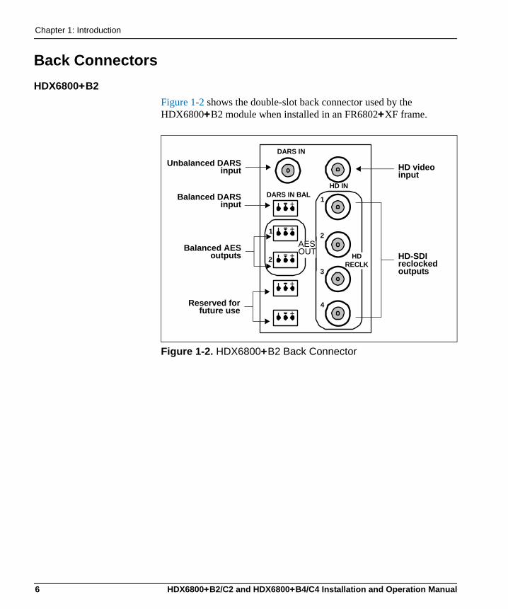
Figure 1-2 shows the double-slot back connector used by the HDX6800+B2 module when installed in an FR6802+XF frame.
Figure 1-2. HDX6800+B2 Back Connector
HD IN
1
2
3
4
DARS IN
DARS IN BAL
AESOUT HD
RECLK
+
+
+
+
+
1
2
Unbalanced DARSinput
Balanced DARSinput
Balanced AESoutputs
HD video input
HD-SDI reclocked outputs
Reserved forfuture use
AES OUT
6 HDX6800+B2/C2 and HDX6800+B4/C4 Installation and Operation Manual
Chapter 1: Introduction
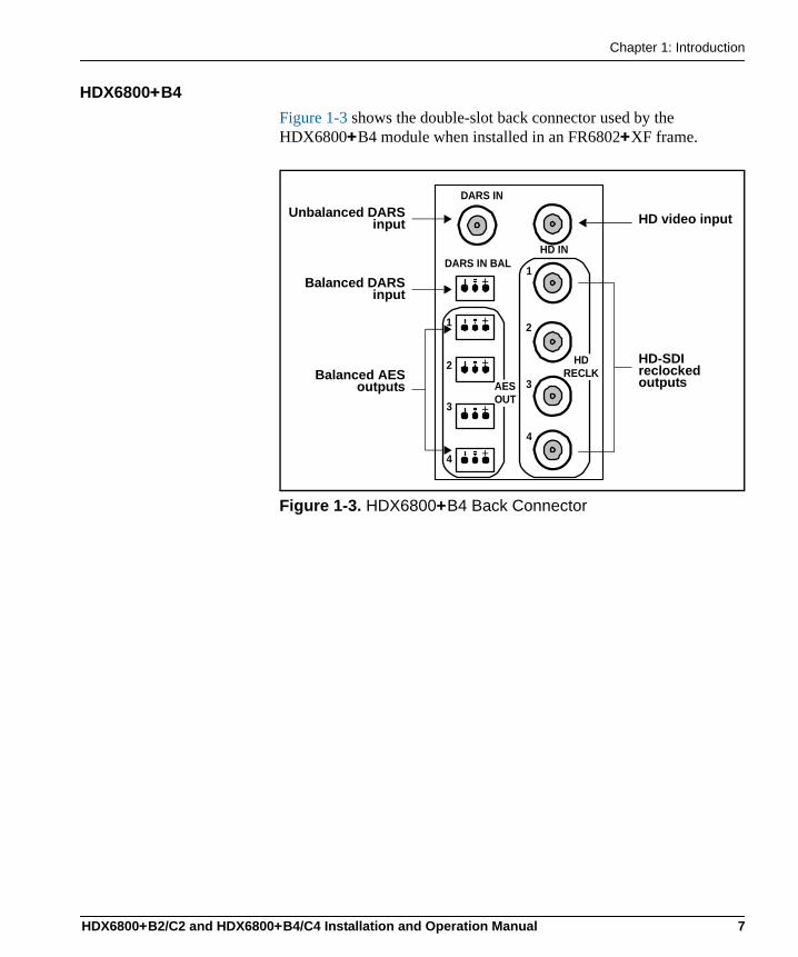
HDX6800+B4Figure 1-3 shows the double-slot back connector used by the HDX6800+B4 module when installed in an FR6802+XF frame.
Figure 1-3. HDX6800+B4 Back Connector
HD IN
1
2
DARS IN
DARS IN BAL
3
4
+
+
+
1
2
3
4
AESOUT
+
+
HDRECLK
Unbalanced DARSinput
Balanced DARSinput
Balanced AESoutputs
HD video input
HD-SDI reclocked outputs
HDX6800+B2/C2 and HDX6800+B4/C4 Installation and Operation Manual 7
Chapter 1: Introduction
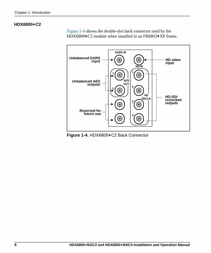
HDX6800+C2Figure 1-4 shows the double-slot back connector used by the HDX6800+C2 module when installed in an FR6802+XF frame.
Figure 1-4. HDX6800+C2 Back Connector
HD IN
1
2
3
4
DARS IN
1
2
AESOUT
HDRECLK
Unbalanced DARSinput
Unbalanced AESoutputs
HD video input
HD-SDI reclocked outputs
Reserved forfuture use
8 HDX6800+B2/C2 and HDX6800+B4/C4 Installation and Operation Manual
Chapter 1: Introduction
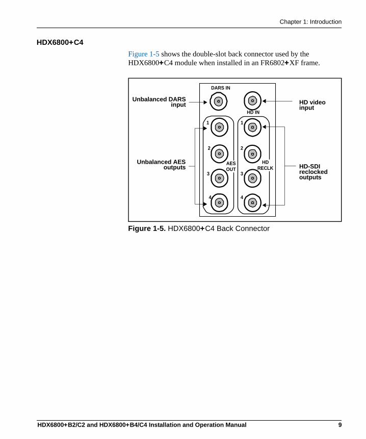
HDX6800+C4Figure 1-5 shows the double-slot back connector used by the HDX6800+C4 module when installed in an FR6802+XF frame.
Figure 1-5. HDX6800+C4 Back Connector
HD IN
DARS IN
AESOUT
HDRECLK
1
2
3
4
1
2
3
4
Unbalanced DARSinput
Unbalanced AESoutputs
HD video input
HD-SDI reclocked outputs
HDX6800+B2/C2 and HDX6800+B4/C4 Installation and Operation Manual 9
Chapter 1: Introduction
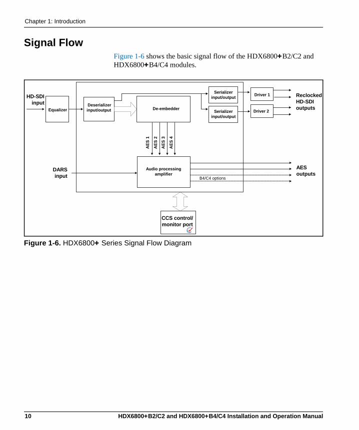
Signal FlowFigure 1-6 shows the basic signal flow of the HDX6800+B2/C2 and HDX6800+B4/C4 modules.
Figure 1-6. HDX6800+ Series Signal Flow Diagram
Equalizer Deserializerinput/output De-embedder
Serializerinput/output Driver 1
Driver 2
HD-SDIinput
ReclockedHD-SDIoutputs
Serializerinput/output
AES
1
AES
2
AES
3
AES
4Audio processing
amplifierAESoutputs
B4/C4 options
DARSinput
CCS control/monitor port
10 HDX6800+B2/C2 and HDX6800+B4/C4 Installation and Operation Manual
Chapter 2
Installation
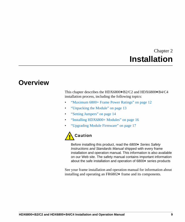
OverviewThis chapter describes the HDX6800+B2/C2 and HDX6800+B4/C4 installation process, including the following topics:• “Maximum 6800+ Frame Power Ratings” on page 12• “Unpacking the Module” on page 13• “Setting Jumpers” on page 14• “Installing HDX6800+ Modules” on page 16• “Upgrading Module Firmware” on page 17
Caution
Before installing this product, read the 6800+ Series Safety Instructions and Standards Manual shipped with every frame installation and operation manual. This information is also available on our Web site. The safety manual contains important information about the safe installation and operation of 6800+ series products
See your frame installation and operation manual for information about installing and operating an FR6802+ frame and its components.
HDX6800+B2/C2 and HDX6800+B4/C4 Installation and Operation Manual 9
Chapter 2: Installation
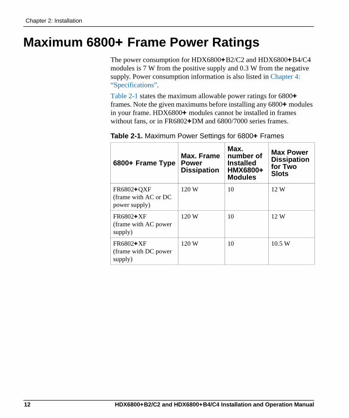
Maximum 6800+ Frame Power RatingsThe power consumption for HDX6800+B2/C2 and HDX6800+B4/C4 modules is 7 W from the positive supply and 0.3 W from the negative supply. Power consumption information is also listed in Chapter 4: “Specifications”.Table 2-1 states the maximum allowable power ratings for 6800+ frames. Note the given maximums before installing any 6800+ modules in your frame. HDX6800+ modules cannot be installed in frames without fans, or in FR6802+DM and 6800/7000 series frames.
Table 2-1. Maximum Power Settings for 6800+ Frames
6800+ Frame TypeMax. Frame Power Dissipation
Max. number of Installed HMX6800+ Modules
Max Power Dissipation for Two Slots
FR6802+QXF(frame with AC or DC power supply)
120 W 10 12 W
FR6802+XF(frame with AC power supply)
120 W 10 12 W
FR6802+XF(frame with DC power supply)
120 W 10 10.5 W
12 HDX6800+B2/C2 and HDX6800+B4/C4 Installation and Operation Manual
Chapter 2: Installation
Unpacking the Module
Preparing the Product for InstallationBefore you install the HDX6800+B2/C2 and HDX6800+B4/C4, perform the following:• Check the equipment for any visible damage that may have
occurred during transit.• Confirm receipt of all items on the packing list. See “Checking the
Packing List” for more information.
NoteContact your Customer Service representative if parts are missing or damaged.
• Remove the anti-static shipping pouch, if present, and all other packaging material.
• Retain the original packaging materials for possible re-use.
See “Unpacking/Shipping Information” on page iii for information about returning a product for servicing.
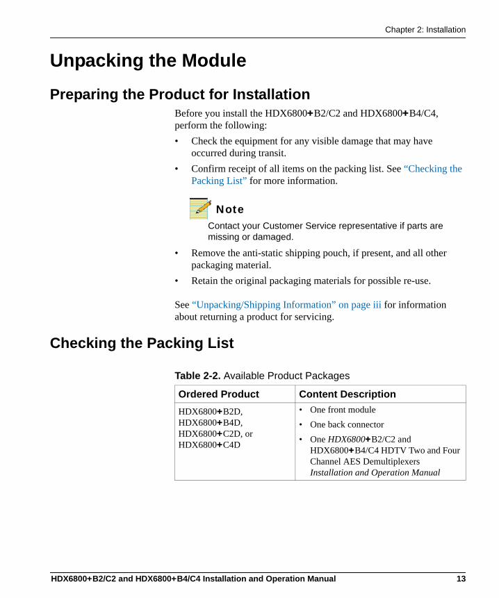
Checking the Packing List
Table 2-2. Available Product Packages
Ordered Product Content DescriptionHDX6800+B2D, HDX6800+B4D, HDX6800+C2D, or HDX6800+C4D
• One front module• One back connector• One HDX6800+B2/C2 and
HDX6800+B4/C4 HDTV Two and Four Channel AES Demultiplexers Installation and Operation Manual
HDX6800+B2/C2 and HDX6800+B4/C4 Installation and Operation Manual 13
Chapter 2: Installation
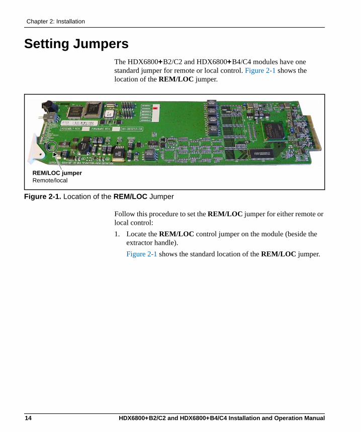
Setting JumpersThe HDX6800+B2/C2 and HDX6800+B4/C4 modules have one standard jumper for remote or local control. Figure 2-1 shows the location of the REM/LOC jumper.
Figure 2-1. Location of the REM/LOC Jumper
Follow this procedure to set the REM/LOC jumper for either remote or local control:1. Locate the REM/LOC control jumper on the module (beside the
extractor handle). Figure 2-1 shows the standard location of the REM/LOC jumper.
REM/LOC jumperRemote/local
14 HDX6800+B2/C2 and HDX6800+B4/C4 Installation and Operation Manual
Chapter 2: Installation
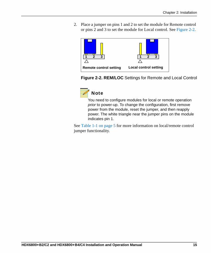
2. Place a jumper on pins 1 and 2 to set the module for Remote control or pins 2 and 3 to set the module for Local control. See Figure 2-2.
Figure 2-2. REM/LOC Settings for Remote and Local Control
NoteYou need to configure modules for local or remote operation prior to power-up. To change the configuration, first remove power from the module, reset the jumper, and then reapply power. The white triangle near the jumper pins on the module indicates pin 1.
See Table 1-1 on page 5 for more information on local/remote control jumper functionality.
1 2 3 1 2 3
Remote control setting Local control setting
HDX6800+B2/C2 and HDX6800+B4/C4 Installation and Operation Manual 15
Chapter 2: Installation
Installing HDX6800+ ModulesThe HDX6800+B2/C2 and HDX6800+B4/C4 modules have double-width back connectors. The modules cannot be installed in frames without fans or in FR6802+DM and 6800/7000 series frames.
Caution
Before inserting, removing, or replacing a back module, you must power down the frame. Failure to do so could result in damage to the frame, modules, or power supply.
These modules require no specialized installation or removal procedures. However, if you are installing both front and rear modules, ensure that the back module is installed first before plugging in the front module. Likewise, ensure that the front module is unplugged from the frame before removing the rear module. See the FR6802+ Frames Installation and Operation Manual for information about installing and operating an FR6802+ frame and its components.
16 HDX6800+B2/C2 and HDX6800+B4/C4 Installation and Operation Manual
Chapter 2: Installation
Upgrading Module FirmwareFirmware upgrading is a routine procedure that you must perform to install newer versions of software on 6800+ modules. CCS Pilot, CoPilot, or Navigator software version 3.1.1 or later is required for this procedure. The frame must contain or be connected to another frame that contains an ICE6800+ or a 6800+Eth module.
Note
Firmware for the HDX6800+B2/C2 and HDX6800+B4/C4 must be updated in Boot Loader mode.
In the unlikely event that the upgrade fails (because of such situations as network interruptions, power failures, etc.), the module may not respond to controls and will appear to be non-functional. In that event, follow the procedures described in “Correcting a Failed Upgrading Procedure” on page 21.
Upgrading the FirmwareYou can upgrade your 6800+ module’s firmware using the Software Upgrade tool. This tool is included with CCS Pilot, Co-Pilot, or Navigator software version 3.1.1 or later.
Caution
The File Transfer tab is not meant to be used for firmware upgrades. For best results, use the Software Upgrade tool to upgrade module firmware.
To upgrade your module’s firmware, follow these steps:1. Download the most recent appropriate upgrade package from our
Web site or from your CD-ROM.
HDX6800+B2/C2 and HDX6800+B4/C4 Installation and Operation Manual 17
Chapter 2: Installation
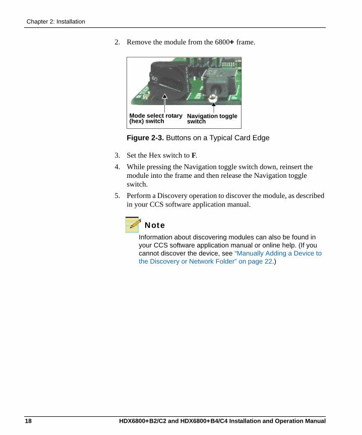
2. Remove the module from the 6800+ frame.
Figure 2-3. Buttons on a Typical Card Edge
3. Set the Hex switch to F. 4. While pressing the Navigation toggle switch down, reinsert the
module into the frame and then release the Navigation toggle switch.
5. Perform a Discovery operation to discover the module, as described in your CCS software application manual.
NoteInformation about discovering modules can also be found in your CCS software application manual or online help. (If you cannot discover the device, see “Manually Adding a Device to the Discovery or Network Folder” on page 22.)
Mode select rotary (hex) switch
Navigation toggle switch
18 HDX6800+B2/C2 and HDX6800+B4/C4 Installation and Operation Manual
Chapter 2: Installation
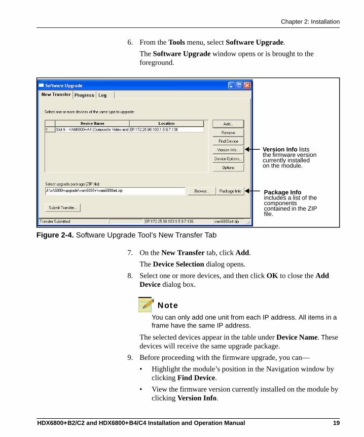
6. From the Tools menu, select Software Upgrade. The Software Upgrade window opens or is brought to the foreground.
Figure 2-4. Software Upgrade Tool’s New Transfer Tab
7. On the New Transfer tab, click Add.The Device Selection dialog opens.
8. Select one or more devices, and then click OK to close the Add Device dialog box.
NoteYou can only add one unit from each IP address. All items in a frame have the same IP address.
The selected devices appear in the table under Device Name. These devices will receive the same upgrade package.
9. Before proceeding with the firmware upgrade, you can—• Highlight the module’s position in the Navigation window by
clicking Find Device. • View the firmware version currently installed on the module by
clicking Version Info.
Package Info includes a list of the components contained in the ZIP file.
Version Info lists the firmware version currently installed on the module.
HDX6800+B2/C2 and HDX6800+B4/C4 Installation and Operation Manual 19
Chapter 2: Installation
10. Press Browse... to select the software upgrade package (ZIP file). A standard Windows File Selection dialog opens.
11. Choose the upgrade ZIP file on a local or network drive. The selected file’s path name is displayed in the edit box to the left of the Browse… button.
NoteThe extraction process on the ZIP file is handled as part of the upgrade process. You do not need to extract the files yourself. You can view the contents of the ZIP file by clicking Package Info.
12. Press Submit Transfer... A dialog box opens, requesting confirmation that you want to proceed with the request. If you have multiple devices selected, multiple transfer tasks are submitted—one per device.The transfer now progresses. You may minimize the Software Upgrade window, continue with other tasks, or switch to the Progress tab to view the status of the transfers.
NoteClosing the Software Upgrade window does not effect any of the transfer processes that may be running in the background. If you try to log off or exit the CCS software while a transfer is underway, a notification window will alert you that processes are still active and will ask if you want to terminate these processes.
13. Click on the Log tab and look at the Progress column to ensure that all files have correctly updated.
14. When the update is complete, reboot the module by manually pulling it out and then pushing it back into its slot in the frame. You cannot click Reboot Device to reboot 6800+ modules that must be upgraded in Boot Loader mode.
Your upgrade procedure is complete. If for some reason the upgrade fails, the module may not respond to controls and will appear to be non-functional. In that event, follow the procedures described in “Correcting a Failed Upgrading Procedure” on page 21.
20 HDX6800+B2/C2 and HDX6800+B4/C4 Installation and Operation Manual
Chapter 2: Installation
Correcting a Failed Upgrading ProcedureFirmware upgrades may fail in the event of network interruptions, power failures, or if the wrong upgrade package was transferred to the module. These problems can be corrected by upgrading the firmware while the module is in Boot Loader mode. The upgrade won't work unless you put the module in Boot Loader mode.
Note
If you have not already downloaded the most recent appropriate upgrade package from our Web site or from your CD-ROM, do so now.
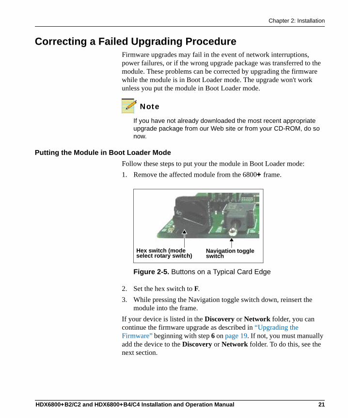
Putting the Module in Boot Loader ModeFollow these steps to put your the module in Boot Loader mode:1. Remove the affected module from the 6800+ frame.
Figure 2-5. Buttons on a Typical Card Edge
2. Set the hex switch to F. 3. While pressing the Navigation toggle switch down, reinsert the
module into the frame.If your device is listed in the Discovery or Network folder, you can continue the firmware upgrade as described in “Upgrading the Firmware” beginning with step 6 on page 19. If not, you must manually add the device to the Discovery or Network folder. To do this, see the next section.
Hex switch (mode select rotary switch)
Navigation toggle switch
HDX6800+B2/C2 and HDX6800+B4/C4 Installation and Operation Manual 21
Chapter 2: Installation
Manually Adding a Device to the Discovery or Network FolderIf your device is not listed in the Discovery or Network folder, you must manually add it to these folders. After you add the device, you can use the Software Upgrade dialog box to continue with the module firmware upgrade.To manually add a device to the Discovery or Network folder, follow these steps:1. Enter Build mode, and then drag or copy and paste the module’s
device icon from the Catalog folder into the Network or Discovery folder.
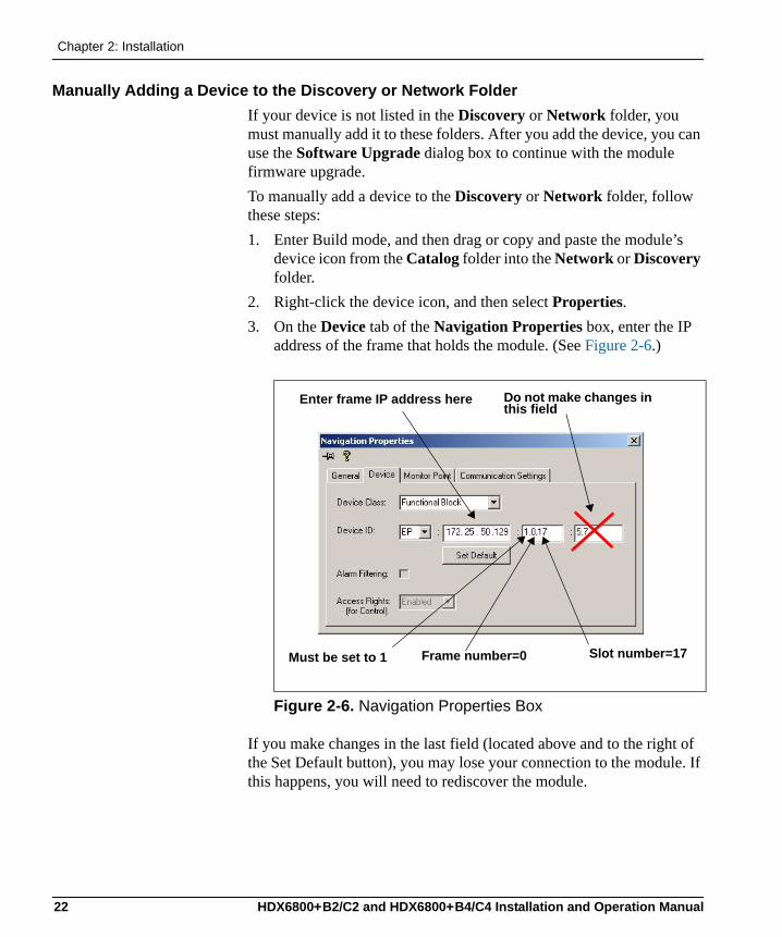
2. Right-click the device icon, and then select Properties. 3. On the Device tab of the Navigation Properties box, enter the IP
address of the frame that holds the module. (See Figure 2-6.)
Figure 2-6. Navigation Properties Box
If you make changes in the last field (located above and to the right of the Set Default button), you may lose your connection to the module. If this happens, you will need to rediscover the module.
Do not make changes in this field
Enter frame IP address here
Frame number=0 Slot number=17Must be set to 1
22 HDX6800+B2/C2 and HDX6800+B4/C4 Installation and Operation Manual
Chapter 3
Operation
OverviewThis chapter describes how to operate the HDX6800+B2/C2 and HDX6800+B4/C4 using card-edge controls only. See the following documents for information on how to operate this product remotely:• +Pilot Lite User Manual for serial control interface• CCS Pilot, CoPilot, Navigator, or RCP-CCS-1U Remote Control
Panel manual for Ethernet control interface
The following topics are discussed in this chapter:• “Operating Notes” on page 24• “Audio Processing Information” on page 25• “Non-PCM Processing” on page 27• “Changing Parameter Settings” on page 30• “Setting HDX6800+B2/C2 and HDX6800+B4/C4 Control
Parameters” on page 32• “LEDs and Alarms” on page 52
HDX6800+B2/C2 and HDX6800+B4/C4 Installation and Operation Manual 9
Chapter 2: Installation
Operating NotesWhen setting the control parameters on the HDX6800+B2/C2 and HDX6800+B4/C4, observe the following:• If you make changes to certain parameters, other related parameters
may also be affected. See the section “Setting HDX6800+B2/C2 and HDX6800+B4/C4 Control Parameters” on page 32 for more information.
• When you change a parameter, the effect is immediate. However, the module requires up to 20 seconds to save the latest change. After 20 seconds, the new settings are saved and will be restored if the module loses power and must be restarted.
• When you set the Factory Recall parameter to Yes, the module takes several seconds to reset all of the parameters to their default settings.
• The manufacturer recommends that you terminate any unused coaxial output connectors with a 75Ω terminator.
See the following topics for more operational information:• “Audio Output Channel Status” on page 25• “Input Channel V-Bit Feedback (InxxVbitFb)” on page 25• “Demux Group Control (Grp1-4 Ctrl)” on page 26• “Output Audio Rate” on page 26• “Audio De-embedding Channel Source Selection” on page 26
24 HDX6800+B2/C2 and HDX6800+B4/C4 Installation and Operation Manual
Chapter 3: Operation
Audio Processing Information
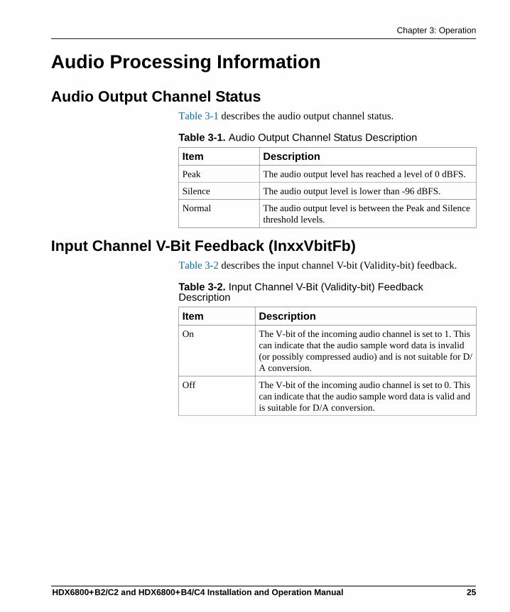
Audio Output Channel StatusTable 3-1 describes the audio output channel status.
Input Channel V-Bit Feedback (InxxVbitFb)Table 3-2 describes the input channel V-bit (Validity-bit) feedback.
Table 3-1. Audio Output Channel Status Description
Item DescriptionPeak The audio output level has reached a level of 0 dBFS.
Silence The audio output level is lower than -96 dBFS.
Normal The audio output level is between the Peak and Silence threshold levels.
Table 3-2. Input Channel V-Bit (Validity-bit) Feedback Description
Item DescriptionOn The V-bit of the incoming audio channel is set to 1. This
can indicate that the audio sample word data is invalid (or possibly compressed audio) and is not suitable for D/A conversion.
Off The V-bit of the incoming audio channel is set to 0. This can indicate that the audio sample word data is valid and is suitable for D/A conversion.
HDX6800+B2/C2 and HDX6800+B4/C4 Installation and Operation Manual 25
Chapter 2: Installation
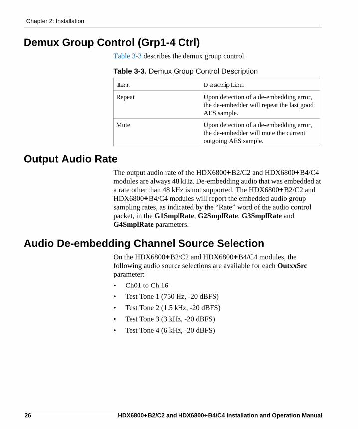
Demux Group Control (Grp1-4 Ctrl)Table 3-3 describes the demux group control.
Output Audio RateThe output audio rate of the HDX6800+B2/C2 and HDX6800+B4/C4 modules are always 48 kHz. De-embedding audio that was embedded at a rate other than 48 kHz is not supported. The HDX6800+B2/C2 and HDX6800+B4/C4 modules will report the embedded audio group sampling rates, as indicated by the “Rate” word of the audio control packet, in the G1SmplRate, G2SmplRate, G3SmplRate and G4SmplRate parameters.
Audio De-embedding Channel Source SelectionOn the HDX6800+B2/C2 and HDX6800+B4/C4 modules, the following audio source selections are available for each OutxxSrc parameter:• Ch01 to Ch 16• Test Tone 1 (750 Hz, -20 dBFS)• Test Tone 2 (1.5 kHz, -20 dBFS)• Test Tone 3 (3 kHz, -20 dBFS)• Test Tone 4 (6 kHz, -20 dBFS)
Table 3-3. Demux Group Control Description
Item Description
Repeat Upon detection of a de-embedding error, the de-embedder will repeat the last good AES sample.
Mute Upon detection of a de-embedding error, the de-embedder will mute the current outgoing AES sample.
26 HDX6800+B2/C2 and HDX6800+B4/C4 Installation and Operation Manual
Chapter 3: Operation
Non-PCM Processing
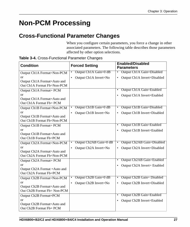
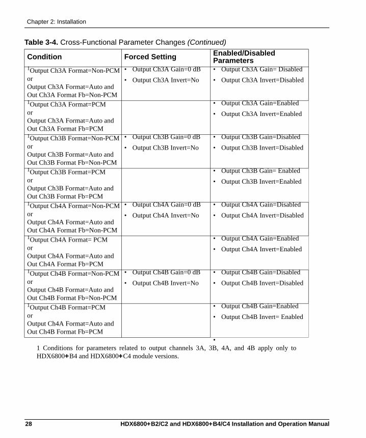
Cross-Functional Parameter ChangesWhen you configure certain parameters, you force a change in other associated parameters. The following table describes those parameters affected by other option selections.
Table 3-4. Cross-Functional Parameter Changes
Condition Forced Setting Enabled/Disabled Parameters
Output Ch1A Format=Non-PCM or Output Ch1A Format=Auto and Out Ch1A Format Fb=Non-PCM
• Output Ch1A Gain=0 dB• Output Ch1A Invert=No
• Output Ch1A Gain=Disabled• Output Ch1A Invert=Disabled
Output Ch1A Format= PCMorOutput Ch1A Format=Auto and Out Ch1A Format Fb= PCM
• Output Ch1A Gain=Enabled• Output Ch1A Invert=Enabled
Output Ch1B Format=Non-PCM or Output Ch1B Format=Auto and Out Ch1B Format Fb=Non-PCM
• Output Ch1B Gain=0 dB• Output Ch1B Invert=No
• Output Ch1B Gain=Disabled• Output Ch1B Invert=Disabled
Output Ch1B Format= PCMorOutput Ch1B Format=Auto and Out Ch1B Format Fb=PCM
• Output Ch1B Gain=Enabled• Output Ch1B Invert=Enabled
Output Ch2A Format=Non-PCM or Output Ch2A Format=Auto and Out Ch2A Format Fb=Non-PCM
• Output Ch2AB Gain=0 dB• Output Ch2A Invert=No
• Output Ch2AB Gain=Disabled• Output Ch2A Invert=Disabled
Output Ch2A Format= PCMorOutput Ch2A Format =Auto and Out Ch2A Format Fb=PCM
• Output Ch2AB Gain=Enabled• Output Ch2A Invert= Enabled
Output Ch2B Format=Non-PCM or Output Ch2B Format=Auto and Out Ch2B Format Fb= Non-PCM
• Output Ch2B Gain=0 dB• Output Ch2B Invert=No
• Output Ch2B Gain= Disabled• Output Ch2B Invert=Disabled
Output Ch2B Format=PCMorOutput Ch2B Format=Auto and Out Ch2B Format Fb= PCM
• Output Ch2B Gain=Enabled• Output Ch2B Invert=Enabled
HDX6800+B2/C2 and HDX6800+B4/C4 Installation and Operation Manual 27
Chapter 2: Installation
1Output Ch3A Format=Non-PCM or Output Ch3A Format=Auto and Out Ch3A Format Fb=Non-PCM
• Output Ch3A Gain=0 dB• Output Ch3A Invert=No
• Output Ch3A Gain= Disabled• Output Ch3A Invert=Disabled
1Output Ch3A Format=PCMorOutput Ch3A Format=Auto and Out Ch3A Format Fb=PCM
• Output Ch3A Gain=Enabled• Output Ch3A Invert=Enabled
1Output Ch3B Format=Non-PCM or Output Ch3B Format=Auto and Out Ch3B Format Fb=Non-PCM
• Output Ch3B Gain=0 dB• Output Ch3B Invert=No
• Output Ch3B Gain=Disabled• Output Ch3B Invert=Disabled
1Output Ch3B Format=PCMorOutput Ch3B Format=Auto and Out Ch3B Format Fb=PCM
• Output Ch3B Gain= Enabled• Output Ch3B Invert=Enabled
1Output Ch4A Format=Non-PCMor Output Ch4A Format=Auto and Out Ch4A Format Fb=Non-PCM
• Output Ch4A Gain=0 dB• Output Ch4A Invert=No
• Output Ch4A Gain=Disabled• Output Ch4A Invert=Disabled
1Output Ch4A Format= PCMorOutput Ch4A Format=Auto and Out Ch4A Format Fb=PCM
• Output Ch4A Gain=Enabled• Output Ch4A Invert=Enabled
1Output Ch4B Format=Non-PCM or Output Ch4B Format=Auto and Out Ch4B Format Fb=Non-PCM
• Output Ch4B Gain=0 dB• Output Ch4B Invert=No
• Output Ch4B Gain=Disabled• Output Ch4B Invert=Disabled
1Output Ch4B Format=PCMorOutput Ch4A Format=Auto and Out Ch4B Format Fb=PCM
• Output Ch4B Gain=Enabled• Output Ch4B Invert= Enabled
•1 Conditions for parameters related to output channels 3A, 3B, 4A, and 4B apply only toHDX6800+B4 and HDX6800+C4 module versions.
Table 3-4. Cross-Functional Parameter Changes (Continued)
Condition Forced Setting Enabled/Disabled Parameters
28 HDX6800+B2/C2 and HDX6800+B4/C4 Installation and Operation Manual
Chapter 3: Operation
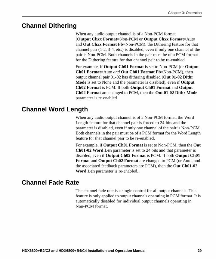
Channel DitheringWhen any audio output channel is of a Non-PCM format (Output Chxx Format=Non-PCM or Output Chxx Format=Auto and Out Chxx Format Fb=Non-PCM), the Dithering feature for that channel pair (1-2, 3-4, etc.) is disabled, even if only one channel of the pair is Non-PCM. Both channels in the pair must be of a PCM format for the Dithering feature for that channel pair to be re-enabled.For example, if Output Ch01 Format is set to Non-PCM (or Output Ch01 Format=Auto and Out Ch01 Format Fb=Non-PCM), then output channel pair 01-02 has dithering disabled (Out 01-02 Dithr Mode is set to None and the parameter is disabled), even if Output Ch02 Format is PCM. If both Output Ch01 Format and Output Ch02 Format are changed to PCM, then the Out 01-02 Dithr Mode parameter is re-enabled.
Channel Word LengthWhen any audio output channel is of a Non-PCM format, the Word Length feature for that channel pair is forced to 24-bits and the parameter is disabled, even if only one channel of the pair is Non-PCM. Both channels in the pair must be of a PCM format for the Word Length feature for that channel pair to be re-enabled.For example, if Output Ch01 Format is set to Non-PCM, then the Out Ch01-02 Word Len parameter is set to 24 bits and that parameter is disabled, even if Output Ch02 Format is PCM. If both Output Ch01 Format and Output Ch02 Format are changed to PCM (or Auto, and the associated feedback parameters are PCM), then the Out Ch01-02 Word Len parameter is re-enabled.
Channel Fade RateThe channel fade rate is a single control for all output channels. This feature is only applied to output channels operating in PCM format. It is automatically disabled for individual output channels operating in Non-PCM format.
HDX6800+B2/C2 and HDX6800+B4/C4 Installation and Operation Manual 29
Chapter 2: Installation
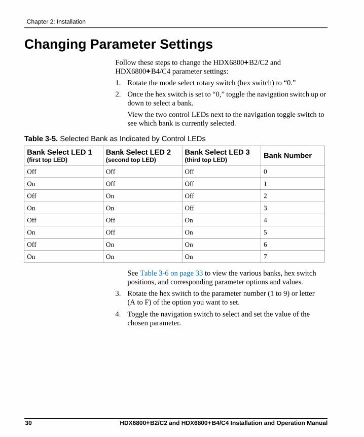
Changing Parameter SettingsFollow these steps to change the HDX6800+B2/C2 and HDX6800+B4/C4 parameter settings:1. Rotate the mode select rotary switch (hex switch) to “0.”2. Once the hex switch is set to “0,” toggle the navigation switch up or
down to select a bank. View the two control LEDs next to the navigation toggle switch to see which bank is currently selected.
See Table 3-6 on page 33 to view the various banks, hex switch positions, and corresponding parameter options and values.
3. Rotate the hex switch to the parameter number (1 to 9) or letter (A to F) of the option you want to set.
4. Toggle the navigation switch to select and set the value of the chosen parameter.
Table 3-5. Selected Bank as Indicated by Control LEDs
Bank Select LED 1(first top LED)
Bank Select LED 2(second top LED)
Bank Select LED 3(third top LED) Bank Number
Off Off Off 0
On Off Off 1
Off On Off 2
On On Off 3
Off Off On 4
On Off On 5
Off On On 6
On On On 7
30 HDX6800+B2/C2 and HDX6800+B4/C4 Installation and Operation Manual
Chapter 3: Operation
5. Rotate the hex switch to another parameter number/letter in the current bank, and then repeat step 4.orRotate the hex switch to “0” again to select a different bank, and then repeat steps 3 and 4.
Note
The manufacturer recommends that you use the available 6800+ software control options (serial/local or Ethernet/remote) to aid in viewing, setting, and confirming parameter values.
Recalling Default Parameter SettingsTable 3-6 on page 33 describe all of the parameter settings for the HDX6800+B2/C2 and HDX6800+B4/C4 modules, including the original factory defaults. To return this module to its default settings, you can either reset each parameter individually or do a global recall following this procedure:1. Rotate the hex switch to “0.”2. Toggle the navigation switch to the bank number “0.”
Use the control LEDs to verify which bank you have selected, or use an available 6800+ software control option (serial/local or Ethernet/remote) to aid in confirming your bank selection.
3. Rotate the hex switch to the global recall parameter “F.”4. Toggle the navigation switch to “On.”
Use an available 6800+ software control option to aid in viewing, setting, and confirming the parameter value.
Reading Software and Hardware VersionsThe current software version of your HDX6800+B2/C2 and HDX6800+B4/C4 module can only be viewed using a CCS-enabled control panel or a CCS software application, such as Pilot or +Pilot Lite. See your RCP-CCS-1U Installation and Operation Manual, CCS software application user manual, or CCS software application online help for information on viewing software and hardware version numbers.
HDX6800+B2/C2 and HDX6800+B4/C4 Installation and Operation Manual 31
Chapter 2: Installation
Setting HDX6800+B2/C2 and HDX6800+B4/C4 Control Parameters
The following table lists all of the available parameters and options for the HDX6800+B2/C2 and HDX6800+B4/C4. All parameters clip unless otherwise indicated.The On/Off combinations of the control LEDs on the card-edge indicate the active bank number. See “Changing Parameter Settings” on page 30 for more information.
LegendBold option = Indicates that this is the default setting for the parameter[RO] = Indicates that parameters are read-only/feedback, and cannot be used to select controls* = Indicates that this parameter is only available on HDX6800+B2 and HDX6800+B4 module versions** = Indicates that this parameter is only available on HDX6800+B4 and HDX6800+C4 module versionsSuperscript number (1) = Indicates that a footnote follows the table
Note
The sequence of options listed in the Options column mirrors the sequence achieved when you move the Navigation Toggle switch up. Parameters designated as read-only [RO] are only available from a remote CCS software control application such as Pilot or Navigator.
32 HDX6800+B2/C2 and HDX6800+B4/C4 Installation and Operation Manual
Chapter 3: Operation
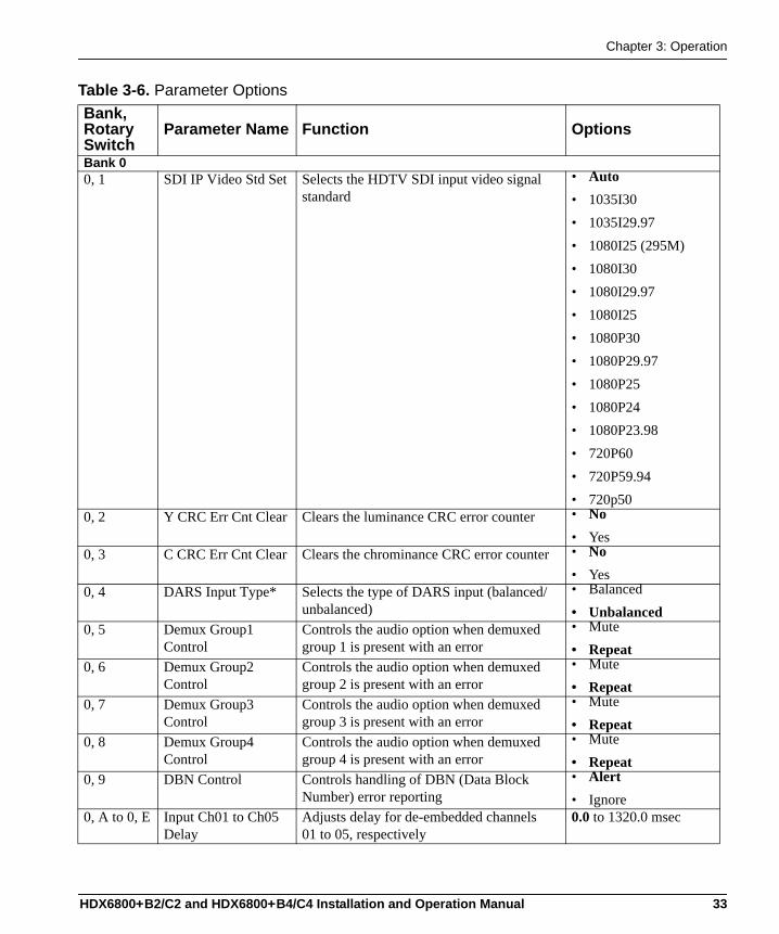
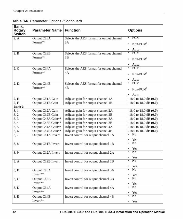
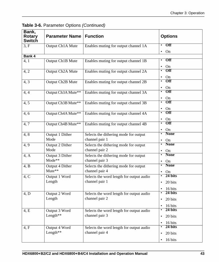
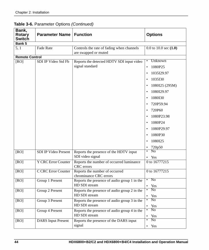
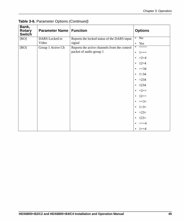
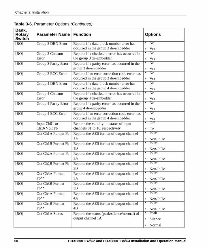
Table 3-6. Parameter Options Bank, Rotary Switch
Parameter Name Function Options
Bank 00, 1 SDI IP Video Std Set Selects the HDTV SDI input video signal
standard• Auto• 1035I30• 1035I29.97• 1080I25 (295M)• 1080I30• 1080I29.97• 1080I25• 1080P30• 1080P29.97• 1080P25• 1080P24• 1080P23.98• 720P60• 720P59.94• 720p50
0, 2 Y CRC Err Cnt Clear Clears the luminance CRC error counter • No• Yes
0, 3 C CRC Err Cnt Clear Clears the chrominance CRC error counter • No• Yes
0, 4 DARS Input Type* Selects the type of DARS input (balanced/unbalanced)
• Balanced• Unbalanced
0, 5 Demux Group1 Control
Controls the audio option when demuxed group 1 is present with an error
• Mute• Repeat
0, 6 Demux Group2 Control
Controls the audio option when demuxed group 2 is present with an error
• Mute• Repeat
0, 7 Demux Group3 Control
Controls the audio option when demuxed group 3 is present with an error
• Mute• Repeat
0, 8 Demux Group4 Control
Controls the audio option when demuxed group 4 is present with an error
• Mute• Repeat
0, 9 DBN Control Controls handling of DBN (Data Block Number) error reporting
• Alert• Ignore
0, A to 0, E Input Ch01 to Ch05 Delay
Adjusts delay for de-embedded channels 01 to 05, respectively
0.0 to 1320.0 msec
HDX6800+B2/C2 and HDX6800+B4/C4 Installation and Operation Manual 33
Chapter 2: Installation
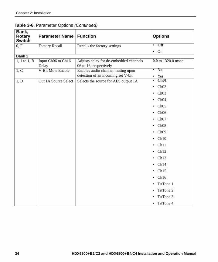
0, F Factory Recall Recalls the factory settings • Off• On
Bank 11, 1 to 1, B Input Ch06 to Ch16
Delay Adjusts delay for de-embedded channels 06 to 16, respectively
0.0 to 1320.0 msec
1, C V-Bit Mute Enable Enables audio channel muting upon detection of an incoming set V-bit
• No• Yes
1, D Out 1A Source Select Selects the source for AES output 1A • Ch01• Ch02• Ch03• Ch04• Ch05• Ch06• Ch07• Ch08• Ch09• Ch10• Ch11• Ch12• Ch13• Ch14• Ch15• Ch16• TstTone 1• TstTone 2• TstTone 3• TstTone 4
Table 3-6. Parameter Options (Continued)Bank, Rotary Switch
Parameter Name Function Options
34 HDX6800+B2/C2 and HDX6800+B4/C4 Installation and Operation Manual
Chapter 3: Operation
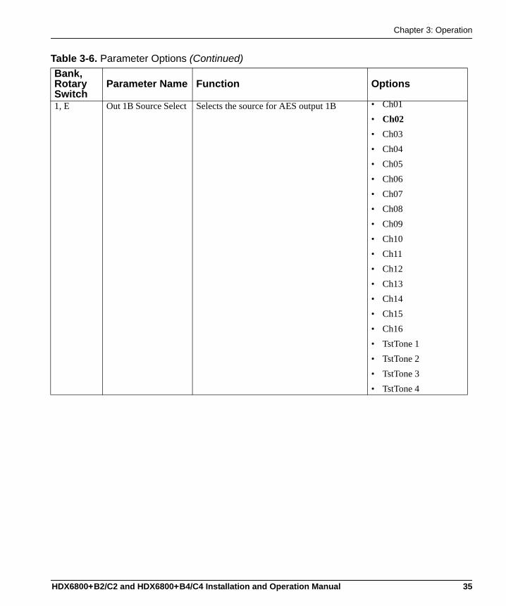
1, E Out 1B Source Select Selects the source for AES output 1B • Ch01• Ch02• Ch03• Ch04• Ch05• Ch06• Ch07• Ch08• Ch09• Ch10• Ch11• Ch12• Ch13• Ch14• Ch15• Ch16• TstTone 1• TstTone 2• TstTone 3• TstTone 4
Table 3-6. Parameter Options (Continued)Bank, Rotary Switch
Parameter Name Function Options
HDX6800+B2/C2 and HDX6800+B4/C4 Installation and Operation Manual 35

Chapter 2: Installation
1, F Out 2A Source Select Selects the source for AES output 2A • Ch01• Ch02• Ch03• Ch04• Ch05• Ch06• Ch07• Ch08• Ch09• Ch10• Ch11• Ch12• Ch13• Ch14• Ch15• Ch16• TstTone 1• TstTone 2• TstTone 3• TstTone 4
Table 3-6. Parameter Options (Continued)Bank, Rotary Switch
Parameter Name Function Options
36 HDX6800+B2/C2 and HDX6800+B4/C4 Installation and Operation Manual
Chapter 3: Operation
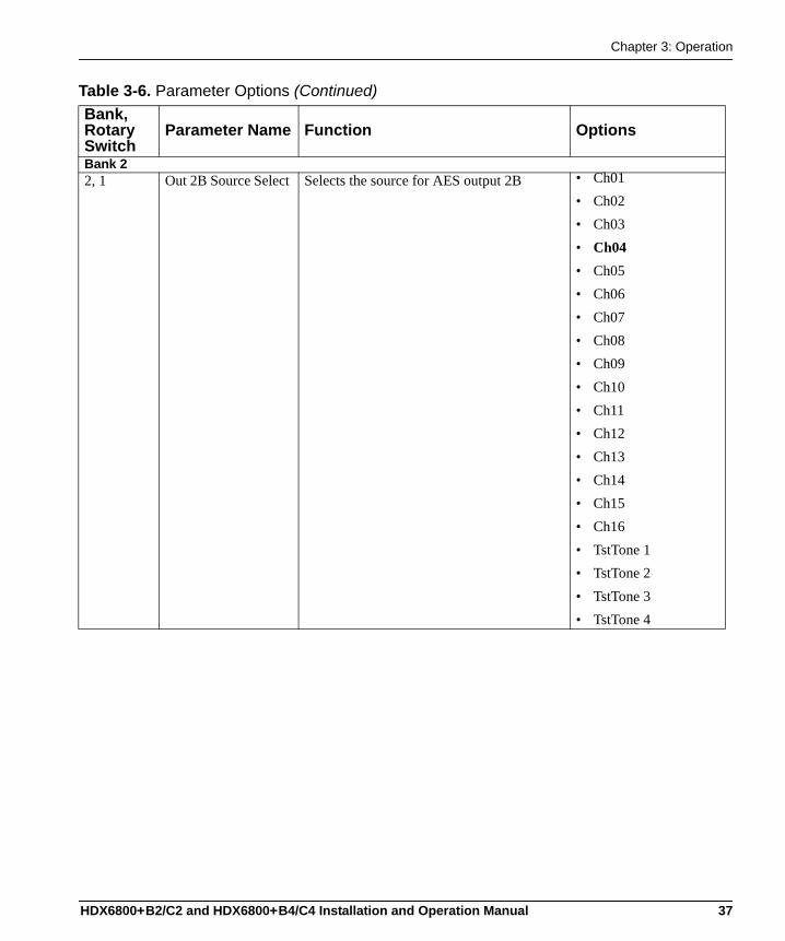
Bank 22, 1 Out 2B Source Select Selects the source for AES output 2B • Ch01
• Ch02• Ch03• Ch04• Ch05• Ch06• Ch07• Ch08• Ch09• Ch10• Ch11• Ch12• Ch13• Ch14• Ch15• Ch16• TstTone 1• TstTone 2• TstTone 3• TstTone 4
Table 3-6. Parameter Options (Continued)Bank, Rotary Switch
Parameter Name Function Options
HDX6800+B2/C2 and HDX6800+B4/C4 Installation and Operation Manual 37

Chapter 2: Installation
2, 2 Out 3A Source Select**
Selects the source for AES output 3A • Ch01• Ch02• Ch03• Ch04• Ch05• Ch06• Ch07• Ch08• Ch09• Ch10• Ch11• Ch12• Ch13• Ch14• Ch15• Ch16• TstTone 1• TstTone 2• TstTone 3• TstTone 4
Table 3-6. Parameter Options (Continued)Bank, Rotary Switch
Parameter Name Function Options
38 HDX6800+B2/C2 and HDX6800+B4/C4 Installation and Operation Manual
Chapter 3: Operation
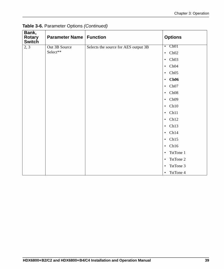
2, 3 Out 3B Source Select**
Selects the source for AES output 3B • Ch01• Ch02• Ch03• Ch04• Ch05• Ch06• Ch07• Ch08• Ch09• Ch10• Ch11• Ch12• Ch13• Ch14• Ch15• Ch16• TstTone 1• TstTone 2• TstTone 3• TstTone 4
Table 3-6. Parameter Options (Continued)Bank, Rotary Switch
Parameter Name Function Options
HDX6800+B2/C2 and HDX6800+B4/C4 Installation and Operation Manual 39
Chapter 2: Installation
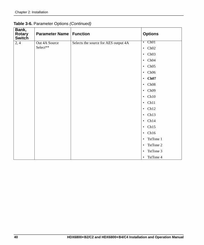
2, 4 Out 4A Source Select**
Selects the source for AES output 4A • Ch01• Ch02• Ch03• Ch04• Ch05• Ch06• Ch07• Ch08• Ch09• Ch10• Ch11• Ch12• Ch13• Ch14• Ch15• Ch16• TstTone 1• TstTone 2• TstTone 3• TstTone 4
Table 3-6. Parameter Options (Continued)Bank, Rotary Switch
Parameter Name Function Options
40 HDX6800+B2/C2 and HDX6800+B4/C4 Installation and Operation Manual
Chapter 3: Operation
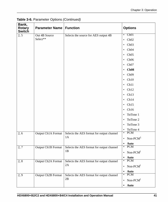
2, 5 Out 4B Source Select**
Selects the source for AES output 4B • Ch01• Ch02• Ch03• Ch04• Ch05• Ch06• Ch07• Ch08• Ch09• Ch10• Ch11• Ch12• Ch13• Ch14• Ch15• Ch16• TstTone 1• TstTone 2• TstTone 3• TstTone 4
2, 6 Output Ch1A Format Selects the AES format for output channel 1A
• PCM
• Non-PCM1
• Auto2, 7 Output Ch1B Format Selects the AES format for output channel
1B• PCM
• Non-PCM1
• Auto2, 8 Output Ch2A Format Selects the AES format for output channel
2A• PCM
• Non-PCM1
• Auto2, 9 Output Ch2B Format Selects the AES format for output channel
2B• PCM
• Non-PCM1
• Auto
Table 3-6. Parameter Options (Continued)Bank, Rotary Switch
Parameter Name Function Options
HDX6800+B2/C2 and HDX6800+B4/C4 Installation and Operation Manual 41
Chapter 2: Installation
2, A Output Ch3A Format**
Selects the AES format for output channel 3A
• PCM
• Non-PCM1
• Auto2, B Output Ch3B
Format** Selects the AES format for output channel 3B
• PCM
• Non-PCM1
• Auto2, C Output Ch4A
Format** Selects the AES format for output channel 4A
• PCM
• Non-PCM1
• Auto2, D Output Ch4B
Format** Selects the AES format for output channel 4B
• PCM
• Non-PCM1
• Auto2, E Output Ch1A Gain Adjusts gain for output channel 1A -18.0 to 18.0 dB (0.0)2, F Output Ch1B Gain Adjusts gain for output channel 1B -18.0 to 18.0 dB (0.0)Bank 33, 1 Output Ch2A Gain Adjusts gain for output channel 2A -18.0 to 18.0 dB (0.0)3, 2 Output Ch2B Gain Adjusts gain for output channel 2B -18.0 to 18.0 dB (0.0)3, 3 Output Ch3A Gain** Adjusts gain for output channel 3A -18.0 to 18.0 dB (0.0)3, 4 Output Ch3B Gain** Adjusts gain for output channel 3B -18.0 to 18.0 dB (0.0)3, 5 Output Ch4A Gain** Adjusts gain for output channel 4A -18.0 to 18.0 dB (0.0)3, 6 Output Ch4B Gain** Adjusts gain for output channel 4B -18.0 to 18.0 dB (0.0)3, 7 Output Ch1A Invert Invert control for output channel 1A • No
• Yes3, 8 Output Ch1B Invert Invert control for output channel 1B • No
• Yes3, 9 Output Ch2A Invert Invert control for output channel 2A • No
• Yes3, A Output Ch2B Invert Invert control for output channel 2B • No
• Yes3, B Output Ch3A
Invert** Invert control for output channel 3A • No
• Yes3, C Output Ch3B
Invert** Invert control for output channel 3B • No
• Yes3, D Output Ch4A
Invert** Invert control for output channel 4A • No
• Yes3, E Output Ch4B
Invert** Invert control for output channel 4B • No
• Yes
Table 3-6. Parameter Options (Continued)Bank, Rotary Switch
Parameter Name Function Options
42 HDX6800+B2/C2 and HDX6800+B4/C4 Installation and Operation Manual
Chapter 3: Operation
3, F Output Ch1A Mute Enables muting for output channel 1A • Off• On
Bank 44, 1 Output Ch1B Mute Enables muting for output channel 1B • Off
• On4, 2 Output Ch2A Mute Enables muting for output channel 2A • Off
• On4, 3 Output Ch2B Mute Enables muting for output channel 2B • Off
• On4, 4 Output Ch3A Mute** Enables muting for output channel 3A • Off
• On4, 5 Output Ch3B Mute** Enables muting for output channel 3B • Off
• On4, 6 Output Ch4A Mute** Enables muting for output channel 4A • Off
• On4, 7 Output Ch4B Mute** Enables muting for output channel 4B • Off
• On4, 8 Output 1 Dither
Mode Selects the dithering mode for output channel pair 1
• None• On
4, 9 Output 2 Dither Mode
Selects the dithering mode for output channel pair 2
• None• On
4, A Output 3 Dither Mode**
Selects the dithering mode for output channel pair 3
• None• On
4, B Output 4 Dither Mute**
Selects the dithering mode for output channel pair 4
• None• On
4, C Output 1 Word Length
Selects the word length for output audio channel pair 1
• 24 bits• 20 bits• 16 bits
4, D Output 2 Word Length
Selects the word length for output audio channel pair 2
• 24 bits• 20 bits• 16 bits
4, E Output 3 Word Length**
Selects the word length for output audio channel pair 3
• 24 bits• 20 bits• 16 bits
4, F Output 4 Word Length**
Selects the word length for output audio channel pair 4
• 24 bits• 20 bits• 16 bits
Table 3-6. Parameter Options (Continued)Bank, Rotary Switch
Parameter Name Function Options
HDX6800+B2/C2 and HDX6800+B4/C4 Installation and Operation Manual 43
Chapter 2: Installation
Bank 55, 1 Fade Rate Controls the rate of fading when channels
are swapped or muted0.0 to 10.0 sec (1.0)
Remote Control[RO] SDI IP Video Std Fb Reports the detected HDTV SDI input video
signal standard• Unknown• 1080P25• 1035I29.97• 1035I30• 1080I25 (295M)• 1080I29.97• 1080I30• 720P59.94• 720P60• 1080P23.98• 1080P24• 1080P29.97• 1080P30• 1080I25• 720p50
[RO] SDI IP Video Present Reports the presence of the HDTV input SDI video signal
• No• Yes
[RO] Y CRC Error Counter Reports the number of occurred luminance CRC errors
0 to 16777215
[RO] C CRC Error Counter Reports the number of occurred chrominance CRC errors
0 to 16777215
[RO] Group 1 Present Reports the presence of audio group 1 in the HD SDI stream
• No• Yes
[RO] Group 2 Present Reports the presence of audio group 2 in the HD SDI stream
• No• Yes
[RO] Group 3 Present Reports the presence of audio group 3 in the HD SDI stream
• No• Yes
[RO] Group 4 Present Reports the presence of audio group 4 in the HD SDI stream
• No• Yes
[RO] DARS Input Present Reports the presence of the DARS input signal
• No• Yes
Table 3-6. Parameter Options (Continued)Bank, Rotary Switch
Parameter Name Function Options
44 HDX6800+B2/C2 and HDX6800+B4/C4 Installation and Operation Manual
Chapter 3: Operation
[RO] DARS Locked to Video
Reports the locked status of the DARS input signal
• No• Yes
[RO] Group 1 Active Ch Reports the active channels from the control packet of audio group 1
• ====• 1===• =2=4• 12=4• ==34• 1=34• =234• 1234• =2==• 12==• ==3=• 1=3=• =23=• 123=• ===4• 1==4
Table 3-6. Parameter Options (Continued)Bank, Rotary Switch
Parameter Name Function Options
HDX6800+B2/C2 and HDX6800+B4/C4 Installation and Operation Manual 45
Chapter 2: Installation
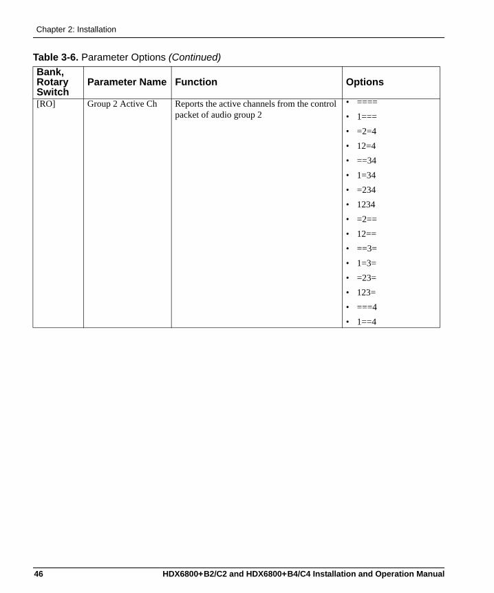
[RO] Group 2 Active Ch Reports the active channels from the control packet of audio group 2
• ====• 1===• =2=4• 12=4• ==34• 1=34• =234• 1234• =2==• 12==• ==3=• 1=3=• =23=• 123=• ===4• 1==4
Table 3-6. Parameter Options (Continued)Bank, Rotary Switch
Parameter Name Function Options
46 HDX6800+B2/C2 and HDX6800+B4/C4 Installation and Operation Manual
Chapter 3: Operation
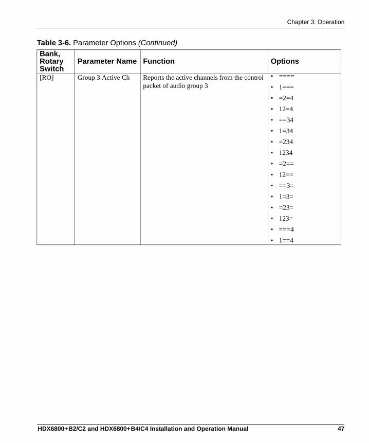
[RO] Group 3 Active Ch Reports the active channels from the control packet of audio group 3
• ====• 1===• =2=4• 12=4• ==34• 1=34• =234• 1234• =2==• 12==• ==3=• 1=3=• =23=• 123=• ===4• 1==4
Table 3-6. Parameter Options (Continued)Bank, Rotary Switch
Parameter Name Function Options
HDX6800+B2/C2 and HDX6800+B4/C4 Installation and Operation Manual 47
Chapter 2: Installation
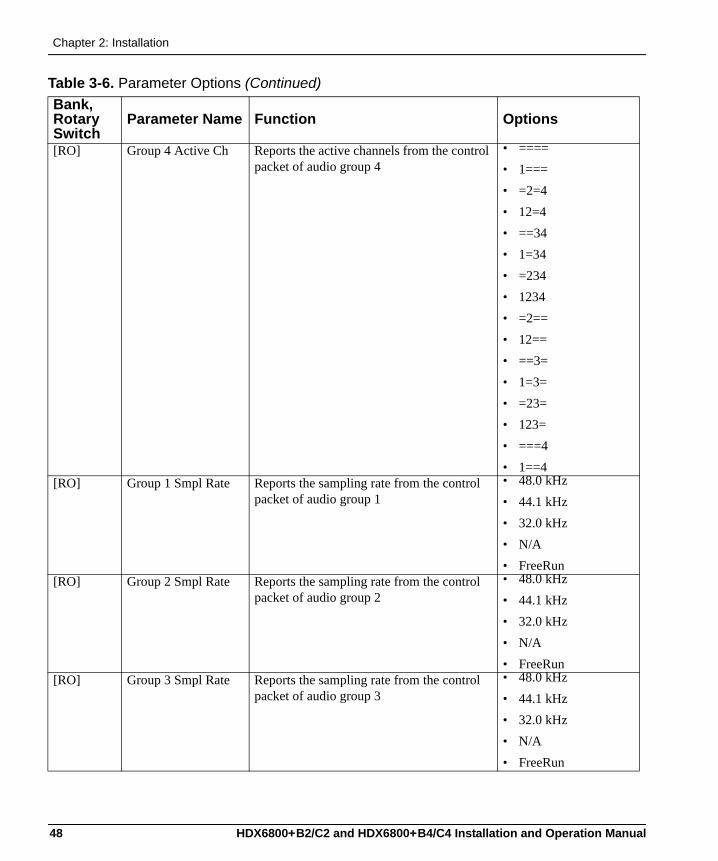
[RO] Group 4 Active Ch Reports the active channels from the control packet of audio group 4
• ====• 1===• =2=4• 12=4• ==34• 1=34• =234• 1234• =2==• 12==• ==3=• 1=3=• =23=• 123=• ===4• 1==4
[RO] Group 1 Smpl Rate Reports the sampling rate from the control packet of audio group 1
• 48.0 kHz• 44.1 kHz• 32.0 kHz• N/A• FreeRun
[RO] Group 2 Smpl Rate Reports the sampling rate from the control packet of audio group 2
• 48.0 kHz• 44.1 kHz• 32.0 kHz• N/A• FreeRun
[RO] Group 3 Smpl Rate Reports the sampling rate from the control packet of audio group 3
• 48.0 kHz• 44.1 kHz• 32.0 kHz• N/A• FreeRun
Table 3-6. Parameter Options (Continued)Bank, Rotary Switch
Parameter Name Function Options
48 HDX6800+B2/C2 and HDX6800+B4/C4 Installation and Operation Manual
Chapter 3: Operation
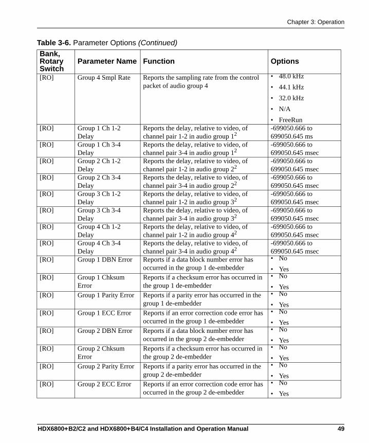
[RO] Group 4 Smpl Rate Reports the sampling rate from the control packet of audio group 4
• 48.0 kHz• 44.1 kHz• 32.0 kHz• N/A• FreeRun
[RO] Group 1 Ch 1-2 Delay
Reports the delay, relative to video, of channel pair 1-2 in audio group 12
-699050.666 to 699050.645 ms
[RO] Group 1 Ch 3-4 Delay
Reports the delay, relative to video, of channel pair 3-4 in audio group 12
-699050.666 to 699050.645 msec
[RO] Group 2 Ch 1-2 Delay
Reports the delay, relative to video, of channel pair 1-2 in audio group 22
-699050.666 to 699050.645 msec
[RO] Group 2 Ch 3-4 Delay
Reports the delay, relative to video, of channel pair 3-4 in audio group 22
-699050.666 to 699050.645 msec
[RO] Group 3 Ch 1-2 Delay
Reports the delay, relative to video, of channel pair 1-2 in audio group 32
-699050.666 to 699050.645 msec
[RO] Group 3 Ch 3-4 Delay
Reports the delay, relative to video, of channel pair 3-4 in audio group 32
-699050.666 to 699050.645 msec
[RO] Group 4 Ch 1-2 Delay
Reports the delay, relative to video, of channel pair 1-2 in audio group 42
-699050.666 to 699050.645 msec
[RO] Group 4 Ch 3-4 Delay
Reports the delay, relative to video, of channel pair 3-4 in audio group 42
-699050.666 to 699050.645 msec
[RO] Group 1 DBN Error Reports if a data block number error has occurred in the group 1 de-embedder
• No• Yes
[RO] Group 1 Chksum Error
Reports if a checksum error has occurred in the group 1 de-embedder
• No• Yes
[RO] Group 1 Parity Error Reports if a parity error has occurred in the group 1 de-embedder
• No• Yes
[RO] Group 1 ECC Error Reports if an error correction code error has occurred in the group 1 de-embedder
• No• Yes
[RO] Group 2 DBN Error Reports if a data block number error has occurred in the group 2 de-embedder
• No• Yes
[RO] Group 2 Chksum Error
Reports if a checksum error has occurred in the group 2 de-embedder
• No• Yes
[RO] Group 2 Parity Error Reports if a parity error has occurred in the group 2 de-embedder
• No• Yes
[RO] Group 2 ECC Error Reports if an error correction code error has occurred in the group 2 de-embedder
• No• Yes
Table 3-6. Parameter Options (Continued)Bank, Rotary Switch
Parameter Name Function Options
HDX6800+B2/C2 and HDX6800+B4/C4 Installation and Operation Manual 49
Chapter 2: Installation
[RO] Group 3 DBN Error Reports if a data block number error has occurred in the group 3 de-embedder
• No• Yes
[RO] Group 3 Chksum Error
Reports if a checksum error has occurred in the group 3 de-embedder
• No• Yes
[RO] Group 3 Parity Error Reports if a parity error has occurred in the group 3 de-embedder
• No• Yes
[RO] Group 3 ECC Error Reports if an error correction code error has occurred in the group 3 de-embedder
• No• Yes
[RO] Group 4 DBN Error Reports if a data block number error has occurred in the group 4 de-embedder
• No• Yes
[RO] Group 4 Chksum Error
Reports if a checksum error has occurred in the group 4 de-embedder
• No• Yes
[RO] Group 4 Parity Error Reports if a parity error has occurred in the group 4 de-embedder
• No• Yes
[RO] Group 4 ECC Error Reports if an error correction code error has occurred in the group 4 de-embedder
• No• Yes
[RO] Input Ch01 to Ch16 Vbit Fb
Reports the validity bit status of input channels 01 to 16, respectively
• Off• On
[RO] Out Ch1A Format Fb Reports the AES format of output channel 1A
• PCM• Non-PCM
[RO] Out Ch1B Format Fb Reports the AES format of output channel 1B
• PCM• Non-PCM
[RO] Out Ch2A Format Fb Reports the AES format of output channel 2A
• PCM• Non-PCM
[RO] Out Ch2B Format Fb Reports the AES format of output channel 2B
• PCM• Non-PCM
[RO] Out Ch3A Format Fb**
Reports the AES format of output channel 3A
• PCM• Non-PCM
[RO] Out Ch3B Format Fb**
Reports the AES format of output channel 3B
• PCM• Non-PCM
[RO] Out Ch4A Format Fb**
Reports the AES format of output channel 4A
• PCM• Non-PCM
[RO] Out Ch4B Format Fb**
Reports the AES format of output channel 4B
• PCM• Non-PCM
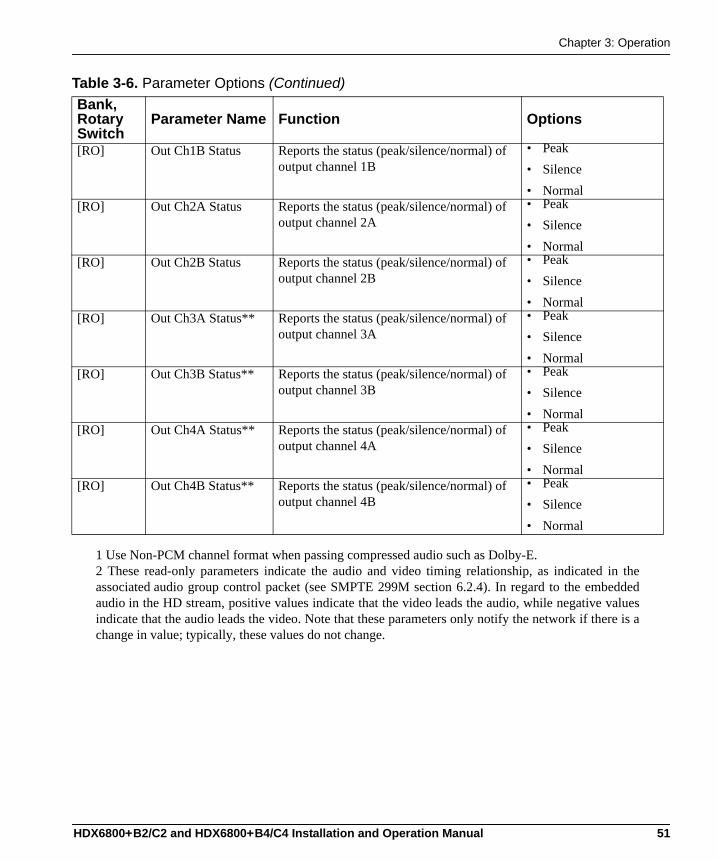
[RO] Out Ch1A Status Reports the status (peak/silence/normal) of output channel 1A
• Peak• Silence• Normal
Table 3-6. Parameter Options (Continued)Bank, Rotary Switch
Parameter Name Function Options
50 HDX6800+B2/C2 and HDX6800+B4/C4 Installation and Operation Manual
Chapter 3: Operation
[RO] Out Ch1B Status Reports the status (peak/silence/normal) of output channel 1B
• Peak• Silence• Normal
[RO] Out Ch2A Status Reports the status (peak/silence/normal) of output channel 2A
• Peak• Silence• Normal
[RO] Out Ch2B Status Reports the status (peak/silence/normal) of output channel 2B
• Peak• Silence• Normal
[RO] Out Ch3A Status** Reports the status (peak/silence/normal) of output channel 3A
• Peak• Silence• Normal
[RO] Out Ch3B Status** Reports the status (peak/silence/normal) of output channel 3B
• Peak• Silence• Normal
[RO] Out Ch4A Status** Reports the status (peak/silence/normal) of output channel 4A
• Peak• Silence• Normal
[RO] Out Ch4B Status** Reports the status (peak/silence/normal) of output channel 4B
• Peak• Silence• Normal
1 Use Non-PCM channel format when passing compressed audio such as Dolby-E.2 These read-only parameters indicate the audio and video timing relationship, as indicated in theassociated audio group control packet (see SMPTE 299M section 6.2.4). In regard to the embeddedaudio in the HD stream, positive values indicate that the video leads the audio, while negative valuesindicate that the audio leads the video. Note that these parameters only notify the network if there is achange in value; typically, these values do not change.
Table 3-6. Parameter Options (Continued)Bank, Rotary Switch
Parameter Name Function Options
HDX6800+B2/C2 and HDX6800+B4/C4 Installation and Operation Manual 51
Chapter 2: Installation
LEDs and Alarms
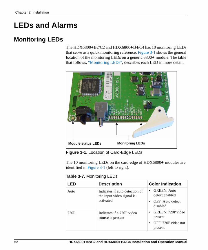
Monitoring LEDsThe HDX6800+B2/C2 and HDX6800+B4/C4 has 10 monitoring LEDs that serve as a quick monitoring reference. Figure 3-1 shows the general location of the monitoring LEDs on a generic 6800+ module. The table that follows, “Monitoring LEDs”, describes each LED in more detail.
Figure 3-1. Location of Card-Edge LEDs
The 10 monitoring LEDs on the card-edge of HDX6800+ modules are identified in Figure 3-1 (left to right).
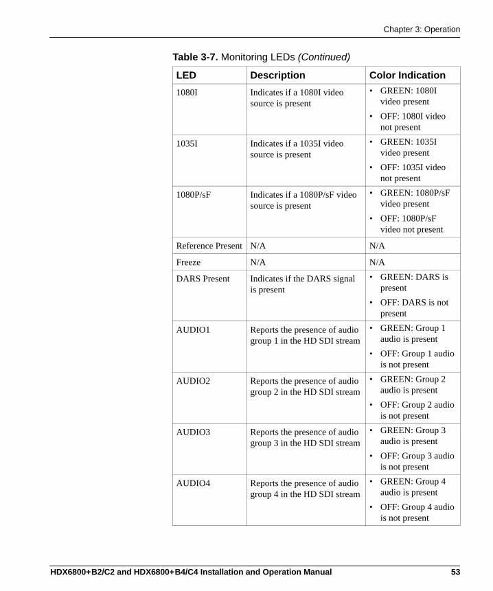
Table 3-7. Monitoring LEDs
LED Description Color IndicationAuto Indicates if auto detection of
the input video signal is activated
• GREEN: Auto detect enabled
• OFF: Auto detect disabled
720P Indicates if a 720P video source is present
• GREEN: 720P video present
• OFF: 720P video not present
Monitoring LEDsModule status LEDs
52 HDX6800+B2/C2 and HDX6800+B4/C4 Installation and Operation Manual
Chapter 3: Operation
1080I Indicates if a 1080I video source is present
• GREEN: 1080I video present
• OFF: 1080I video not present
1035I Indicates if a 1035I video source is present
• GREEN: 1035I video present
• OFF: 1035I video not present
1080P/sF Indicates if a 1080P/sF video source is present
• GREEN: 1080P/sF video present
• OFF: 1080P/sF video not present
Reference Present N/A N/A
Freeze N/A N/A
DARS Present Indicates if the DARS signal is present
• GREEN: DARS is present
• OFF: DARS is not present
AUDIO1 Reports the presence of audio group 1 in the HD SDI stream
• GREEN: Group 1 audio is present
• OFF: Group 1 audio is not present
AUDIO2 Reports the presence of audio group 2 in the HD SDI stream
• GREEN: Group 2 audio is present
• OFF: Group 2 audio is not present
AUDIO3 Reports the presence of audio group 3 in the HD SDI stream
• GREEN: Group 3 audio is present
• OFF: Group 3 audio is not present
AUDIO4 Reports the presence of audio group 4 in the HD SDI stream
• GREEN: Group 4 audio is present
• OFF: Group 4 audio is not present
Table 3-7. Monitoring LEDs (Continued)
LED Description Color Indication
HDX6800+B2/C2 and HDX6800+B4/C4 Installation and Operation Manual 53
Chapter 2: Installation
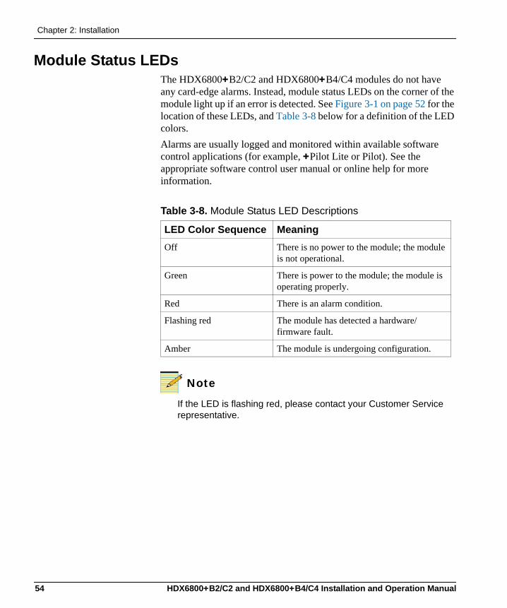
Module Status LEDsThe HDX6800+B2/C2 and HDX6800+B4/C4 modules do not have any card-edge alarms. Instead, module status LEDs on the corner of the module light up if an error is detected. See Figure 3-1 on page 52 for the location of these LEDs, and Table 3-8 below for a definition of the LED colors.Alarms are usually logged and monitored within available software control applications (for example, +Pilot Lite or Pilot). See the appropriate software control user manual or online help for more information.
Note
If the LED is flashing red, please contact your Customer Service representative.
Table 3-8. Module Status LED Descriptions
LED Color Sequence MeaningOff There is no power to the module; the module
is not operational.
Green There is power to the module; the module is operating properly.
Red There is an alarm condition.
Flashing red The module has detected a hardware/firmware fault.
Amber The module is undergoing configuration.
54 HDX6800+B2/C2 and HDX6800+B4/C4 Installation and Operation Manual
Chapter 3: Operation
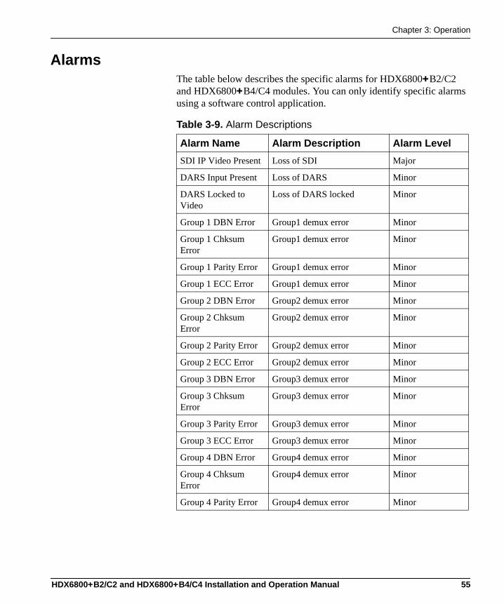
AlarmsThe table below describes the specific alarms for HDX6800+B2/C2 and HDX6800+B4/C4 modules. You can only identify specific alarms using a software control application.
Table 3-9. Alarm Descriptions
Alarm Name Alarm Description Alarm LevelSDI IP Video Present Loss of SDI Major
DARS Input Present Loss of DARS Minor
DARS Locked to Video
Loss of DARS locked Minor
Group 1 DBN Error Group1 demux error Minor
Group 1 Chksum Error
Group1 demux error Minor
Group 1 Parity Error Group1 demux error Minor
Group 1 ECC Error Group1 demux error Minor
Group 2 DBN Error Group2 demux error Minor
Group 2 Chksum Error
Group2 demux error Minor
Group 2 Parity Error Group2 demux error Minor
Group 2 ECC Error Group2 demux error Minor
Group 3 DBN Error Group3 demux error Minor
Group 3 Chksum Error
Group3 demux error Minor
Group 3 Parity Error Group3 demux error Minor
Group 3 ECC Error Group3 demux error Minor
Group 4 DBN Error Group4 demux error Minor
Group 4 Chksum Error
Group4 demux error Minor
Group 4 Parity Error Group4 demux error Minor
HDX6800+B2/C2 and HDX6800+B4/C4 Installation and Operation Manual 55
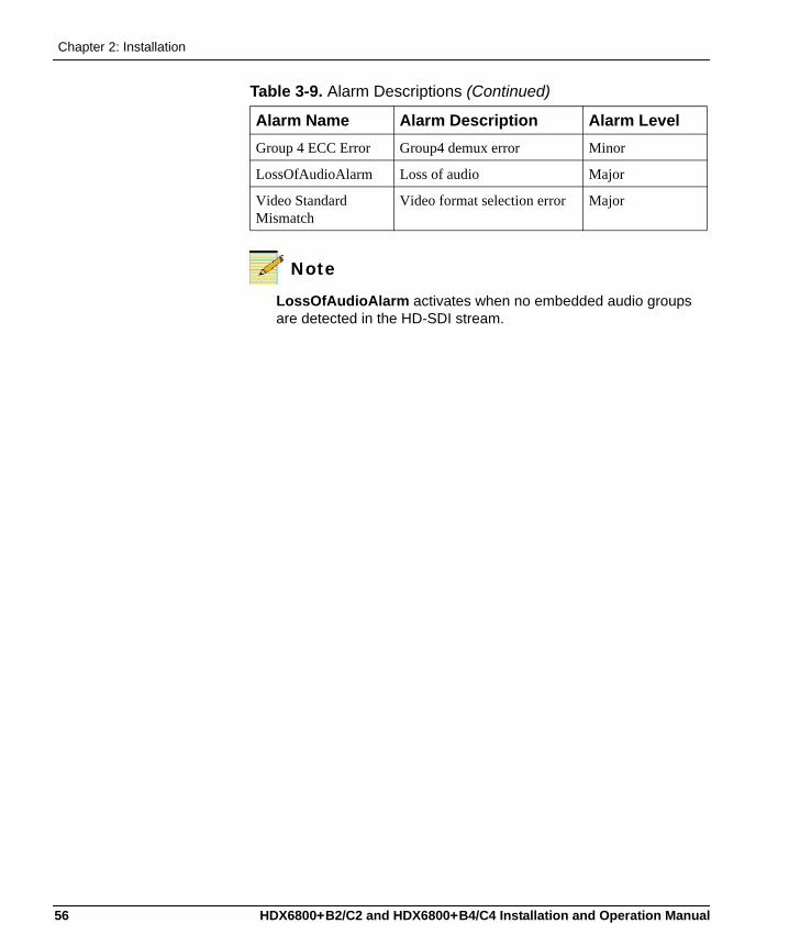
Chapter 2: Installation
Note
LossOfAudioAlarm activates when no embedded audio groups are detected in the HD-SDI stream.
Group 4 ECC Error Group4 demux error Minor
LossOfAudioAlarm Loss of audio Major
Video Standard Mismatch
Video format selection error Major
Table 3-9. Alarm Descriptions (Continued)
Alarm Name Alarm Description Alarm Level
56 HDX6800+B2/C2 and HDX6800+B4/C4 Installation and Operation Manual
Chapter 4
Specifications
OverviewThe following specification tables appear in this chapter:• “HD-SDI Video Input” on page 58• “DARS Input” on page 58• “AES Balanced Output (HDX6800+B2/B4 Only)” on page 59• “AES Unbalanced Output (HDX6800+C2/C4 Only)” on page 59• “HD-SDI Video Output (Reclocked)” on page 60• “Propagation Delay” on page 61• “Power Consumption” on page 61• “Operating Temperature” on page 61
Specifications and designs are subject to change without notice.
HDX6800+B2/C2 and HDX6800+B4/C4 Installation and Operation Manual 57
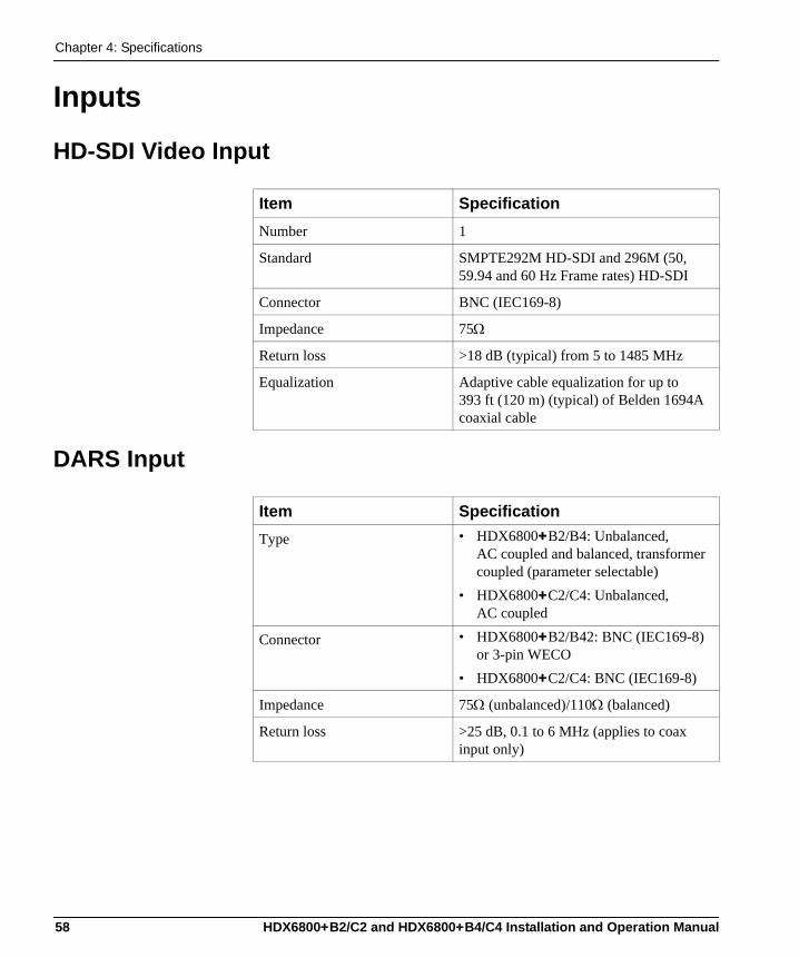
Chapter 4: Specifications
Inputs
HD-SDI Video Input
DARS Input
Item SpecificationNumber 1
Standard SMPTE292M HD-SDI and 296M (50, 59.94 and 60 Hz Frame rates) HD-SDI
Connector BNC (IEC169-8)
Impedance 75Ω
Return loss >18 dB (typical) from 5 to 1485 MHz
Equalization Adaptive cable equalization for up to 393 ft (120 m) (typical) of Belden 1694A coaxial cable
Item SpecificationType • HDX6800+B2/B4: Unbalanced,
AC coupled and balanced, transformer coupled (parameter selectable)
• HDX6800+C2/C4: Unbalanced, AC coupled
Connector • HDX6800+B2/B42: BNC (IEC169-8) or 3-pin WECO
• HDX6800+C2/C4: BNC (IEC169-8)
Impedance 75Ω (unbalanced)/110Ω (balanced)
Return loss >25 dB, 0.1 to 6 MHz (applies to coax input only)
58 HDX6800+B2/C2 and HDX6800+B4/C4 Installation and Operation Manual
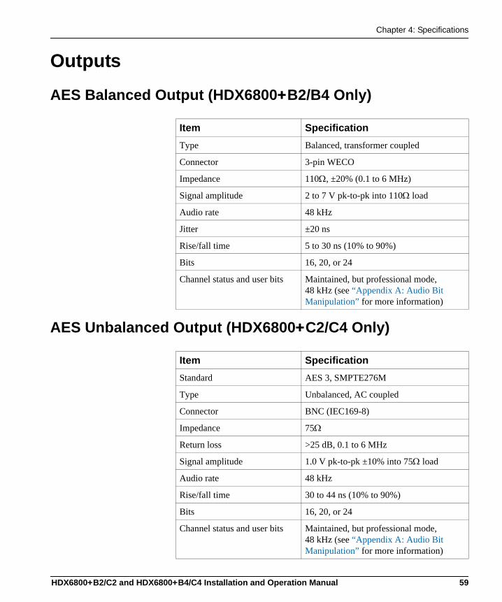
Chapter 4: Specifications
Outputs
AES Balanced Output (HDX6800+B2/B4 Only)
AES Unbalanced Output (HDX6800+C2/C4 Only)
Item SpecificationType Balanced, transformer coupled
Connector 3-pin WECO
Impedance 110Ω, ±20% (0.1 to 6 MHz)
Signal amplitude 2 to 7 V pk-to-pk into 110Ω load
Audio rate 48 kHz
Jitter ±20 ns
Rise/fall time 5 to 30 ns (10% to 90%)
Bits 16, 20, or 24
Channel status and user bits Maintained, but professional mode, 48 kHz (see “Appendix A: Audio Bit Manipulation” for more information)
Item SpecificationStandard AES 3, SMPTE276M
Type Unbalanced, AC coupled
Connector BNC (IEC169-8)
Impedance 75Ω
Return loss >25 dB, 0.1 to 6 MHz
Signal amplitude 1.0 V pk-to-pk ±10% into 75Ω load
Audio rate 48 kHz
Rise/fall time 30 to 44 ns (10% to 90%)
Bits 16, 20, or 24
Channel status and user bits Maintained, but professional mode, 48 kHz (see “Appendix A: Audio Bit Manipulation” for more information)
HDX6800+B2/C2 and HDX6800+B4/C4 Installation and Operation Manual 59
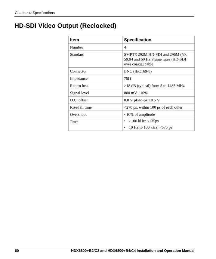
Chapter 4: Specifications
HD-SDI Video Output (Reclocked)
Item SpecificationNumber 4
Standard SMPTE 292M HD-SDI and 296M (50, 59.94 and 60 Hz Frame rates) HD-SDI over coaxial cable
Connector BNC (IEC169-8)
Impedance 75Ω
Return loss >18 dB (typical) from 5 to 1485 MHz
Signal level 800 mV ±10%
D.C. offset 0.0 V pk-to-pk ±0.5 V
Rise/fall time <270 ps, within 100 ps of each other
Overshoot <10% of amplitude
Jitter • >100 kHz: <135ps• 10 Hz to 100 kHz: <675 ps
60 HDX6800+B2/C2 and HDX6800+B4/C4 Installation and Operation Manual
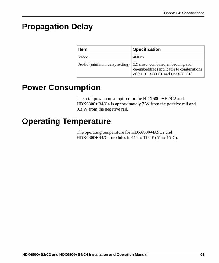
Chapter 4: Specifications
Propagation Delay
Power ConsumptionThe total power consumption for the HDX6800+B2/C2 and HDX6800+B4/C4 is approximately 7 W from the positive rail and 0.3 W from the negative rail.
Operating TemperatureThe operating temperature for HDX6800+B2/C2 and HDX6800+B4/C4 modules is 41° to 113°F (5° to 45°C).
Item SpecificationVideo 460 ns
Audio (minimum delay setting) 3.9 msec, combined embedding and de-embedding (applicable to combinations of the HDX6800+ and HMX6800+)
HDX6800+B2/C2 and HDX6800+B4/C4 Installation and Operation Manual 61

Chapter 4: Specifications
62 HDX6800+B2/C2 and HDX6800+B4/C4 Installation and Operation Manual
Appendix A
Audio Bit Manipulation
OverviewThe tables in this appendix contain information on the manipulation of bits that occur when using HDX6800+B2/C2 and HDX6800+B4/C4 modules.The following items are documented:• C-bit• V-bit and U-bit• Audio sampling frequency and word length
Table A-1. Description of Short Forms in the Appendix
RX Key TX KeyN=Not recognized N=Not transmitted
Y=Recognized Y=Transmitted
S=Recognized and stored, passed-through, or both
HDX6800+B2/C2 and HDX6800+B4/C4 Installation and Operation Manual 63
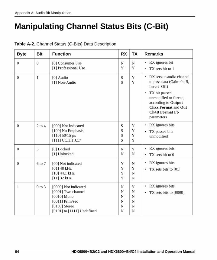
Appendix A: Audio Bit Manipulation
Manipulating Channel Status Bits (C-Bit)
Table A-2. Channel Status (C-Bits) Data Description
Byte Bit Function RX TX Remarks
0 0 [0] Consumer Use [1] Professional Use
N Y
NY
• RX ignores bit• TX sets bit to 1
0 1 [0] Audio [1] Non-Audio
SS
YY
• RX sets up audio channel to pass data (Gain=0 dB, Invert=Off)
• TX bit passed unmodified or forced, according to Output Chxx Format and Out Ch4B Format Fb parameters
0 2 to 4 [000] Not Indicated [100] No Emphasis [110] 50/15 µs [111] CCITT J.17
SSSS
YYYY
• RX ignores bits• TX passed bits
unmodified
0 5 [0] Locked [1] Unlocked
N N
Y N
• RX ignores bits• TX sets bit to 0
0 6 to 7 [00] Not indicated [01] 48 kHz [10] 44.1 kHz [11] 32 kHz
YYYY
N YNN
• RX ignores bits • TX sets bits to [01]
1 0 to 3 [0000] Not indicated [0001] Two channel [0010] Mono [0011] Prim/sec [0100] Stereo [0101] to [1111] Undefined
NNNNNN
YNNNNN
• RX ignores bits • TX sets bits to [0000]
64 HDX6800+B2/C2 and HDX6800+B4/C4 Installation and Operation Manual
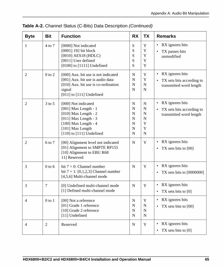
Appendix A: Audio Bit Manipulation
1 4 to 7 [0000] Not indicated [0001] 192 bit block [0010] AES18 (HDLC) [0011] User defined [0100] to [1111] Undefined
SSSSS
Y YYYY
• RX ignores bits• TX passes bits
unmodified
2 0 to 2 [000] Aux. bit use is not indicated[001] Aux. bit use is audio data[010] Aux. bit use is co-ordination signal[011] to [111] Undefined
N N N N
YYNN
• RX ignores bits• TX sets bits according to
transmitted word length
2 3 to 5 [000] Not indicated [001] Max Length - 1 [010] Max Length - 2 [011] Max Length - 3 [100] Max Length - 4 [101] Max Length [110] to [111] Undefined
N N N N N N N
NNN NY YN
• RX ignores bits• TX sets bits according to
transmitted word length
2 6 to 7 [00] Alignment level not indicated[01] Alignment to SMPTE RP155[10] Alignment to EBU R6811] Reserved
N Y • RX ignores bits• TX sets bits to [00]
3 0 to 6 bit 7 = 0: Channel numberbit 7 = 1: [0,1,2,3] Channel number[4,5,6] Multi-channel mode
N Y • RX ignores bits• TX sets bits to [0000000]
3 7 [0] Undefined multi-channel mode[1] Defined multi-channel mode
N Y • RX ignores bits• TX sets bits to [0]
4 0 to 1 [00] Not a reference [01] Grade 1 reference [10] Grade 2 reference [11] Undefined
N N N N
Y N NN
• RX ignores bits• TX sets bits to [00]
4 2 Reserved N Y • RX ignores bits• TX sets bits to [0]
Table A-2. Channel Status (C-Bits) Data Description (Continued)
Byte Bit Function RX TX Remarks
HDX6800+B2/C2 and HDX6800+B4/C4 Installation and Operation Manual 65
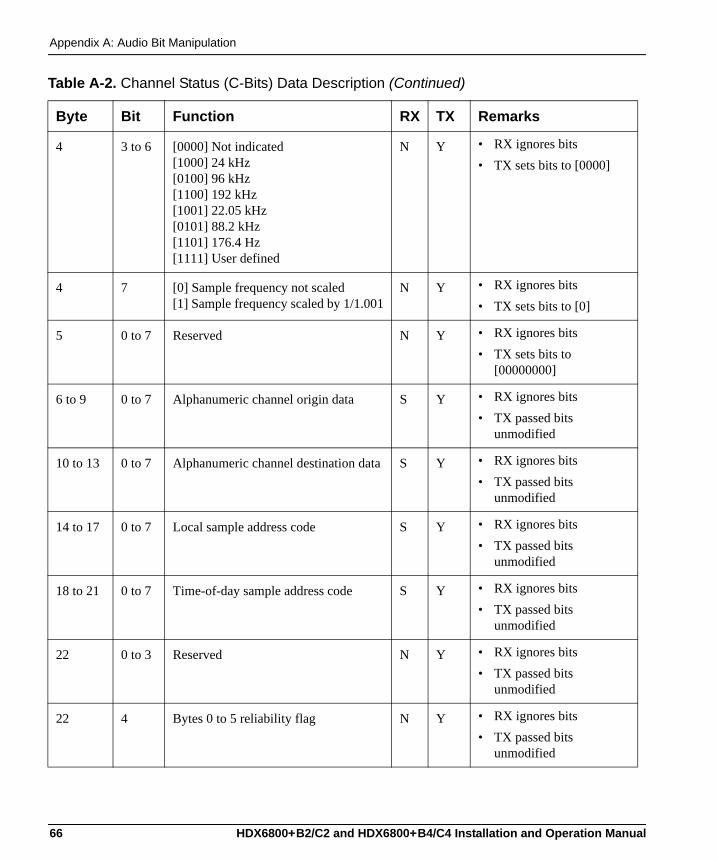
Appendix A: Audio Bit Manipulation
4 3 to 6 [0000] Not indicated[1000] 24 kHz[0100] 96 kHz[1100] 192 kHz[1001] 22.05 kHz[0101] 88.2 kHz[1101] 176.4 Hz[1111] User defined
N Y • RX ignores bits• TX sets bits to [0000]
4 7 [0] Sample frequency not scaled[1] Sample frequency scaled by 1/1.001
N Y • RX ignores bits• TX sets bits to [0]
5 0 to 7 Reserved N Y • RX ignores bits• TX sets bits to
[00000000]
6 to 9 0 to 7 Alphanumeric channel origin data S Y • RX ignores bits• TX passed bits
unmodified
10 to 13 0 to 7 Alphanumeric channel destination data S Y • RX ignores bits• TX passed bits
unmodified
14 to 17 0 to 7 Local sample address code S Y • RX ignores bits• TX passed bits
unmodified
18 to 21 0 to 7 Time-of-day sample address code S Y • RX ignores bits• TX passed bits
unmodified
22 0 to 3 Reserved N Y • RX ignores bits• TX passed bits
unmodified
22 4 Bytes 0 to 5 reliability flag N Y • RX ignores bits• TX passed bits
unmodified
Table A-2. Channel Status (C-Bits) Data Description (Continued)
Byte Bit Function RX TX Remarks
66 HDX6800+B2/C2 and HDX6800+B4/C4 Installation and Operation Manual
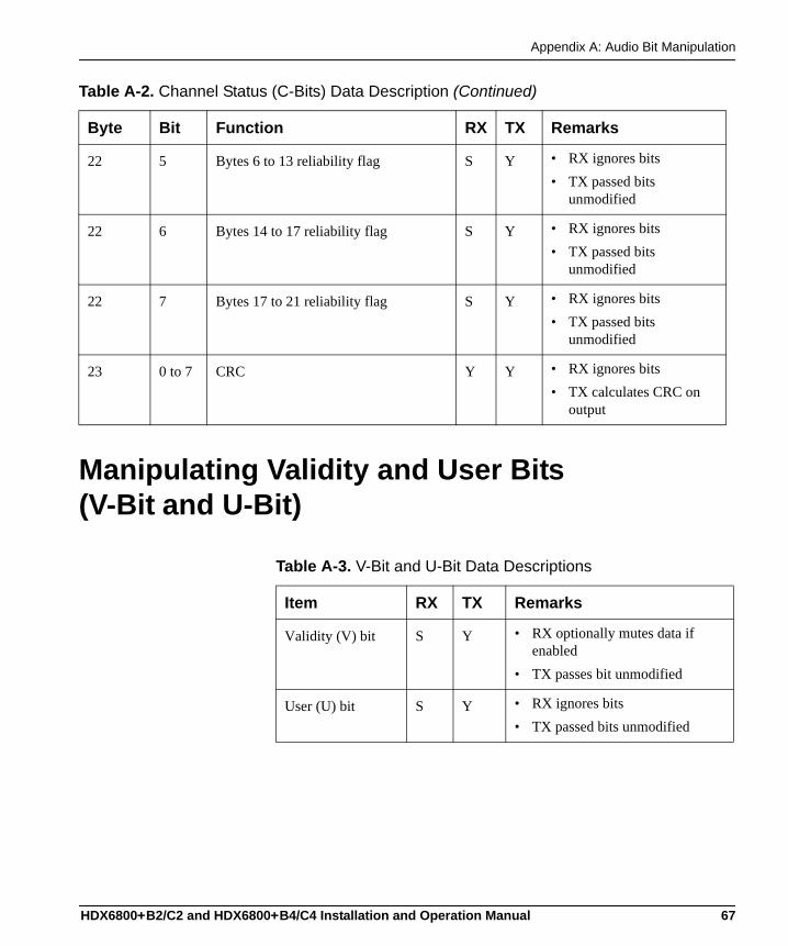
Appendix A: Audio Bit Manipulation
Manipulating Validity and User Bits (V-Bit and U-Bit)
22 5 Bytes 6 to 13 reliability flag S Y • RX ignores bits• TX passed bits
unmodified
22 6 Bytes 14 to 17 reliability flag S Y • RX ignores bits• TX passed bits
unmodified
22 7 Bytes 17 to 21 reliability flag S Y • RX ignores bits• TX passed bits
unmodified
23 0 to 7 CRC Y Y • RX ignores bits• TX calculates CRC on
output
Table A-2. Channel Status (C-Bits) Data Description (Continued)
Byte Bit Function RX TX Remarks
Table A-3. V-Bit and U-Bit Data Descriptions
Item RX TX Remarks
Validity (V) bit S Y • RX optionally mutes data if enabled
• TX passes bit unmodified
User (U) bit S Y • RX ignores bits• TX passed bits unmodified
HDX6800+B2/C2 and HDX6800+B4/C4 Installation and Operation Manual 67
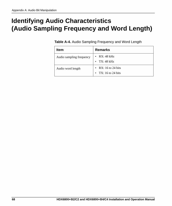
Appendix A: Audio Bit Manipulation
Identifying Audio Characteristics (Audio Sampling Frequency and Word Length)
Table A-4. Audio Sampling Frequency and Word Length
Item Remarks
Audio sampling frequency • RX: 48 kHz• TX: 48 kHz
Audio word length • RX: 16 to 24 bits• TX: 16 to 24 bits
68 HDX6800+B2/C2 and HDX6800+B4/C4 Installation and Operation Manual
Appendix B
Communication and ControlTroubleshooting Tips
OverviewFind the following troubleshooting information in this appendix:• “General Troubleshooting Steps” on page 70• “Software Communication and Control Issues” on page 71• “Hardware Communication and Control Issues” on page 75• “Contacting Customer Service” on page 75
HDX6800+B2/C2 and HDX6800+B4/C4 Installation and Operation Manual 69
Appendix B: Communication and Control Troubleshooting Tips
General Troubleshooting StepsFollow these steps in troubleshooting 6800+ product problems:1. Review the “Software Communication and Control Issues” on
page 71 outlined in this chapter.2. Search this product manual and other associated documentation for
answers to your question.Product documentation (including manuals, online help, application notes, erratas, product release notes, and more) can be found on our Web site at www.broadcast.harris.com/leitch (Support section), along with technical support information, training information, product downloads, and the product knowledge base.
Associated documentation for 6800+ series products can generally be found in the product-specific manual that accompanies every module, in the FR6802+ Frame Installation and Operation Manual, and in the 6800+ Safety Instructions and Standards Manual.
3. Contact your Customer Service representative if, after following these initial steps, you cannot resolve the issue.To contact your Customer Service, see “Contacting Customer Service” on page 75.
70 HDX6800+B2/C2 and HDX6800+B4/C4 Installation and Operation Manual
Appendix B: Communication and Control Troubleshooting Tips
Software Communication and Control Issues• “+ Pilot Lite Fails to Communicate with Installed Modules” on
page 71• “+ Pilot Lite Does Not Find All Modules in Frame” on page 73• “+ Pilot Lite or CCS Software Application Not Responding” on
page 73• “+ Pilot Lite Cannot Control a Module Showing
in the Control Window” on page 73• “+ Pilot Lite Status Bar Reports ‘Not Ready’” on page 74• “CCS Software Application or Remote Control Panel Does Not
Communicate with Module” on page 74• “Alarm Query Fails When a Device Reboots” on page 74
+ Pilot Lite Fails to Communicate with Installed ModulesConfirm that the following items are not the reason for the communication failure:• The proper module slot has not been specified (+ Pilot Lite is not
communicating with the appropriate slot). See your FR6802+ Frame Installation and Operation Manual for more information on slot identification.
• The COM port is used elsewhere (Check that the correct COM port is configured in + Pilot Lite and that another application is not using that COM port).
• The actual frame ID does not match the two DIP switch settings in the back of the frame (+ Pilot Lite is not communicating with the proper frame). See your FR6802+ Frame Installation and Operation Manual for more information on frame ID switch settings.
• A null modem cable is not being used. Between the PC running + Pilot Lite and the FR6802+ frame, there should be a null RS-232 modem cable. At minimum, this requires that pins 2 and 3 are crossed and 5 to 5 for ground.
• An ICE6800+ module is installed in the frame (+ Pilot Lite control is disabled if an ICE6800+ module is installed in the frame; ICE6800+ modules are used for CCS control).
HDX6800+B2/C2 and HDX6800+B4/C4 Installation and Operation Manual 71
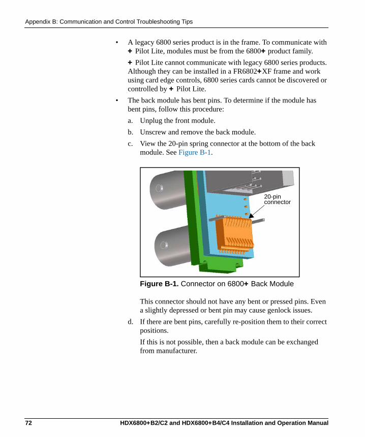
Appendix B: Communication and Control Troubleshooting Tips
• A legacy 6800 series product is in the frame. To communicate with + Pilot Lite, modules must be from the 6800+ product family.+ Pilot Lite cannot communicate with legacy 6800 series products. Although they can be installed in a FR6802+XF frame and work using card edge controls, 6800 series cards cannot be discovered or controlled by + Pilot Lite.
• The back module has bent pins. To determine if the module has bent pins, follow this procedure:a. Unplug the front module. b. Unscrew and remove the back module.c. View the 20-pin spring connector at the bottom of the back
module. See Figure B-1.
Figure B-1. Connector on 6800+ Back Module
This connector should not have any bent or pressed pins. Even a slightly depressed or bent pin may cause genlock issues.
d. If there are bent pins, carefully re-position them to their correct positions. If this is not possible, then a back module can be exchanged from manufacturer.
20-pin connector
72 HDX6800+B2/C2 and HDX6800+B4/C4 Installation and Operation Manual
Appendix B: Communication and Control Troubleshooting Tips
+ Pilot Lite Does Not Find All Modules in FrameIf a discovery is started too soon after frame power-up, + Pilot Lite will not find all the installed modules. Refresh + Pilot Lite (File > Refresh), and ensure that installed modules are fully powered-up before discovery.If a module is plugged into the frame after a discovery, + Pilot Lite will not automatically detect the module. Refresh + Pilot Lite (File > Refresh) to discover the newly installed module.If a legacy 6800 series product is in the frame, + Pilot Lite will not detect it. + Pilot Lite cannot communicate with legacy 6800 series products. Although they can be installed in the FR6802+XF frame and work using card edge controls, they will not be discovered or controlled by + Pilot Lite. For + Pilot Lite to find a module, it must be from the 6800+ product family.
+ Pilot Lite or CCS Software Application Not Responding+ Pilot Lite and a CCS application such as Navigator or Pilot cannot run on the same PC at the same time. Both applications can be installed, but only one can be opened at a time.
+ Pilot Lite Cannot Control a Module Showing in the Control Window
Consider these questions:• Did you physically set the jumper for local control? If so, set this
jumper to the REM position for remote control.• Is the module properly seated in the frame? Check the positioning
of the module in its slot in the frame.• Does the Control window indicate the device is “ready”? The
device may be powered off or disconnected from the network.
HDX6800+B2/C2 and HDX6800+B4/C4 Installation and Operation Manual 73
Appendix B: Communication and Control Troubleshooting Tips
+ Pilot Lite Status Bar Reports ‘Not Ready’+ Pilot Lite reports each device’s connection status in the status bar. If the connection status message reads “Not Ready,” check the following:• Is the module properly seated in the frame? Check the position of
the module in the frame.• Is the frame connected to the network? Check the device’s network
connection.If the status bar still reports no status or “Not Ready” for the frame or device, try restarting + Pilot Lite.
CCS Software Application or Remote Control Panel Does Not Communicate with Module
CCS software applications (such as Pilot, CoPilot, and Navigator) and remote control panels require the purchase and installation of an ICE6800+ module in an FR6802+ frame in order to communicate remotely via Ethernet.
Alarm Query Fails When a Device RebootsWhen you reboot a device connected to your PC, the alarm traffic hitting the network may cause an alarm query request to time out and fail. While the query does not automatically retry, it will post an “Alarm query failed” message to the Diagnostics window.To clear an “Alarm query failed” message, right-click inside the Diagnostics window, and then select Refresh from the resulting context menu.
74 HDX6800+B2/C2 and HDX6800+B4/C4 Installation and Operation Manual
Appendix B: Communication and Control Troubleshooting Tips
Hardware Communication and Control Issues
Frames Fail to Communicate with the PC after a Power Failure
Have you exited the software and restarted since the frame recovered from its power failure? To restore communications between the PC and the frames, ensure that the frames have three or more minutes to recover from the power failure before you exit the application and restart the PC.
Module Does Not Seem to WorkAlthough the following troubleshooting tips may seem obvious, please take the time to ensure the following:• All appropriate rear connections are securely made• The board is securely installed (with no bent pins)• The frame is turned on
Contacting Customer ServiceWe are committed to providing round-the-clock, 24-hour service to our customers around the world. Visit the Support sections of our Web site at www.broadcast.harris.com/leitch for information on how to contact the Customer Service team in your geographical region.
HDX6800+B2/C2 and HDX6800+B4/C4 Installation and Operation Manual 75

Appendix B: Communication and Control Troubleshooting Tips
76 HDX6800+B2/C2 and HDX6800+B4/C4 Installation and Operation Manual
Index
Index to TermsKeywords
AAES format 41alarm query 74alarms 55application not responding 73audience iaudio
balanced 59bit manipulation 63channel dithering 29channel fade rate 29channel word length 29de-embedding 26delay 48dithering 43fade rate 44gain 42invert 42mute 26, 34normal 25output channel 25output rate 26peak 25processing information 25repeat 26sampling frequency 68sampling rate 48silence 25test tones 26
unbalanced 59word length 43, 68
Bback connectors 6
Cc-bit 64CCS software 23, 73changing parameters 30channel dithering 29channel source selection 26channel status 25, 64checksum errors 49compatibility 73connectors 6contacting Leitch customer service 75control LEDs 4, 30control problems 73conventions, writing iiCoPilot 23Copyright information iiCorrecting failed upgrades 21cross-functional parameter changes 27
DDARS input 33DBN errors 33de-embedder 26
HDX6800+B2/C2 and HDX6800+B4/C4 Installation and Operation Manual 77
Index
de-embedding errors 26, 49default parameter settings 31delayed audio 48demux 33demux control group 26description, general 2discovery failure 73dithering audio 43
Eerror correction 49error counters 33extractor handle 4
Ffactory recall 24, 33factory reset 31fade rate 29, 44failure, power 75features 2Firmware updating, modules 17–22frames 12front module 4
Ggain 42general description 2
Hhardware versions 31hex switch 30
IICE6800+ 71input channel feedback 25inputs 2, 6
audio 44specifications 58video standards 33, 44
installed modules 73Installing and removing modules 16invert audio 42
Jjumpers 14
LLEDs 4
control 30module status 52, 54monitoring 52
Leitch customer service, contacting 75Leitch documents, obtaining iilocal control 14, 73
Mmode select rotary switch 4Module
installation and removal 16module not found 73Module software upgrading 17–22module status LEDs 4, 52, 54module, front 4monitoring LEDs 4, 52mute audio 26, 34, 44
NNavigation Properties box 22navigation switch 4, 30Navigator 23network connection 74non-PCM processing 27normal audio 25
78 HDX6800+B2/C2 and HDX6800+B4/C4 Installation and Operation Manual
Index
normal status 51not ready status 73
Oobtaining Leitch documents iioperating notes 24operating temperature 61output audio rate 26outputs 2, 6
source 34specifications 59video 60
Ppackaging 13packing list 13parameters 30, 32PCM processing 27peak audio 25peak status 51Pilot 23+ Pilot Lite 23, 70power consumption 12, 61power failure 75Precautions, safety viProcessing 25Product servicing iiipropagation delay 61
Rreboot device 74rem/loc jumper 14
location 4remote control 14, 73Removing and installing modules 16repeat audio 26restore defaults 31
Returning a product iiirevision history iRoHS compliance iv
SSafety precautions visetting jumpers 14Shipping and unpacking a product iiisignal flow 10silent audio 25, 51Software upgrading 17–22software versions 31Standards
RoHS compliance ivWEEE compliance v
status not ready 73Support documents iiswap audio 44
Ttermination 24test tones 26troubleshooting 69–75
+ Pilot Lite 70general 70
Uu-bit 67unpacking 13Unpacking and shipping a product iiiUpgrading module firmware 17–22user bit 67
Vvalidity bit 25, 67v-bit 25, 67versions, software and hardware 31
HDX6800+B2/C2 and HDX6800+B4/C4 Installation and Operation Manual 79

Index
WWarranty information iiWEEE compliance v
word length 29, 43, 68writing conventions iiwww.broadcast.harris.com/leitch ii
80 HDX6800+B2/C2 and HDX6800+B4/C4 Installation and Operation Manual


Broadcast Communications Division 4393 Digital Way | Mason, OH USA 45040 | Tel: 1 (513) 459 3400
www.broadcast.harris.com
©2006 Harris Corporation
Harris is a registered trademark of Harris Corporation. Trademarks and tradenames are the property of their respective companies.
Customer Service Support
+1 416 445 4032
+1 888 LEITCH-6
+1 888 534 8246


![MAPA TURISMO FERROL 2017:Maquetación 1 · Ruta a Pé | Ruta a Pie | Walking Route [1h30min] Porto de Curuxeiras B4 Arsenal Militar: Sala de Armas B4 Igrexa de San Francisco C4 Capela](https://img.pdfslide.net/doc/110x75/5f49ad5714c2ac2acd69f8d7/mapa-turismo-ferrol-2017maquetacin-1-ruta-a-p-ruta-a-pie-walking-route.jpg)


![INDEX [] 2014.pdf · ACCIAIO B4 O BRONZO B4B MOLD BASE 4 PINS 2 OR 3 PLATES, FIXED PINS C4 AND FIXED BUSHES STEEL B4 OR BRONZE B4B Colonna disassata Moved pin ... 4012 300 200 48](https://img.pdfslide.net/doc/110x75/5f5b2f13f38d9e6f8011bee7/index-2014pdf-acciaio-b4-o-bronzo-b4b-mold-base-4-pins-2-or-3-plates-fixed.jpg)