Embed Size (px)
Citation preview
ISO 9001:2008
www.fanox.com Installation_Guide_SIAB000B0021AA_Rev. 01 1 / 32
INSTALLATION & COMMISIONING GUIDE
SIA-B Self & Dual Power Overcurrent Protection Relay
ISO 9001:2008
www.fanox.com Installation_Guide_SIAB000B0021AA_Rev. 01 2 / 32
1. ..... RECEPTION & INSTALLATION .......................................................................................... 3
1.1. Relay unpacking ............................................................................................................. 3
1.2. Relay verification ............................................................................................................ 3
1.3. Powering the relay up .................................................................................................... 4
1.4. Relay intallation .............................................................................................................. 6
1.5. Relay rear part ................................................................................................................ 6
1.6. Connection diagram ....................................................................................................... 7
2. ..... USER INTERFACE .............................................................................................................. 8
2.1. Relay front part ............................................................................................................... 8
2.2. Bistable magnetic indicator (Flag) ............................................................................... 8
2.3. LED indicators ................................................................................................................ 8
2.4. How to install SICOM software ..................................................................................... 8
2.5. Setting-up the session: Password and access levels ................................................ 9
3. ..... FUNCTIONAL DIAGRAM .................................................................................................... 9
4. ..... TECHNICAL SPECIFICATIONS ........................................................................................ 10
4.1. IEC60255-151 Curves ................................................................................................... 12
4.2. IEEE Curves .................................................................................................................. 12
5. ..... SPECIFIC CURRENT TRANSFORMERS ......................................................................... 13
5.1. Test Winding ................................................................................................................. 14
6. ..... OPENING MECHANISM .................................................................................................... 14
7. ..... PROGRAMABLE LOGIC CONTROL ................................................................................ 15
8. ..... FLOWCHART ..................................................................................................................... 16
8.1. Test menu...................................................................................................................... 16
8.2. Direct Access ................................................................................................................ 16
8.3. Menus ............................................................................................................................ 18
9. ..... COMMISIONING ................................................................................................................ 24
9.1. Thermal resistance ....................................................................................................... 24
9.2. Self powering ................................................................................................................ 26
9.3. Measurements .............................................................................................................. 27
9.4. Protection functions .................................................................................................... 27
10. ... SIAB000B0021AA REGISTRY .......................................................................................... 30
ISO 9001:2008
www.fanox.com Installation_Guide_SIAB000B0021AA_Rev. 01 3 / 32
1. RECEPTION & INSTALLATION
1.1. Relay unpacking
Previously to any handling action, confirm that relay carton box is in good conditions, no broken or damaged due to external manipulation or during storing or moving process. If packing is correct, proceed to unpack and you should find following element:
• SIAB Electronic protection relay.
• User Guide.
• Testing protocol.
Testing protocol is a certificate that relay has passed all factory testing process with correct results.
In case some fault is detected, consider putting into quarantine period the relay and contact Fanox for further instructions.
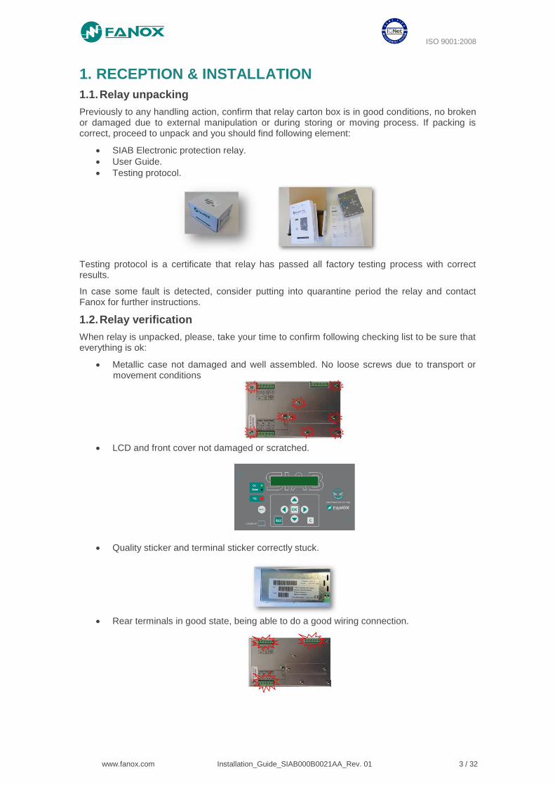
1.2. Relay verification
When relay is unpacked, please, take your time to confirm following checking list to be sure that everything is ok:
• Metallic case not damaged and well assembled. No loose screws due to transport or movement conditions
• LCD and front cover not damaged or scratched.
• Quality sticker and terminal sticker correctly stuck.
• Rear terminals in good state, being able to do a good wiring connection.
ISO 9001:2008
www.fanox.com Installation_Guide_SIAB000B0021AA_Rev. 01 4 / 32
1.3. Powering the relay up
Thanks to the external battery KITCOM the powering and adjusting process of the relay is very easy and it allows the user to test the relay.
The power comes from two AA batteries (IEC LR06) of 1.5 Volts placed at the bottom of the kitcom. The equipment has a small Dc/Dc power supply that raises the voltage till the required 5 volts to operate the equipment and that is plugged into the front USB communications port (KITCOM).
Once the KITCom is connected, the relay will be switched on and a led on the left of the relay (led on) will blink indicating the relay is powered on through an external battery (KITCOM).
The relay is totally maintenance free. This is, there is no need of batteries to log events and fault reports and there is no need of batteries to maintain date and time.
NOTE: Date and time must be correctly set the first time the relay is operative and energy must be kept at least “1 hour” to maintain the RTC for 72 hours once the energy is lost.
Besides, the possibility of using external battery power, together with the possibility of activating the trip contact from the test menu, allows the trip circuit to be tested before the transformation center is powered up. So, the KITCOM is useful for cases like commissioning operations, discharges and repairs to the transformation center.
Using battery power does not block the USB communications port, as it can be used simultaneously.
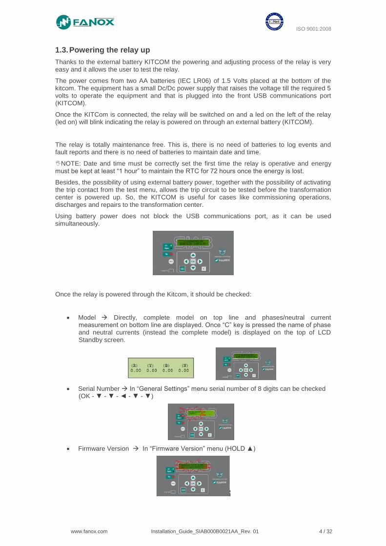
Once the relay is powered through the Kitcom, it should be checked:
• Model Directly, complete model on top line and phases/neutral current measurement on bottom line are displayed. Once “C” key is pressed the name of phase and neutral currents (instead the complete model) is displayed on the top of LCD Standby screen.
• Serial Number In “General Settings” menu serial number of 8 digits can be checked (OK - ▼ - ▼ - ◄ - ▼ - ▼)
• Firmware Version In “Firmware Version” menu (HOLD ▲)
ISO 9001:2008
www.fanox.com Installation_Guide_SIAB000B0021AA_Rev. 01 5 / 32
1.3.1. Keypad & LCD
• Use KEYPAD to ensure that all the push-buttons work correctly (no difficulties while pushing them, check out if the relay reacts by pushing each of the buttons)
• Use KEYPAD to enter in the relay´s menu and make sure that no text is lost while going from one menu to another.
• Follow the sequence: Left ◄, Down ▼, Right ►, Up ▲, OK, C and RESET and the following screen should be displayed:
• If the contrast of the LCD is ot the correct one, enter to “CONTRAST” menu by holding “◄” for 3 seconds. Then, change it by using up and dwon buttons to increase or decrease the contrast.
1.3.2. Test menu
NOTE: When performing test menu, protection won´t be available and it will be possible to open circuit breaker. Only authorized personnel can do this job.
Press ◄,▼,► sequentially and hold OK. The relay will ask for the password “5555” to enter to the test menu (or customer password if default “5555” has been modified).
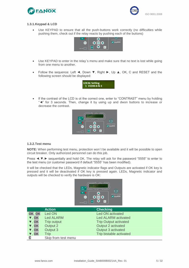
It will be checked that the LEDs, Magnetic indicator flags and Outputs are activated if OK key is pressed and it will be deactivated if OK key is pressed again. LEDs, Magnetic indicator and outputs will be checked to verify the hardware is OK:
Action Checking
OK, OK Led ON Led ON activated ▼, OK Led ALARM Led ALARM activated ▼, OK Trip output Trip Output activated ▼, OK Output 2 Output 2 activated ▼, OK Output 3 Output 3 activated ▼, OK Trip Trip bistable activated C Skip from test menu
ISO 9001:2008
www.fanox.com Installation_Guide_SIAB000B0021AA_Rev. 01 6 / 32
1.4. Relay intallation
To fix the relay to the switchgear, use default holes in front of relay with appropriate fixing system. Do not manipulate relay to fix it on the switchgear.
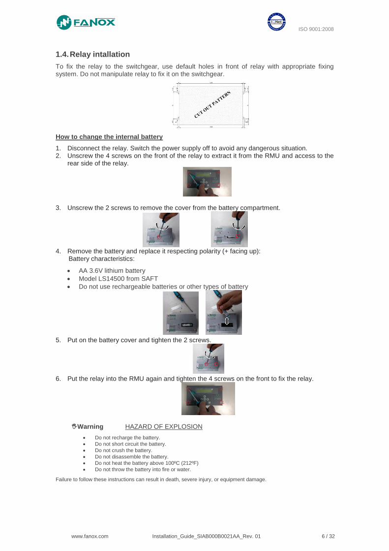
How to change the internal battery
1. Disconnect the relay. Switch the power supply off to avoid any dangerous situation. 2. Unscrew the 4 screws on the front of the relay to extract it from the RMU and access to the
rear side of the relay.
3. Unscrew the 2 screws to remove the cover from the battery compartment.
4. Remove the battery and replace it respecting polarity (+ facing up):
Battery characteristics:
• AA 3.6V lithium battery
• Model LS14500 from SAFT
• Do not use rechargeable batteries or other types of battery
5. Put on the battery cover and tighten the 2 screws.
6. Put the relay into the RMU again and tighten the 4 screws on the front to fix the relay.
Warning HAZARD OF EXPLOSION
• Do not recharge the battery.
• Do not short circuit the battery.
• Do not crush the battery.
• Do not disassemble the battery.
• Do not heat the battery above 100ºC (212ºF)
• Do not throw the battery into fire or water.
Failure to follow these instructions can result in death, severe injury, or equipment damage.
ISO 9001:2008
www.fanox.com Installation_Guide_SIAB000B0021AA_Rev. 01 7 / 32
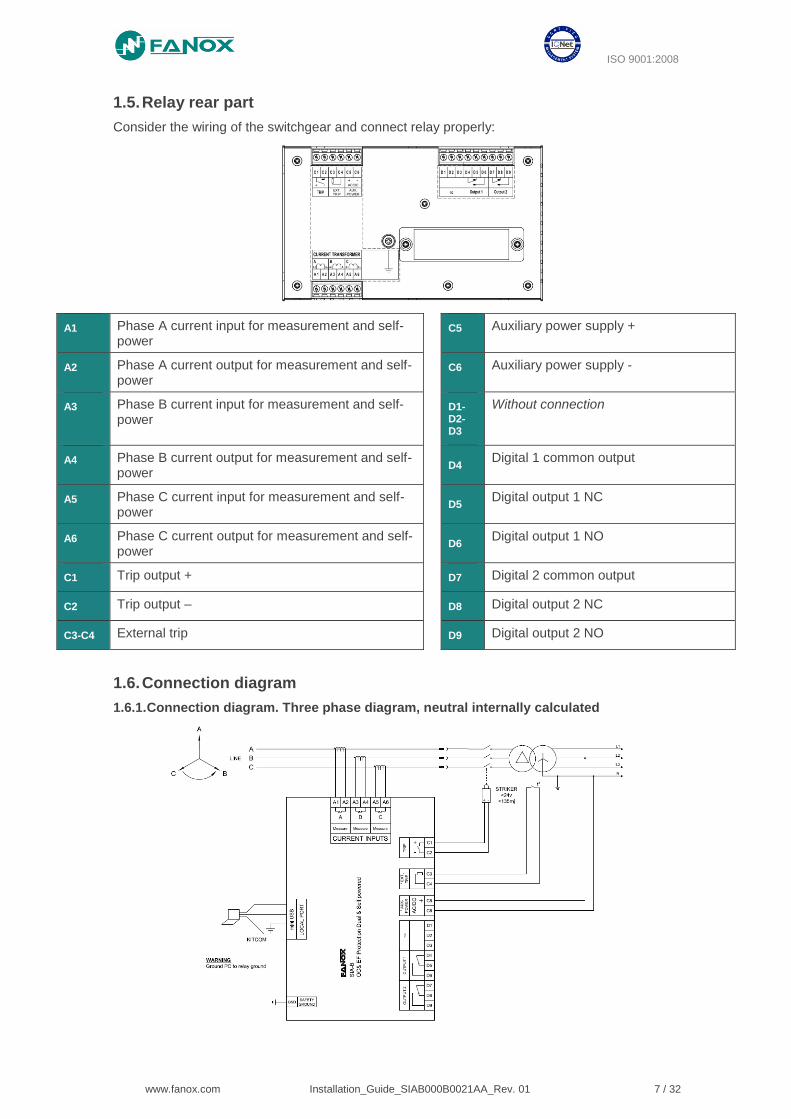
1.5. Relay rear part
Consider the wiring of the switchgear and connect relay properly:
A1 Phase A current input for measurement and self-power
C5 Auxiliary power supply +
A2 Phase A current output for measurement and self-power
C6 Auxiliary power supply -
A3 Phase B current input for measurement and self-power
D1-D2-D3
Without connection
A4 Phase B current output for measurement and self-power
D4
Digital 1 common output
A5 Phase C current input for measurement and self-power
D5
Digital output 1 NC
A6 Phase C current output for measurement and self-power
D6
Digital output 1 NO
C1 Trip output + D7 Digital 2 common output
C2 Trip output – D8 Digital output 2 NC
C3-C4 External trip D9 Digital output 2 NO
1.6. Connection diagram
1.6.1. Connection diagram. Three phase diagram, neutral internally calculated
ISO 9001:2008
www.fanox.com Installation_Guide_SIAB000B0021AA_Rev. 01 8 / 32
2. USER INTERFACE
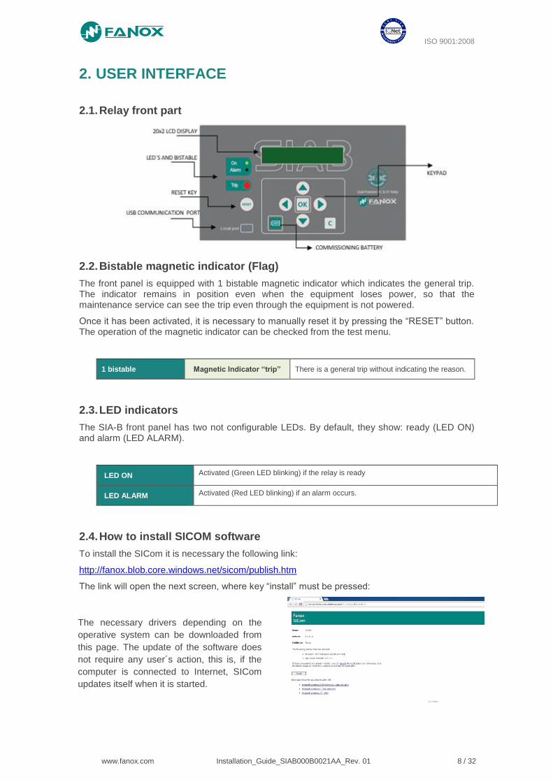
2.1. Relay front part
2.2. Bistable magnetic indicator (Flag)
The front panel is equipped with 1 bistable magnetic indicator which indicates the general trip. The indicator remains in position even when the equipment loses power, so that the maintenance service can see the trip even through the equipment is not powered.
Once it has been activated, it is necessary to manually reset it by pressing the “RESET” button. The operation of the magnetic indicator can be checked from the test menu.
1 bistable Magnetic Indicator “trip” There is a general trip without indicating the reason.
2.3. LED indicators
The SIA-B front panel has two not configurable LEDs. By default, they show: ready (LED ON) and alarm (LED ALARM).
LED ON Activated (Green LED blinking) if the relay is ready
LED ALARM Activated (Red LED blinking) if an alarm occurs.
2.4. How to install SICOM software
To install the SICom it is necessary the following link:
http://fanox.blob.core.windows.net/sicom/publish.htm
The link will open the next screen, where key “install” must be pressed:
The necessary drivers depending on the
operative system can be downloaded from
this page. The update of the software does
not require any user´s action, this is, if the
computer is connected to Internet, SICom
updates itself when it is started.

ISO 9001:2008
www.fanox.com Installation_Guide_SIAB000B0021AA_Rev. 01 9 / 32
2.5. Setting-up the session: Password and access levels
Users must identify themselves with a password to start communications and to change the equipment settings or configuration using the HMI. Depending on the access level, it may or may not be possible to perform the operations shown on the table below.
ACCESS LEVEL Read-only permission:
Status and measurements
Settings
Events
Permission to:
Change settings
Download and Delete the Events buffer
Permission to:
Execute Commands
Permission to:
Change Configuration
Permission to Change
Protected Settings
1 YES YES NO NO YES
2 YES YES NO NO NO
3 YES NO YES NO NO
4 YES YES YES NO NO
5 YES YES YES YES NO
Four passwords and their associated levels of access are set up when the equipment is configured using the SIcom program. By default, the equipment is programmed with the following passwords and their associated levels:
PASSWORD ACCESS LEVEL
2222 2
3333 3
4444 4
5555 5
3. FUNCTIONAL DIAGRAM
ISO 9001:2008
www.fanox.com Installation_Guide_SIAB000B0021AA_Rev. 01 10 / 32
4. TECHNICAL SPECIFICATIONS
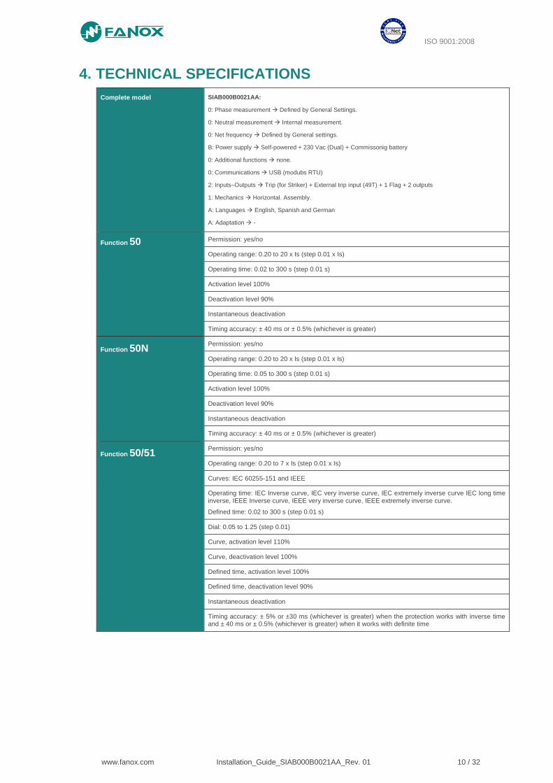
Complete model SIAB000B0021AA:
0: Phase measurement Defined by General Settings.
0: Neutral measurement Internal measurement.
0: Net frequency Defined by General settings.
B: Power supply Self-powered + 230 Vac (Dual) + Commissonig battery
0: Additional functions none.
0: Communications USB (modubs RTU)
2: Inputs–Outputs Trip (for Striker) + External trip input (49T) + 1 Flag + 2 outputs
1: Mechanics Horizontal. Assembly.
A: Languages English, Spanish and German
A: Adaptation -
Function 50 Permission: yes/no
Operating range: 0.20 to 20 x Is (step 0.01 x Is)
Operating time: 0.02 to 300 s (step 0.01 s)
Activation level 100%
Deactivation level 90%
Instantaneous deactivation
Timing accuracy: ± 40 ms or ± 0.5% (whichever is greater)
Function 50N Permission: yes/no
Operating range: 0.20 to 20 x Is (step 0.01 x Is)
Operating time: 0.05 to 300 s (step 0.01 s)
Activation level 100%
Deactivation level 90%
Instantaneous deactivation
Timing accuracy: ± 40 ms or ± 0.5% (whichever is greater)
Function 50/51 Permission: yes/no
Operating range: 0.20 to 7 x Is (step 0.01 x Is)
Curves: IEC 60255-151 and IEEE
Operating time: IEC Inverse curve, IEC very inverse curve, IEC extremely inverse curve IEC long time inverse, IEEE Inverse curve, IEEE very inverse curve, IEEE extremely inverse curve.
Defined time: 0.02 to 300 s (step 0.01 s)
Dial: 0.05 to 1.25 (step 0.01)
Curve, activation level 110%
Curve, deactivation level 100%
Defined time, activation level 100%
Defined time, deactivation level 90%
Instantaneous deactivation
Timing accuracy: ± 5% or ±30 ms (whichever is greater) when the protection works with inverse time and ± 40 ms or ± 0.5% (whichever is greater) when it works with definite time
ISO 9001:2008
www.fanox.com Installation_Guide_SIAB000B0021AA_Rev. 01 11 / 32
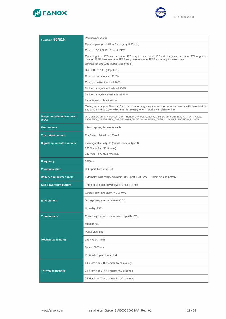
Function 50/51N Permission: yes/no
Operating range: 0.20 to 7 x Is (step 0.01 x Is)
Curves: IEC 60255-151 and IEEE
Operating time: IEC Inverse curve, IEC very inverse curve, IEC extremely inverse curve IEC long time inverse, IEEE Inverse curve, IEEE very inverse curve, IEEE extremely inverse curve.
Defined time: 0.02 to 300 s (step 0.01 s)
Dial: 0.05 to 1.25 (step 0.01)
Curve, activation level 110%
Curve, deactivation level 100%
Defined time, activation level 100%
Defined time, deactivation level 90%
Instantaneous deactivation
Timing accuracy: ± 5% or ±30 ms (whichever is greater) when the protection works with inverse time and ± 40 ms or ± 0.5% (whichever is greater) when it works with definite time
Programmable logic control (PLC)
OR4, OR4_LATCH, OR4_PULSES, OR4_TIMERUP, OR4_PULSE, NOR4, AND4_LATCH, NOR4_TIMERUP, NOR4_PULSE, AND4, AND4_PULSES, AND4_TIMERUP, AND4_PULSE, NAND4, NAND4_TIMERUP, NAND4_PULSE, NOR4_PULSES
Fault reports 4 fault reports, 24 events each
Trip output contact For Striker: 24 Vdc – 135 mJ
Signalling outputs contacts 2 configurable outputs (output 2 and output 3):
220 Vdc – 8 A (30 W max)
250 Vac – 8 A (62,5 VA max)
Frequency 50/60 Hz
Communication USB port: Modbus RTU
Battery and power supply Externally, with adapter (Kitcom) USB port + 230 Vac + Commisioning battery
Self-power from current Three phase self-power level: I > 0,4 x Is min
Environment
Operating temperature: -40 to 70ºC
Storage temperature: -40 to 80 ºC
Humidity: 95%
Transformers Power supply and measurement specific CTs
Mechanical features
Metallic box
Panel Mounting
185.8x124.7 mm
Depth: 59.7 mm
IP-54 when panel mounted
Thermal resistance
10 x Ismin or 2´85xIsmax: Continuously
20 x Ismin or 5´7 x Ismax for 60 seconds
25 xIsmin or 7´14 x Ismax for 10 seconds.
ISO 9001:2008
www.fanox.com Installation_Guide_SIAB000B0021AA_Rev. 01 12 / 32
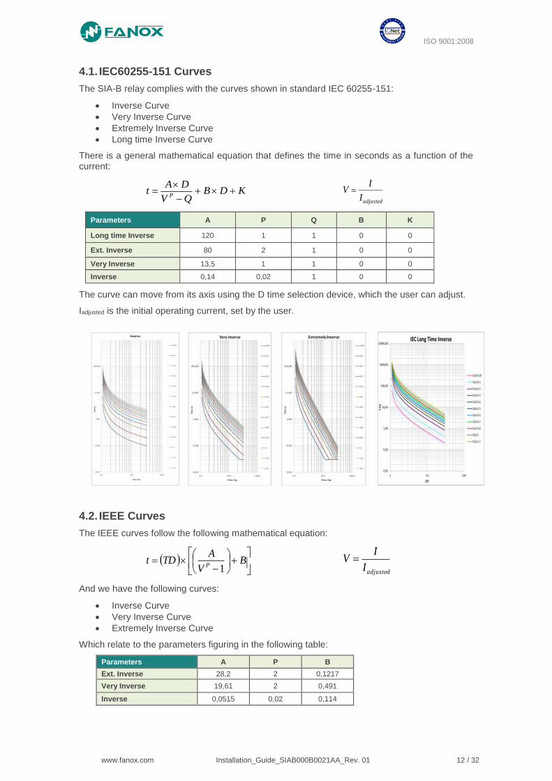
4.1. IEC60255-151 Curves
The SIA-B relay complies with the curves shown in standard IEC 60255-151:
• Inverse Curve
• Very Inverse Curve
• Extremely Inverse Curve
• Long time Inverse Curve
There is a general mathematical equation that defines the time in seconds as a function of the current:
KDBQV
DAt
P
adjustedI
IV
Parameters A P Q B K
Long time Inverse 120 1 1 0 0
Ext. Inverse 80 2 1 0 0
Very Inverse 13,5 1 1 0 0
Inverse 0,14 0,02 1 0 0
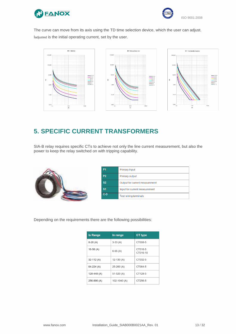
The curve can move from its axis using the D time selection device, which the user can adjust.
Iadjusted is the initial operating current, set by the user.
4.2. IEEE Curves
The IEEE curves follow the following mathematical equation:
B
V
ATDt
P 1 adjustedI
IV
And we have the following curves:
• Inverse Curve
• Very Inverse Curve
• Extremely Inverse Curve
Which relate to the parameters figuring in the following table:
Parameters A P B
Ext. Inverse 28,2 2 0,1217
Very Inverse 19,61 2 0,491
Inverse 0,0515 0,02 0,114
ISO 9001:2008
www.fanox.com Installation_Guide_SIAB000B0021AA_Rev. 01 13 / 32
The curve can move from its axis using the TD time selection device, which the user can adjust.
Iadjusted is the initial operating current, set by the user.
5. SPECIFIC CURRENT TRANSFORMERS
SIA-B relay requires specific CTs to achieve not only the line current measurement, but also the power to keep the relay switched on with tripping capability.
Depending on the requirements there are the following possibilities:
ISO 9001:2008
www.fanox.com Installation_Guide_SIAB000B0021AA_Rev. 01 14 / 32
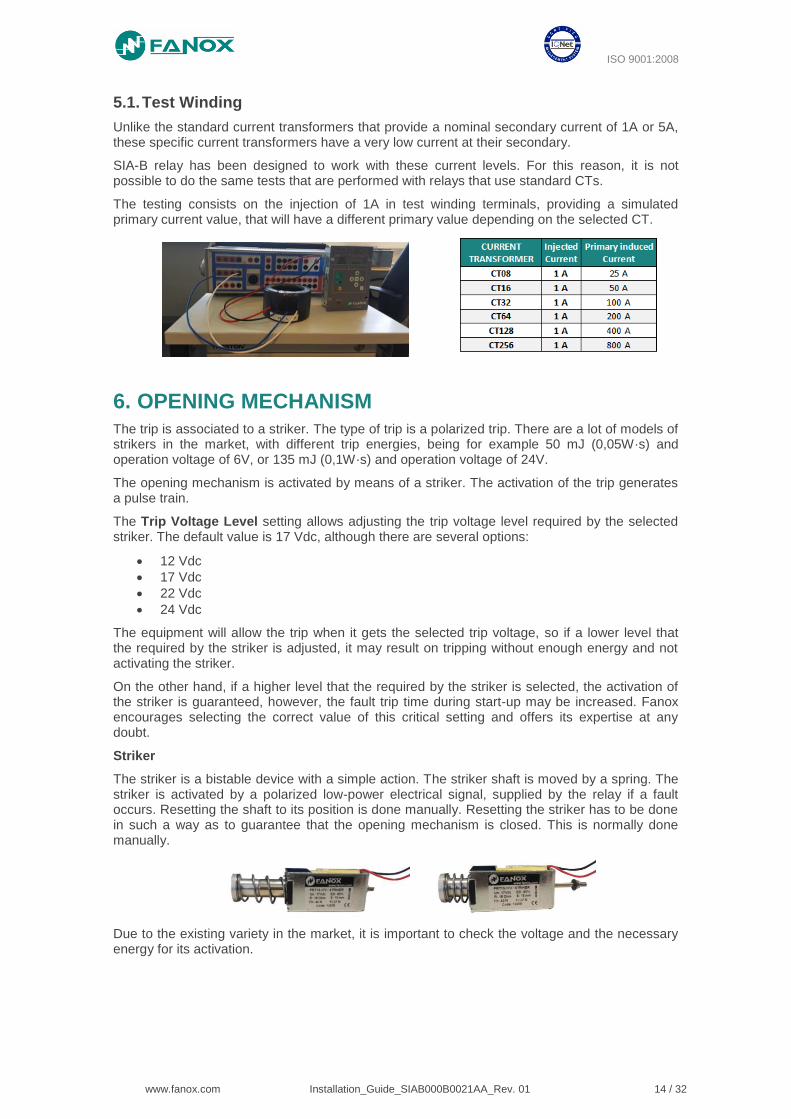
5.1. Test Winding
Unlike the standard current transformers that provide a nominal secondary current of 1A or 5A, these specific current transformers have a very low current at their secondary.
SIA-B relay has been designed to work with these current levels. For this reason, it is not possible to do the same tests that are performed with relays that use standard CTs.
The testing consists on the injection of 1A in test winding terminals, providing a simulated primary current value, that will have a different primary value depending on the selected CT.
6. OPENING MECHANISM
The trip is associated to a striker. The type of trip is a polarized trip. There are a lot of models of strikers in the market, with different trip energies, being for example 50 mJ (0,05W·s) and operation voltage of 6V, or 135 mJ (0,1W·s) and operation voltage of 24V.
The opening mechanism is activated by means of a striker. The activation of the trip generates a pulse train.
The Trip Voltage Level setting allows adjusting the trip voltage level required by the selected striker. The default value is 17 Vdc, although there are several options:
• 12 Vdc
• 17 Vdc
• 22 Vdc
• 24 Vdc
The equipment will allow the trip when it gets the selected trip voltage, so if a lower level that the required by the striker is adjusted, it may result on tripping without enough energy and not activating the striker.
On the other hand, if a higher level that the required by the striker is selected, the activation of the striker is guaranteed, however, the fault trip time during start-up may be increased. Fanox encourages selecting the correct value of this critical setting and offers its expertise at any doubt.
Striker
The striker is a bistable device with a simple action. The striker shaft is moved by a spring. The striker is activated by a polarized low-power electrical signal, supplied by the relay if a fault occurs. Resetting the shaft to its position is done manually. Resetting the striker has to be done in such a way as to guarantee that the opening mechanism is closed. This is normally done manually.
Due to the existing variety in the market, it is important to check the voltage and the necessary energy for its activation.
ISO 9001:2008
www.fanox.com Installation_Guide_SIAB000B0021AA_Rev. 01 15 / 32
7. PROGRAMABLE LOGIC CONTROL
Physical outputs are the real outputs of the Device. SIA-B has a trip output (not configurable) and up to 2 digital outputs (Output 2 and Output 3).
All the outputs (Physical outputs) are the result of a PROGRAMMABLE LOGIC CONTROL which can be configured from HMI or from SICom software.
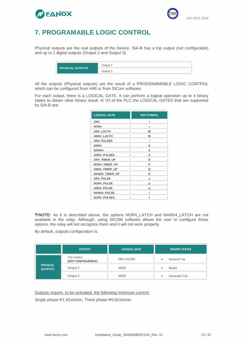
For each output, there is a LOGICAL GATE. It can perform a logical operation up to 4 binary states to obtain other binary result. In V3 of the PLC the LOGICAL GATES that are supported by SIA-B are:
NOTE: As it is described above, the options NOR4_LATCH and NAND4_LATCH are not available in the relay. Although, using SICOM software allows the user to configure these options, the relay will not recognize them and it will not work properly.
By default, outputs configuration is:
OUTPUT LOGICAL GATE BINARY STATES
PHYSICAL OUTPUTS
Trip output (NOT CONFIGURABLE)
OR4_PULSES • General Trip
Output 2 AND4 • Ready
Output 3 AND4 • Generalal Trip
Outputs require, to be activated, the following mínimum current:
Single phase1.62xIsmin. Three phase0.62xIsmin
PHYSICAL OUTPUTS Output 2
Output 3
LOGICAL GATE HMI SYMBOL
OR4 +
NOR4
OR4_LACTH Ю
AND4_LACTH Φ
OR4_PULSES ⌠
AND4 &
NAND4 §
AND4_PULSES $
OR4_TIMER_UP O
NOR4_TIMER_UP P
AND4_TIMER_UP Q
NAND4_TIMER_UP R
OR4_PULSE o
NOR4_PULSE p
AND4_PULSE q
NAND4_PULSE r
NOR4_PULSES t
ISO 9001:2008
www.fanox.com Installation_Guide_SIAB000B0021AA_Rev. 01 16 / 32
8. FLOWCHART
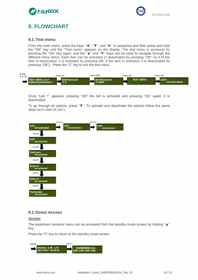
8.1. Test menu
From the main menu, press the keys “◄”, “▼”, and “►” in sequence and then press and hold the "OK" key until the "Test menu" appears on the display. The test menu is accessed by pressing the "OK" key again, and the “▲” and “▼” keys can be used to navigate through the different menu items. Each item can be activated or deactivated by pressing "OK" on it (if the item is deactivated, it is activated by pressing OK; if the item is activated, it is deactivated by pressing “OK”). Press the “C” key to exit the test menu.
Once “Led 1” appears, pressing “OK” the led is activated and pressing “OK” again, it is deactivated.
To go through all options, press “▼”. To activate and deactivate the options follow the same steps as in case of Led 1.
8.2. Direct Access
Version
The equipment versions menu can be accessed from the standby mode screen by holding “▲” key.
Press the “C” key to return to the standby mode screen.

ISO 9001:2008
www.fanox.com Installation_Guide_SIAB000B0021AA_Rev. 01 17 / 32
Date and time
Press the “►” key from the standby mode screen to access to date and time menu
Press the “OK” key to access the date-time modification screen. Use the “►” and “◄” keys to position the cursor over the digit that you want to change, and assign a value to this digit using the “▲” and “▼” keys. Once the date-time has been entered, press “OK” to change the equipment date.
Press the “C” key to return to the standby mode screen.
Contrast
Hold “◄” key from standby menu to access to Contrast menu. Use the “▲” and “▼” keys to select the desired value.
Press the “C” key to return to the standby mode screen.
Communication parameters
Hold “▼” key from standby menu to access to communication parameters menu.
Press the “C” key to return to the standby mode screen.
ISO 9001:2008
www.fanox.com Installation_Guide_SIAB000B0021AA_Rev. 01 18 / 32
8.3. Menus
8.3.1. Measurements menu
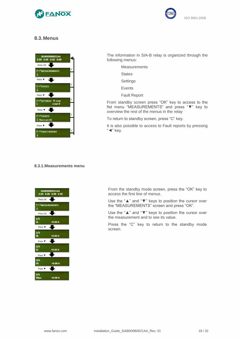
The information in SIA-B relay is organized through the following menus:
Measurements
States
Settings
Events
Fault Report
From standby screen press “OK” key to access to the fist menu “MEASUREMENTS” and press “▼” key to overview the rest of the menus in the relay
To return to standby screen, press “C” key.
It is also possible to access to Fault reports by pressing “◄” key.
From the standby mode screen, press the “OK” key to access the first line of menus.
Use the “▲” and “▼” keys to position the cursor over the “MEASUREMENTS” screen and press “OK”.
Use the “▲” and “▼” keys to position the cursor over the measurement and to see its value.
Press the “C” key to return to the standby mode screen.
ISO 9001:2008
www.fanox.com Installation_Guide_SIAB000B0021AA_Rev. 01 19 / 32
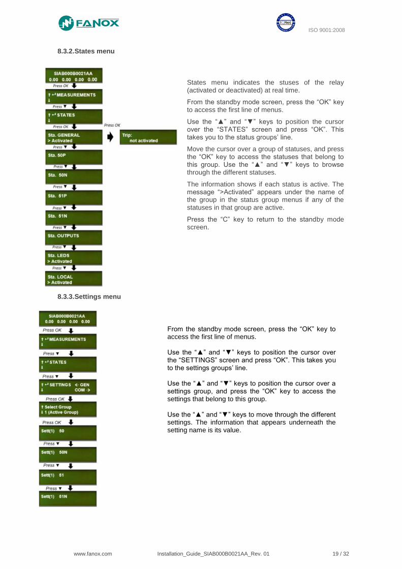
8.3.2. States menu
8.3.3. Settings menu
From the standby mode screen, press the “OK” key to access the first line of menus. Use the “▲” and “▼” keys to position the cursor over the “SETTINGS” screen and press “OK”. This takes you to the settings groups’ line. Use the “▲” and “▼” keys to position the cursor over a settings group, and press the “OK” key to access the settings that belong to this group. Use the “▲” and “▼” keys to move through the different settings. The information that appears underneath the setting name is its value.
States menu indicates the stuses of the relay (activated or deactivated) at real time.
From the standby mode screen, press the “OK” key to access the first line of menus.
Use the “▲” and “▼” keys to position the cursor over the “STATES” screen and press “OK”. This takes you to the status groups’ line.
Move the cursor over a group of statuses, and press the “OK” key to access the statuses that belong to this group. Use the “▲” and “▼” keys to browse through the different statuses.
The information shows if each status is active. The message “>Activated” appears under the name of the group in the status group menus if any of the statuses in that group are active.
Press the “C” key to return to the standby mode screen.
ISO 9001:2008
www.fanox.com Installation_Guide_SIAB000B0021AA_Rev. 01 20 / 32
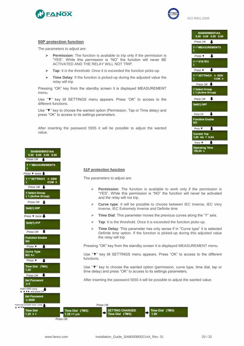
50P protection function
The parameters to adjust are:
➢ Permission: The function is available to trip only if the permission is “YES”. While this permission is “NO” the function will never BE ACTIVATED AND THE RELAY WILL NOT TRIP.
➢ Tap: It is the threshold. Once it is exceeded the function picks-up.
➢ Time Delay: If the function is picked-up during the adjusted value the relay will trip
Pressing “OK” key from the standby screen it is displayed MEASUREMENT menu.
Use “▼” key till SETTINGS menu appears. Press “OK” to access to the different functions.
Use “▼” key to choose the wanted option (Permission, Tap or Time delay) and press “OK” to access to its settings parameters.
After inserting the password 5555 it will be possible to adjust the wanted value.
51P protection function The parameters to adjust are:
➢ Permission: The function is available to work only if the permission is “YES”. While this permission is “NO” the function will never be activated and the relay will not trip.
➢ Curve type: It will be possible to choose between IEC Inverse, IEC Very inverse, IEC Extremely Inverse and Definite time
➢ Time Dial: This parameter moves the previous curves along the “Y” axis.
➢ Tap: It is the threshold. Once it is exceeded the function picks-up.
➢ Time Delay: This parameter has only sense if in “Curve type” it is selected Definite time option. If the function is picked-up during this adjusted value the relay will trip
Pressing “OK” key from the standby screen it is displayed MEASUREMENT menu. Use “▼” key till SETTINGS menu appears. Press “OK” to access to the different functions. Use “▼” key to choose the wanted option (permission, curve type, time dial, tap or time delay) and press “OK” to access to its settings parameters. After inserting the password 5555 it will be possible to adjust the wanted value.

ISO 9001:2008
www.fanox.com Installation_Guide_SIAB000B0021AA_Rev. 01 21 / 32
General settings
From the standby mode screen, press the “OK” key to access the first line of menus. Use the “▲” and “▼” keys to position the cursor over the “SETTINGS” screen. Press the “◄” key to access the general settings from the "SETTINGS" screen.
The general setting "Equipment name" can be viewed from the HMI, but it can only be modified by using the SICom program.
The “CT type” and the “Nominal Current” general settings, depends on which specific CT will be used in the application. For example: if a CT016 is used, the “Nominal Current” would be the nominal current of the installation (NOTE: the installation nominal current value must be inside the range os the CT´s working range).
The frequency is also selected by general settings.
How to set CT type
Pressing “OK” key from the standby screen it is displayed MEASUREMENT menu.
Use “▼” key till SETTINGS menu appears. Pressing “◄” key it is accessed to GENERAL settings.
Use “▼” key to overview the options and press “OK” when “CT type” option appears.
After inserting the password 5555 it will be possible to adjust the wanted value
ISO 9001:2008
www.fanox.com Installation_Guide_SIAB000B0021AA_Rev. 01 22 / 32
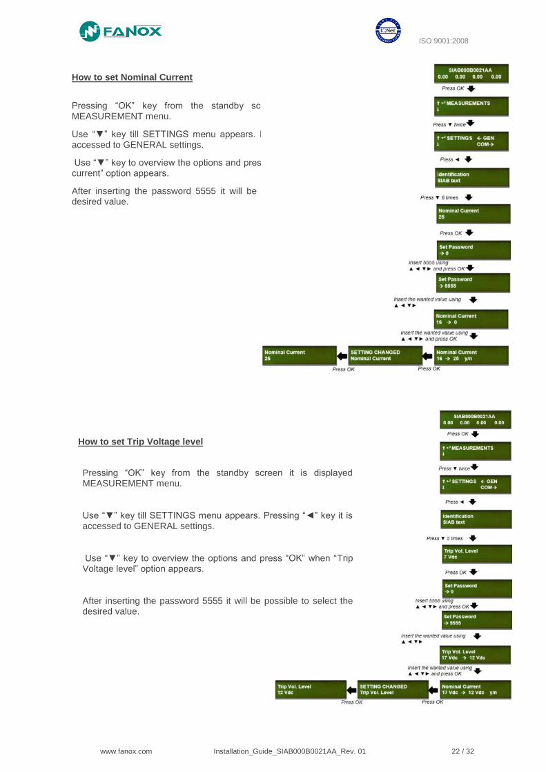
How to set Trip Voltage level
How to set Nominal Current
Pressing “OK” key from the standby screen it is displayed MEASUREMENT menu.
Use “▼” key till SETTINGS menu appears. Pressing “◄” key it is accessed to GENERAL settings.
Use “▼” key to overview the options and press “OK” when “Nominal current” option appears.
After inserting the password 5555 it will be possible to select the desired value.
Pressing “OK” key from the standby screen it is displayed MEASUREMENT menu.
Use “▼” key till SETTINGS menu appears. Pressing “◄” key it is accessed to GENERAL settings.
Use “▼” key to overview the options and press “OK” when “Trip Voltage level” option appears.
After inserting the password 5555 it will be possible to select the desired value.
ISO 9001:2008
www.fanox.com Installation_Guide_SIAB000B0021AA_Rev. 01 23 / 32
8.3.4. Events menu
How to delete the events
8.3.5. Fault reports menu
How to delete the fault reports
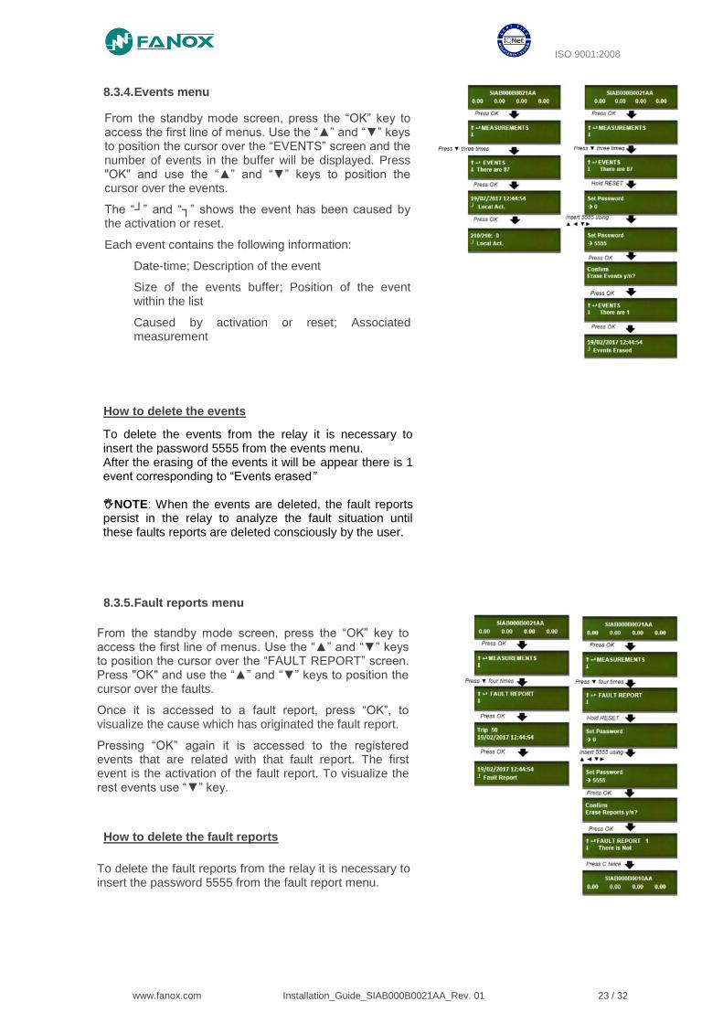
From the standby mode screen, press the “OK” key to access the first line of menus. Use the “▲” and “▼” keys to position the cursor over the “EVENTS” screen and the number of events in the buffer will be displayed. Press "OK" and use the “▲” and “▼” keys to position the cursor over the events.
The “┘” and “┐” shows the event has been caused by the activation or reset.
Each event contains the following information:
Date-time; Description of the event
Size of the events buffer; Position of the event within the list
Caused by activation or reset; Associated measurement
To delete the events from the relay it is necessary to insert the password 5555 from the events menu. After the erasing of the events it will be appear there is 1 event corresponding to “Events erased” NOTE: When the events are deleted, the fault reports persist in the relay to analyze the fault situation until these faults reports are deleted consciously by the user.
From the standby mode screen, press the “OK” key to access the first line of menus. Use the “▲” and “▼” keys to position the cursor over the “FAULT REPORT” screen. Press "OK" and use the “▲” and “▼” keys to position the cursor over the faults.
Once it is accessed to a fault report, press “OK”, to visualize the cause which has originated the fault report.
Pressing “OK” again it is accessed to the registered events that are related with that fault report. The first event is the activation of the fault report. To visualize the rest events use “▼” key.
To delete the fault reports from the relay it is necessary to insert the password 5555 from the fault report menu.
ISO 9001:2008
www.fanox.com Installation_Guide_SIAB000B0021AA_Rev. 01 24 / 32
9. COMMISIONING
9.1. Thermal resistance
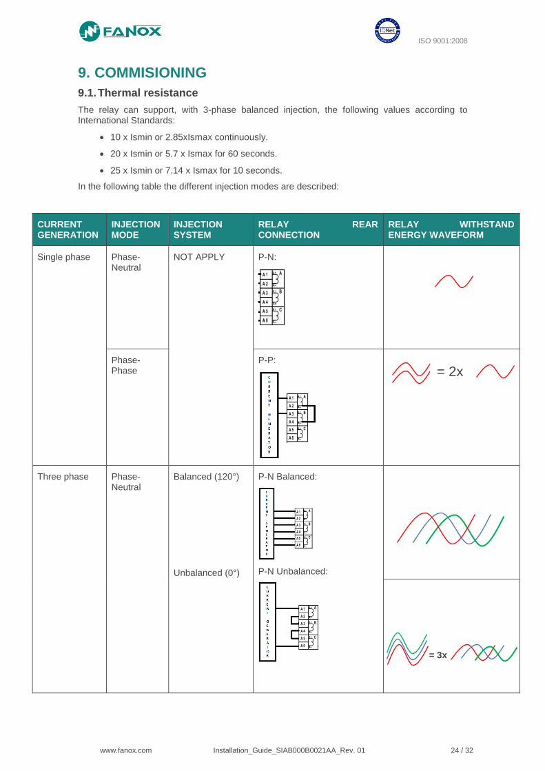
The relay can support, with 3-phase balanced injection, the following values according to International Standards:
• 10 x Ismin or 2.85xIsmax continuously.
• 20 x Ismin or 5.7 x Ismax for 60 seconds.
• 25 x Ismin or 7.14 x Ismax for 10 seconds.
In the following table the different injection modes are described:
CURRENT GENERATION
INJECTION MODE
INJECTION SYSTEM
RELAY REAR CONNECTION
RELAY WITHSTAND ENERGY WAVEFORM
Single phase Phase-Neutral
NOT APPLY P-N:
Phase-Phase
P-P:
Three phase Phase-Neutral
Balanced (120°)
Unbalanced (0°)
P-N Balanced:
P-N Unbalanced:
= 2x
= 3x
ISO 9001:2008
www.fanox.com Installation_Guide_SIAB000B0021AA_Rev. 01 25 / 32
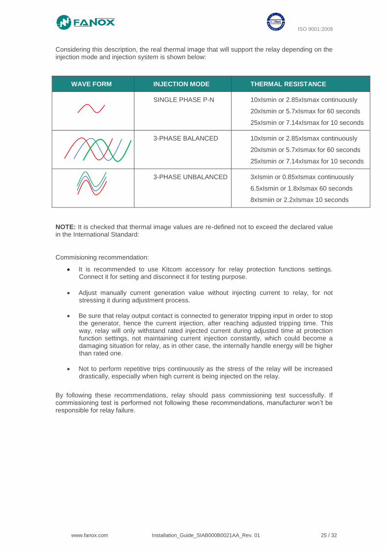
Considering this description, the real thermal image that will support the relay depending on the injection mode and injection system is shown below:
WAVE FORM INJECTION MODE THERMAL RESISTANCE
SINGLE PHASE P-N 10xIsmin or 2.85xIsmax continuously
20xIsmin or 5.7xIsmax for 60 seconds
25xIsmin or 7.14xIsmax for 10 seconds
3-PHASE BALANCED 10xIsmin or 2.85xIsmax continuously
20xIsmin or 5.7xIsmax for 60 seconds
25xIsmin or 7.14xIsmax for 10 seconds
3-PHASE UNBALANCED 3xIsmin or 0.85xIsmax continuously
6.5xIsmin or 1.8xIsmax 60 seconds
8xIsmiin or 2.2xIsmax 10 seconds
NOTE: It is checked that thermal image values are re-defined not to exceed the declared value in the International Standard:
Commisioning recommendation:
• It is recommended to use Kitcom accessory for relay protection functions settings. Connect it for setting and disconnect it for testing purpose.
• Adjust manually current generation value without injecting current to relay, for not stressing it during adjustment process.
• Be sure that relay output contact is connected to generator tripping input in order to stop the generator, hence the current injection, after reaching adjusted tripping time. This way, relay will only withstand rated injected current during adjusted time at protection function settings, not maintaining current injection constantly, which could become a damaging situation for relay, as in other case, the internally handle energy will be higher than rated one.
• Not to perform repetitive trips continuously as the stress of the relay will be increased drastically, especially when high current is being injected on the relay.
By following these recommendations, relay should pass commissioning test successfully. If commissioning test is performed not following these recommendations, manufacturer won’t be responsible for relay failure.
ISO 9001:2008
www.fanox.com Installation_Guide_SIAB000B0021AA_Rev. 01 26 / 32
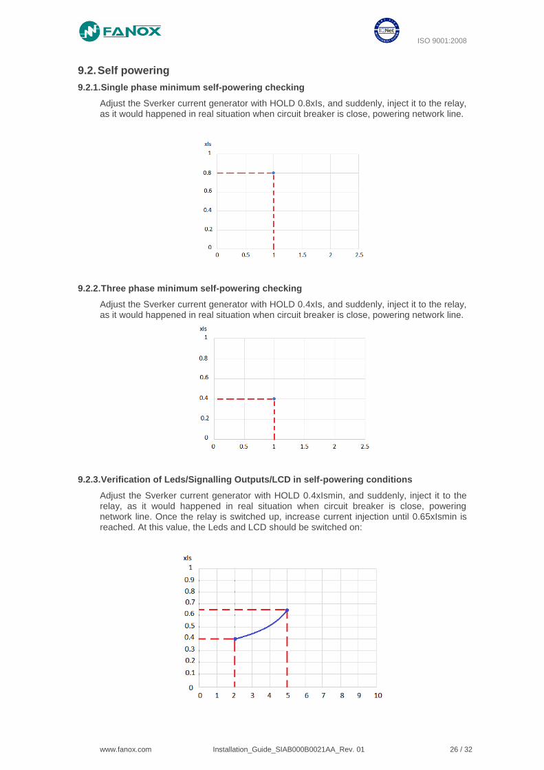
9.2. Self powering
9.2.1. Single phase minimum self-powering checking
Adjust the Sverker current generator with HOLD 0.8xIs, and suddenly, inject it to the relay, as it would happened in real situation when circuit breaker is close, powering network line.
9.2.2. Three phase minimum self-powering checking
Adjust the Sverker current generator with HOLD 0.4xIs, and suddenly, inject it to the relay, as it would happened in real situation when circuit breaker is close, powering network line.
9.2.3. Verification of Leds/Signalling Outputs/LCD in self-powering conditions
Adjust the Sverker current generator with HOLD 0.4xIsmin, and suddenly, inject it to the relay, as it would happened in real situation when circuit breaker is close, powering network line. Once the relay is switched up, increase current injection until 0.65xIsmin is reached. At this value, the Leds and LCD should be switched on:
ISO 9001:2008
www.fanox.com Installation_Guide_SIAB000B0021AA_Rev. 01 27 / 32
9.3. Measurements
The accuracy of the measurement depends on the CT type:
- With CTxxx-5 type < ± 5%.
- With CTxxx-10 type < ± 10%
The relay is able t measure up to 20 times the maximum nominal current of the CT.
9.4. Protection functions
Current injection procedure:
The nominal current adjusted in general settings will be 16 and the CT type will be CT16.
Adjust the Sverker current injector with HOLD 0,8xIsmin, and suddenly, inject it to the relay, as it would happened in real situation when circuit breaker is close, powering network line. From this value, increase the current to achieve the function pick-up and the function trip.
9.4.1. Protection functions testing
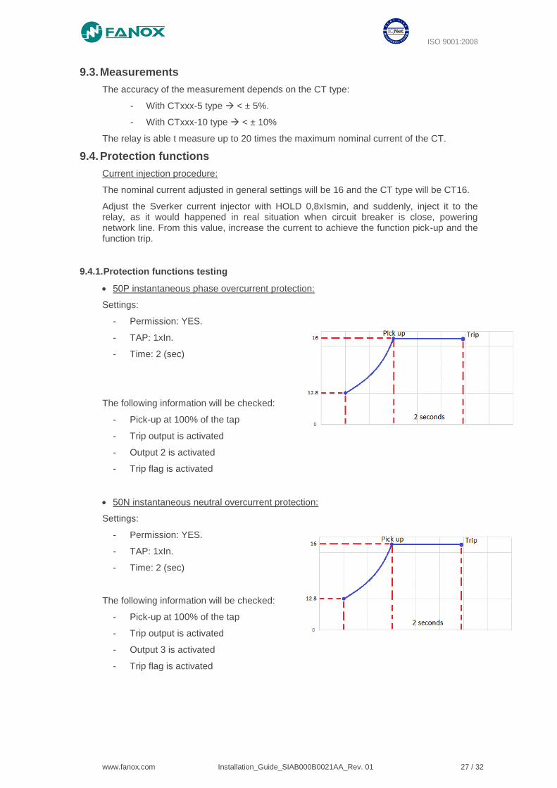
• 50P instantaneous phase overcurrent protection:
Settings:
- Permission: YES.
- TAP: 1xIn.
- Time: 2 (sec)
The following information will be checked:
- Pick-up at 100% of the tap
- Trip output is activated
- Output 2 is activated
- Trip flag is activated
• 50N instantaneous neutral overcurrent protection:
Settings:
- Permission: YES.
- TAP: 1xIn.
- Time: 2 (sec)
The following information will be checked:
- Pick-up at 100% of the tap
- Trip output is activated
- Output 3 is activated
- Trip flag is activated
ISO 9001:2008
www.fanox.com Installation_Guide_SIAB000B0021AA_Rev. 01 28 / 32
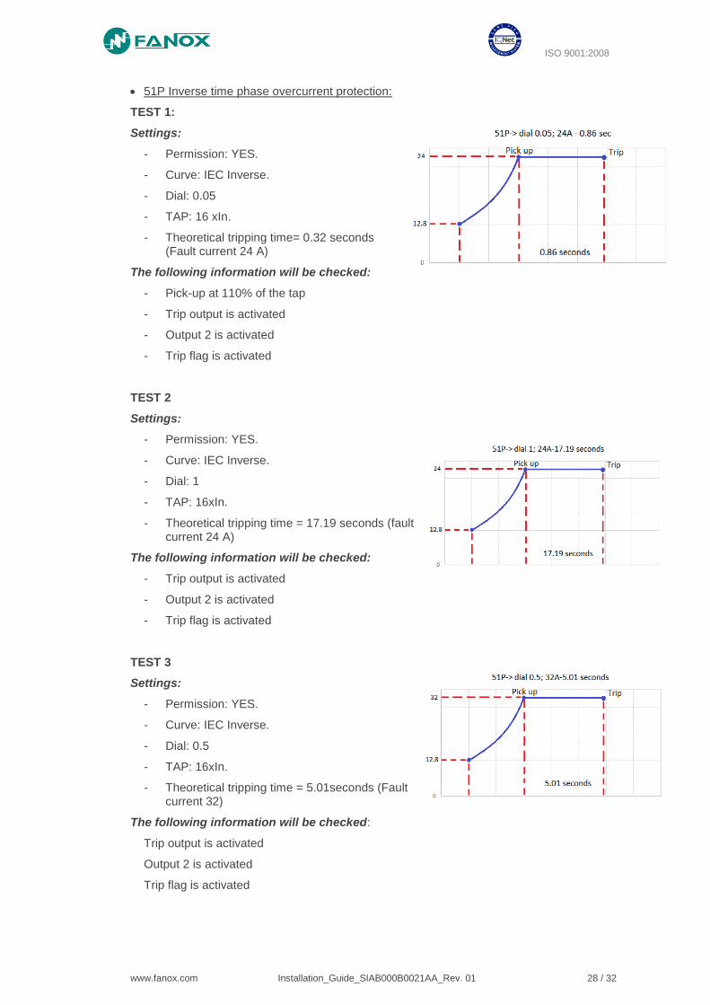
• 51P Inverse time phase overcurrent protection:
TEST 1:
Settings:
- Permission: YES.
- Curve: IEC Inverse.
- Dial: 0.05
- TAP: 16 xIn.
- Theoretical tripping time= 0.32 seconds (Fault current 24 A)
The following information will be checked:
- Pick-up at 110% of the tap
- Trip output is activated
- Output 2 is activated
- Trip flag is activated
TEST 2
Settings:
- Permission: YES.
- Curve: IEC Inverse.
- Dial: 1
- TAP: 16xIn.
- Theoretical tripping time = 17.19 seconds (fault current 24 A)
The following information will be checked:
- Trip output is activated
- Output 2 is activated
- Trip flag is activated
TEST 3
Settings:
- Permission: YES.
- Curve: IEC Inverse.
- Dial: 0.5
- TAP: 16xIn.
- Theoretical tripping time = 5.01seconds (Fault current 32)
The following information will be checked:
Trip output is activated
Output 2 is activated
Trip flag is activated
ISO 9001:2008
www.fanox.com Installation_Guide_SIAB000B0021AA_Rev. 01 29 / 32
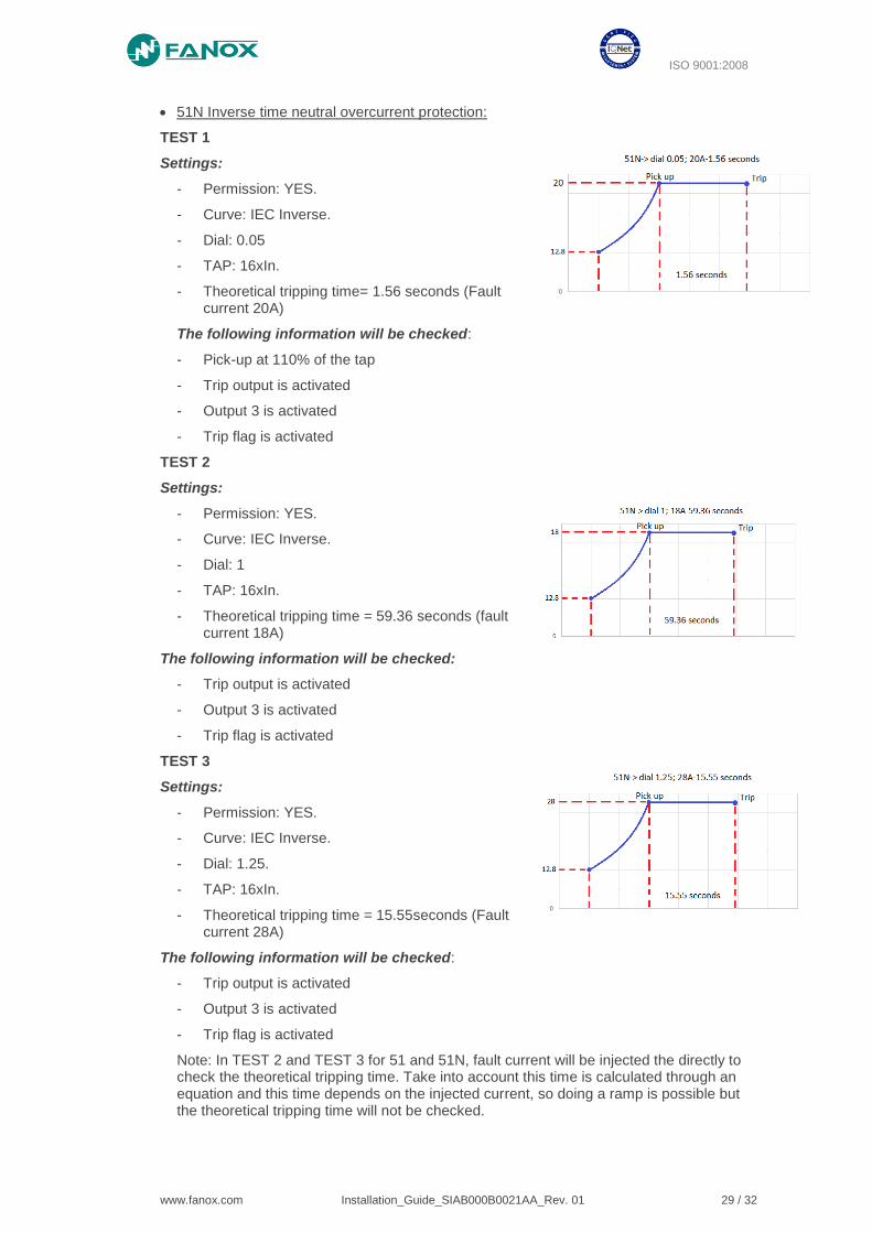
• 51N Inverse time neutral overcurrent protection:
TEST 1
Settings:
- Permission: YES.
- Curve: IEC Inverse.
- Dial: 0.05
- TAP: 16xIn.
- Theoretical tripping time= 1.56 seconds (Fault current 20A)
The following information will be checked:
- Pick-up at 110% of the tap
- Trip output is activated
- Output 3 is activated
- Trip flag is activated
TEST 2
Settings:
- Permission: YES.
- Curve: IEC Inverse.
- Dial: 1
- TAP: 16xIn.
- Theoretical tripping time = 59.36 seconds (fault current 18A)
The following information will be checked:
- Trip output is activated
- Output 3 is activated
- Trip flag is activated
TEST 3
Settings:
- Permission: YES.
- Curve: IEC Inverse.
- Dial: 1.25.
- TAP: 16xIn.
- Theoretical tripping time = 15.55seconds (Fault current 28A)
The following information will be checked:
- Trip output is activated
- Output 3 is activated
- Trip flag is activated
Note: In TEST 2 and TEST 3 for 51 and 51N, fault current will be injected the directly to check the theoretical tripping time. Take into account this time is calculated through an equation and this time depends on the injected current, so doing a ramp is possible but the theoretical tripping time will not be checked.
www.fanox.com Installation_Guide_SIAB000B0021AA_Rev. 01 30 / 32
ISO 9001:2008
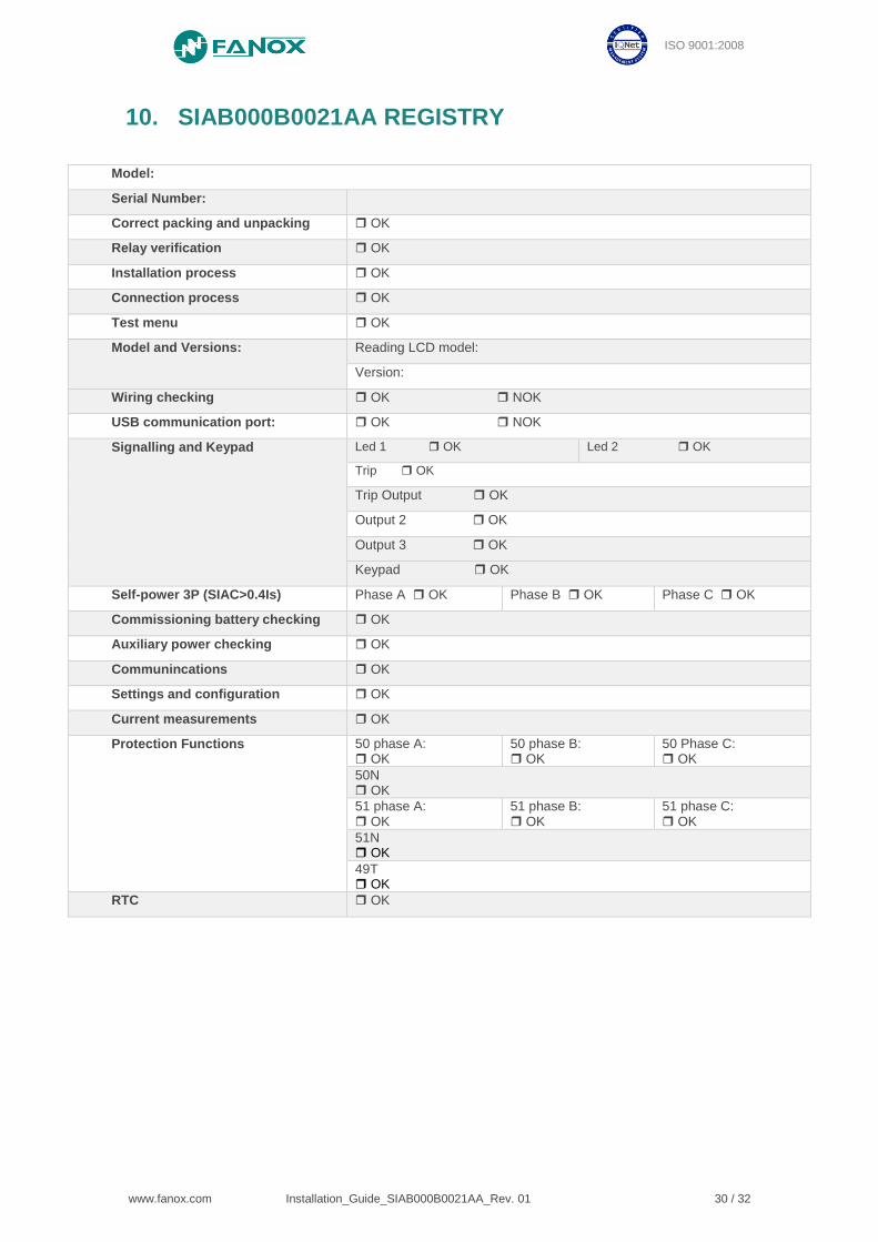
10. SIAB000B0021AA REGISTRY
Model:
Serial Number:
Correct packing and unpacking OK
Relay verification OK
Installation process OK
Connection process OK
Test menu OK
Model and Versions: Reading LCD model:
Version:
Wiring checking OK NOK
USB communication port: OK NOK
Signalling and Keypad Led 1 OK Led 2 OK
Trip OK
Trip Output OK
Output 2 OK
Output 3 OK
Keypad OK
Self-power 3P (SIAC>0.4Is) Phase A OK Phase B OK Phase C OK
Commissioning battery checking OK
Auxiliary power checking OK
Communincations OK
Settings and configuration OK
Current measurements OK
Protection Functions 50 phase A: OK
50 phase B: OK
50 Phase C: OK
50N OK
51 phase A: OK
51 phase B: OK
51 phase C: OK
51N OK
49T OK
RTC OK

www.fanox.com Installation_Guide_SIAB000B0021AA_Rev. 01 31 / 32
ISO 9001:2008
NOTES: …………………………………………………………………………………………. …………………………………………………………………………………………………… …………………………………………………………………………………………………… …………………………………………………………………………………………………… …………………………………………………………………………………………………… …………………………………………………………………………………………………… …………………………………………………………………………………………………… …………………………………………………………………………………………………… …………………………………………………………………………………………………… …………………………………………………………………………………………………… …………………………………………………………………………………………………… …………………………………………………………………………………………………… …………………………………………………………………………………………………… …………………………………………………………………………………………………… …………………………………………………………………………………………………… …………………………………………………………………………………………………… …………………………………………………………………………………………………… …………………………………………………………………………………………………… …………………………………………………………………………………………………… …………………………………………………………………………………………………… …………………………………………………………………………………………………… …………………………………………………………………………………………………… …………………………………………………………………………………………………… …………………………………………………………………………………………………… …………………………………………………………………………………………………… …………………………………………………………………………………………………… …………………………………………………………………………………………………… …………………………………………………………………………………………………… …………………………………………………………………………………………………… …………………………………………………………………………………………………… …………………………………………………………………………………………………… …………………………………………………………………………………………………… …………………………………………………………………………………………………… …………………………………………………………………………………………………… ………………………………………………………………………………………………….... …………………………………………………………………………………………………… …………………………………………………………………………………………………… …………………………………………………………………………………………………… …………………………………………………………………………………………………… …………………………………………………………………………………………………… …………………………………………………………………………………………………… …………………………………………………………………………………………………… …………………………………………………………………………………………………… …………………………………………………………………………………………………… …………………………………………………………………………………………………… …………………………………………………………………………………………………… …………………………………………………………………………………………………… …………………………………………………………………………………………………… …………………………………………………………………………………………………… …………………………………………………………………………………………………… …………………………………………………………………………………………………… …………………………………………………………………………………………………… …………………………………………………………………………………………………… …………………………………………………………………………………………………… …………………………………………………………………………………………………… ……………………………………………………………………………………………………

www.fanox.com Installation_Guide_SIAB000B0021AA_Rev. 01 32 / 32
ISO 9001:2008