Embed Size (px)
Citation preview
PUBLICATION NUMBER PAM--010 November 2, 2007
SELF-PRIMING CENTRIFUGAL PUMPS
APPLICATION MANUAL
PL-2 PL-3 PL-4 PL-6 PL-8 PL-10 PL-12 PH-3 PH-4 PH-6
Application Manual
PAM‐010 Page 2
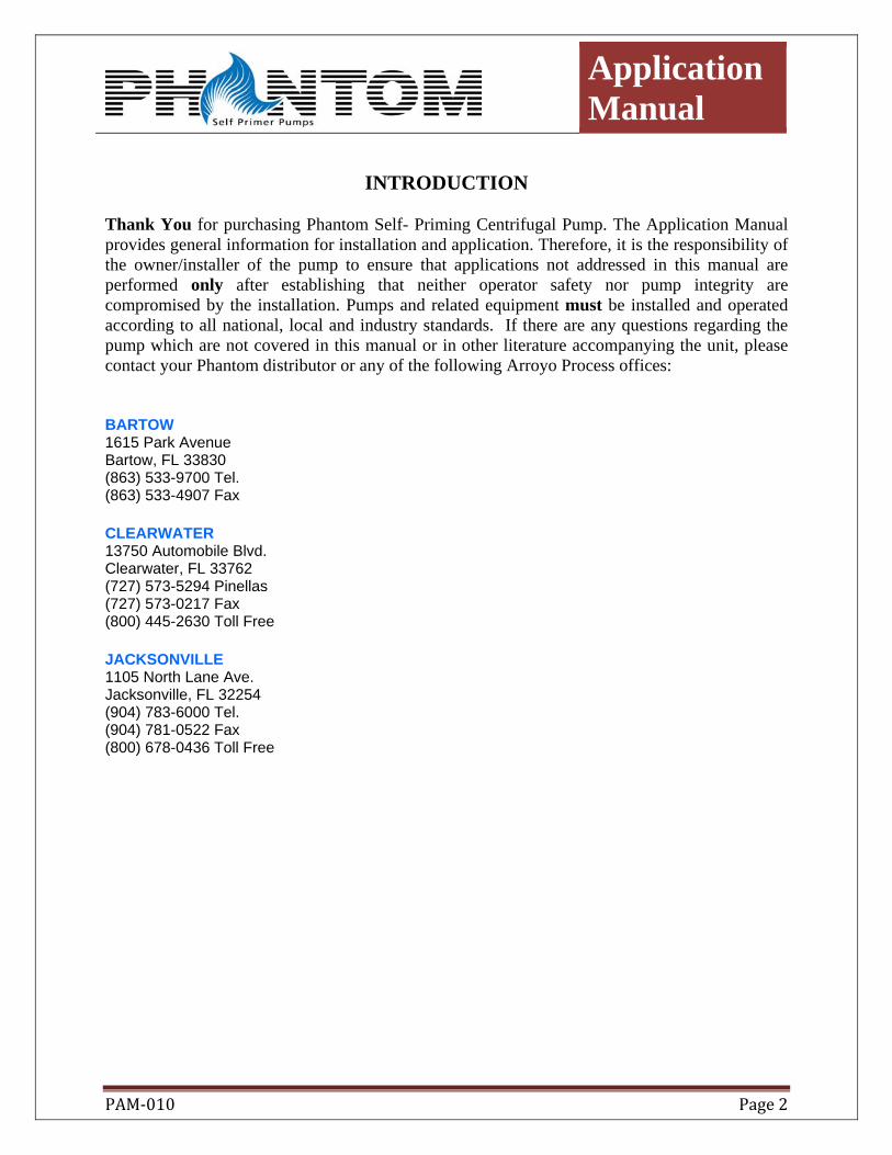
INTRODUCTION
Thank You for purchasing Phantom Self- Priming Centrifugal Pump. The Application Manual provides general information for installation and application. Therefore, it is the responsibility of the owner/installer of the pump to ensure that applications not addressed in this manual are performed only after establishing that neither operator safety nor pump integrity are compromised by the installation. Pumps and related equipment must be installed and operated according to all national, local and industry standards. If there are any questions regarding the pump which are not covered in this manual or in other literature accompanying the unit, please contact your Phantom distributor or any of the following Arroyo Process offices:
BARTOW 1615 Park Avenue Bartow, FL 33830 (863) 533-9700 Tel. (863) 533-4907 Fax
CLEARWATER 13750 Automobile Blvd. Clearwater, FL 33762 (727) 573-5294 Pinellas (727) 573-0217 Fax (800) 445-2630 Toll Free
JACKSONVILLE 1105 North Lane Ave. Jacksonville, FL 32254 (904) 783-6000 Tel. (904) 781-0522 Fax (800) 678-0436 Toll Free
Application Manual
PAM‐010 Page 3
CONTENTS Standard Centrifugal Pumps 4 Self Priming Pumps 5 How to read a pump performance curve Pages 7 Understanding pump applications 10 How to select the correct pump for the job 12 Pressure required at end of discharge line 12 Applications at Higher Elevations 13 Friction Loss in Pipe Fittings 15 Convert Chart 16 Capacity and flow chart 17 Theoretical Discharge of Nozzles 18 Where to use self priming pumps 19
Application Manual
PAM‐010 Page 4
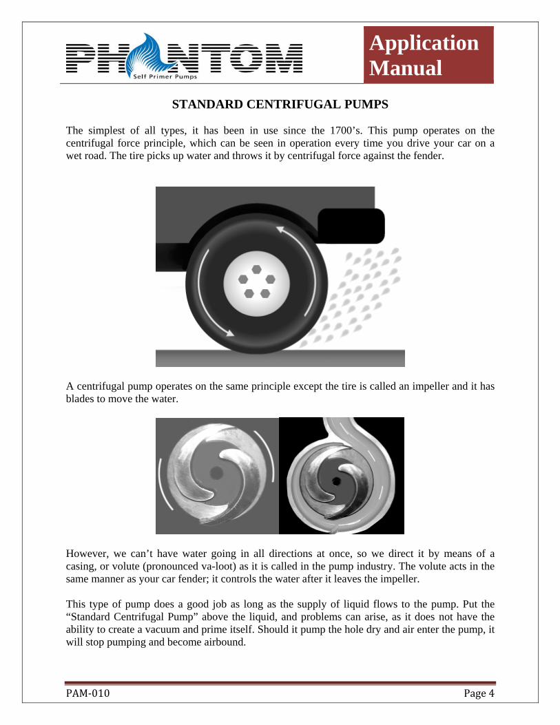
STANDARD CENTRIFUGAL PUMPS The simplest of all types, it has been in use since the 1700’s. This pump operates on the centrifugal force principle, which can be seen in operation every time you drive your car on a wet road. The tire picks up water and throws it by centrifugal force against the fender.
A centrifugal pump operates on the same principle except the tire is called an impeller and it has blades to move the water.
However, we can’t have water going in all directions at once, so we direct it by means of a casing, or volute (pronounced va-loot) as it is called in the pump industry. The volute acts in the same manner as your car fender; it controls the water after it leaves the impeller.
This type of pump does a good job as long as the supply of liquid flows to the pump. Put the “Standard Centrifugal Pump” above the liquid, and problems can arise, as it does not have the ability to create a vacuum and prime itself. Should it pump the hole dry and air enter the pump, it will stop pumping and become airbound.
Application Manual
PAM‐010 Page 5
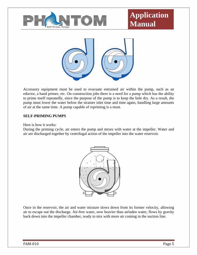
Accessory equipment must be used to evacuate entrained air within the pump, such as an eductor, a hand primer, etc. On construction jobs there is a need for a pump which has the ability to prime itself repeatedly, since the purpose of the pump is to keep the hole dry. As a result, the pump must lower the water below the strainer inlet time and time again, handling large amounts of air at the same time. A pump capable of repriming is a must. SELF-PRIMING PUMPS Here is how it works: During the priming cycle, air enters the pump and mixes with water at the impeller. Water and air are discharged together by centrifugal action of the impeller into the water reservoir.
Once in the reservoir, the air and water mixture slows down from its former velocity, allowing air to escape out the discharge. Air-free water, now heavier than airladen water, flows by gravity back down into the impeller chamber, ready to mix with more air coming in the suction line.
Application Manual
PAM‐010 Page 6
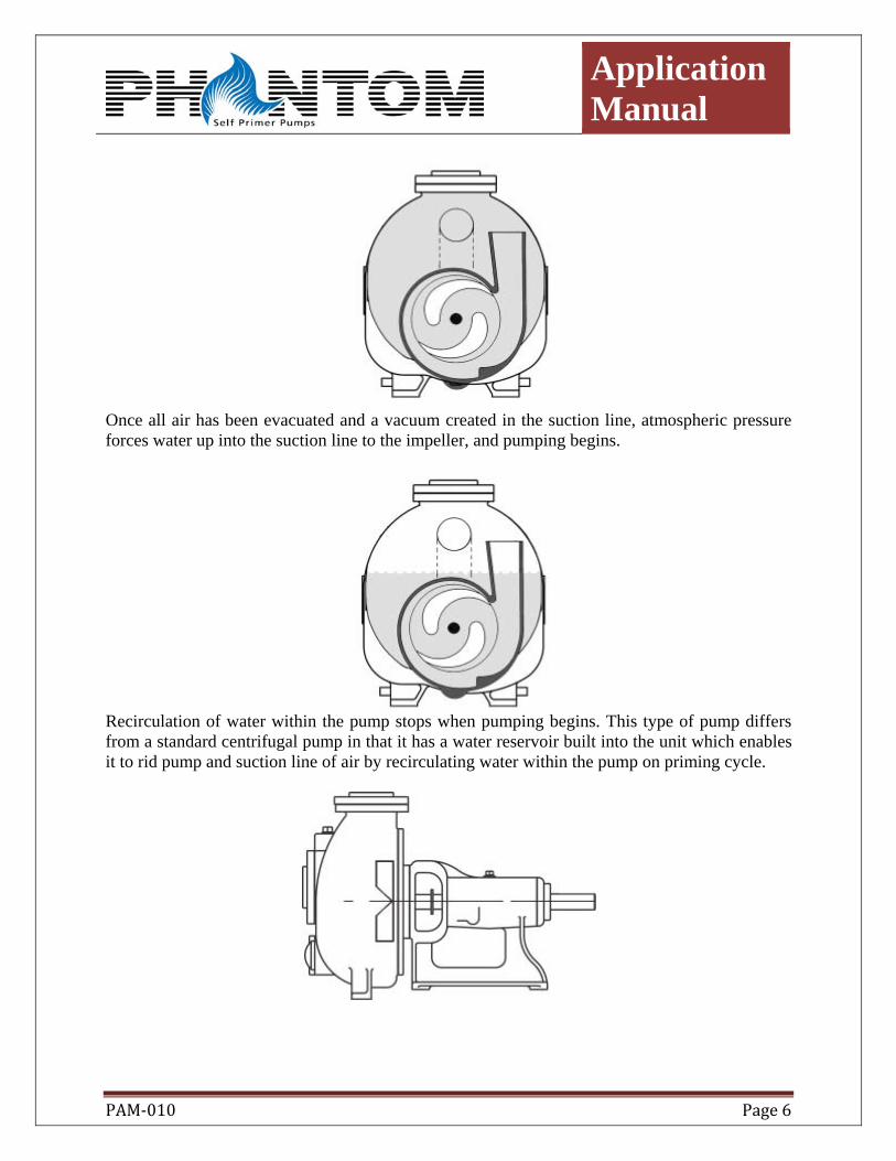
Once all air has been evacuated and a vacuum created in the suction line, atmospheric pressure forces water up into the suction line to the impeller, and pumping begins.
Recirculation of water within the pump stops when pumping begins. This type of pump differs from a standard centrifugal pump in that it has a water reservoir built into the unit which enables it to rid pump and suction line of air by recirculating water within the pump on priming cycle.
Application Manual
PAM‐010 Page 7
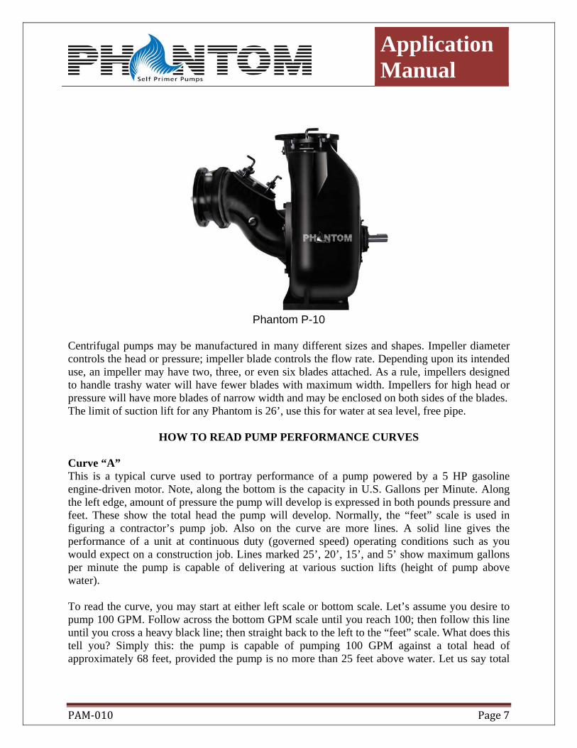
Phantom P-10
Centrifugal pumps may be manufactured in many different sizes and shapes. Impeller diameter controls the head or pressure; impeller blade controls the flow rate. Depending upon its intended use, an impeller may have two, three, or even six blades attached. As a rule, impellers designed to handle trashy water will have fewer blades with maximum width. Impellers for high head or pressure will have more blades of narrow width and may be enclosed on both sides of the blades. The limit of suction lift for any Phantom is 26’, use this for water at sea level, free pipe.
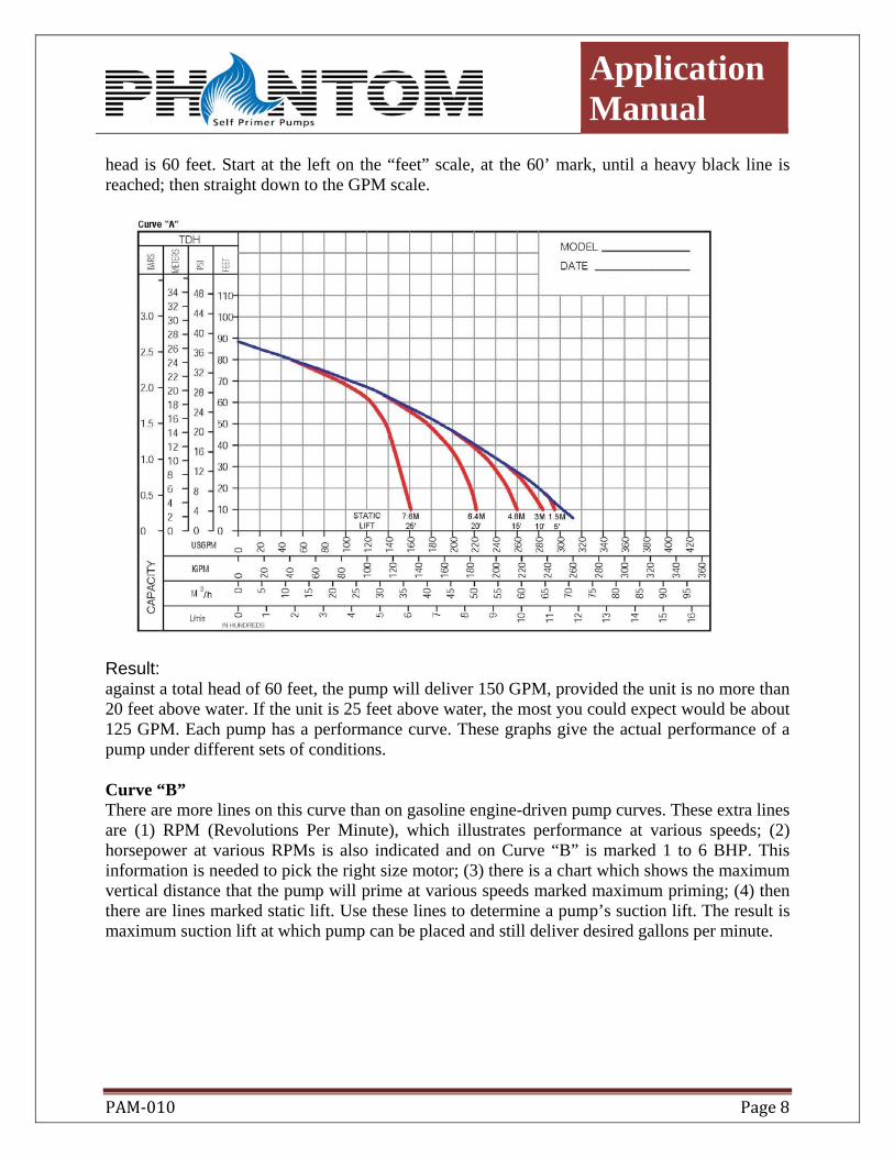
HOW TO READ PUMP PERFORMANCE CURVES Curve “A” This is a typical curve used to portray performance of a pump powered by a 5 HP gasoline engine-driven motor. Note, along the bottom is the capacity in U.S. Gallons per Minute. Along the left edge, amount of pressure the pump will develop is expressed in both pounds pressure and feet. These show the total head the pump will develop. Normally, the “feet” scale is used in figuring a contractor’s pump job. Also on the curve are more lines. A solid line gives the performance of a unit at continuous duty (governed speed) operating conditions such as you would expect on a construction job. Lines marked 25’, 20’, 15’, and 5’ show maximum gallons per minute the pump is capable of delivering at various suction lifts (height of pump above water). To read the curve, you may start at either left scale or bottom scale. Let’s assume you desire to pump 100 GPM. Follow across the bottom GPM scale until you reach 100; then follow this line until you cross a heavy black line; then straight back to the left to the “feet” scale. What does this tell you? Simply this: the pump is capable of pumping 100 GPM against a total head of approximately 68 feet, provided the pump is no more than 25 feet above water. Let us say total
Application Manual
PAM‐010 Page 8
head is 60 feet. Start at the left on the “feet” scale, at the 60’ mark, until a heavy black line is reached; then straight down to the GPM scale.
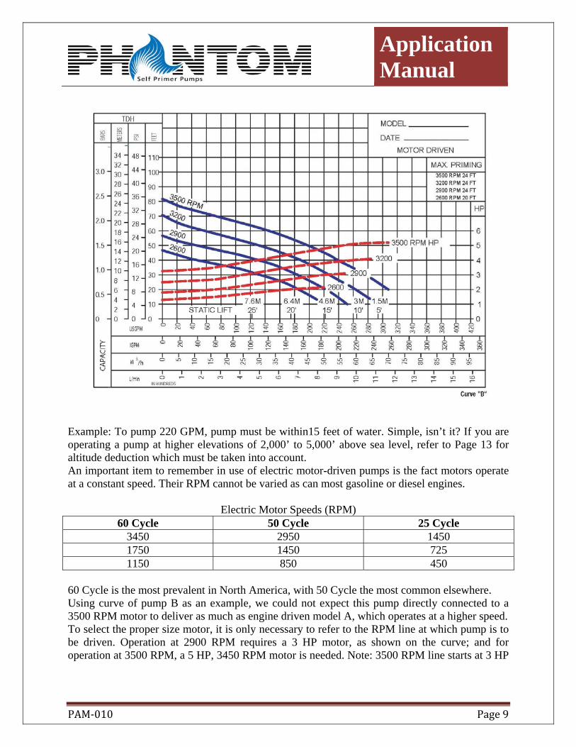
Result: against a total head of 60 feet, the pump will deliver 150 GPM, provided the unit is no more than 20 feet above water. If the unit is 25 feet above water, the most you could expect would be about 125 GPM. Each pump has a performance curve. These graphs give the actual performance of a pump under different sets of conditions. Curve “B” There are more lines on this curve than on gasoline engine-driven pump curves. These extra lines are (1) RPM (Revolutions Per Minute), which illustrates performance at various speeds; (2) horsepower at various RPMs is also indicated and on Curve “B” is marked 1 to 6 BHP. This information is needed to pick the right size motor; (3) there is a chart which shows the maximum vertical distance that the pump will prime at various speeds marked maximum priming; (4) then there are lines marked static lift. Use these lines to determine a pump’s suction lift. The result is maximum suction lift at which pump can be placed and still deliver desired gallons per minute.
Application Manual
PAM‐010 Page 9
Example: To pump 220 GPM, pump must be within15 feet of water. Simple, isn’t it? If you are operating a pump at higher elevations of 2,000’ to 5,000’ above sea level, refer to Page 13 for altitude deduction which must be taken into account. An important item to remember in use of electric motor-driven pumps is the fact motors operate at a constant speed. Their RPM cannot be varied as can most gasoline or diesel engines.
Electric Motor Speeds (RPM) 60 Cycle 50 Cycle 25 Cycle
3450 2950 1450 1750 1450 725 1150 850 450
60 Cycle is the most prevalent in North America, with 50 Cycle the most common elsewhere. Using curve of pump B as an example, we could not expect this pump directly connected to a 3500 RPM motor to deliver as much as engine driven model A, which operates at a higher speed. To select the proper size motor, it is only necessary to refer to the RPM line at which pump is to be driven. Operation at 2900 RPM requires a 3 HP motor, as shown on the curve; and for operation at 3500 RPM, a 5 HP, 3450 RPM motor is needed. Note: 3500 RPM line starts at 3 HP
Application Manual
PAM‐010 Page 10
and goes up to 5 HP. This means you would overload a 3 HP motor, as it is necessary to use 5 HP. Many times your customer will desire to use an electric motor driven pump. Curves depicting performance of these pumps are slightly different. Curve “B” illustrates these differences, for the same pump model as Curve “A”
UNDERSTANDING PUMP APPLICATIONS
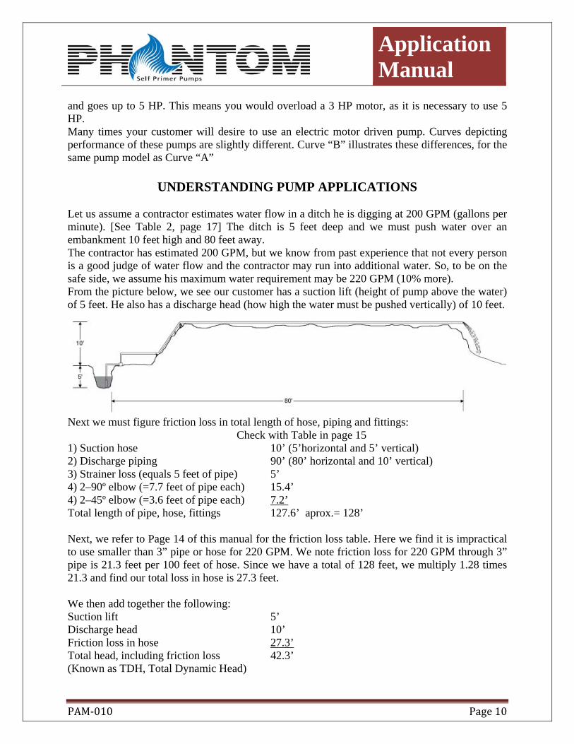
Let us assume a contractor estimates water flow in a ditch he is digging at 200 GPM (gallons per minute). [See Table 2, page 17] The ditch is 5 feet deep and we must push water over an embankment 10 feet high and 80 feet away. The contractor has estimated 200 GPM, but we know from past experience that not every person is a good judge of water flow and the contractor may run into additional water. So, to be on the safe side, we assume his maximum water requirement may be 220 GPM (10% more). From the picture below, we see our customer has a suction lift (height of pump above the water) of 5 feet. He also has a discharge head (how high the water must be pushed vertically) of 10 feet.
Next we must figure friction loss in total length of hose, piping and fittings:
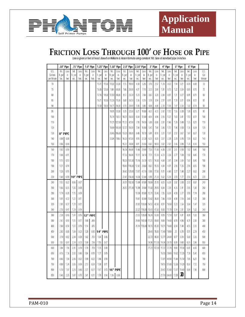
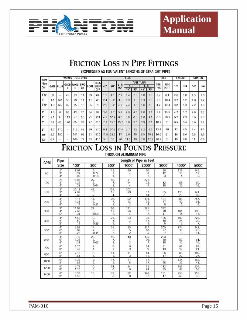
Check with Table in page 15 1) Suction hose 10’ (5’horizontal and 5’ vertical) 2) Discharge piping 90’ (80’ horizontal and 10’ vertical) 3) Strainer loss (equals 5 feet of pipe) 5’ 4) 2–90º elbow (=7.7 feet of pipe each) 15.4’ 4) 2–45º elbow (=3.6 feet of pipe each) 7.2’ Total length of pipe, hose, fittings 127.6’ aprox.= 128’ Next, we refer to Page 14 of this manual for the friction loss table. Here we find it is impractical to use smaller than 3” pipe or hose for 220 GPM. We note friction loss for 220 GPM through 3” pipe is 21.3 feet per 100 feet of hose. Since we have a total of 128 feet, we multiply 1.28 times 21.3 and find our total loss in hose is 27.3 feet. We then add together the following: Suction lift 5’ Discharge head 10’ Friction loss in hose 27.3’ Total head, including friction loss 42.3’ (Known as TDH, Total Dynamic Head)
Application Manual
PAM‐010 Page 11
Application Manual
PAM‐010 Page 12
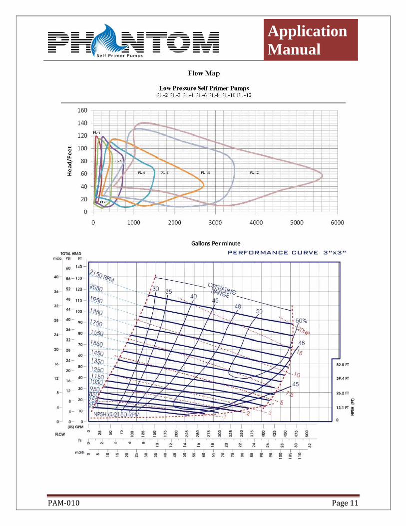
We must now find a pump which will give us 220 gallons per minute at a total head of 42.3 feet with the pump 10 feet above water. Here we note our head condition of 42.3 feet is close to curve of the pump, at which point the pump will deliver 200 GPM when 10 feet above water. Therefore, we select a 3 inch pump that will need a 5HP motor, and the speed should be 1350 RPM. and an Efficiency of 45%
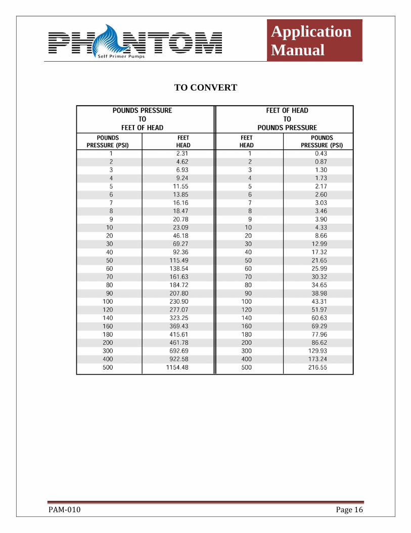
HOW TO SELECT THE RIGHT PUMP FOR THE JOB Nine times out of ten, your customer will tell you he wants a 2-, 3- or 4-inch pump. Sometimes, however, your customer will ask you to figure the correct pump for a certain application. There are several things we must know before we attempt to select the proper pump: 1) How many gallons per minute are we going to pump? 2) How high is the pump above water? 3) How high must the water be pushed after it leaves the pump? 4) The total length of hose or pipe to be used. 5) Is water merely to be “dumped” at the end of the discharge run, or will it be used to perform work? (See Special Conditions in Figuring Pump Applications) PRESSURE REQUIRED AT END OF DISCHARGE LINE Some applications, such as gravel washing, jetting, piling, and borrow pit sprinkling, require not only delivering water at a point some distance from the pump, but also supplying a certain amount of pressure at the end of the line. As an example, if 40 pounds of pressure were required for gravel washing in our illustration, this figure must be added to the result of our first four steps. It is easier to convert pounds pressure to feet of head, as we have used feet in figuring the application. From the table on Page 16 you will note 40 pounds is equal to approximately 92.3 feet of head. Here is the result: Total Head, including friction loss 42.3’ Pressure required at end of pipe 92.3’ New Total Head (TDH) 134.6’ We now need to make a new pump selection. TO CONVERT INTO MULTIPLY BY
Pounds per sq. in. Feet of Water 2.31 Feet (of water) Pounds per sq. in. 0.433 Inches of Mercury Feet of Water 1.133
Application Manual
PAM‐010 Page 13
APPLICATIONS AT HIGHER ELEVATIONS Pump performance is calculated and plotted on all published data at sea level. At elevations of 1,000 feet and below, this data may generally safely be used, but at higher elevations both pump and engine lose output. Following is listed the loss in performance which may be expected compared with sea level performance: ELEVATION GPM HEAD 2,000 Feet -3% -5% 4,000 Feet -5% -9% 6,000 Feet -7% -13% 8,000 Feet -9% -17% 10,000 Feet -12% -22% Suction lift also suffers and adjustments must be made. The table below illustrates the equivalent suction lifts for various altitudes. Example: At 6,000 feet elevation, a pump must be placed with 6.9 feet of the water to deliver as much water in GPM (gallons per minute) as the same unit would at a 10-foot suction lift at sea level. Elevation Suction Lifts (in Feet) Sea Level 10.0 15.0 20.0 25.0 2,000 Feet 8.8 13.2 17.6 22.0 4,000 Feet 7.8 11.7 15.6 19.5 6,000 Feet 6.9 10.4 13.8 17.3 8,000 Feet 6.2 9.3 12.4 15.5 10,000 Feet 5.7 8.6 11.4 14.3 NOTE: All references to GPM in this booklet refer to US gallons per minute. (1) To convert imperial gallons to US gallons, multiply imperial gallons by 1.2. (2) To convert US gallons to imperial gallons, multiply US gallons by .83. ENGINES, TOO, SUFFER FROM ALTITUDE Most engines are rated by the manufacturer using 60 degrees Fahrenheit at sea level. Deductions must be made from the rated horsepower as follows: For each 1,000 feet above sea level, deduct 3.5%, and 1% for each 10 degrees Fahrenheit above 60 degrees.
Application Manual
PAM‐010 Page 14
Application Manual
PAM‐010 Page 15
Application Manual
PAM‐010 Page 16
TO CONVERT
Application Manual
PAM‐010 Page 17
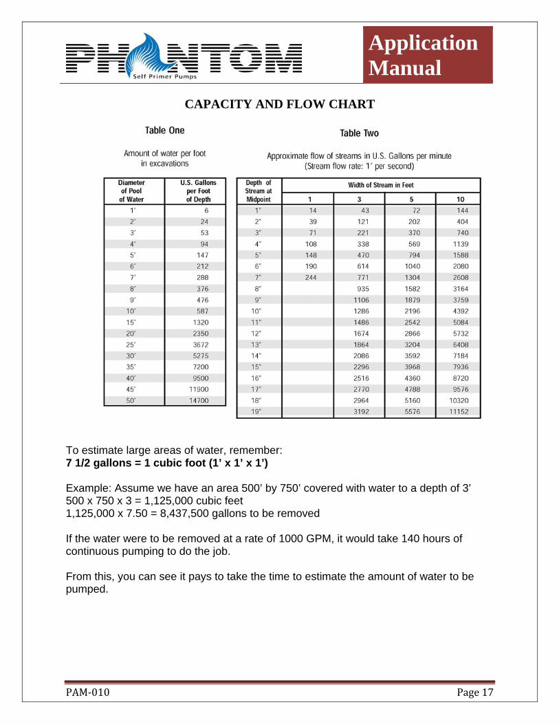
CAPACITY AND FLOW CHART
To estimate large areas of water, remember: 7 1/2 gallons = 1 cubic foot (1’ x 1’ x 1’) Example: Assume we have an area 500’ by 750’ covered with water to a depth of 3’ 500 x 750 x 3 = 1,125,000 cubic feet 1,125,000 x 7.50 = 8,437,500 gallons to be removed If the water were to be removed at a rate of 1000 GPM, it would take 140 hours of continuous pumping to do the job. From this, you can see it pays to take the time to estimate the amount of water to be pumped.

Application Manual
PAM‐010 Page 18
THEORETICAL DISCHARGE OF NOZZLES IN U.S. GALLONS PER MINUTE

Application Manual
PAM‐010 Page 19
WHERE TO USE SELF PRIMING PUMPS CONSTRUCTION USES Pump Out – 1. Small excavations 2. Foundations 3. Manholes 4. Several well points 5. Strip mines 6. Flood water 7. Sewage by-passing Fill – 1. Water wagons General Uses – 1. Wash down equipment 2. Barge cleaning 3. Marinas FARM USES Irrigation Uses – 1. Truck farms 2. Fill stock tanks 3. Wash down barn areas 4. Transfer liquid manures 5. Washing of equipment 6. Pump out flood water 7. Standby fire protection 8. Water transfer at fish farms