Embed Size (px)
Citation preview
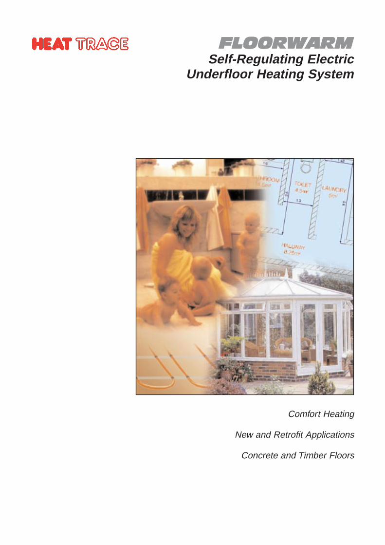
FFLLOOOORRWWAARRMMSelf-Regulating Electric
Underfloor Heating System
Comfort Heating
New and Retrofit Applications
Concrete and Timber Floors

The Applications
Floor warming is generally provided assupplementary heating to an existing heatsource in order to keep floor surfaces at acomfortable temperature.
FLOORWARM is suitable for domestic,commercial and industrial buildings. It maybe incorporated into new buildings andextensions, or retro-fitted to existing floors.FLOORWARM can be safely used withwooden and concrete floors
How it Works
FLOORWARM self-regulating heating cable isinstalled beneath the floor, often embeddedin the concrete, or in a screed, although itcan also be safely used with woodenfloors.
The principle of FLOORWARM, when usedwith a concrete floor, is to utilise the highthermal capacity of the floor slab as a heatreservoir which stores and emits heat on acontinuous basis.
When initially energised the heater works toits maximum output, reducing as the slabtemperature rises, until the requiredoptimum heat output is achieved.
By installing a self-regulating heating cable,that varies its output relative to the floortemperature, it is possible to achieve aneven heat distribution without localisedoverheating.
Electric Self-Regulating Underfloor Heating System
Floor Warming Principles
A comfortable room temperature largelydepends on the mean effectivetemperature, which is a function of theambient air temperature and the averageradiant surface temperature. Where largewarm surfaces such as the floor exist, it ispossible to achieve comfortable conditionswith a cooler air temperature. This resultsin a "fresher" environment and will meanreduced heat losses from the building withsubsequent savings in energy costs.
It is more comfortable and far safer to havean evenly distributed lower temperature ofbetween 20 - 30°C, than it is to have asingle high temperature heat source ofaround 100°C, or more, in one area of theroom, distributing heat by radiation andconvection. It is also more efficient andsafer to generate heat at the required floortemperature, rather than to generateexcessive temperatures and allowdistribution to reduce the temperature tothe required comfort level.
Ideal living room temperature gradients areconsidered to be about 24°C at floor leveland around 18-20°C at head level.FLOORWARM allows the latent heat stored inthe floor to be released in such a way as toachieve these conditions more effectively.The self-regulating characteristic ofFLOORWARM ensures that, as the roomreaches the desired temperature, thecapability of the floor to emit heatdiminishes. Furthermore, lying on the floorwill not result in over heating - making itperfectly safe for children and pets.
Efficiency
For greater efficiency, heat input to the floormay be provided via off peak, low tariffelectricity if, and when, it is available.Additional thermostat and timer controlsmay also be utilised for additional energysavings. An insulated floor isrecommended where possible.
Flexibility
FLOORWARM’S self-regulating capability alsoensures that the system responds tolocalised additional heat losses that mayoccur at open windows, doors, etc., byautomatically increasing the heat outputfrom the floor in that area. This self-regulating capability also ensures that thefloor cannot overheat, thus protectingagainst discomfort and inefficient use ofenergy.
The installed heating load determines theability of the system to achieve the requiredfloor operating temperature.
Bathroom Floors
Conservatory Floor
Room heating using traditional methods
Room heating using FLOORWARM system
The heat output from FLOORWARM issufficiently low to enable the heater to beused with a waterproof membrane in floorssubject to moisture, for example inbathrooms, shower rooms, etc.
Other Uses
In addition to domestic applications suchas conservatories, bathrooms, living rooms,bedrooms, loft areas, etc., FLOORWARM
offers equal benefits for commercialpremises such as offices, atria, receptionareas, rest rooms, etc.
Traditional Heating vs. FLOORWARM
With traditional central heating, the airimmediately around the radiator is heatedand, as the warm air rises, the heat isconcentrated high in the room whilst thefloor area remains colder.
FLOORWARM, however, radiates heatupwards from the floor - resulting in amuch more comfortable and even heatdistribution throughout the whole room.
2
“Self-regulating heaters cannot overheat or burn out”
Applications
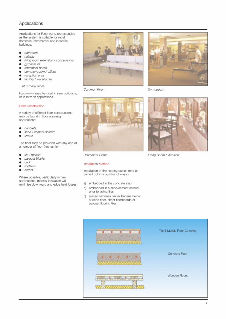
Applications for FLOORWARM are extensiveas the system is suitable for mostdomestic, commercial and industrialbuildings.
●● bathroom●● hallway●● living room extension / conservatory●● gymnasium●● retirement home●● common room / offices ●● reception area●● factory / warehouse
...... plus many more
FLOORWARM may be used in new buildings,or in retro-fit applications.
Floor Construction
A variety of different floor constructionsmay be found in floor warmingapplications:-
●● concrete●● sand / cement screed●● timber
The floor may be provided with any one ofa number of floor finishes, ie:-
●● tile / marble●● parquet blocks●● cork●● linoleum●● carpet
Where possible, particularly in newapplications, thermal insulation willminimise downward and edge heat losses.
Common Room Gymnasium
Retirement Home Living Room Extension
Tile & Marble Floor Covering
Concrete Floor
Wooden Floors
3
Installation Method
Installation of the heating cables may becarried out in a number of ways:-
a) embedded in the concrete slab
b) embedded in a sand/cement screedprior to laying tiles
c) placed between timber battens belowa wood floor, either floorboards orparquet flooring tiles
Applications
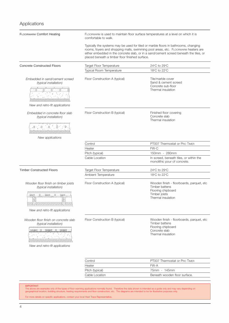
FLOORWARM Comfort Heating
Target Floor Temperature 24oC to 29oC
Typical Room Temperature 18oC to 22oC
Floor Construction A (typical) Tile/marble coverSand & cement screedConcrete sub-floorThermal insulation
Floor Construction B (typical) Finished floor coveringConcrete slabThermal insulation
Control PT007 Thermostat or PRO TIMER
Heater FW-C
Pitch (typical) 150mm - 280mm
Cable Location In screed, beneath tiles, or within themonolithic pour of concrete.
Embedded in sand/cement screed(typical installation)
Embedded in concrete floor slab(typical installation)
Wooden floor finish on timber joists(typical installation)
Target Floor Temperature 24oC to 29oC
Ambient Temperature 18oC to 22oC
Floor Construction A (typical) Wooden finish - floorboards, parquet, etcTimber battensFlooring chipboardTimber joistsThermal insulation
Floor Construction B (typical) Wooden finish - floorboards, parquet, etcTimber battensFlooring chipboardConcrete slabThermal insulation
Control PT007 Thermostat or PRO TIMER
Heater FW-A
Pitch (typical) 75mm - 145mm
Cable Location Beneath wooden floor surface.
Wooden floor finish on concrete slab(typical installation)
New and retro-fit applications
New and retro-fit applications
New applications
4
IMPORTANTThe above are examples only of the types of floor warming applications normally found. Therefore the data shown is intended as a guide only and may vary depending ongeographical location, building structure, heating requirements and floor construction, etc. The diagrams are intended to be for illustrative purposes only.
For more details on specific applications, contact your local Heat Trace Representative.
FLOORWARM is used to maintain floor surface temperatures at a level on which it iscomfortable to walk.
Typically the systems may be used for tiled or marble floors in bathrooms, changingrooms, foyers and shopping malls, swimming pool areas, etc. FLOORWARM heaters areeither embedded in the concrete slab, or in a sand/cement screed beneath the tiles, orplaced beneath a timber floor finished surface.
New and retro-fit applications
Concrete Constructed Floors
Timber Constructed Floors
Design Guide
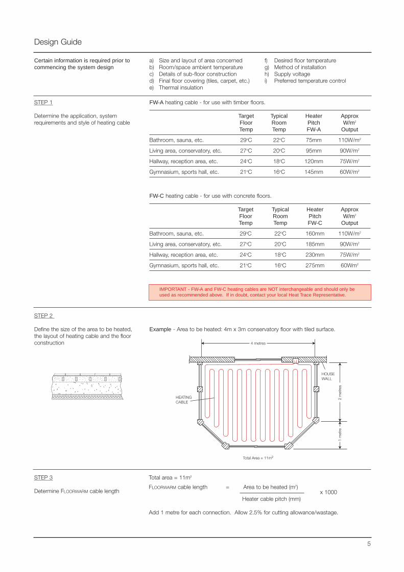
STEP 1
Determine the application, systemrequirements and style of heating cable
FW-A heating cable - for use with timber floors.
Target Typical Heater ApproxFloor Room Pitch W/m2
Temp Temp FW-A Output
Bathroom, sauna, etc. 29oC 22oC 75mm 110W/m2
Living area, conservatory, etc. 27oC 20oC 95mm 90W/m2
Hallway, reception area, etc. 24oC 18oC 120mm 75W/m2
Gymnasium, sports hall, etc. 21oC 16oC 145mm 60W/m2
Certain information is required prior tocommencing the system design
a) Size and layout of area concernedb) Room/space ambient temperaturec) Details of sub-floor constructiond) Final floor covering (tiles, carpet, etc.)e) Thermal insulation
f) Desired floor temperatureg) Method of installationh) Supply voltagei) Preferred temperature control
STEP 2
Define the size of the area to be heated,the layout of heating cable and the floorconstruction
Example - Area to be heated: 4m x 3m conservatory floor with tiled surface.
5
STEP 3
Determine FLOORWARM cable length
Total area = 11m2
FLOORWARM cable length = Area to be heated (m2)x 1000
Heater cable pitch (mm)
Add 1 metre for each connection. Allow 2.5% for cutting allowance/wastage.
IMPORTANT - FW-A and FW-C heating cables are NOT interchangeable and should only beused as recommended above. If in doubt, contact your local Heat Trace Representative.
FW-C heating cable - for use with concrete floors.
Target Typical Heater ApproxFloor Room Pitch W/m2
Temp Temp FW-C Output
Bathroom, sauna, etc. 29oC 22oC 160mm 110W/m2
Living area, conservatory, etc. 27oC 20oC 185mm 90W/m2
Hallway, reception area, etc. 24oC 18oC 230mm 75W/m2
Gymnasium, sports hall, etc. 21oC 16oC 275mm 60Wm2
STEP 6
Connection to suitable electrical supply
The heating circuits may be connected to an existing electrical supply only if provided witha correctly rated over-current and earth leakage protection device (MCB/RCD).
The heating cable is terminated using the TK/FW supplied complete with a 2 metre coldlead. The cold lead is terminated into a suitable junction box mounted on the wall.
This junction box is fed from the Local Distribution Panel (LDP). Where total loads exceedthe rated switch capacity of the chosen controller a suitably rated contactor box shall beused.
STEP 7
Determine power feed cable requirements
Connecting cables from the controller to each circuit power connection, and from thecontrollers to the power supply, must be correctly sized to satisfy Electrical WiringRegulations and local/national standards or codes. Sizing is determined by the maximumallowable volt drop and the current carried by the supply cable.
Generally, supply cables may be sized according to the following table:
MCB Type C or D Heater Supply Cables Max. Supply Cable LengthRating Type Size (min) 115V 230V20A FW-A 2.5mm2 35m 71m20A FW-C 2.5mm2 33m 68m
Important: a residual current device (rcd), 30mA is required.
Design Guide
STEP 5
Determine the method of control
Simple ON/OFF control may be achieved by using a FLOORWARM PT007 Thermostat, whichcan be adjusted to suit the desired floor temperature.
Alternatively, energy efficiency may be improved by utilising the FLOORWARM PRO TIMER
programmable timer control. This enables automatic day/week timer settings to beprogrammed into the system, de-energising the system during periods when the building,or room is unoccupied.
Additional operating cost savings may achieved when the FLOORWARM PRO TIMER isprogrammed to take advantage of off-peak tariffs when they are available.
Electronic controllers are recommended because of their accurate regulation and narrowswitch differential.
6
STEP 4
Determine the number of heating circuitsand the electrical protection requirements
Circuit protection is provided by Type C or D circuit breakers to EN60898:1991 or equal,sized as per the following table (based on 20°C start-up).
Circuit Breaker Supply Maximum Circuit Length (for 20°C start-up)Size Voltage FW-C FW-A
20A 115VAC 52m (58m) 92m (113m)20A 230VAC 102m (116m) 184m (226m)(Figures in parenthesis are maximum circuit lengths when both ends are connected to theelectrical supply ie. reduced volt drop).
A residual circuit breaker (rcd), 30mA sensitivity must be provided. This is provided asstandard with the Heat Trace’s Local Distribution Panel (LDP) which is available with 3, 6 or9 circuit capacities, each fitted with 20 amp MCB/RCDs as standard.
More than one heating circuit may be connected to a single circuit breaker provided thatthe maximum heater length does not exceed the breaker capacity.
If a number of rooms are being heated, it is recommended that each room should haveindividual circuits and be controlled separately.
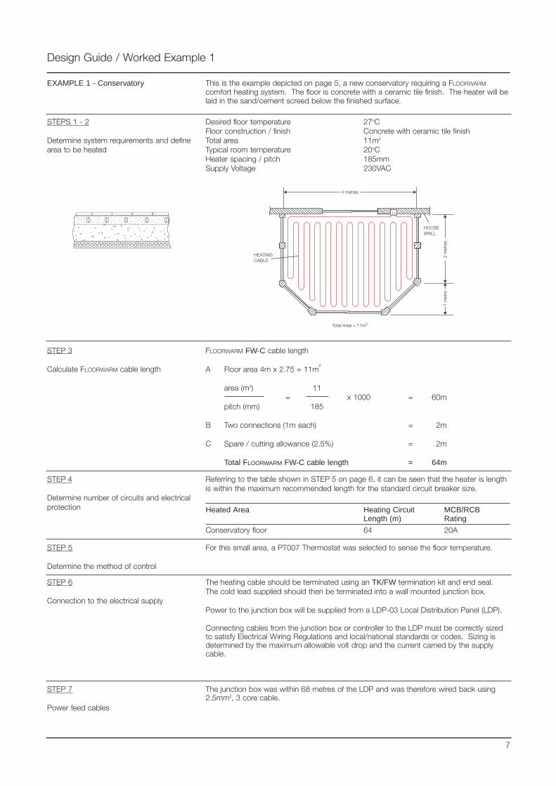
Design Guide / Worked Example 1
This is the example depicted on page 5, a new conservatory requiring a FLOORWARM
comfort heating system. The floor is concrete with a ceramic tile finish. The heater will belaid in the sand/cement screed below the finished surface.
EXAMPLE 1 - Conservatory
Desired floor temperature 27oCFloor construction / finish Concrete with ceramic tile finishTotal area 11m2
Typical room temperature 20oCHeater spacing / pitch 185mmSupply Voltage 230VAC
STEP 3
Calculate FLOORWARM cable length
FLOORWARM FW-C cable length
A Floor area 4m x 2.75 = 11m2
area (m2) 11= x 1000 = 60m
pitch (mm) 185
B Two connections (1m each) = 2m
C Spare / cutting allowance (2.5%) = 2m
Total FLOORWARM FW-C cable length = 64m
STEP 4
Determine number of circuits and electricalprotection
Referring to the table shown in STEP 5 on page 6, it can be seen that the heater is lengthis within the maximum recommended length for the standard circuit breaker size.
Heated Area Heating Circuit MCB/RCBLength (m) Rating
Conservatory floor 64 20A
STEP 5
Determine the method of control
For this small area, a PT007 Thermostat was selected to sense the floor temperature.
STEP 6
Connection to the electrical supply
The heating cable should be terminated using an TK/FW termination kit and end seal.The cold lead supplied should then be terminated into a wall mounted junction box.
Power to the junction box will be supplied from a LDP-03 Local Distribution Panel (LDP).
Connecting cables from the junction box or controller to the LDP must be correctly sizedto satisfy Electrical Wiring Regulations and local/national standards or codes. Sizing isdetermined by the maximum allowable volt drop and the current carried by the supplycable.
STEPS 1 - 2
Determine system requirements and definearea to be heated
7
STEP 7
Power feed cables
The junction box was within 68 metres of the LDP and was therefore wired back using2.5mm2, 3 core cable.
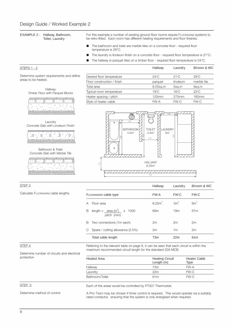
For this example a number of existing ground floor rooms require FLOORWARM systems tobe retro-fitted. Each room has different heating requirements and floor finishes.
● The bathroom and toilet are marble tiles on a concrete floor - required floortemperature is 29°C.
● The laundry is linoleum finish on a concrete floor - required floor temperature is 21°C.
● The hallway is parquet tiles on a timber floor - required floor temperature is 24°C.
Design Guide / Worked Example 2
EXAMPLE 2 - Hallway, Bathroom,Toilet, Laundry
STEPS 1 - 2
Determine system requirements and defineareas to be heated.
Hallway Laundry B/room & WC
Desired floor temperature 24oC 21oC 29oC
Floor construction / finish parquet linoleum marble tile
Total area 8.25sq.m 5sq.m 9sq.m
Typical room temperature 18oC 16oC 22oC
Heater spacing / pitch 120mm 275mm 160mm
Style of heater cable FW-A FW-C FW-C
STEP 3
Calculate FLOORWARM cable lengths
Hallway Laundry B/room & WC
FLOORWARM cable type FW-A FW-C FW-C
A Floor area 8.25m2
5m2
9m2
B length = area (m2) x 1000 69m 19m 57m
pitch (mm)
B Two connections (1m each) 2m 2m 2m
C Spare / cutting allowance (2.5%) 2m 1m 2m
Total cable length 73m 22m 61m
STEP 4
Determine number of circuits and electricalprotection
Referring to the relevant table on page 6, it can be seen that each circuit is within themaximum recommended circuit length for the standard 20A MCB.
Heated Area Heating Circuit Heater CableLength (m) Type
Hallway 73m FW-A
Laundry 22m FW-C
Bathroom/Toilet 61m FW-C
Each of the areas would be controlled by PT007 Thermostat.
A PRO TIMER may be chosen if timer control is required. This would operate via a suitablyrated contactor, ensuring that the system is only energised when required.
STEP 5
Determine method of control
8
Bathroom & ToiletConcrete Slab with Marble Tile
LaundryConcrete Slab with Linoleum Finish
HallwayTimber Floor with Parquet Blocks

Design Guide / Worked Example 2
STEP 6
Connection to electrical supply
The heating cables are terminated using TK/FW termination kits, complete with cold leads.Each cold lead is terminated into the wall mounted junction box using the plastic conduitordered separately.
Circuits may be connected to an electrical supply only if provided with a correctly ratedover-current and earth leakage protection device (MCB / RCD).
In this instance, a Heat Trace 3 way Local Distribution Panel (LDP03) is selected.
9
STEP 7
Determine power feed cable requirements
Determine power feed cables using the table provided in STEP 7 on page 6.
Design Guide / System Components
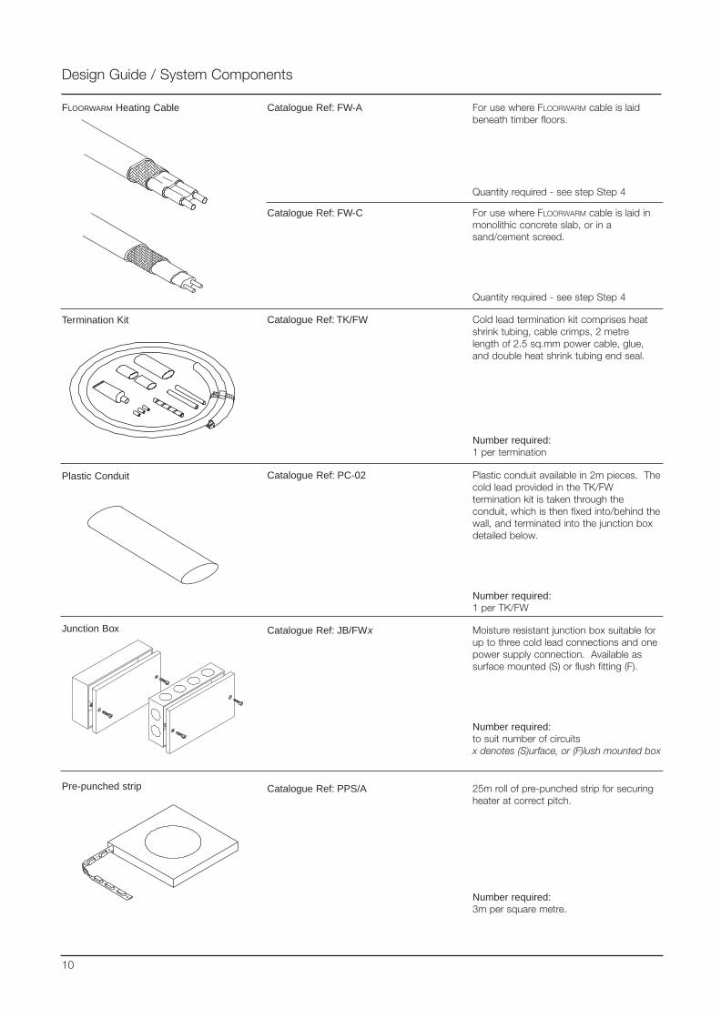
FLOORWARM Heating Cable
Termination Kit
Junction Box Moisture resistant junction box suitable forup to three cold lead connections and onepower supply connection. Available assurface mounted (S) or flush fitting (F).
Number required:to suit number of circuitsx denotes (S)urface, or (F)lush mounted box
Cold lead termination kit comprises heatshrink tubing, cable crimps, 2 metrelength of 2.5 sq.mm power cable, glue,and double heat shrink tubing end seal.
Number required:1 per termination
For use where FLOORWARM cable is laidbeneath timber floors.
Quantity required - see step Step 4
25m roll of pre-punched strip for securingheater at correct pitch.
Number required:3m per square metre.
Pre-punched strip
Catalogue Ref: FW-A
Catalogue Ref: TK/FW
Catalogue Ref: PPS/A
Catalogue Ref: JB/FWx
10
Catalogue Ref: FW-C For use where FLOORWARM cable is laid inmonolithic concrete slab, or in asand/cement screed.
Quantity required - see step Step 4
Plastic Conduit Plastic conduit available in 2m pieces. Thecold lead provided in the TK/FWtermination kit is taken through theconduit, which is then fixed into/behind thewall, and terminated into the junction boxdetailed below.
Number required:1 per TK/FW
Catalogue Ref: PC-02
Contactor Box
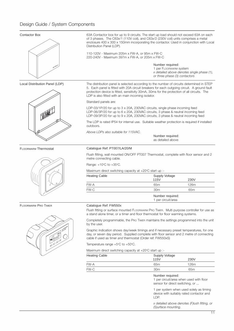
Local Distribution Panel (LDP) The distribution panel is selected according to the number of circuits determined in STEP5. Each panel is fitted with 20A circuit breakers for each outgoing circuit. A ground faultprotection device is fitted, sensitivity 30mA, 30ms for the protection of all circuits. TheLDP is also fitted with an main incoming isolator.
Standard panels are:
LDP-03/1P/20 for up to 3 x 20A, 230VAC circuits, single phase incoming feedLDP-06/3P/20 for up to 6 x 20A, 230VAC circuits, 3 phase & neutral incoming feedLDP-09/3P/20 for up to 9 x 20A, 230VAC circuits, 3 phase & neutral incoming feed
The LDP is rated IP54 for internal use. Suitable weather protection is required if installedoutdoors.
Above LDPs also suitable for 115VAC.Number required:as detailed above
FLOORWARM Thermostat
11
Flush fitting, wall mounted ON/OFF PT007 Thermostat, complete with floor sensor and 2metre connecting cable.
Range: +10oC to +35oC.
Maximum direct switching capacity at +20oC start up :-
Heating Cable Supply Voltage115V 230V
FW-A 65m 126m
FW-C 30m 65m
Number required:1 per circuit/area
Flush fitting or surface mounted FLOORWARM PRO TIMER. Multi purpose controller for use asa stand alone timer, or a timer and floor thermostat for floor warming systems.
Completely programmable, the PRO TIMER maintains the settings programmed into the unitby the user.
Graphic indication shows day/week timings and if necessary preset temperatures, for oneday, or seven day period. Supplied complete with floor sensor and 2 metre of connectingcable if used as timer and thermostat (Order ref: FW550xS)
Temperature range +5oC to +50oC.
Maximum direct switching capacity at +20oC start up :-
Heating Cable Supply Voltage115V 230V
FW-A 65m 126m
FW-C 30m 65m
Number required:1 per circuit/area when used with floorsensor for direct switching, or ...
1 per system when used solely as timingdevice with suitably rated contactor andLDP.
x detailed above denotes (F)lush fitting, or(S)urface mounting.
Design Guide / System Components
FLOORWARM PRO TIMER
Catalogue Ref: PT007/LA/20/M
Catalogue Ref: FW550x
63A Contactor box for up to 9 circuits. The start up load should not exceed 63A on eachof 3 phases. The C63x/1 (110V coil), and C63x/2 (230V coil) units comprises a metalenclosure 400 x 300 x 150mm incorporating the contactor. Used in conjunction with LocalDistribution Panel (LDP).
110-120V - Maximum 205m x FW-A, or 95m x FW-C220-240V - Maximum 397m x FW-A, or 205m x FW-C
Number required:1 per FLOORWARM systemx detailed above denotes single phase (1), or three phase (3) contactors
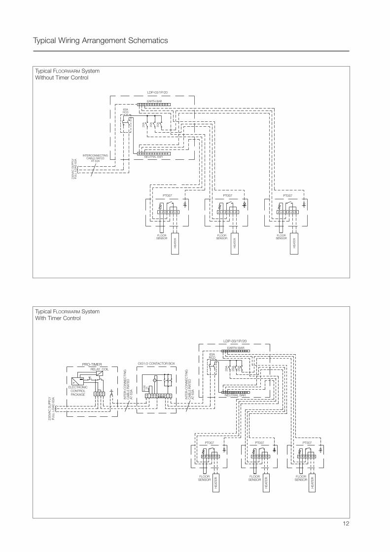
Typical Wiring Arrangement Schematics
Typical FLOORWARM SystemWithout Timer Control
Typical FLOORWARM SystemWith Timer Control
12
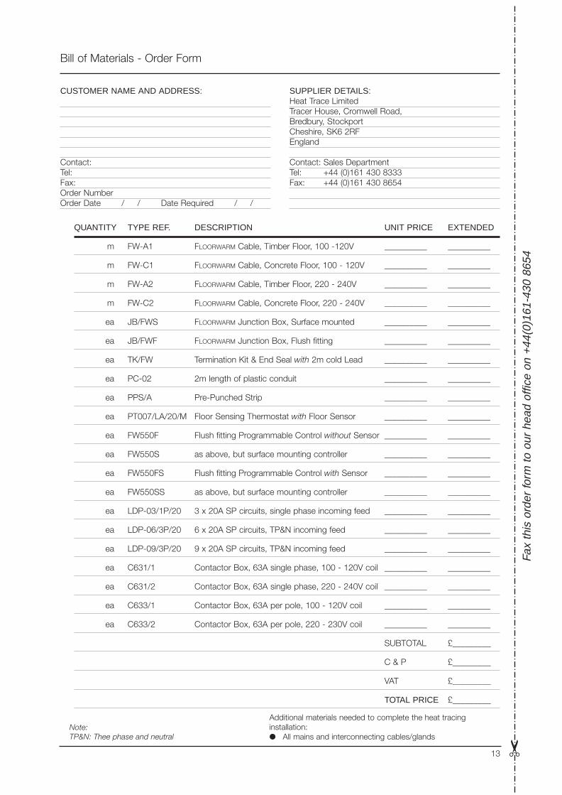
Bill of Materials - Order Form
Fax
this
ord
er fo
rm to
our
hea
d of
fice
on +
44(0
)161
-430
865
4
Additional materials needed to complete the heat tracinginstallation:● All mains and interconnecting cables/glands
QUANTITY TYPE REF. DESCRIPTION UNIT PRICE EXTENDED
m FW-A1 FLOORWARM Cable, Timber Floor, 100 -120V __________ __________
m FW-C1 FLOORWARM Cable, Concrete Floor, 100 - 120V __________ __________
m FW-A2 FLOORWARM Cable, Timber Floor, 220 - 240V __________ __________
m FW-C2 FLOORWARM Cable, Concrete Floor, 220 - 240V __________ __________
ea JB/FWS FLOORWARM Junction Box, Surface mounted __________ __________
ea JB/FWF FLOORWARM Junction Box, Flush fitting __________ __________
ea TK/FW Termination Kit & End Seal with 2m cold Lead __________ __________
ea PC-02 2m length of plastic conduit __________ __________
ea PPS/A Pre-Punched Strip __________ __________
ea PT007/LA/20/M Floor Sensing Thermostat with Floor Sensor __________ __________
ea FW550F Flush fitting Programmable Control without Sensor __________ __________
ea FW550S as above, but surface mounting controller __________ __________
ea FW550FS Flush fitting Programmable Control with Sensor __________ __________
ea FW550SS as above, but surface mounting controller __________ __________
ea LDP-03/1P/20 3 x 20A SP circuits, single phase incoming feed __________ __________
ea LDP-06/3P/20 6 x 20A SP circuits, TP&N incoming feed __________ __________
ea LDP-09/3P/20 9 x 20A SP circuits, TP&N incoming feed __________ __________
ea C631/1 Contactor Box, 63A single phase, 100 - 120V coil __________ __________
ea C631/2 Contactor Box, 63A single phase, 220 - 240V coil __________ __________
ea C633/1 Contactor Box, 63A per pole, 100 - 120V coil __________ __________
ea C633/2 Contactor Box, 63A per pole, 220 - 230V coil __________ __________
SUBTOTAL £_________
C & P £_________
VAT £_________
TOTAL PRICE £_________
CUSTOMER NAME AND ADDRESS:
Contact:Tel:Fax:Order NumberOrder Date / / Date Required / /
SUPPLIER DETAILS:Heat Trace LimitedTracer House, Cromwell Road,Bredbury, StockportCheshire, SK6 2RFEngland
Contact: Sales DepartmentTel: +44 (0)161 430 8333Fax: +44 (0)161 430 8654
13 ✂
Note:TP&N: Thee phase and neutral

The information given herein, including drawings, illustrations and schematics (which are intended for illustration purposes only), is believed to be reliable. However, Heat Trace Ltd makes nowarranties as to its accuracy or completeness and disclaims any liability in connection with its use. Users of Heat Trace Ltd products should make their own evaluation to determine the suitabilityof each such product for specific applications. In no way will Heat Trace Ltd be liable for any damages arising out of the misuse, resale or use of the product.
PD
G06
0 06
/00
Presented by:
BS EN ISO 9001 Certificate No. 0160
Mere's Edge, Chester Road, Helsby, Frodsham, Cheshire, WA6 0DJ, UK.Tel: +44 (0)1928 726 451 Fax: +44 (0)1928 727 846 www.heat-trace.com