Embed Size (px)
Citation preview
SELF-STEERING AXLE
OPERATING AND MAINTENANCE MANUAL
Self steering axles - Operating and maintenance manual
Number MAN0032
Date of Compilation 15/04/2010
Date of Review
Table of contents 0
Page 2 of 38
Self-steering axle - Operating and maintenance manu al
Contents of the manual
SECTION 01 – INTRODUCTION TO SELF STEERING AXLE 1.1 Operating principle
1.2 Basic components
1.3 Technical appendix
SECTION 02 - GENERAL INFORMATION
2.1 General information
2.2 Installation
2.3 Checking procedures
SECTION 03 - AXLE BODY USE AND MAINTENANCE
3.1 Disassembly and reassembly of critical components
3.2 Adjustment
3.3 Lubrication
3.4 Periodic maintenance
3.5 Tightening torques
3.6 Contact in case of problems
This operating and maintenance manual is an integral part of technical documentation relative to the SELF-STEERING AXLE. The manual must be preserved with care and made known and available to all interested parties. Read this sections with care before performing maintenance on the self-steering axle. This will improve the safety conditions and reliability of the interventions that are performed. For brakes/suspensions informations see the manufacturer manual.
WARNING Maintenance procedures must only be performed by duly qualified and authorized personnel.
Self steering axles - Operating and maintenance manual
Number MAN0032
Date of Compilation 15/04/2010
Date of Review
Table of contents 0
Page 3 of 38
Self-steering axle - Operating and maintenance manu al
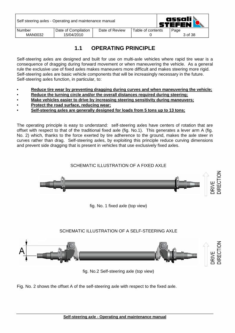
1.1 OPERATING PRINCIPLE Self-steering axles are designed and built for use on multi-axle vehicles where rapid tire wear is a consequence of dragging during forward movement or when maneuvering the vehicle. As a general rule the exclusive use of fixed axles makes maneuvers more difficult and makes steering more rigid. Self-steering axles are basic vehicle components that will be increasingly necessary in the future. Self-steering axles function, in particular, to: • Reduce tire wear by preventing dragging during curv es and when maneuvering the vehicle; • Reduce the turning circle and/or the overall distan ces required during steering; • Make vehicles easier to drive by increasing steerin g sensitivity during maneuvers; • Protect the road surface, reducing wear; • Self-steering axles are generally designed for load s from 5 tons up to 13 tons; The operating principle is easy to understand: self-steering axles have centers of rotation that are offset with respect to that of the traditional fixed axle (fig. No.1). This generates a lever arm A (fig. No. 2) which, thanks to the force exerted by tire adherence to the ground, makes the axle steer in curves rather than drag. Self-steering axles, by exploiting this principle reduce curving dimensions and prevent side dragging that is present in vehicles that use exclusively fixed axles.
SCHEMATIC ILLUSTRATION OF A FIXED AXLE
fig. No. 1 fixed axle (top view)
SCHEMATIC ILLUSTRATION OF A SELF-STEERING AXLE
fig. No.2 Self-steering axle (top view)
Fig. No. 2 shows the offset A of the self-steering axle with respect to the fixed axle.
Self steering axles - Operating and maintenance manual
Number MAN0032
Date of Compilation 15/04/2010
Date of Review
Table of contents 0
Page 4 of 38
Self-steering axle - Operating and maintenance manu al
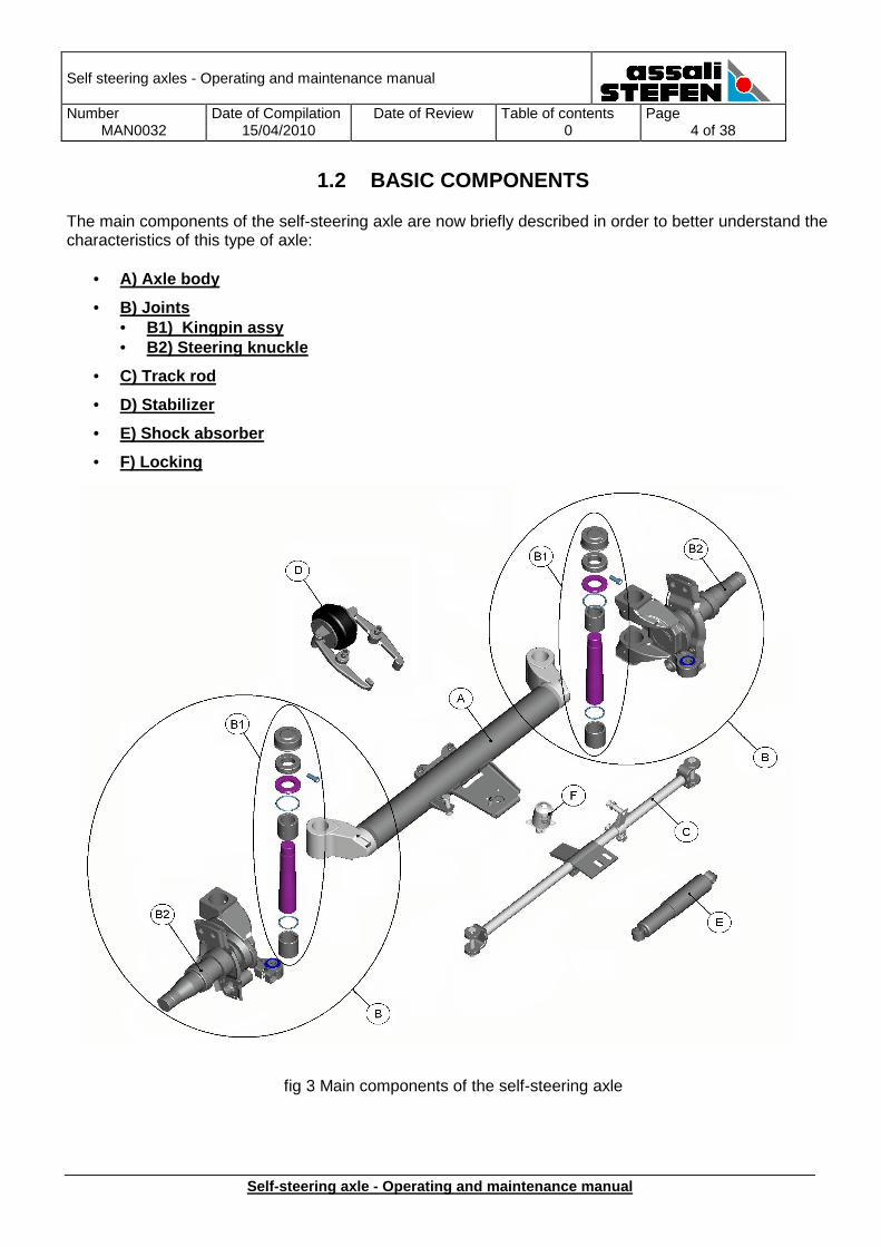
1.2 BASIC COMPONENTS The main components of the self-steering axle are now briefly described in order to better understand the characteristics of this type of axle:
• A) Axle body
• B) Joints • B1) Kingpin assy • B2) Steering knuckle
• C) Track rod
• D) Stabilizer
• E) Shock absorber
• F) Locking
fig 3 Main components of the self-steering axle
Self steering axles - Operating and maintenance manual
Number MAN0032
Date of Compilation 15/04/2010
Date of Review
Table of contents 0
Page 5 of 38
Self-steering axle - Operating and maintenance manu al
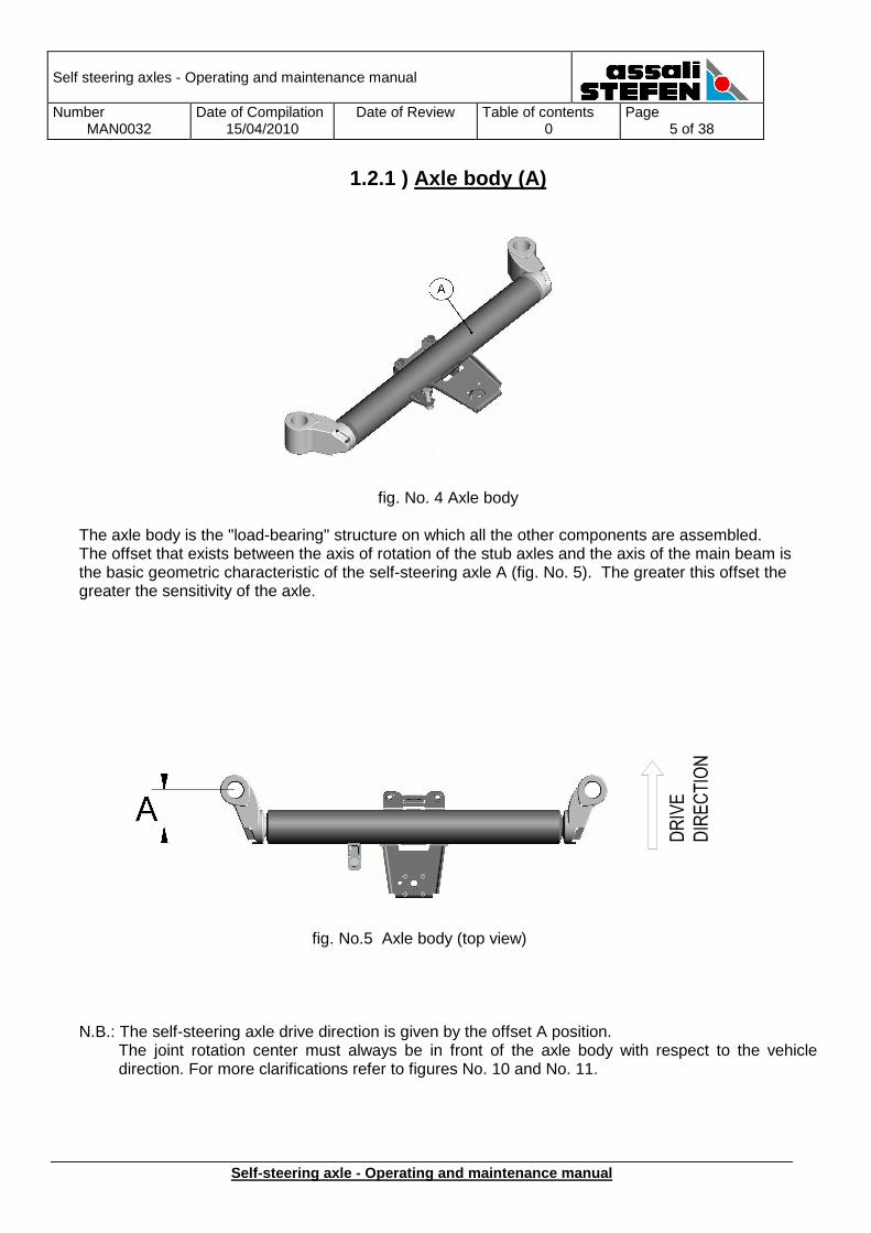
1.2.1 ) Axle body (A)
fig. No. 4 Axle body The axle body is the "load-bearing" structure on which all the other components are assembled. The offset that exists between the axis of rotation of the stub axles and the axis of the main beam is the basic geometric characteristic of the self-steering axle A (fig. No. 5). The greater this offset the greater the sensitivity of the axle.
fig. No.5 Axle body (top view)
N.B.: The self-steering axle drive direction is given by the offset A position. The joint rotation center must always be in front of the axle body with respect to the vehicle direction. For more clarifications refer to figures No. 10 and No. 11.
Self steering axles - Operating and maintenance manual
Number MAN0032
Date of Compilation 15/04/2010
Date of Review
Table of contents 0
Page 6 of 38
Self-steering axle - Operating and maintenance manu al
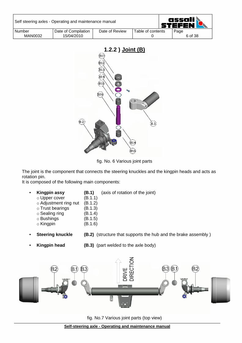
1.2.2 ) Joint (B)
fig. No. 6 Various joint parts The joint is the component that connects the steering knuckles and the kingpin heads and acts as rotation pin. It is composed of the following main components:
• Kingpin assy (B.1) (axis of rotation of the joint) o Upper cover (B.1.1) o Adjustment ring nut (B.1.2) o Trust bearings (B.1.3) o Sealing ring (B.1.4) o Bushings (B.1.5) o Kingpin (B.1.6)
• Steering knuckle (B.2) (structure that supports the hub and the brake assembly )
• Kingpin head (B.3) (part welded to the axle body)
fig. No.7 Various joint parts (top view)
Self steering axles - Operating and maintenance manual
Number MAN0032
Date of Compilation 15/04/2010
Date of Review
Table of contents 0
Page 7 of 38
Self-steering axle - Operating and maintenance manu al
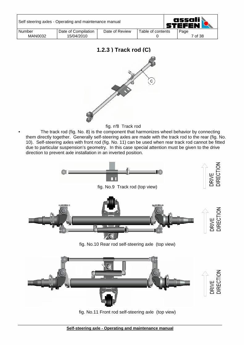
1.2.3 ) Track rod (C)
fig. n°8 Track rod • The track rod (fig. No. 8) is the component that harmonizes wheel behavior by connecting
them directly together. Generally self-steering axles are made with the track rod to the rear (fig. No. 10). Self-steering axles with front rod (fig. No. 11) can be used when rear track rod cannot be fitted due to particular suspension’s geometry. In this case special attention must be given to the drive direction to prevent axle installation in an inverted position.
fig. No.9 Track rod (top view)
fig. No.10 Rear rod self-steering axle (top view)
fig. No.11 Front rod self-steering axle (top view)
Self steering axles - Operating and maintenance manual
Number MAN0032
Date of Compilation 15/04/2010
Date of Review
Table of contents 0
Page 8 of 38
Self-steering axle - Operating and maintenance manu al
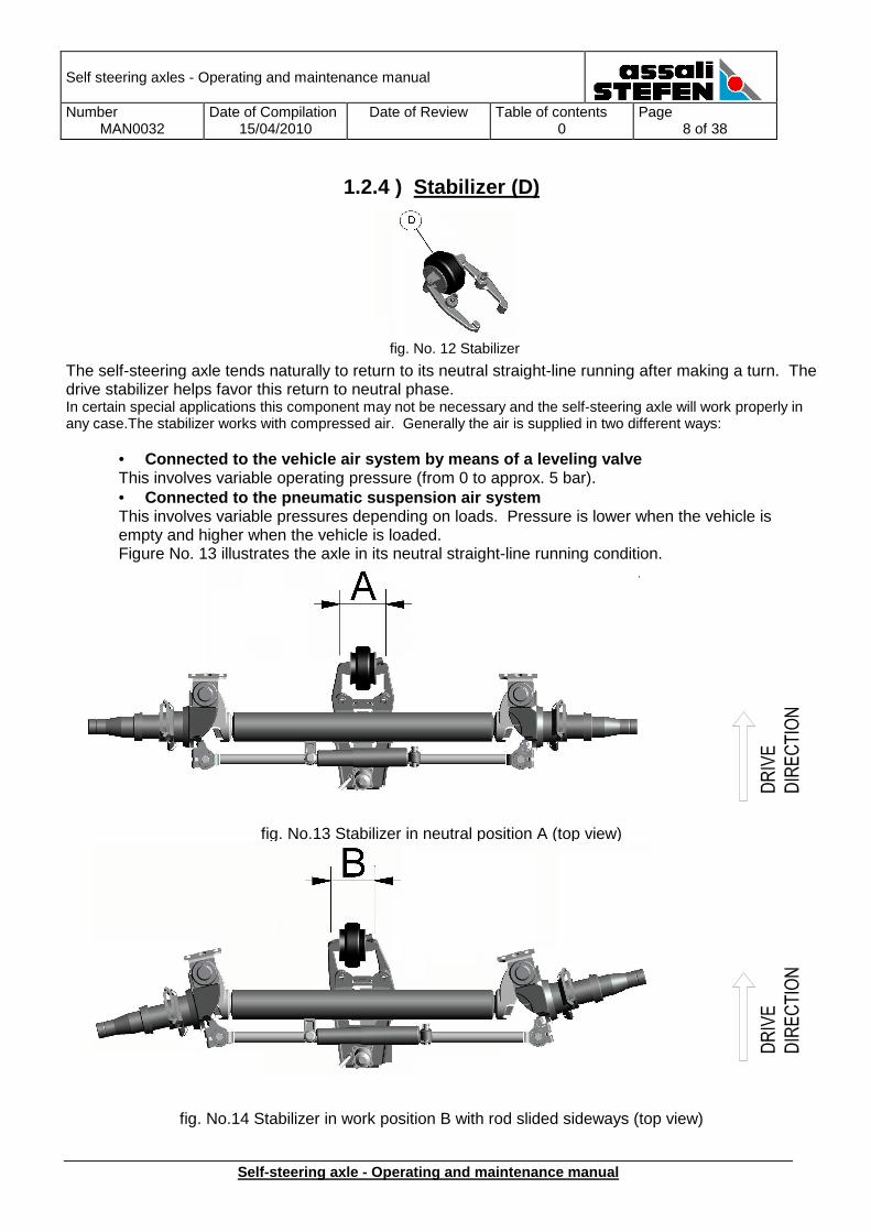
1.2.4 ) Stabilizer (D)
fig. No. 12 Stabilizer
The self-steering axle tends naturally to return to its neutral straight-line running after making a turn. The drive stabilizer helps favor this return to neutral phase. In certain special applications this component may not be necessary and the self-steering axle will work properly in any case.The stabilizer works with compressed air. Generally the air is supplied in two different ways:
• Connected to the vehicle air system by means of a l eveling valve This involves variable operating pressure (from 0 to approx. 5 bar). • Connected to the pneumatic suspension air system This involves variable pressures depending on loads. Pressure is lower when the vehicle is empty and higher when the vehicle is loaded. Figure No. 13 illustrates the axle in its neutral straight-line running condition. Figure No. 14 illustrates the axle when steering with the track rod moved.
fig. No.13 Stabilizer in neutral position A (top view)
fig. No.14 Stabilizer in work position B with rod slided sideways (top view)
Self steering axles - Operating and maintenance manual
Number MAN0032
Date of Compilation 15/04/2010
Date of Review
Table of contents 0
Page 9 of 38
Self-steering axle - Operating and maintenance manu al
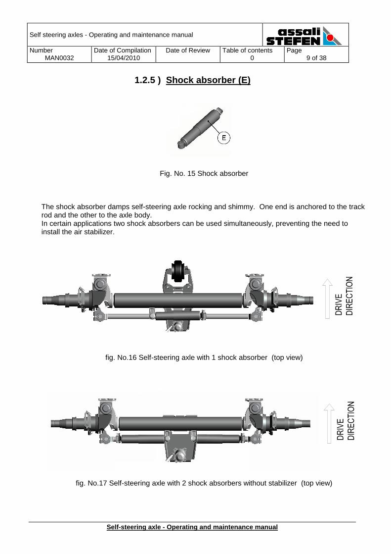
1.2.5 ) Shock absorber (E)
Fig. No. 15 Shock absorber
The shock absorber damps self-steering axle rocking and shimmy. One end is anchored to the track rod and the other to the axle body. In certain applications two shock absorbers can be used simultaneously, preventing the need to install the air stabilizer.
fig. No.16 Self-steering axle with 1 shock absorber (top view)
fig. No.17 Self-steering axle with 2 shock absorbers without stabilizer (top view)
Self steering axles - Operating and maintenance manual
Number MAN0032
Date of Compilation 15/04/2010
Date of Review
Table of contents 0
Page 10 of 38
Self-steering axle - Operating and maintenance manu al
1.2.6 ) Locking (F)
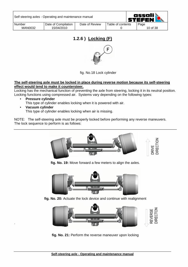
fig. No.18 Lock cylinder
The self-steering axle must be locked in place duri ng reverse motion because its self-steering effect would tend to make it countersteer. Locking has the mechanical function of preventing the axle from steering, locking it in its neutral position. Locking functions using compressed air. Systems vary depending on the following types:
• Pressure cylinder This type of cylinder enables locking when it is powered with air.
• Vacuum cylinder This type of cylinder enables locking when air is missing.
NOTE: The self-steering axle must be properly locked before performing any reverse maneuvers. The lock sequence to perform is as follows:
fig. No. 19: Move forward a few meters to align the axles.
fig. No. 20: Actuate the lock device and continue with realignment
.
fig. No. 21: Perform the reverse maneuver upon locking
Self steering axles - Operating and maintenance manual
Number MAN0032
Date of Compilation 15/04/2010
Date of Review
Table of contents 0
Page 11 of 38
Self-steering axle - Operating and maintenance manu al
1.3 TECHNICAL APPENDIX
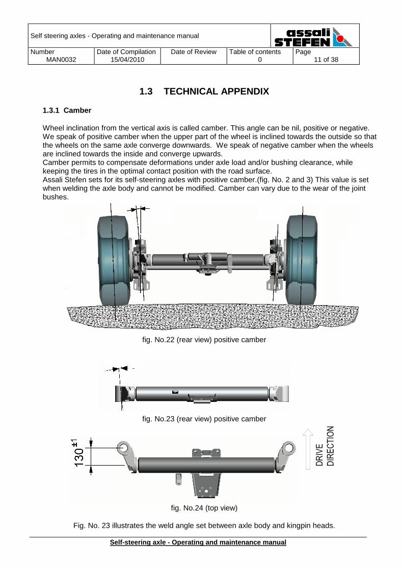
1.3.1 Camber Wheel inclination from the vertical axis is called camber. This angle can be nil, positive or negative. We speak of positive camber when the upper part of the wheel is inclined towards the outside so that the wheels on the same axle converge downwards. We speak of negative camber when the wheels are inclined towards the inside and converge upwards. Camber permits to compensate deformations under axle load and/or bushing clearance, while keeping the tires in the optimal contact position with the road surface. Assali Stefen sets for its self-steering axles with positive camber.(fig. No. 2 and 3) This value is set when welding the axle body and cannot be modified. Camber can vary due to the wear of the joint bushes.
fig. No.22 (rear view) positive camber
fig. No.23 (rear view) positive camber
fig. No.24 (top view)
Fig. No. 23 illustrates the weld angle set between axle body and kingpin heads.
Self steering axles - Operating and maintenance manual
Number MAN0032
Date of Compilation 15/04/2010
Date of Review
Table of contents 0
Page 12 of 38
Self-steering axle - Operating and maintenance manu al
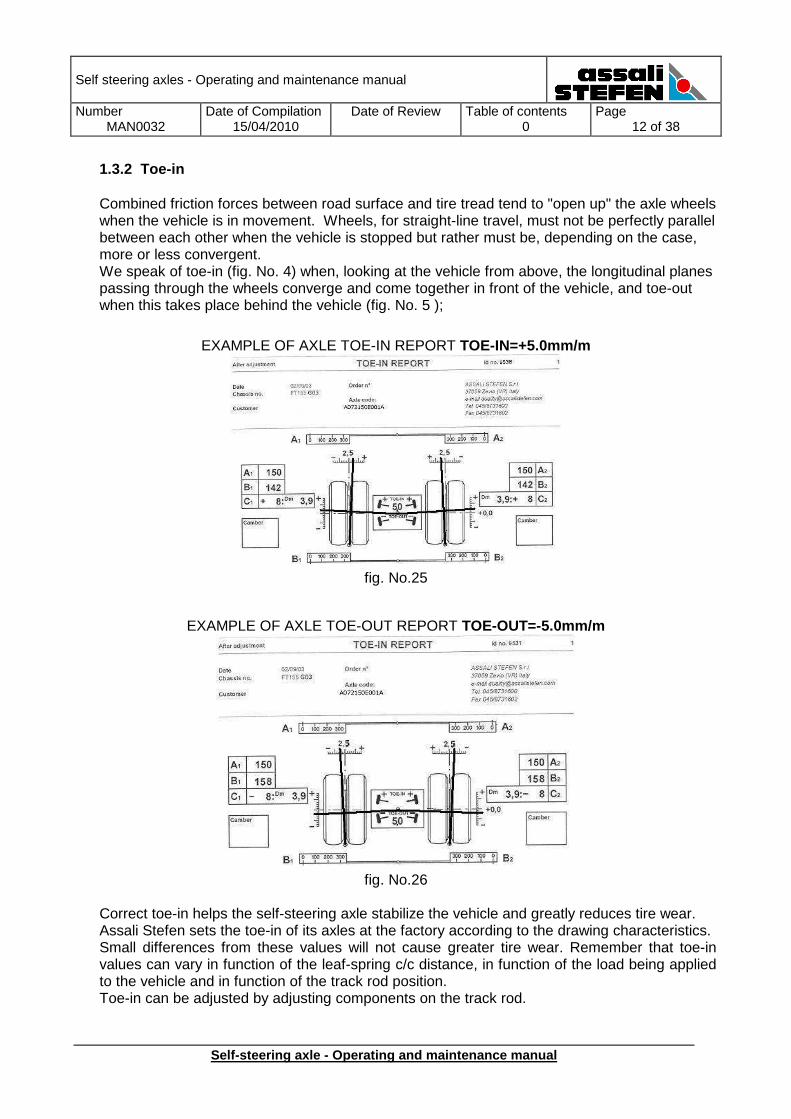
1.3.2 Toe-in Combined friction forces between road surface and tire tread tend to "open up" the axle wheels when the vehicle is in movement. Wheels, for straight-line travel, must not be perfectly parallel between each other when the vehicle is stopped but rather must be, depending on the case, more or less convergent. We speak of toe-in (fig. No. 4) when, looking at the vehicle from above, the longitudinal planes passing through the wheels converge and come together in front of the vehicle, and toe-out when this takes place behind the vehicle (fig. No. 5 );
EXAMPLE OF AXLE TOE-IN REPORT TOE-IN=+5.0mm/m
fig. No.25
EXAMPLE OF AXLE TOE-OUT REPORT TOE-OUT=-5.0mm/m
fig. No.26
Correct toe-in helps the self-steering axle stabilize the vehicle and greatly reduces tire wear. Assali Stefen sets the toe-in of its axles at the factory according to the drawing characteristics. Small differences from these values will not cause greater tire wear. Remember that toe-in values can vary in function of the leaf-spring c/c distance, in function of the load being applied to the vehicle and in function of the track rod position. Toe-in can be adjusted by adjusting components on the track rod.
Self steering axles - Operating and maintenance manual
Number MAN0032
Date of Compilation 15/04/2010
Date of Review
Table of contents 0
Page 13 of 38
Self-steering axle - Operating and maintenance manu al
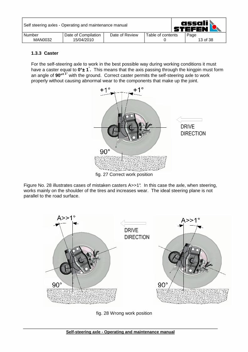
1.3.3 Caster For the self-steering axle to work in the best possible way during working conditions it must have a caster equal to 0°±±±± 1°. This means that the axis passing through the kingpin must form an angle of 90°±±±± 1° with the ground. Correct caster permits the self-steering axle to work properly without causing abnormal wear to the components that make up the joint.
fig. 27 Correct work position Figure No. 28 illustrates cases of mistaken casters A>>1°. In this case the axle, when steering, works mainly on the shoulder of the tires and increases wear. The ideal steering plane is not parallel to the road surface.
fig. 28 Wrong work position
Self steering axles - Operating and maintenance manual
Number MAN0032
Date of Compilation 15/04/2010
Date of Review
Table of contents 0
Page 14 of 38
Self-steering axle - Operating and maintenance manu al
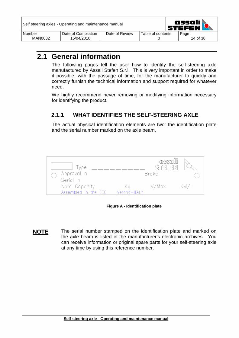
2.1 General information The following pages tell the user how to identify the self-steering axle manufactured by Assali Stefen S.r.l. This is very important in order to make it possible, with the passage of time, for the manufacturer to quickly and correctly furnish the technical information and support required for whatever need.
We highly recommend never removing or modifying information necessary for identifying the product.
2.1.1 WHAT IDENTIFIES THE SELF-STEERING AXLE
The actual physical identification elements are two: the identification plate and the serial number marked on the axle beam.
Figure A - Identification plate
NOTE The serial number stamped on the identification plate and marked on the axle beam is listed in the manufacturer’s electronic archives. You can receive information or original spare parts for your self-steering axle at any time by using this reference number.
Self steering axles - Operating and maintenance manual
Number MAN0032
Date of Compilation 15/04/2010
Date of Review
Table of contents 0
Page 15 of 38
Self-steering axle - Operating and maintenance manu al
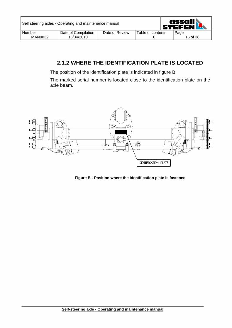
2.1.2 WHERE THE IDENTIFICATION PLATE IS LOCATED
The position of the identification plate is indicated in figure B
The marked serial number is located close to the identification plate on the axle beam.
Figure B - Position where the identification plate is fastened
Self steering axles - Operating and maintenance manual
Number MAN0032
Date of Compilation 15/04/2010
Date of Review
Table of contents 0
Page 16 of 38
Self-steering axle - Operating and maintenance manu al
2.2 Installation
2.2.1 STATEMENT OF PRODUCT USE AND PURPOSE
The self-steering axle is a product conceived and manufactured for multiple-axle vehicles where the side scrub, during on-road travel or when making turns, translates into sudden tire deterioration or greater tire wear. In general this also means greater turning difficulties and greater “steering stiffness”.
The self-steering axle is a fundamental part of your vehicle which will be difficult for you to do without in the future. Self-steering axles, in particular, have the following advantages:
• Increase the load-bearing capacity of the vehicle by acting as additional axles.
• Reduce tire wear.
• Prevent scrubbing of tires during steering manoeuvers.
• Protect road surfaces.
• Make it easier to drive the vehicle.
• Make steering more sensitive.
• Reduce the space required for manoeuvering the vehicle.
• Elimates fuel waste
Self steering axles - Operating and maintenance manual
Number MAN0032
Date of Compilation 15/04/2010
Date of Review
Table of contents 0
Page 17 of 38
Self-steering axle - Operating and maintenance manu al
2.2.2 INSTALLING THE SELF-STEERING AXLE
Assembly procedures can create danger situations for exposed persons. It is ABSOLUTELY NECESSARY to keep to the recommendations of Assali Stefen S.r.l. given in this manual, and to use properly inspected and suitable equipment and tools.
Installation personnel must be trained and authorized to use tools and test equipment.
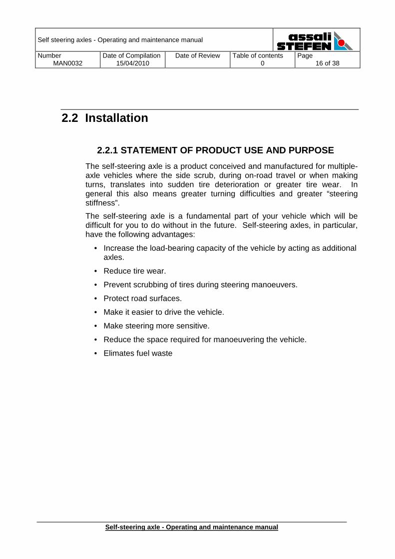
Self-steering axles must be installed correctly: deviation from established dimensions can compromise the self-steering effect. The axle, in its “at-rest” position, must take the position shown in figure c:
Figure C - Inclination of the stub axle pin
NOTE Inclination tolerance ±1° from the vertical positio n.
Self steering axles - Operating and maintenance manual
Number MAN0032
Date of Compilation 15/04/2010
Date of Review
Table of contents 0
Page 18 of 38
Self-steering axle - Operating and maintenance manu al
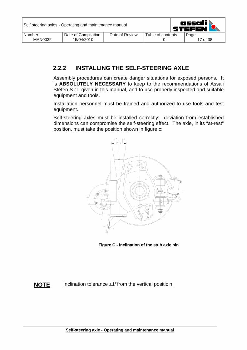
2.2.3 WELDING THE SPRING SEATS/SUSPENSION ARMS
It is important to check the working position of the air suspension in order to weld the spring seats/ suspension arms at the correct angle, with the stub axle pin vertical as illustrated below.
Figure D - Inclination of the spring seats
This operation, performed correctly, permits the axle to function properly and will not damage any component.
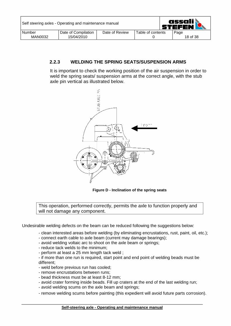
Undesirable welding defects on the beam can be reduced following the suggestions below:
- clean interested areas before welding (by eliminating encrustations, rust, paint, oil, etc.); - connect earth cable to axle beam (current may damage bearings); - avoid welding voltaic arc to shoot on the axle beam or springs; - reduce tack welds to the minimum; - perform at least a 25 mm length tack weld ; - if more than one run is required, start point and end point of welding beads must be different; - weld before previous run has cooled; - remove encrustations between runs; - bead thickness must be at least 8-12 mm; - avoid crater forming inside beads. Fill up craters at the end of the last welding run; - avoid welding scums on the axle beam and springs; - remove welding scums before painting (this expedient will avoid future parts corrosion).
Self steering axles - Operating and maintenance manual
Number MAN0032
Date of Compilation 15/04/2010
Date of Review
Table of contents 0
Page 19 of 38
Self-steering axle - Operating and maintenance manu al
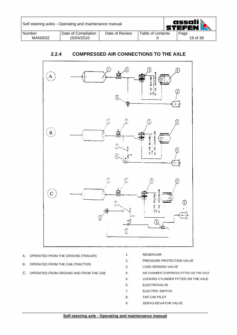
2.2.4 COMPRESSED AIR CONNECTIONS TO THE AXLE
A. OPERATED FROM THE GROUND (TRAILER)
B. OPERATED FROM THE CAB (TRACTOR)
C. OPERATED FROM GROUND AND FROM THE CAB
1. RESERVOIR
2. PRESSURE PROTECTION VALVE
3. LOAD SENSING VALVE
4. AIR CHAMBER (TORPRESS) FITTED ON THE AXLE
5. LOCKING CYLINDER FITTED ON THE AXLE
6. ELECTROVALVE
7. ELECTRIC SWITCH
8. TAP C/W PILOT
9. SERVO-DEVIATOR VALVE
Self steering axles - Operating and maintenance manual
Number MAN0032
Date of Compilation 15/04/2010
Date of Review
Table of contents 0
Page 20 of 38
Self-steering axle - Operating and maintenance manu al
2.3 Checking procedures
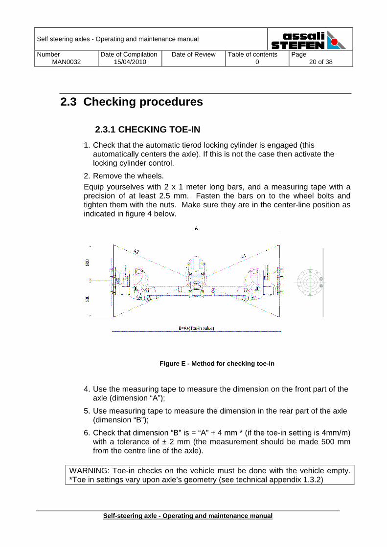
2.3.1 CHECKING TOE-IN
1. Check that the automatic tierod locking cylinder is engaged (this automatically centers the axle). If this is not the case then activate the locking cylinder control.
2. Remove the wheels. Equip yourselves with 2 x 1 meter long bars, and a measuring tape with a precision of at least 2.5 mm. Fasten the bars on to the wheel bolts and tighten them with the nuts. Make sure they are in the center-line position as indicated in figure 4 below.
Figure E - Method for checking toe-in
4. Use the measuring tape to measure the dimension on the front part of the axle (dimension “A”);
5. Use measuring tape to measure the dimension in the rear part of the axle (dimension “B”);
6. Check that dimension “B” is = “A” + 4 mm * (if the toe-in setting is 4mm/m) with a tolerance of ± 2 mm (the measurement should be made 500 mm from the centre line of the axle).
WARNING: Toe-in checks on the vehicle must be done with the vehicle empty. *Toe in settings vary upon axle’s geometry (see technical appendix 1.3.2)
Self steering axles - Operating and maintenance manual
Number MAN0032
Date of Compilation 15/04/2010
Date of Review
Table of contents 0
Page 21 of 38
Self-steering axle - Operating and maintenance manu al
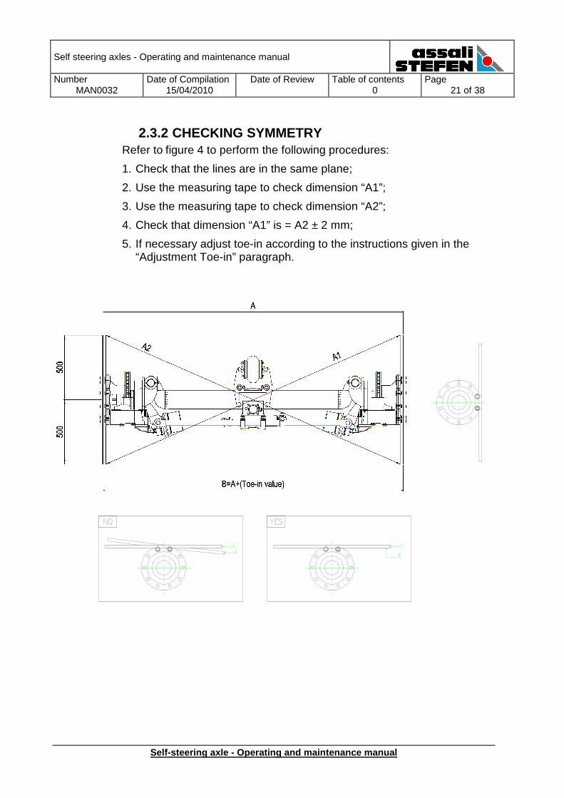
2.3.2 CHECKING SYMMETRY Refer to figure 4 to perform the following procedures:
1. Check that the lines are in the same plane;
2. Use the measuring tape to check dimension “A1”;
3. Use the measuring tape to check dimension “A2”;
4. Check that dimension “A1” is = A2 ± 2 mm;
5. If necessary adjust toe-in according to the instructions given in the “Adjustment Toe-in” paragraph.
Self steering axles - Operating and maintenance manual
Number MAN0032
Date of Compilation 15/04/2010
Date of Review
Table of contents 0
Page 22 of 38
Self-steering axle - Operating and maintenance manu al
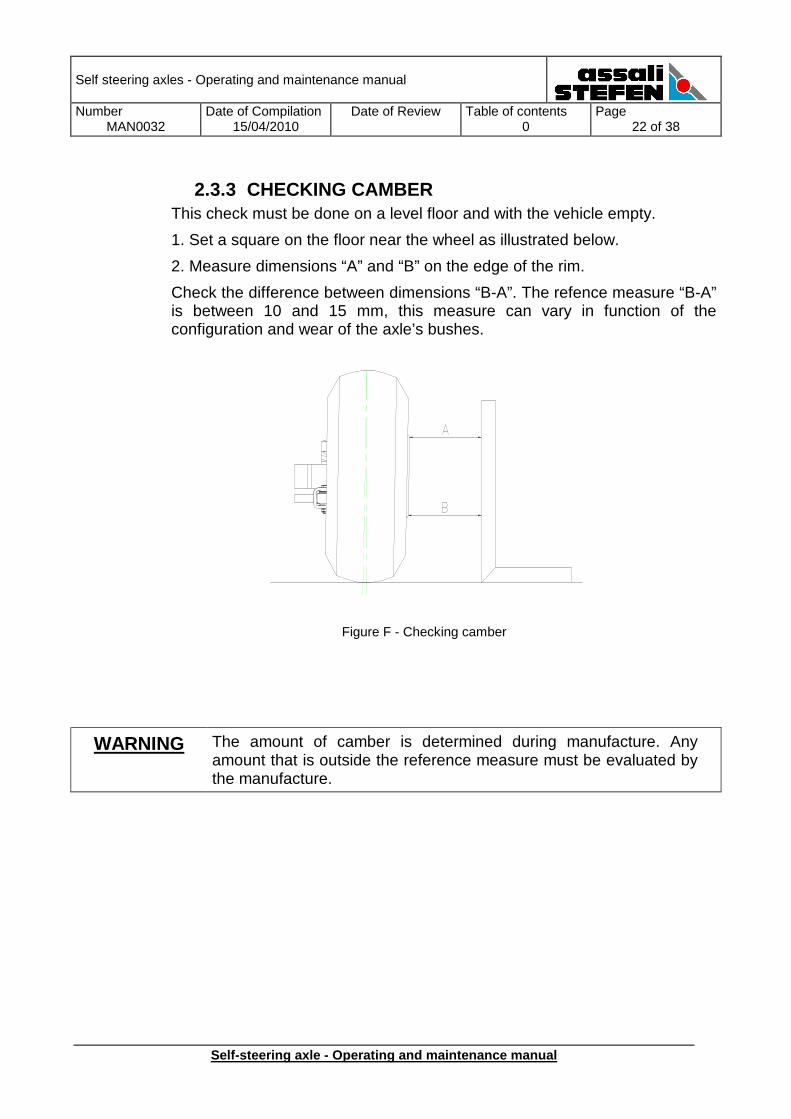
2.3.3 CHECKING CAMBER
This check must be done on a level floor and with the vehicle empty.
1. Set a square on the floor near the wheel as illustrated below.
2. Measure dimensions “A” and “B” on the edge of the rim.
Check the difference between dimensions “B-A”. The refence measure “B-A” is between 10 and 15 mm, this measure can vary in function of the configuration and wear of the axle’s bushes.
Figure F - Checking camber
WARNING The amount of camber is determined during manufacture. Any amount that is outside the reference measure must be evaluated by the manufacture.
Self steering axles - Operating and maintenance manual
Number MAN0032
Date of Compilation 15/04/2010
Date of Review
Table of contents 0
Page 23 of 38
Self-steering axle - Operating and maintenance manu al
3.1 Disassembly and reassembly of critical components
WARNING All disassembly and reassembly procedures must be performed:
a) with the machine perfectly stopped
b) in a working environment properly equipped with all necessary tools and without any dangerous situations c) carefully clean each component prior to reassembly. Degrease or lubricate depending on the component’s function.
3.1.1 STUB AXLE PIN DISASSEMBLY
Replacement of the stub axle pin requires disassembly of the axle from the vehicle.
The sequence of procedures and the estimated stub axle pin disassembly and reassembly time, performed by trained personnel, are as follows:
Description of procedure Time in minutes
Axle disassembly 60’
Axle reassembly 50’
Stub axle pin reassembly 50’
Toe-in 30’
TOTAL PROCEDURE TIME 190’
3.1.2 AXLE DISASSEMBLY
1. Check that the automatic tierod locking cylinder is engaged. Otherwise activate the locking control.
2. Lift the rear of the vehicle until the wheels are slightly raised off the floor. 3. Place strong support struts under the axle. 4. Loosen the wheel nuts. 5. Remove the wheels. 6. Uniformly lift the rear part of the vehicle. 7. Loosen the axle fastening U-bolts. 8. Remove the axle from the suspension arms.
Self steering axles - Operating and maintenance manual
Number MAN0032
Date of Compilation 15/04/2010
Date of Review
Table of contents 0
Page 24 of 38
Self-steering axle - Operating and maintenance manu al
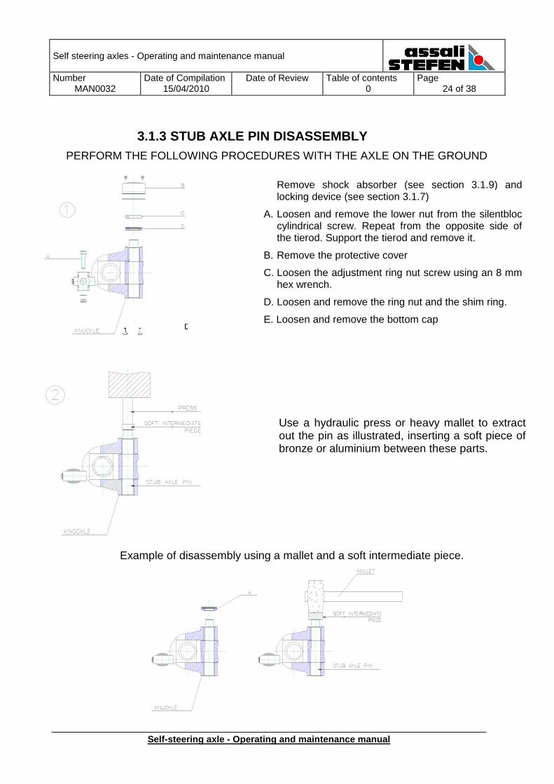
3.1.3 STUB AXLE PIN DISASSEMBLY PERFORM THE FOLLOWING PROCEDURES WITH THE AXLE ON THE GROUND
Example of disassembly using a mallet and a soft intermediate piece.
Remove shock absorber (see section 3.1.9) and locking device (see section 3.1.7)
A. Loosen and remove the lower nut from the silentbloccylindrical screw. Repeat from the opposite side of the tierod. Support the tierod and remove it.
B. Remove the protective cover
C. Loosen the adjustment ring nut screw using an 8 mm hex wrench.
D. Loosen and remove the ring nut and the shim ring.
E. Loosen and remove the bottom cap
Use a hydraulic press or heavy mallet to extract out the pin as illustrated, inserting a soft piece of bronze or aluminium between these parts.
Self steering axles - Operating and maintenance manual
Number MAN0032
Date of Compilation 15/04/2010
Date of Review
Table of contents 0
Page 25 of 38
Self-steering axle - Operating and maintenance manu al
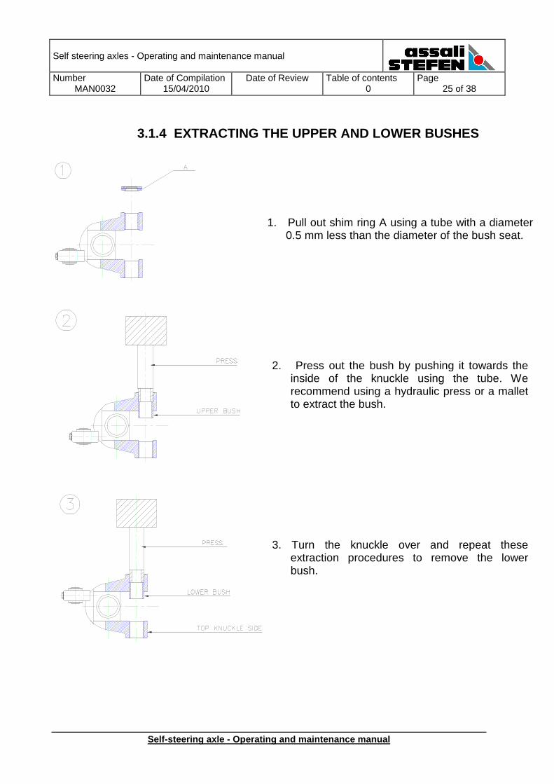
3.1.4 EXTRACTING THE UPPER AND LOWER BUSHES
1. Pull out shim ring A using a tube with a diameter 0.5 mm less than the diameter of the bush seat.
2. Press out the bush by pushing it towards the inside of the knuckle using the tube. We recommend using a hydraulic press or a mallet to extract the bush.
3. Turn the knuckle over and repeat these extraction procedures to remove the lower bush.
Self steering axles - Operating and maintenance manual
Number MAN0032
Date of Compilation 15/04/2010
Date of Review
Table of contents 0
Page 26 of 38
Self-steering axle - Operating and maintenance manu al
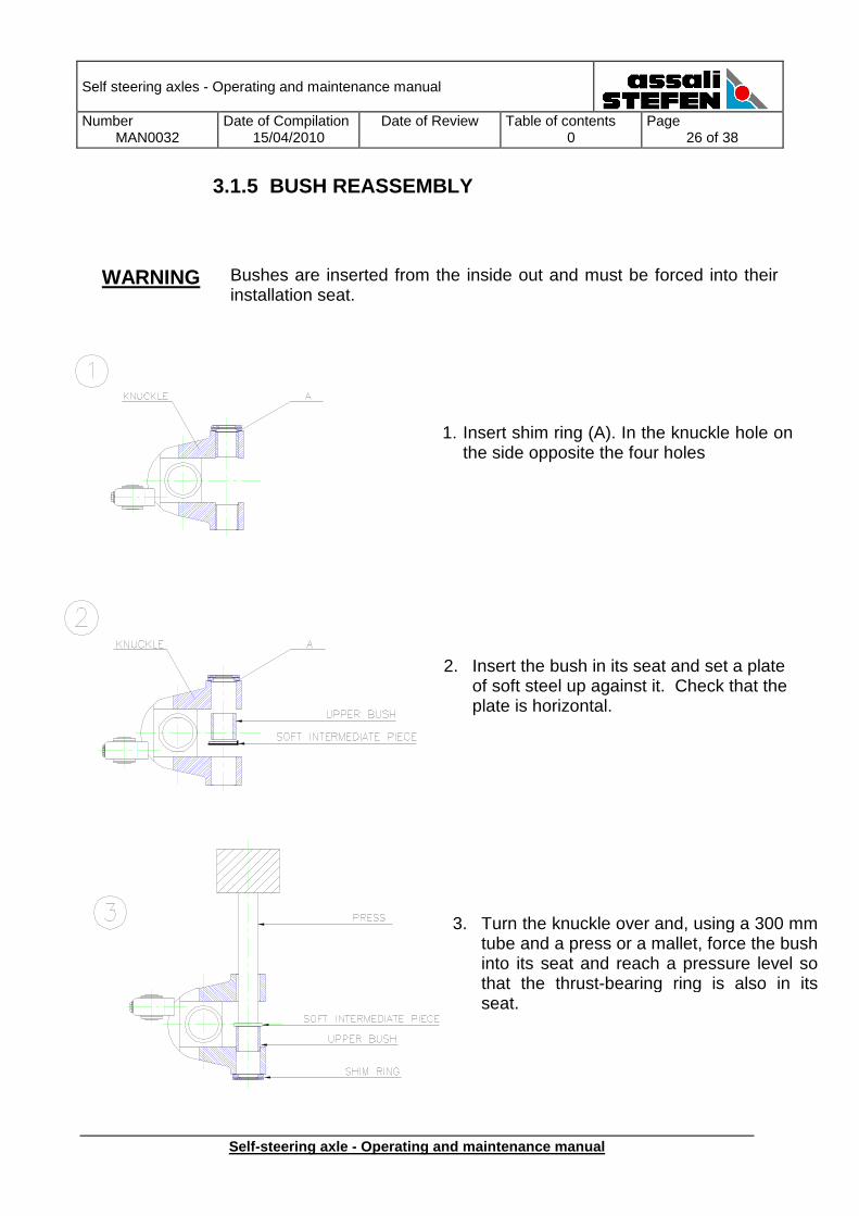
3.1.5 BUSH REASSEMBLY
WARNING Bushes are inserted from the inside out and must be forced into their installation seat.
1. Insert shim ring (A). In the knuckle hole on the side opposite the four holes
2. Insert the bush in its seat and set a plate of soft steel up against it. Check that the plate is horizontal.
3. Turn the knuckle over and, using a 300 mm tube and a press or a mallet, force the bush into its seat and reach a pressure level so that the thrust-bearing ring is also in its seat.
Self steering axles - Operating and maintenance manual
Number MAN0032
Date of Compilation 15/04/2010
Date of Review
Table of contents 0
Page 27 of 38
Self-steering axle - Operating and maintenance manu al
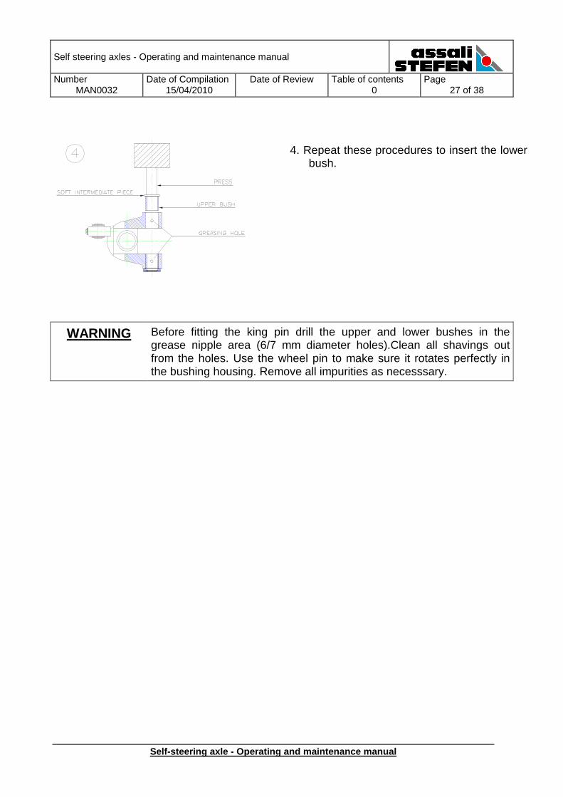
WARNING Before fitting the king pin drill the upper and lower bushes in the grease nipple area (6/7 mm diameter holes).Clean all shavings out from the holes. Use the wheel pin to make sure it rotates perfectly in the bushing housing. Remove all impurities as necesssary.
4. Repeat these procedures to insert the lower bush.
Self steering axles - Operating and maintenance manual
Number MAN0032
Date of Compilation 15/04/2010
Date of Review
Table of contents 0
Page 28 of 38
Self-steering axle - Operating and maintenance manu al
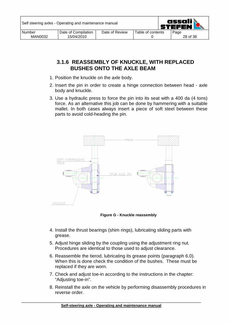
3.1.6 REASSEMBLY OF KNUCKLE, WITH REPLACED BUSHES ONTO THE AXLE BEAM
1. Position the knuckle on the axle body.
2. Insert the pin in order to create a hinge connection between head - axle body and knuckle.
3. Use a hydraulic press to force the pin into its seat with a 400 da (4 tons) force. As an alternative this job can be done by hammering with a suitable mallet. In both cases always insert a piece of soft steel between these parts to avoid cold-heading the pin.
Figure G - Knuckle reassembly
4. Install the thrust bearings (shim rings), lubricating sliding parts with grease.
5. Adjust hinge sliding by the coupling using the adjustment ring nut. Procedures are identical to those used to adjust clearance.
6. Reassemble the tierod, lubricating its grease points (paragraph 6.0). When this is done check the condition of the bushes. These must be replaced if they are worn.
7. Check and adjust toe-in according to the instructions in the chapter: “Adjusting toe-in”.
8. Reinstall the axle on the vehicle by performing disassembly procedures in reverse order.
Self steering axles - Operating and maintenance manual
Number MAN0032
Date of Compilation 15/04/2010
Date of Review
Table of contents 0
Page 29 of 38
Self-steering axle - Operating and maintenance manu al
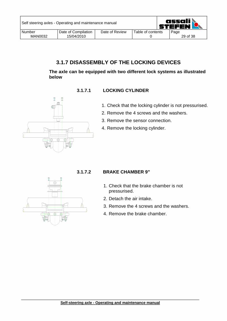
3.1.7 DISASSEMBLY OF THE LOCKING DEVICES
The axle can be equipped with two different lock sy stems as illustrated below
3.1.7.1 LOCKING CYLINDER
3.1.7.2 BRAKE CHAMBER 9”
1. Check that the locking cylinder is not pressurised.
2. Remove the 4 screws and the washers.
3. Remove the sensor connection.
4. Remove the locking cylinder.
1. Check that the brake chamber is not pressurised.
2. Detach the air intake.
3. Remove the 4 screws and the washers.
4. Remove the brake chamber.
Self steering axles - Operating and maintenance manual
Number MAN0032
Date of Compilation 15/04/2010
Date of Review
Table of contents 0
Page 30 of 38
Self-steering axle - Operating and maintenance manu al
3.1.8 REINSTALLATION OF THE LOCKING COMPONENTS
3.1.8.1 LOCKING CYLINDER
1. Place the locking cylinder on its support. Fasten it in place with the 4 screws. Tighten it with a torque of 37-40 Nm. Make sure you use new washers.
2. Connect the locking cylinder air intake.
3. Pressurize the circuit.
4. Test for proper locking.
3.1.8.2 BRAKE CHAMBER 9”
1. Place the brake chamber on its support. Fasten it in place with the 2 screws. Tighten it with a torque of 37-40 Nm. Make sure you use new washers.
2. Connect the brake chamber air intake.
3. Pressurize the circuit.
4. Test for proper locking.
Self steering axles - Operating and maintenance manual
Number MAN0032
Date of Compilation 15/04/2010
Date of Review
Table of contents 0
Page 31 of 38
Self-steering axle - Operating and maintenance manu al
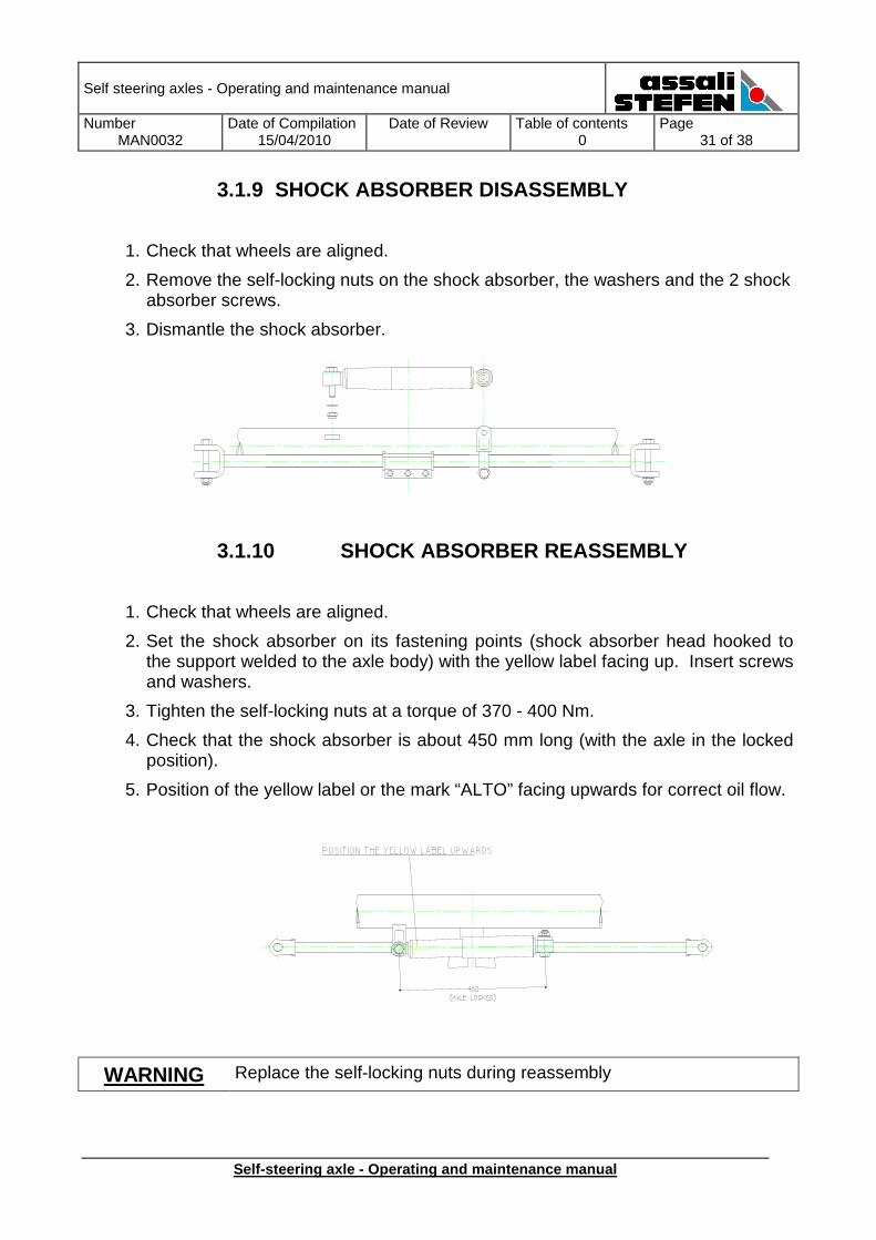
3.1.9 SHOCK ABSORBER DISASSEMBLY
1. Check that wheels are aligned.
2. Remove the self-locking nuts on the shock absorber, the washers and the 2 shock absorber screws.
3. Dismantle the shock absorber.
3.1.10 SHOCK ABSORBER REASSEMBLY
1. Check that wheels are aligned.
2. Set the shock absorber on its fastening points (shock absorber head hooked to the support welded to the axle body) with the yellow label facing up. Insert screws and washers.
3. Tighten the self-locking nuts at a torque of 370 - 400 Nm.
4. Check that the shock absorber is about 450 mm long (with the axle in the locked position).
5. Position of the yellow label or the mark “ALTO” facing upwards for correct oil flow.
WARNING Replace the self-locking nuts during reassembly
Self steering axles - Operating and maintenance manual
Number MAN0032
Date of Compilation 15/04/2010
Date of Review
Table of contents 0
Page 32 of 38
Self-steering axle - Operating and maintenance manu al
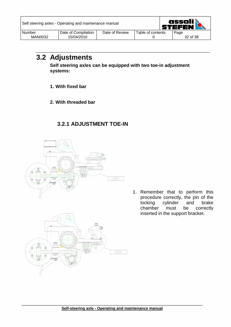
3.2 Adjustments Self steering axles can be equipped with two toe-in adjustment systems:
1. With fixed bar
2. With threaded bar
3.2.1 ADJUSTMENT TOE-IN
1. Remember that to perform this procedure correctly, the pin of the locking cylinder and brake chamber must be correctly inserted in the support bracket.
Self steering axles - Operating and maintenance manual
Number MAN0032
Date of Compilation 15/04/2010
Date of Review
Table of contents 0
Page 33 of 38
Self-steering axle - Operating and maintenance manu al
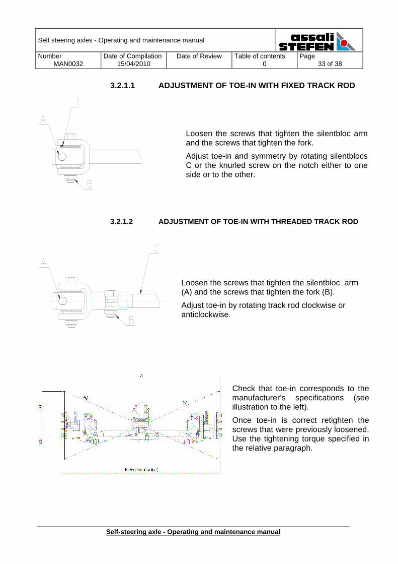
3.2.1.1 ADJUSTMENT OF TOE-IN WITH FIXED TRACK ROD
3.2.1.2 ADJUSTMENT OF TOE-IN WITH THREADED TRACK RO D
Loosen the screws that tighten the silentbloc arm and the screws that tighten the fork.
Adjust toe-in and symmetry by rotating silentblocs C or the knurled screw on the notch either to one side or to the other.
Check that toe-in corresponds to the manufacturer’s specifications (see illustration to the left).
Once toe-in is correct retighten the screws that were previously loosened. Use the tightening torque specified in the relative paragraph.
Loosen the screws that tighten the silentbloc arm (A) and the screws that tighten the fork (B).
Adjust toe-in by rotating track rod clockwise or anticlockwise.
Self steering axles - Operating and maintenance manual
Number MAN0032
Date of Compilation 15/04/2010
Date of Review
Table of contents 0
Page 34 of 38
Self-steering axle - Operating and maintenance manu al
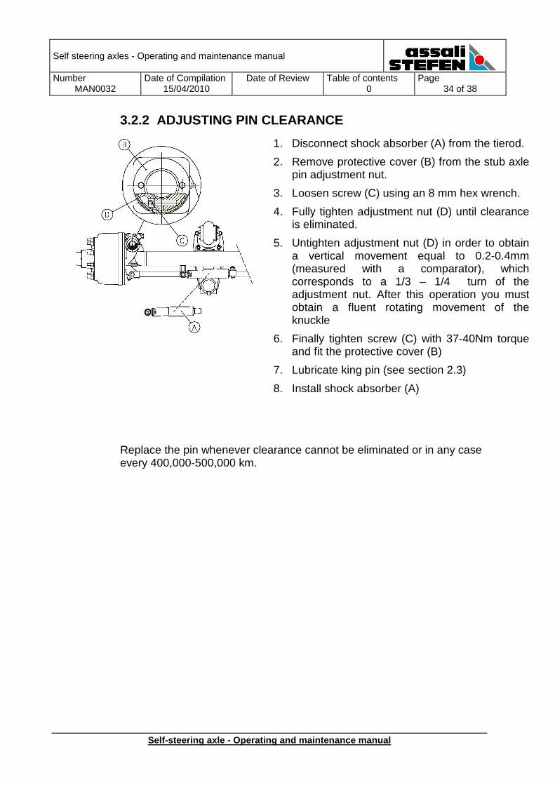
3.2.2 ADJUSTING PIN CLEARANCE
Replace the pin whenever clearance cannot be eliminated or in any case every 400,000-500,000 km.
1. Disconnect shock absorber (A) from the tierod.
2. Remove protective cover (B) from the stub axle pin adjustment nut.
3. Loosen screw (C) using an 8 mm hex wrench.
4. Fully tighten adjustment nut (D) until clearance is eliminated.
5. Untighten adjustment nut (D) in order to obtain a vertical movement equal to 0.2-0.4mm (measured with a comparator), which corresponds to a 1/3 – 1/4 turn of the adjustment nut. After this operation you must obtain a fluent rotating movement of the knuckle
6. Finally tighten screw (C) with 37-40Nm torque and fit the protective cover (B)
7. Lubricate king pin (see section 2.3)
8. Install shock absorber (A)
Self steering axles - Operating and maintenance manual
Number MAN0032
Date of Compilation 15/04/2010
Date of Review
Table of contents 0
Page 35 of 38
Self-steering axle - Operating and maintenance manu al
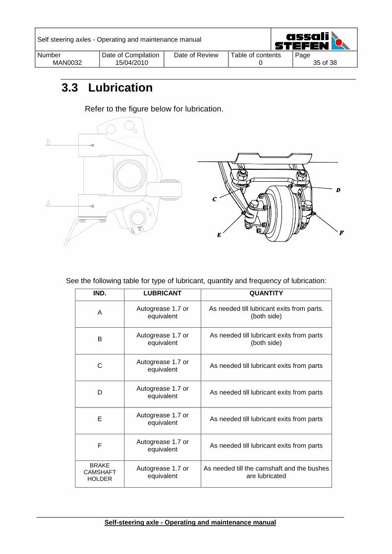
3.3 Lubrication
Refer to the figure below for lubrication.
See the following table for type of lubricant, quantity and frequency of lubrication:
IND. LUBRICANT QUANTITY
A Autogrease 1.7 or
equivalent As needed till lubricant exits from parts.
(both side)
B Autogrease 1.7 or
equivalent As needed till lubricant exits from parts
(both side)
C Autogrease 1.7 or
equivalent As needed till lubricant exits from parts
D Autogrease 1.7 or
equivalent As needed till lubricant exits from parts
E Autogrease 1.7 or
equivalent As needed till lubricant exits from parts
F Autogrease 1.7 or
equivalent As needed till lubricant exits from parts
BRAKE CAMSHAFT
HOLDER
Autogrease 1.7 or equivalent
As needed till the camshaft and the bushes are lubricated
Self steering axles - Operating and maintenance manual
Number MAN0032
Date of Compilation 15/04/2010
Date of Review
Table of contents 0
Page 36 of 38
Self-steering axle - Operating and maintenance manu al
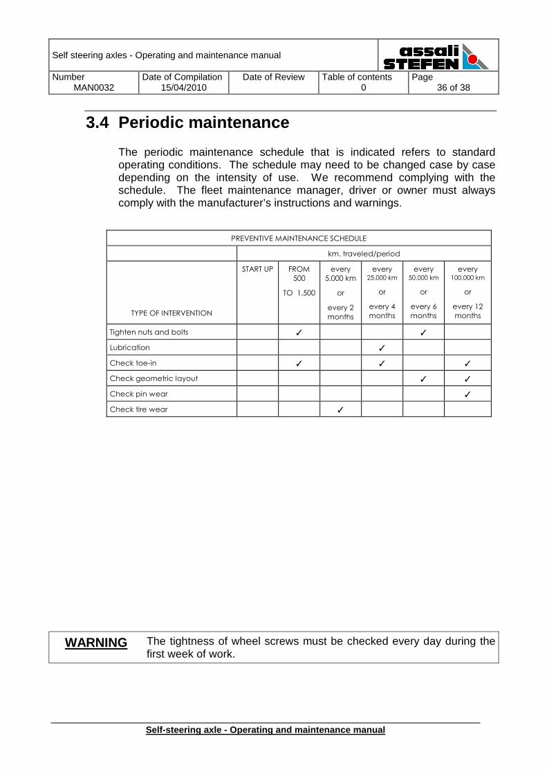
3.4 Periodic maintenance
The periodic maintenance schedule that is indicated refers to standard operating conditions. The schedule may need to be changed case by case depending on the intensity of use. We recommend complying with the schedule. The fleet maintenance manager, driver or owner must always comply with the manufacturer’s instructions and warnings.
PREVENTIVE MAINTENANCE SCHEDULE
km. traveled/period
TYPE OF INTERVENTION
START UP FROM
500
TO 1.500
every
5.000 km
or
every 2
months
every 25.000 km
or
every 4
months
every 50.000 km
or
every 6
months
every 100.000 km
or
every 12
months
Tighten nuts and bolts ✓ ✓
Lubrication ✓
Check toe-in ✓ ✓ ✓
Check geometric layout ✓ ✓
Check pin wear ✓
Check tire wear ✓
WARNING The tightness of wheel screws must be checked every day during the first week of work.
Self steering axles - Operating and maintenance manual
Number MAN0032
Date of Compilation 15/04/2010
Date of Review
Table of contents 0
Page 37 of 38
Self-steering axle - Operating and maintenance manu al
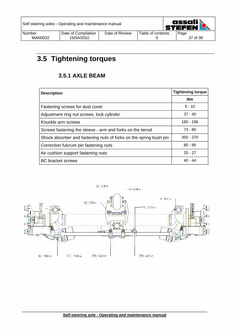
3.5 Tightening torques
3.5.1 AXLE BEAM
Description Tightening torque
Nm
Fastening screws for dust cover 9 - 10
Adjustment ring nut screws, lock cylinder 37 - 40
Knuckle arm screws 180 - 196
Screws fastening the sleeve - arm and forks on the tierod 73 - 80
Shock absorber and fastening nuts of forks on the spring bush pin 350 - 370
Correction fulcrum pin fastening nuts 85 - 90
Air cushion support fastening nuts 25 - 27
BC bracket screws 40 - 44
Self steering axles - Operating and maintenance manual
Number MAN0032
Date of Compilation 15/04/2010
Date of Review
Table of contents 0
Page 38 of 38
Self-steering axle - Operating and maintenance manu al
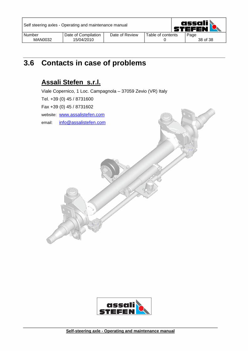
3.6 Contacts in case of problems
Assali Stefen s.r.l. Viale Copernico, 1 Loc. Campagnola – 37059 Zevio (VR) Italy
Tel. +39 (0) 45 / 8731600
Fax +39 (0) 45 / 8731602
website: www.assalistefen.com
email: [email protected]