Embed Size (px)
Citation preview

! DANGERHazardous Voltage.Will cause death or serious injury.Turn off and lock out all power before working on this equipment.
Installation
If the SEM3 equipment is used in a manner not specified by Siemens, the protection provided by the equipment may be impaired.
• During normal operation of the SEM3 meter, hazardous voltages are present on its voltage leads, and throughout the connected potential transformer (PT), digital (status) input, control power and external I/O circuits. PT circuits are capable of generating lethal voltages and currents with their primary circuit energized. Follow standard safety precautions while performing any installation or service work (i.e. removing PT fuses).
• The voltage leads to the meter should not be user‐accessible after installation.
• Do not use digital output devices for primary protection functions. These include applications where the devices
perform energy limiting functions or provide protection of people from injury. Do not use the SEM3 in situations where failure of the devices can cause injury or death, or cause sufficient energy to be released that can start a fire. The meter can be used for energy management functions.
• Do not HIPOT/Dielectric test the digital (status) inputs, digital outputs, or communications terminals. Refer to the label on the SEM3 meter for the maximum voltage level the device can withstand.
• The SEM3 metering system offers a range of hardware options that affect input ratings. Use only parts and assemblies that are made specifically for use with the SEM3 system. Failure to do so could permanently damage the meter. This document provides installation instructions applicable to each hardware option.
For more detailed installation information refer to full SEM3 Manuals available at usa.siemens.com/sem3.
Environmental ratings:
• Temperature to 14°F to 149°F (‐10°C to 65°C) • Measurement Category III (CAT III)
• Mains Supply Voltage Fluctuations up to 10% less than nominal low range the mains supply and 10% more than nominal high range of mains power supply
• CT Overvoltage Category IV (Cat IV)
Installation and maintenance of the SEM3 metering system should only be performed by qualified, competent personnel that have appropriate training and experience with high voltage and current devices. The meter must be installed in accordance with all local and national electrical codes.
SEM3™ ‐ Embedded Micro Metering Module™Quick Reference Guide and Installation Instructions
usa.siemens.com/SEM3
Scan QR Code for more information

2
Disconnecting Device:
A disconnecting device such as a switch or circuit breaker is required in case of an emergency.
• The switch or circuit breaker must be marked as the disconnecting device for the meter.
• It is recommended that the meter be mounted near the
disconnecting device in an area with adequate ventilation.
• The disconnect should not be positioned in a manner that makes it difficult to operate the disconnecting device.
To reduce risk of electric shock, always open or disconnect the circuit from the power distribution system of a building before installing or servicing current transformers.
CT Installation:
• The CTs used with the SEM3 metering system are specifically designed and rated for use with the system. Use of other CTs can be damaging to SEM3 components and cause hazardous situations. All the CTs used with this system are in compliance with the most up‐to‐date safety standards. Use only UL Listed Energy Monitor Current Transformers, evaluated and approved for SEM3 application. Size CT primary rating with the load to be measured. The CT primary rating should be equal to or greater than the load.
SEM3 Solid Core CTs 50:0.1 Solid Core CT ‐ US2:SEM3SCCT50 125:0.1 Solid Core CT ‐ US2:SEM3SCCT125 250:0.1 Solid Core CT ‐ US2:SEM3SCCT250 400:0.1 Solid Core CT ‐ US2:SEM3SCCT400 600:0.1 Solid Core CT ‐ US2:SEM3SCCT600 800:0.1 Solid Core CT ‐ US2:SEM3SCCT800 1200:0.1 Solid Core CT ‐ US2:SEM3SCCT1200
Siemens approved UL listed energy Monitoring Current Transformers other than the one listed here may also be used with the SEM3 System.
All CTs should be securly fastened within the gear such that they will not slide down to live terminals and to protect against damage.
• In accordance with NEC, CTs may not be installed in any panel board where they exceed 75% of the wiring space of any cross sectional area.
Input protection:
• The controller has five leads that are color coded and labeled to the appropriate phases and ground connection. All phase (ungrounded) connections should be protected by a 3 amp fuse or circuit breaker that is appropriate for the applied voltage and available short circuit rating. (Example: a type CC fuse rated at 3 Amp (Time‐Delay) and good for application on up to a 200 kAIC system at 480 volts).
Conductors and field wiring:
• Where applicable, “connect 14 AWG min., 600 V min. insulated wiring for Line voltages and Neutral to the appropriate location in the breaker panel, in accordance with all national and local electrical codes”.
• Connector torque rating for wiring terminals is 5 IN‐LBS
3
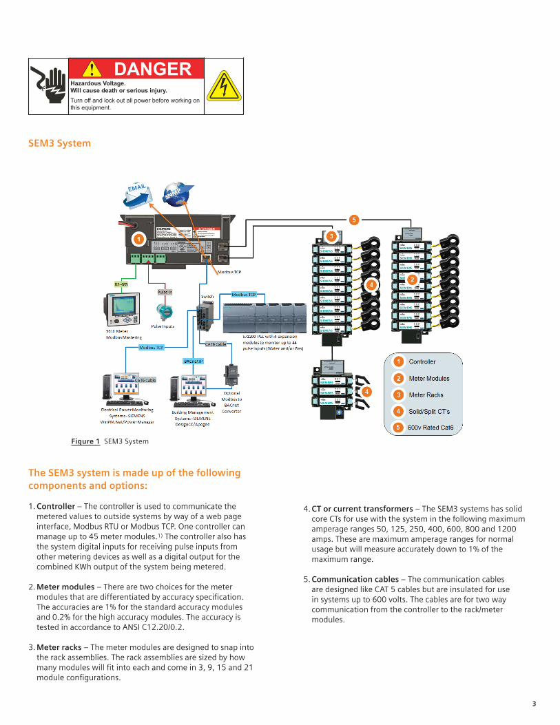
The SEM3 system is made up of the following components and options:
1. Controller – The controller is used to communicate the metered values to outside systems by way of a web page interface, Modbus RTU or Modbus TCP. One controller can manage up to 45 meter modules.1) The controller also has the system digital inputs for receiving pulse inputs from other metering devices as well as a digital output for the combined KWh output of the system being metered.
2. Meter modules – There are two choices for the meter modules that are differentiated by accuracy specification. The accuracies are 1% for the standard accuracy modules and 0.2% for the high accuracy modules. The accuracy is tested in accordance to ANSI C12.20/0.2.
3. Meter racks – The meter modules are designed to snap into the rack assemblies. The rack assemblies are sized by how many modules will fit into each and come in 3, 9, 15 and 21 module configurations.
4. CT or current transformers – The SEM3 systems has solid core CTs for use with the system in the following maximum amperage ranges 50, 125, 250, 400, 600, 800 and 1200 amps. These are maximum amperage ranges for normal usage but will measure accurately down to 1% of the maximum range.
5. Communication cables – The communication cables are designed like CAT 5 cables but are insulated for use in systems up to 600 volts. The cables are for two way communication from the controller to the rack/meter modules.
Figure 1 SEM3 System
SEM3 System
! DANGERHazardous Voltage.Will cause death or serious injury.Turn off and lock out all power before working on this equipment.

4
Configuring the system
There are a few steps in configuring the components of the SEM3 metering system. Refer to the Installation Manual instructions on mounting of the SEM3 components.
Current Transformer (CT) – There is no setting on the CT for the system. The CTs for use in the SEM3 meter system are 100 mA output and are self protecting so shorting blocks are not required. Standard CT wire length is 6 feet. CT wire length can retain accuracy up to 100 feet using 18 AWG twisted pair wire.
Meter modules – These instructions are for both levels of accuracy modules.
Each meter module is a single phase meter and must be connected to the appropriately sized SEM3 system CT. The meter modules are then snapped into place into a rack assembly. The rack assembly has the module address to the controller hard coded in the hardware.
Note: For metering of multi‐pole circuit breakers, the meter modules must be mounted contiguously to each other.
Gaps in the rack will not allow multi‐pole meters to be configured. Each module must have the phase dip switch on the top of the module set to the phase that the CT is metering; phase A, B, or C (Line 1, 2, or 3 respectively).
Note: Once the meter module is placed into the rack and energized the phase position will be indicated by a different color LED for each position. These descriptions are for the connections to the controller not the LED colors on the meter module. (L1 phase A color is orange; L2 color is yellow; L3 color is green.) The LEDs are adjacent to the phase numbers. The Kwh pulse is available for an accuracy check as stipulated by some authorities KT=10 (5 on ‐5 off). CT sizing for each meter module will be done through the controller web page later in configuration.
Controller – The controller functions as the set up interface for the system. System settings, CT ratios, PT ratios, alarm settings, communications settings and passwords are all set using the web page interface of the controller. See Installation Manual instructions for mounting and dimensional information.
To start – Connect the controller to a PC using the Ethernet / Modbus TCP port. See Figure 4.
Assign Static IP addressTo change the PC / computer’s IP address in Windows 7 / 8, 1. Type network and sharing into the Search box in the Start Menu and select
Network and Sharing Center when it comes up.2. Then when the Network and Sharing Center opens, click on Change adapter
settings.3. Right‐click on your local adapter and select Properties.4. In the Local Area Connection Properties window highlight Internet Protocol
Version 4 (TCP/IPv4) then click the Properties button.5. Select the radio button and enter the correct IP address Ex. 192.168.1.100,
and Subnet mask 255.255.0.0. The PC static IP address should be in the same IP address range of the SEM3 controller.
6. Close out of the Local Area Connections Properties window.7. You can open the command prompt and do an ipconfig to see the network
adapter settings have been successfully changed.
Ping your SEM3 Controller (Default IP address: 192.168.1.65)Open a Command Prompt and at the prompt type “ping” followed by a space & the IP Address of your SEM3 and press Enter.
You should get the following:Pinging 192.168.1.65 with 32 bytes of data:
Reply from 192.168.1.65: bytes=32 time=56ms TTL=250Reply from 192.168.1.65: bytes=32 time=60ms TTL=250Reply from 192.168.1.65: bytes=32 time=69ms TTL=250Reply from 192.168.1.65: bytes=32 time=78ms TTL=250
LED indicates Phase position switch location
CT wire screw terminals
CT wire terminal blocks
Solid core shown, split core available
Three phase wiring
Isolated RS485C
Two energy pulse in
Energy pulse out
Left rail
MODBUS TCP/IP
Right rail
Figure 2 Current transformer
Figure 3 Meter module
Figure 4 Controller
(continued on next page)
Release lever to allow easy removal from the rack
KWH pulse
Blue mark indicates high accuracy, and burgundy mark indicates standard accuracy
QR code
5
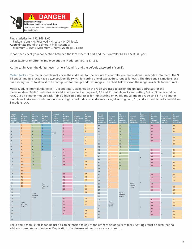
The 3 and 6 module racks can be used as an extension to any of the other racks or pairs of racks. Settings must be such that no address is used more than once. Duplication of addresses will return an error on setup.
Meter Module Internal Addresses – Dip and rotary switches on the racks are used to assign the unique addresses for themeter module. Table 1 indicates rack addresses for Left setting on 9, 15 and 21 module racks and setting 0‐7 on 3 meter module rack, 0‐3 on 6 meter module rack. Table 2 indicates addresses for right setting on 9, 15, and 21 module racks and 8‐F on 3 meter module rack, 4‐7 on 6 meter module rack. Right chart indicates addresses for right setting on 9, 15, and 21 module racks and 8‐F on 3 module rack.
Meter Racks – The meter module racks have the addresses for the module to controller communications hard coded into them. The 9, 15 and 21 module racks have a two position dip switch for setting one of two address ranges for each. The three and six module rack has a rotary switch to allow it to be configured for multiple address ranges. The chart below shows the ranges available for each rack.
Ping statistics for 192.168.1.65: Packets: Sent = 4, Received = 4, Lost = 0 (0% loss),Approximate round trip times in milli‐seconds: Minimum = 56ms, Maximum = 78ms, Average = 65ms
If not, then check your connection between the PC’s Ethernet port and the Controller MODBUS TCP/IP port.
Open Explorer or Chrome and type out the IP address 192.168.1.65.
At the Login Page, the default user name is “admin”, and the default password is “sem3”.
! DANGERHazardous Voltage.Will cause death or serious injury.Turn off and lock out all power before working on this equipment.
Single Phase Monitor Modbus Addresses
21 Position Rack Modbus Addresses
15 Position Rack Modbus Addresses
9 Position Rack Modbus Addresses
6 Position Rack Rotary Switch Setting�
6 Position Rack Modbus Addresses
3 Position Rack Rotary Switch Setting
3 Position Rack Modbus Addresses
1 1 1 1
0 (8)
1
0
1
2 2 2 2 2 2
3 3 3 3 3 3
4 4 4 4 4
5 5 5 5 5
1
5
6 6 6 6 6 6
7 7 7 7 7
8 8 8 8
9 9 9 9
1 (9)
9
2
9
10 10 10
Open Address Space
10 10
11 11 11 11 11
12 12 12 12
13 13 13 13
3
13
14 14 14 14 14
15 15 15 15
16 16
Open Address space
17 17
2
17
4
17
18 18 18 18
19 19 19 19
20 20 20
21 21 21
5
21
22
Open Address Space
22 22
23 23
24
25
3
25
6
25
26 26 26
27 27 27
28 28
29 29
7
29
30 30 30
31 31
32
Single Phase Monitor Modbus Addresses
21 Position Rack Modbus Addresses
15 Position Rack Modbus Addresses
9 Position Rack Modbus Addresses
6 Position Rack Rotary Switch Setting
6 Position Rack Modbus Addresses
3 Position Rack Rotary Switch Setting
3 Position Rack Modbus Addresses
33 33 33 33
4
33
8
33
34 34 34 34 34 34
35 35 35 35 35 35
36 36 36 36 36
37 37 37 37 37
9
37
38 38 38 38 38 38
39 39 39 39 39
40 40 40 40
41 41 41 41
5
41
A
41
42 42 42
Open Address Space
42 42
43 43 43 43 43
44 44 44 44
45 45 45 45
B
45
46 46 46 46 46
47 47 47 47
48 48
Open Address space
49 49
6
49
C
49
50 50 50 50
51 51 51 51
52 52 52
53 53 53
D
53
54
Open Address Space
54 54
55 55
56
57
7
57
E
57
58 58 58
59 59 59
60 60
61 61
F
61
62 62 62
63 63

6
Login page – Default user name is “admin”, Default password is “sem3”. User name and password can be set to user preference and are case sensitive. See the User Manual for more detail.
The web page has other settings available and can be accessed by clicking on the tabs at the top of the page.
System settings – The following may be set from this page: (See user manual for more information)• IP configuration – For configuration of the IP address if using
Modbus TCP. Be sure to write down the new IP address as you will lose communications once saved.
• RTU slave configuration – For setting of address if used as a Modbus RTU device
• Real time refresh interval – Time interval for the web page to refresh real time date
• Device description – For naming of the system• Panel configurations to include: • Demand sub interval – Number of measurements taken
in the sub interval • Sub interval length – Time between intervals • Voltage mode – Delta or Wye • Line to Neutral / Line to Line voltage depending on
voltage mode • Potential Transformer (PT) Primary voltage – Secondary
preset to 120Save – Data changes must be saved before leaving this page or it will be lost. Reset
Data available from this page –• Firmware version • Serial number of the controller
Global settings – Global settings will be applied across all the meters in the system. Each meter can be customized in the Branch meter configuration screen. The alarms are for the meters and not meter modules. Individual phase alarms can only be set for single pole meters. Alarm delays are time settings where the meter is in alarm condition before the alarm flag is set. This is to prevent momentary conditions sending alarm flags.
Multi-pole circuit breaker configuration – This page is used to configure the meter modules into meters. The bottom of the page displays those meters configured from the bottom of the page. The meter configuration is drag and drop from the available module column to the different meter configurations (1, 2 or 3 pole). Note that modules have to be mounted contiguously in the racks to be configured as multi‐pole meters.
Branch meter configuration – This page allows for customization of the configured meters. Custom alarms may be set that override the global alarms as well as naming of the individual meters.
Real time data – This screen gives an overview of the alarm status of the configured meters and allows for clearing of the individual meter alarms. Clicking on the individual meters will display that meters real time information to the right of the grid.
User profile – This page is accessible to all users who can modify their details except the ‘User ID’ and ‘Access Level’. User ID and Access Level are set by the Supervisor only from the User management screen.
User management – This page is accessible to ‘Supervisor’ user who can manage users’ accounts that includes adding, removing and modifying the users. There are three levels of users available:
• Supervisor – Has the ability to see all data and modify setting and clear alarms and add or modify user settings.
• Controller – Has the ability to see all data and to clear alarms. Controller cannot see or modify user management.
• Observer – Has the ability to see data but is not allowed to modify or clear alarms.
Diagnostics – This page is accessible to ‘Supervisor’ user.The SEM3 metering system can work with supervisory systems such as WinPM.Net, Power manager and other SCADA or Building management systems that use Modbus protocol. The Modbus registers for this product are such that configuration using the controller web interface is not absolutely necessary, but by doing so valuable time can be saved.
1) Some applications will allow for more than 45 poles in one enclosure by adding a second controller. Two controllers can monitor up to 90 poles.

7
Notes

Siemens Industry, Inc.5400 Triangle Parkway Norcross, GA 30092
1‐800‐241‐4453 [email protected]
Order No. RPFL‐SEM3Q‐0916 Ref. No. 814388 Rev. 3P Printing in USA © 2016 Siemens Industry, Inc.
Subject to changes and errors. The information given in this document only contains general descriptions and/or performance features which may not always specifically reflect those described, or which may undergo modification in the course of further development of the products. The requested performance features are binding only when they are expressly agreed upon in the concluded contract.