Embed Size (px)
Citation preview

Drilling, Reservoir & Well Engineering
Study
Authors: Supervisor:
Nikolaos G. Felessakis (8653) Dr E. Dimou
Date: 24/12/2013
2
Table of Contents
QUESTIONS 3
QUESTION 1: 3
WHAT TYPE OF DRILLING RIG YOU ARE GOING TO SELECT AND WHY? 3
WHAT IS THE PROCESS FOR DRILLING (BRIEF DESCRIPTION) FOR A DRY HOLE COMPLETION? 3
WHAT ARE THE MAIN WELL CONTROLS FOR PREVENTING ACCIDENTS FROM ABNORMAL WELL CONDITIONS AND
HOW THEY WORK? 5
YOU NEED TO SUBMIT A DRILLING PLAN. WHAT FACTORS YOU NEED TO CONSIDER IN ORDER TO PROVIDE A SAFE
DRILLING ACTIVITY TO THE RIGHT PLACE? 6
QUESTION 2: 9
A. THE COSTS SUBMITTED FROM THE DRILLING CONTRACTOR ARE SUFFICIENT TO ENABLE THE COMPANY TO APPLY
FOR THE THREE LICENSES 9
B. IN THE CASE THAT THE COST IS NEAR TO THE MARKET CAP VALUE OR EXCEED IT, PLEASE PROPOSE WAYS THAT
THE COST COULD BE REDUCED CONSIDERING DATA GIVEN IN KELLS ENVIRONMENTAL STATEMENT REPORT. 10
C. DEFINE THE MAIN PARAMETERS THAT MADE THE COST REDUCED AND EXPLAIN YOUR APPROACH. 11
D. BASED ON YOUR PROPOSED APPROACH, IS IT POSSIBLE FOR THE COMPANY TO APPLY FOR THE LICENSING
ROUND BASED ON THE NEW DATA?(THE DATA PROVIDED FOR YOUR CALCULATIONS ARE THE QUOTES FROM THE
DRILLING COMPANY SHOWN IN APPENDIX1.) 13
QUESTION 3 13
AT WHAT POINT IN TIME WOULD YOU HAVE SUGGESTED THAT THE BIT BE PULLED AND WHY? 13
QUESTION 4 16
4A. PLOT THE FOLLOWING PORE PRESSURE/DEPTH INFORMATION ON A PRESSURE - DEPTH DIAGRAM (PRESSURE X
AXIS, DEPTH AT Y AXIS) 16
4B. CALCULATE THE PORE PRESSURE GRADIENTS IN THE FORMATIONS FROM SURFACE TO: 16
4D. IF THE MUD WEIGHT USED TO DRILL DOWN TO 8000FT WERE USED TO DRILL INTO THE FORMATION PRESSURES
AT 8500FT WHAT WOULD BE THE OVER/UNDERBALANCE ON THE FORMATION PORE PRESSURE AT THIS DEPTH? 18

Drilling, Reservoir and Well Engineering
_____________________________________________________________________________________________________
3
Questions
Question 1:
You are assigned to describe the process for selecting a drilling unit for drilling a well
in a water depth of 100m.
What type of drilling rig you are going to select and why?
The only information for this drilling well is the water depth at 100m with this
parameter the economic options is the Jack-up rig that is able to operate until150m
depth and an average rent cost per day is close to 90.000$1
What is the process for drilling (brief description) for a dry hole
completion?
The last step of hydrocarbons exploration is to drill in the point that we expect
hydrocarbons existence. A Part of this procedure includes the drilling process and
the first steps staring with the specific part of the well casing. The casing is the main
part of the well construction, and is needed to2 :
• Maintain borehole stability,
• Prevent contamination of water sands,
• Isolate water from producing formations,
• Control well pressures during drilling, production, and work over operations,
• To provides space for the farther installations.
The casing has six basic levels :
• Conductor Casing
Is the first string set below the structural casing. Under the surface hole is
cemented in place along its full length to ground surface. A diverter or
blowout prevention (BOP) is installed in this point. The main purposes are to
prevent all the unconsolidated surface sediments and to isolate shallow
groundwater from the contents of the hole.
• Surface Casing
1 http://www.rigzone.com/data/dayrates/ 2 http://petrowiki.spe.org/Casing_and_tubing

4
The main purpose of surface casing is for well control, and to provide blowout
protection, isolate water sands, and prevent lost circulation. It also provides
the support point to drill into high-pressure transition zones.
• Intermediate Casing
The purpose of intermediate casing is to isolate any abnormally-pressured
subsurface rock formations from causing instability. If the exploratory drilling at
this point has discovered profitable quantities of hydrocarbons, a wellhead3
valve assembly will be installed. If the well does not contain commercial
quantities of hydrocarbon the site is decommissioned to a safe and stable
condition and restored to its original state.
• Production Casing
The primary purpose of production casing is to isolate the zone containing
natural gas from other subsurface formations. It’s also used to pump hydraulic
fracturing fluids into the producing formation without contacting other
formations along the wellbore.
• Liner
Liners are used instead of full casing strings to:
o Reduce the cost
o Improve hydraulic performance when drilling deeper and
o Allow the use of larger tubing above the liner top
Liners can be either an intermediate or a production string.
In this case the well is considered as a “dry hole”. As a dry hole well probably does
not contain commercial quantities of Oil or Gas to move for production, or with the
existence technology to be unable the exploitation. The next step is to plugged and
abandoned the well.
The propose of plugged4 is to:
o Prevent the mixing of fluids from different geologic levels,
o Prevent the flow of fluids from pressurized zone to the surface, and
o Maintain pressure integrity in the individual subsurface intervals.
3 http://www.dmitre.sa.gov.au/invest_in_south_australia/major_developments_directory/case_studies/santos 4 http://www.dec.ny.gov/docs/materials_minerals_pdf/dgeisv1ch11.pdf

Drilling, Reservoir and Well Engineering
_____________________________________________________________________________________________________
5
All the above steps are following the Plugging regulations
What are the main well controls for preventing accidents from abnormal
well conditions and how they work?
Well control is about keeping formation fluids in the formation and drilling fluids out
of the formation any undesirable flow of formation fluids into the wellbore is called
the kick. The kick has to controlled properly otherwise it can grow rapidly and cause
a blowout. A blowout is an uncontrolled flow of formation fluids into the wellbore,
with catastrophic results.
To keep the well control there are:
o Primary control system,
o Secondary control system.
The primary control is related with the drilling mud and the pressure. The main
purpose is hydrostatic pressure to balance formation pressure. The mechanism to
keep the balanced drilling is the mud characteristics as the :
o Weight or Density,
o Viscosity,
o pH.
When the formation pressure is bigger than the hydrostatic pressure then the
reservoir fluids entering in the wellbore. This situation is been reverse by increasing
the weight of the mud, and that can be achieved by adding barite or calcium
carbonate. If the Hydrostatic pressure was bigger than formation pressure the drilling
fluids being lost to the formation. To restore the balance between FP and HP it can
be achieved by decreasing the weight of the mud. The prices of Viscosity can be
controlled by adding behtonite. The pH has to be alkaline close to 9pH if its less it
can be increased by adding caustic soda.
The secondary control is been provided from a valve system that stop the fluid flow
from the well and gives time to recover the stable well conditions. This system
include the:

6
o Blowout Preventer Stack (BOP)and is installed on the top of the casing,
o Rig choke on the platform.
The blowout preventer also contains a series of annular preventers, and Ram’s
stacked on top of one another. For this reason the blowup preventer is sometimes
called a BOP stack the annual preventer’s and rams and the BOP stack all have
one thing in common, when closed they sealed off the space inside the BOP, in
order to isolate the well below, or to contain pressure inside the well. An Annular
preventer is a large rubber element shaped like a doughnut when activated the
annular preventer expense inward, if the space is empty the annular preventer seals
the open hold entirely, if there is drill pipe in the space the annular preventer seals
around the pipe. The blowout preventer also contains variable board rams also
called pipe rams. Pipe rams are made of metal and elastomer’s, when activated
the two sides of the pipe ram slide into place around the drill pipe, sealing off the
drill and the wellbore space (also known as annual space), pipe rams generally
have higher pressure ratings than annular preventers. The blind shear ram consist of
two middle blocks with blades on the inside edges, when activated the two have
slight together to seal off the space inside the BOP shutting in the well entirely. In an
emergency the relationship through drill pipe that is inside the BOP though they
cannot share through the thick tool joints were sections of drill pipe or screwed
together. All the elements of the BOP stacker designed to shut in well and contain
pressure inside the wellbore.
Choke system keeping the pressure on bottom whole constant. It’s a system with
several safety valves. By adjusting the openings of the choke making the opener
larger or smaller. The smaller the opening the less flow, the larger the opening the
more flow. The less flow creates more backpressure on the well and vice versa.
You need to submit a drilling plan. What factors you need to consider in
order to provide a safe drilling activity to the right place?
The drilling plan is formulated from many variables, for this reason its mandatory to
follow a basic's principals aspects as the safety, minimum cost, and operability. Its

Drilling, Reservoir and Well Engineering
_____________________________________________________________________________________________________
7
planning parameter giving as the important details to forward in the next one as
been described in the next Hierarchy table
8
Drilling Depth
Location
The location ditermine the specific regulations tha has to follow
Well Casing
Total casing depth
Fracture pressure
Type of Drilling Rig
Cement Storage Unti BOP
Evry drilling has unique
specifications
Power Generatores Pumps
Formation Presures
The formation pressure it will deermine the type and the
cuantites of chemical tha are nesseserey to keep the balance bitween the Formation pressure
and the Mud pressure
Environmental Assesment
Drilling Procces
Production Facillity Rig Selection
Weather Conditions

Drilling, Reservoir and Well Engineering
_____________________________________________________________________________________________________
9
Question 2:
A company wants to become an operator in UKCS and they want to apply for
three licenses. The conditions for the licenses are that the operator – as a company-
has to have a market cap that it is sufficient to cover the expenses of the proposed
drilling program. The government sets up the following criteria for the financial
eligibility:
Market cap should be sufficient to cover:
a. 100% of the most expensive well,
b. 50% of the cost of the other wells.
Due to the fact that the company wants to apply for three licenses, which means to
drill 3 wells, they contacted a drilling contractor to estimate the cost for a dry hole
drilling. The drilling contractors submitted the figures shown to Appendix to the
company.
The company had to review the figures and make comments on them since the
Market Cap is 25 MM pounds.
Please determine if:
a. The costs submitted from the drilling contractor are sufficient to
enable the company to apply for the three licenses
The company Market Cap Wells
Market
cap per
Well to
cover
Total Dry hole Cost
The licenses
cost by
following the
government
criteria
£ 25,000,000
A 100% £27,450,000 £27,450,000
B 50% £10,000,000 £5,000,000
C 50% £11,100,000 £5,550,000
Total Dry Hole Cost for the three Licenses £38,000,000

10
As we can see from the table, the company market cap is £13,000,000 £ less from
the costs submitted from the drilling contractor. With this cost the company is not
able to apply for the Licenses.
b. In the case that the cost is near to the market cap value or exceed it,
please propose ways that the cost could be reduced considering data
given in Kells environmental statement report.
The common characteristics of this case with Kells is that the wells are exist in the
same area. This area has a specific depth of 91.44m that give as the option to
change the Rig from Semi – Submersible to Jack up that has significant economical
day rate and to ask the driller to provide as an other offer with Jack up rig.
Also the budgetary cost estimates are calculated with estimations and not a
turnkey contract. So we can assume that the drilling days per drilling depth are also
estimations. Compering the drilling data of Contractor for each well, with the drilling
data of Kells that is a field close to our location. That give as the benefit of the similar
geological structure. As we can see from the next table at kells Well deeper drill
hole has been done in less days. So we can ask from the contractor a better
estimation.
Hole
section 36' 26' 17' 12' 8'
Wells
Data
D*
*
Depth
(ft)
D*
*
Depth
(ft)
D*
*
Depth
(ft)
D*
*
Depth
(ft)
D*
*
Depth
(ft)
Kells 2.5 784 9.5 3,317 9 7,992 10 13,917 3 15,055
A well 3 620 8.75 3,000 11.8 8,500 21.5 13,200 4.5 13,800
B well 3.25 620 7.25 2500 3 6080
C well 3.25 620 7.25 2500 5.5 8280
Table 1 Wells comparison Days and Depth
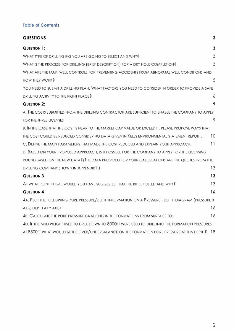
Specially we can see on the next diagram between Kells well and the A well from
contractor That in kells from 8000 ft to 13.900 ft it needs close to 4 days and our
contractor needs 16 days for less distance.

Drilling, Reservoir and Well Engineering
_____________________________________________________________________________________________________
11
Table 2 Comparison day rate per drilling depth between Kells Well with A well from Contractor
c. Define the main parameters that made the cost reduced and explain
your approach.
As I mention above the main parameters are :
o To change the Rig type, and
o The Contract type
The Semi Submersible day rate is 200.000 £ the average day rate cost for the
available5 Jack up’s is close to 59.455 £. The new total dry hole drilling cost per well is
calculated in the next Table 3
Rig Rate /day Wells Total Days Jack up Cost New
Budgetary Rate
£59,455 A 49.5 £2,943,023 £15,943,023
£59,455 B 13.6 £808,588 £4,438,588
£59,455 C 16.0 £951,280 £5,251,280
Table 3 Total Jack Up cost per Well
With the above Drilling cost the Licenses criteria are demonstrates according the
next Table 4.
5 http://www.rigzone.com/data/dayrates/
784
3,317
7,992
13,917
15,055
620
3,000
8,500
13,200 13,800
-‐
2,000
4,000
6,000
8,000
10,000
12,000
14,000
16,000
0 2 4 6 8 10 12 14 16 18
"Kells Data"
"Contractor Data A well"

12
Market Cap Wells
Market cap
per Well to
cover
Total Dry hole Cost
The licenses cost
by following the
government
criteria
£ 25,000,000
A 100% £15,943,023 £15,943,023
B 50% £4,438,588 £2,219,294
C 50% £5,251,280 £2,625,640
Total Dry Hole Cost for the three Licenses £20,787,957
Table 4 Total Dry Hole Cost for the three Licenses
With the Jack Up rig the TD Hole Cost for the three Licenses is £20,787,957 that is
£9,037,044 less than the previous TD Hole Cost with Semi Sub. With this new TD Hole
Cost The Company is able to cover the criteria for financial eligibility.
Additionally about the drilling depth and the days as we can see from the table 1
Well Depth (ft) Total Days
Kells 15055 33.5
A well 13800 49.5
B well 6080 13.5
C well 8280 16
We can ask to reduce the days based on kells data and an approach of this can
be :
o For the A Well to be reduced about 18 days,
o for the B Well 4.5 days and
o for the C well 3.5
That means a total reduce of 26 days
In order to convince the contractor to accept all the above cost reduce we can
propose an Incentive contract and gain from the historical data cost from the Kells
and The contractor will be entirely in charge of drilling for the well’s. By that we
avoid the bud behavior to make the hole quickly. Also from the cost savings that
has been achieved we can set bonus for better performance or in the worst
scenario to be split between company and contractor

Drilling, Reservoir and Well Engineering
_____________________________________________________________________________________________________
13
c. Based on your proposed approach, is it possible for the company
to apply for the licensing round based on the new data?
(The data provided for your calculations are the quotes from the drilling company shown in
Appendix1.)
With the above proposes the company is able to apply for the license round
because it covers the financial criteria.
Additionally can further reduce the cost close to £1,545,830 more by reducing the
total drilling days. An approximation of total saving can achieved to £10,582,874
Question 3
Whilst drilling a 12 1/4" hole section of the new well the following drilling data is being
recorded and provided to the company man.
At what point in time would you have suggested that the bit be pulled
and why?
Assume an average trip time of 8h, a rig rate of £400/h and the bit type
selected above had been run in hole. Decision based on the cost of the bit.
Data
Rig Rate ($) 400
Bit Cost ($) 1600
Trip Time (h) 8
The total cost of run function is :
o Bit cost + Rig Rate x (trip time +time on bottom)
The cost per foot function is :
o Total cost of run / footage drilled

14
Drilling time (h) Footage Drilled (ft) Total Cost of Run Cost per foot ($/ft)
1 34 5200 153
2 62 5600 90
3 86 6000 70
4 110 6400 58
5 126 6800 54
6 154 7200 47
7 180 7600 42
8 210 8000 38
9 216 8400 39
10 226 8800 39
11 234 9200 39
12 240 9600 40
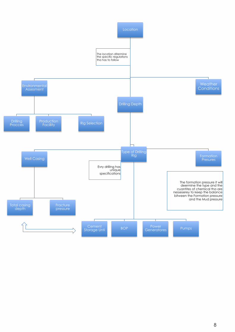
Consider all the available data, and specially the bit performance over the time I
will suggest the company man to pull the bit out at 8 hours. The decision taken
based on two parameters :
o The cost per foot
o The drilled time per foot
0 20 40 60 80
100 120 140 160 180
0 2 4 6 8 10 12 14
Bit run Cost

Drilling, Reservoir and Well Engineering
_____________________________________________________________________________________________________
15
As we can see in the table and also in the diagram after the 8h its no longer
economical to drill. That because the drilled time per foot decreases and the cost
per foot begin to increases, so it will be economical to pull the bit.
It should be noted that the bit had not entered in a new formation type, since this
may affect on the bit performance.
16
Question 4
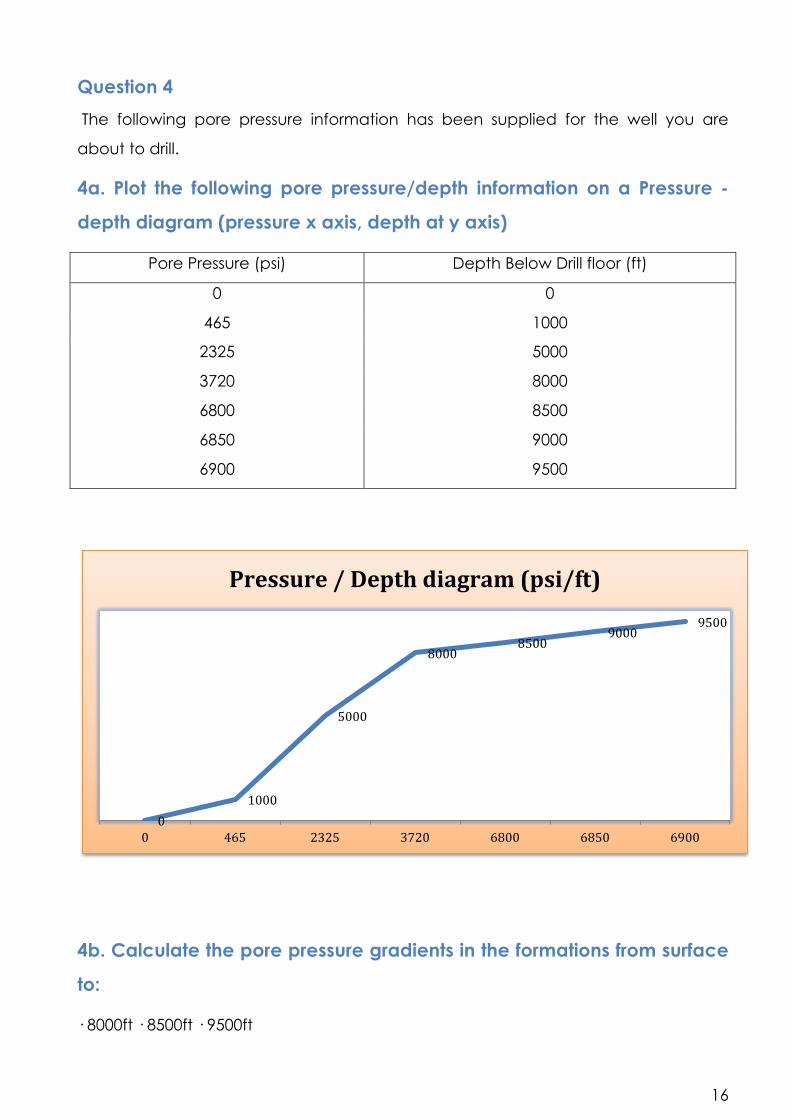
The following pore pressure information has been supplied for the well you are
about to drill.
4a. Plot the following pore pressure/depth information on a Pressure -
depth diagram (pressure x axis, depth at y axis)
Pore Pressure (psi) Depth Below Drill floor (ft)
0 0
465 1000
2325 5000
3720 8000
6800 8500
6850 9000
6900 9500
4b. Calculate the pore pressure gradients in the formations from surface
to:
· 8000ft · 8500ft · 9500ft
0 1000
5000
8000 8500
9000 9500
0 465 2325 3720 6800 6850 6900
Pressure / Depth diagram (psi/ft)
Drilling, Reservoir and Well Engineering
_____________________________________________________________________________________________________
17
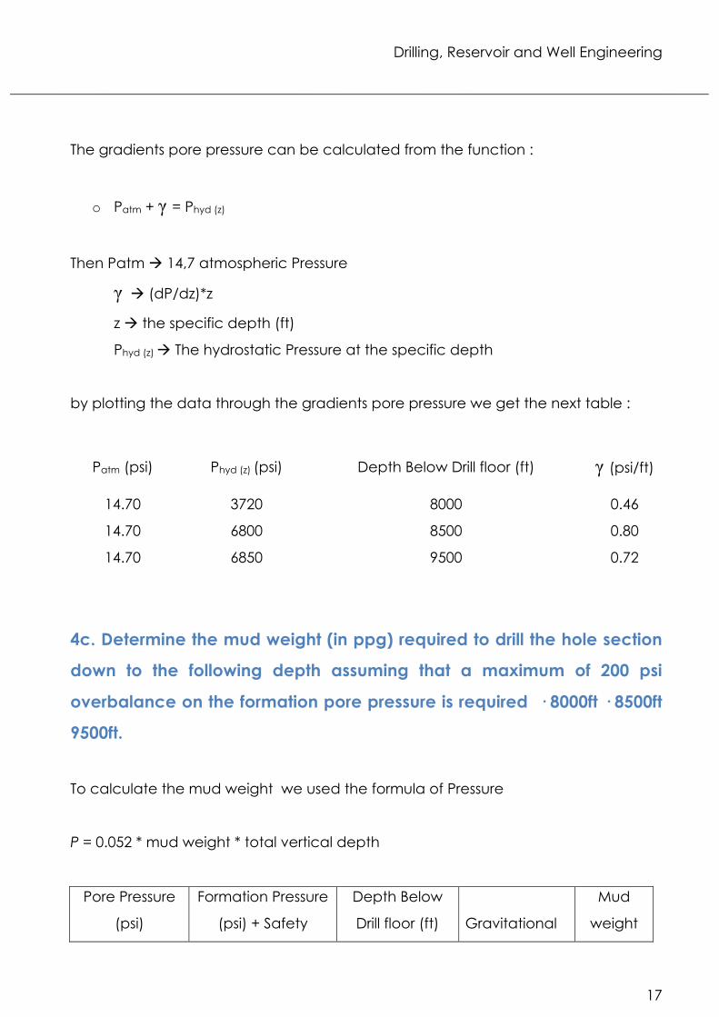
The gradients pore pressure can be calculated from the function :
o Patm + γ = Phyd (z)
Then Patm à 14,7 atmospheric Pressure
γ à (dP/dz)*z
z à the specific depth (ft)
Phyd (z) à The hydrostatic Pressure at the specific depth
by plotting the data through the gradients pore pressure we get the next table :
Patm (psi) Phyd (z) (psi) Depth Below Drill floor (ft) γ (psi/ft)
14.70 3720 8000 0.46
14.70 6800 8500 0.80
14.70 6850 9500 0.72
4c. Determine the mud weight (in ppg) required to drill the hole section
down to the following depth assuming that a maximum of 200 psi
overbalance on the formation pore pressure is required · 8000ft · 8500ft
9500ft.
To calculate the mud weight we used the formula of Pressure
P = 0.052 * mud weight * total vertical depth
Pore Pressure
(psi)
Formation Pressure
(psi) + Safety
Depth Below
Drill floor (ft)
Gravitational
Mud
weight

18
Pressure Required acceleration
(ppg)
3720 3920 8000
0.052
9.42
6800 7000 8500 15.84
6900 7100 9500 14.37
4d. If the mud weight used to drill down to 8000ft were used to drill into
the formation pressures at 8500ft what would be the over/underbalance
on the formation pore pressure at this depth?
Using the mud weight at 8000ft to 8500ft the Mud pressure is 4.165(psi)
The Deferens between Pore pressure and the specific mud pressure at 8500ft is
-2.635 (psi)
So its obvious that it will be Underbalance and it will create a Kick.