Embed Size (px)
Citation preview
BULETINUL INSTITUTULUI POLITEHNIC DIN IAŞI Publicat de
Universitatea Tehnică „Gheorghe Asachi” din Iaşi Tomul LXI (LXV), Fasc. 4, 2015
Secţia CONSTRUCŢII. ARHITECTURĂ
SEMI-RIGID BEHAVIOUR OF BOLTED CONNECTIONS USING
ANGLE CLEATS PART 1. DEVELOPMENT OF 3-D FINITE ELEMENT MODEL
BY
MARCEL GHINDEA*, ALEXANDRU CĂTĂRIG and
ROBERT-ISTVAN BALLOK
Technical University of Cluj-Napoca,
Faculty of Civil Engineering
Received: October 14, 2015 Accepted for publication: October 30, 2015
Abstract. This paper presents the design process and the results obtained
by numerical simulation for a set of beam-column bolted joint using angle cleat elements. The finite element modelling is performed using Abaqus software based on experimental results completed recently. Four different beam-to-column angle cleat connections were considered as in the experimental program. This paper presents numerical models and their results for four beam-column bolted joints using the angle cleat arranged lower, upper and on the web of the element. The aim of this paper is to develop a numerical model calibrated based on laboratory results obtained by other researchers, which further can be studied independent of experimental data, respectively to use this model for performing the parametric studies in order to achieve results and conclusions with high degree of interest in the study of semi-rigid joints behaviour.
Key words: finite element analysis; beam-to-column joints; semi-rigid joints; angle cleat; Abaqus.
1. Introduction
Analysis of framed steel structures is carried out traditionally by considering beam-to-column joints either rigid or pinned. Although advanced *Corresponding author: e-mail: [email protected]
54 Marcel Ghindea, Alexandru Cătărig and Robert-Istvan Ballok
methods have been proposed for calculating framed structures that take into consideration the semi-rigidity of the joint, their performance depends on adequate modelling and assessment of the connection (Onimus et al., 2009). In reality beam-to-column connections possess some stiffness, which falls between the two extremes rigid or pinned, resulting semi-rigid joints with nonlinear behaviour. The advantages of considering the semi-rigidity connections are economic and structural.
Although the research work concerning semi-rigid connection behaviour are extensively documented, they are not fully covered with appropriate design method for the practical design (Timoshenko & Goodier, 1951; Kurino & Kobori, 1999). In this article an advanced finite element method approach using commercial FEM software Abaqus is developed.
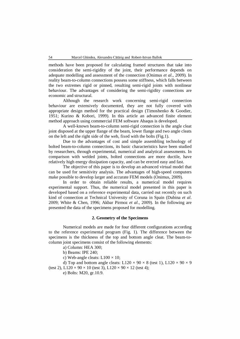
A well-known beam-to-column semi-rigid connection is the angle cleat joint disposed at the upper flange of the beam, lower flange and two angle cleats on the left and the right side of the web, fixed with the bolts (Fig.1).
Due to the advantages of cost and simple assembling technology of bolted beam-to-column connections, its basic characteristics have been studied by researchers, through experimental, numerical and analytical assessments. In comparison with welded joints, bolted connections are more ductile, have relatively high energy dissipation capacity, and can be erected easy and fast.
The objective of this paper is to develop an advanced virtual model that can be used for sensitivity analysis. The advantages of high-speed computers make possible to develop larger and accurate FEM models (Onimus, 2009).
In order to obtain reliable results, a numerical model requires experimental support. Thus, the numerical model presented in this paper is developed based on a reference experimental data, carried out recently on such kind of connection at Technical University of Coruna in Spain (Dubina et al. 2009; White & Chen, 1996; Akbar Pirmoz et al., 2009). In the following are presented the data of the specimens proposed for modelling.
2. Geometry of the Specimens
Numerical models are made for four different configurations according to the reference experimental program (Fig. 1). The difference between the specimens is the thickness of the top and bottom angle cleat. The beam-to-column joint specimens consist of the following elements:
a) Column: HEA 300; b) Beams: IPE 240; c) Web-angle cleats: L100 × 10; d) Top and bottom angle cleats: L120 × 90 × 8 (test 1), L120 × 90 × 9
(test 2), L120 × 90 × 10 (test 3), L120 × 90 × 12 (test 4); e) Bolts: M20, gr.10.9.
Bul. Inst. Polit. Iaşi, t. LXI (LXV), f. 4, 2015 55
Fig. 1 – Joint configuration tested by Reynosa (Dubina et al. 2009).
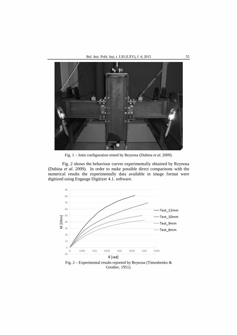
Fig. 2 shows the behaviour curves experimentally obtained by Reynosa (Dubina et al. 2009). In order to make possible direct comparisons with the numerical results the experimentally data available in image format were digitized using Engauge Digitizer 4.1. software.
Fig. 2 – Experimental results reported by Reynosa (Timoshenko &
Goodier, 1951).
56 Marcel Ghindea, Alexandru Cătărig and Robert-Istvan Ballok
3. Numerical Modelling
Softwares based on finite element method for advanced analysis are an effective tool in research. The models presented in this paper are developed using Abaqus software (Cabrero & Bayo, 2005; Reynosa, 2015). The procedure used for solving the models is Abaqus/Explicit. This package uses an explicit dynamic formulation using finite element, being devoted for dynamic simulations on short term or quasi-static simulation analysis. The reference experiment beam-column joint was performed in static-monotonous conditions. The simulation solver using Abaqus/Explicit is configured such that will result a minimum dynamic effects. The obvious goal is decreasing the simulated process to get the models that run quickly. To control the dynamic effects, post-processing for Abaqus, it allows comparison of kinetic energy curves and the internal energy resulting from deformation elements that constitute the present model. Duration analysis model achieved is 7.5 s.
All parts of the model assembly, beams, column, bolts and nuts, were defined using ”solid - homogeneous” type of elements. The used material is steel S275. The behaviour curve is theoretical being defined as a bilinear behaviour: fy = 275 N/mm2, fu = 435 N/mm2. The modulus of elasticity is 210,000 N/mm2 and the density is 7,850 kg/m3. The material used for 10.9 group bolts has the yielding limit fy = 900 N/mm2 and the breaking limit fu = 1,000 N/mm2.
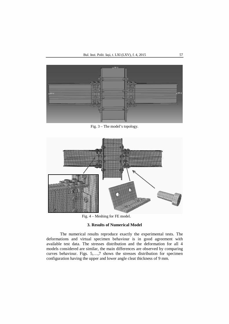
The load is applied in deflection control: the displacement is applied on the reference point RP-3 with the amplitude type ”Smooth Step”. The reactions are obtained in the reference points RP-1 and RP-2. These reference points are coupled to the beams ends and column, distributing the loads and summing the stresses obtained in the areas where are coupled. Also the outline conditions are applied to these points, suppressing degrees of freedom as in the case of laboratory stand. The topology of the model is shown in Fig. 3.
The interaction between pieces is defined by means of „General Contact”, available in Abaqus/Explicit. This act is defined with minimal effort and applies to all components. The properties of this interaction are”Hard Contact” on normal direction with friction coefficient of μ = 0.3 in tangential direction.
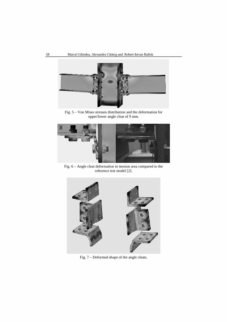
For meshing, C3D8R type hexagonal solid elements with 8 nodes and reduced integration were used. A mesh convergence study was performed to obtain an appropriate mesh density to achieve reliable results in reasonable computation time. The maximum mesh distance is 12mm for the laminated profiles and 4mm for bolts and holes. The angle cleats have a mesh of 8mm, as these elements are the most deformable one during the virtual test. The resulted meshing is presented in Fig. 4.
Bul. Inst. Polit. Iaşi, t. LXI (LXV), f. 4, 2015 57
Fig. 3 – The model’s topology.
Fig. 4 – Meshing for FE model.
3. Results of Numerical Model
The numerical results reproduce exactly the experimental tests. The deformations and virtual specimen behaviour is in good agreement with available test data. The stresses distribution and the deformation for all 4 models considered are similar, the main differences are observed by comparing curves behaviour. Figs. 5,…,7 shows the stresses distribution for specimen configuration having the upper and lower angle cleat thickness of 9 mm.
58 Marcel Ghindea, Alexandru Cătărig and Robert-Istvan Ballok
Fig. 5 – Von Mises stresses distribution and the deformation for
upper/lower angle cleat of 9 mm.
Fig. 6 – Angle cleat deformation in tension area compared to the
reference test model [2].
Fig. 7 – Deformed shape of the angle cleats.
Bul. Inst. Polit. Iaşi, t. LXI (LXV), f. 4, 2015 59
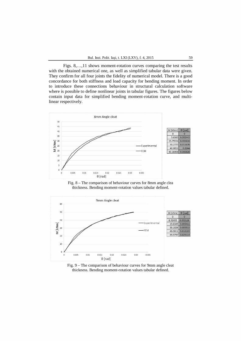
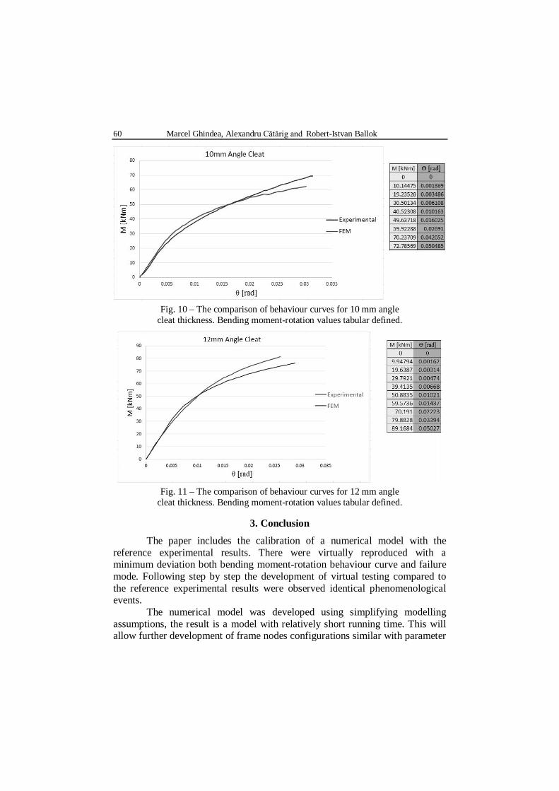
Figs. 8,…,11 shows moment-rotation curves comparing the test results with the obtained numerical one, as well as simplified tabular data were given. They confirm for all four joints the fidelity of numerical model. There is a good concordance for both stiffness and load capacity for bending moment. In order to introduce these connections behaviour in structural calculation software where is possible to define nonlinear joints in tabular figures. The figures below contain input data for simplified bending moment-rotation curve, and multi-linear respectively.
Fig. 8 – The comparison of behaviour curves for 8mm angle clea
thickness. Bending moment-rotation values tabular defined.
Fig. 9 – The comparison of behaviour curves for 9mm angle cleat thickness. Bending moment-rotation values tabular defined.
60 Marcel Ghindea, Alexandru Cătărig and Robert-Istvan Ballok
Fig. 10 – The comparison of behaviour curves for 10 mm angle cleat thickness. Bending moment-rotation values tabular defined.
Fig. 11 – The comparison of behaviour curves for 12 mm angle cleat thickness. Bending moment-rotation values tabular defined.
3. Conclusion
The paper includes the calibration of a numerical model with the reference experimental results. There were virtually reproduced with a minimum deviation both bending moment-rotation behaviour curve and failure mode. Following step by step the development of virtual testing compared to the reference experimental results were observed identical phenomenological events.
The numerical model was developed using simplifying modelling assumptions, the result is a model with relatively short running time. This will allow further development of frame nodes configurations similar with parameter
Bul. Inst. Polit. Iaşi, t. LXI (LXV), f. 4, 2015 61
variations which do not involve changes to the modelling solution and solving procedures.
Calibrated numerical model provides a better understanding of the phenomena, encountered after the joints tests having such configurations. Compared with experimental data, the numerical data are significantly numerous: depending on the mesh density they provide details for each joint of the specimen at every load step.
REFERENCES Akbar Pirmoz, Amir Seyed Khoei, Ebrahim Mohammadrezapour, Amir Saedi Daryan,
Moment–Rotation Behavior of Bolted Top–Seat Angle Connections. s.l. J. of Constructional Steel Research, 65, 973-984 (2009).
Cabrero J.M., Bayo E., Development of Practical Design Methods for Steel Structures with Semi-Rigid Connections. s.l. : Department of Structural Analysis and Design, Universidad de Navarra, Iruña, Navarre, Spain, 2005.
Dubina D, Grecea D., Ciutina A. et al., Calculul şi proiectarea îmbinărilor structurale din oţel în conformitate cu SR-EN 1993-1-8. Recomandări, comentarii şi exemple de aplicare, 2009.
Kurino H., Kobori T., Semi-Active Structural Response Control by Optimizing the Force-Deformation Loop of Variable Damper. Proc. of the 2nd World Conf. On Struct. Control. Kyoto, Japan, 1, 1999, 407-416.
Loureiro A., Reinosa J.M., Gutiérrez R., Moreno A., New Proposals on the Calculation of the Fexural Resistance in Angle Connections. s.l. J. of Constructional Steel Research, 67(4): 613-622, 2011. doi: http://dx.doi.org/10.1016/j. jcsr. 2010.11.018
Onimus A.N., Title of the Thesis. Ph.D. Diss., „Gheorghe Asachi” Techn. Univ., Jassy, 2009.
Onimus A.N., Else S.O., Other A.N., Document Preparation for Beginners and Advanced Users. J. of Civ. Engng. and Archit., 24, 3, 15-24 (2009).
Reynosa J.M., Analytical Frame Approach for the Rotational Stiffness Prediction of Beam-to-Column Angle Connections. J. of Constructional Steel Research, 106, 67-66 (2015).
Reynosa J.M., Experimental and Numerical Study of Angle Connections Assembled with European Profiles. Informes de la Construccion, 66, diciembre 2014.
Timoshenko S.P., Goodier J.N., Theory of Elasticity. 1st Ed., McGraw-Hill, New York, 1951.
White D.W., Chen W.-F., Characteristic Semi-Rigid Connection Relationship for Frame Analysis and Design. Connections in Steel Structures III: Behaviour, Strength and Design, R. Bjorhovde, A. Colson, R. Zandonini, s.l., Elsevier Science, 1996.
* * * ABAQUS user Manual, Version 6.11. * * * Dassault Systemes Simulia Corp. s.l. : Providence, RI, USA,. Abaqus Theory
Manual. 2011.
62 Marcel Ghindea, Alexandru Cătărig and Robert-Istvan Ballok
STUDIUL COMPORTÂRII ÎMBINĂRILOR METALICE SEMIRIGIDE REALIZATE
CU CORNIERE ŞI ŞURUBURI Partea 1. Dezvoltare model numeric 3-D
(Rezumat)
Această lucrare are ca subiect procesul de elaborare şi rezultatele obţinute în
urma simulării prin metode numerice a unui set de specimene de îmbinări grindă-stâlp cu elemente corniere utilizând şuruburi. Modelarea în elemente finite este realizată cu ajutorul programului Abaqus, bazate pe rezultate experimentale recente. Lucrarea prezintă modelele numerice concepute şi rezultatele pentru patru îmbinări grindă-stâlp cu şuruburi utilizând cornier inferior, superior şi pe inimă. Obiectivul lucrării de faţă este de a dezvolta un model numeric calibrat pe baza unor rezultate obţinute în laborator de către alţi cercetători, care apoi să poate fi studiat independent de datele experimentale, respectiv de a utiliza acest model pentru efectuarea unor studii parametrice, cu scopul de a obţine rezultate şi concluzii cu grad de interes ridicat în studiul comportării îmbinărilor semirigide.


![Introduction - kau.edu.sa · (Theory of Elasticity) (Timoshenko and Goodier [1] (R. Hook) 8761 (Elasticity) (Fung) [2] (Elastic) 2 (Theory of Linear (Cauchy) [3] (Thermally Isolated)](https://img.pdfslide.net/doc/110x75/5e80aa04dfbd234fba5fd5a4/introduction-kauedusa-theory-of-elasticity-timoshenko-and-goodier-1-r.jpg)


![Contributions to the theory of elasticity by Louis ... · Contributions to the theory of elasticity by Louis Napoleon George ... [15, Sections 75 and 79], and Timoshenko and Goodier](https://img.pdfslide.net/doc/110x75/5b642ead7f8b9a687e8d014e/contributions-to-the-theory-of-elasticity-by-louis-contributions-to-the.jpg)